EP1939020A1 - Telescopic actuator - Google Patents
Telescopic actuator Download PDFInfo
- Publication number
- EP1939020A1 EP1939020A1 EP07024855A EP07024855A EP1939020A1 EP 1939020 A1 EP1939020 A1 EP 1939020A1 EP 07024855 A EP07024855 A EP 07024855A EP 07024855 A EP07024855 A EP 07024855A EP 1939020 A1 EP1939020 A1 EP 1939020A1
- Authority
- EP
- European Patent Office
- Prior art keywords
- housing
- input flange
- screw member
- telescopic actuator
- pair
- Prior art date
- Legal status (The legal status is an assumption and is not a legal conclusion. Google has not performed a legal analysis and makes no representation as to the accuracy of the status listed.)
- Granted
Links
- 125000006850 spacer group Chemical group 0.000 claims description 17
- 239000000463 material Substances 0.000 claims description 3
- 230000000149 penetrating effect Effects 0.000 claims description 3
- 230000007246 mechanism Effects 0.000 description 24
- 230000002093 peripheral effect Effects 0.000 description 18
- 230000008878 coupling Effects 0.000 description 8
- 238000010168 coupling process Methods 0.000 description 8
- 238000005859 coupling reaction Methods 0.000 description 8
- 230000009467 reduction Effects 0.000 description 8
- 239000000725 suspension Substances 0.000 description 7
- 241001247986 Calotropis procera Species 0.000 description 6
- 230000008859 change Effects 0.000 description 3
- 230000000712 assembly Effects 0.000 description 2
- 238000000429 assembly Methods 0.000 description 2
- 230000002452 interceptive effect Effects 0.000 description 2
- 238000000034 method Methods 0.000 description 2
- 230000004048 modification Effects 0.000 description 2
- 238000012986 modification Methods 0.000 description 2
- 230000008569 process Effects 0.000 description 2
- 230000000452 restraining effect Effects 0.000 description 2
- 229930182556 Polyacetal Natural products 0.000 description 1
- XAGFODPZIPBFFR-UHFFFAOYSA-N aluminium Chemical compound [Al] XAGFODPZIPBFFR-UHFFFAOYSA-N 0.000 description 1
- 229910052782 aluminium Inorganic materials 0.000 description 1
- 230000005540 biological transmission Effects 0.000 description 1
- 230000001276 controlling effect Effects 0.000 description 1
- 238000013016 damping Methods 0.000 description 1
- 239000000428 dust Substances 0.000 description 1
- 239000013013 elastic material Substances 0.000 description 1
- 229920006324 polyoxymethylene Polymers 0.000 description 1
- 230000001105 regulatory effect Effects 0.000 description 1
- 229920002379 silicone rubber Polymers 0.000 description 1
- 239000004945 silicone rubber Substances 0.000 description 1
- XLYOFNOQVPJJNP-UHFFFAOYSA-N water Substances O XLYOFNOQVPJJNP-UHFFFAOYSA-N 0.000 description 1
Images



Classifications
-
- B—PERFORMING OPERATIONS; TRANSPORTING
- B60—VEHICLES IN GENERAL
- B60G—VEHICLE SUSPENSION ARRANGEMENTS
- B60G7/00—Pivoted suspension arms; Accessories thereof
- B60G7/006—Attaching arms to sprung or unsprung part of vehicle, characterised by comprising attachment means controlled by an external actuator, e.g. a fluid or electrical motor
-
- F—MECHANICAL ENGINEERING; LIGHTING; HEATING; WEAPONS; BLASTING
- F16—ENGINEERING ELEMENTS AND UNITS; GENERAL MEASURES FOR PRODUCING AND MAINTAINING EFFECTIVE FUNCTIONING OF MACHINES OR INSTALLATIONS; THERMAL INSULATION IN GENERAL
- F16D—COUPLINGS FOR TRANSMITTING ROTATION; CLUTCHES; BRAKES
- F16D3/00—Yielding couplings, i.e. with means permitting movement between the connected parts during the drive
- F16D3/02—Yielding couplings, i.e. with means permitting movement between the connected parts during the drive adapted to specific functions
- F16D3/06—Yielding couplings, i.e. with means permitting movement between the connected parts during the drive adapted to specific functions specially adapted to allow axial displacement
-
- F—MECHANICAL ENGINEERING; LIGHTING; HEATING; WEAPONS; BLASTING
- F16—ENGINEERING ELEMENTS AND UNITS; GENERAL MEASURES FOR PRODUCING AND MAINTAINING EFFECTIVE FUNCTIONING OF MACHINES OR INSTALLATIONS; THERMAL INSULATION IN GENERAL
- F16D—COUPLINGS FOR TRANSMITTING ROTATION; CLUTCHES; BRAKES
- F16D3/00—Yielding couplings, i.e. with means permitting movement between the connected parts during the drive
- F16D3/50—Yielding couplings, i.e. with means permitting movement between the connected parts during the drive with the coupling parts connected by one or more intermediate members
- F16D3/64—Yielding couplings, i.e. with means permitting movement between the connected parts during the drive with the coupling parts connected by one or more intermediate members comprising elastic elements arranged between substantially-radial walls of both coupling parts
- F16D3/68—Yielding couplings, i.e. with means permitting movement between the connected parts during the drive with the coupling parts connected by one or more intermediate members comprising elastic elements arranged between substantially-radial walls of both coupling parts the elements being made of rubber or similar material
-
- F—MECHANICAL ENGINEERING; LIGHTING; HEATING; WEAPONS; BLASTING
- F16—ENGINEERING ELEMENTS AND UNITS; GENERAL MEASURES FOR PRODUCING AND MAINTAINING EFFECTIVE FUNCTIONING OF MACHINES OR INSTALLATIONS; THERMAL INSULATION IN GENERAL
- F16H—GEARING
- F16H25/00—Gearings comprising primarily only cams, cam-followers and screw-and-nut mechanisms
- F16H25/18—Gearings comprising primarily only cams, cam-followers and screw-and-nut mechanisms for conveying or interconverting oscillating or reciprocating motions
- F16H25/20—Screw mechanisms
-
- H—ELECTRICITY
- H02—GENERATION; CONVERSION OR DISTRIBUTION OF ELECTRIC POWER
- H02K—DYNAMO-ELECTRIC MACHINES
- H02K7/00—Arrangements for handling mechanical energy structurally associated with dynamo-electric machines, e.g. structural association with mechanical driving motors or auxiliary dynamo-electric machines
- H02K7/06—Means for converting reciprocating motion into rotary motion or vice versa
-
- B—PERFORMING OPERATIONS; TRANSPORTING
- B60—VEHICLES IN GENERAL
- B60G—VEHICLE SUSPENSION ARRANGEMENTS
- B60G2200/00—Indexing codes relating to suspension types
- B60G2200/40—Indexing codes relating to the wheels in the suspensions
- B60G2200/462—Toe-in/out
-
- B—PERFORMING OPERATIONS; TRANSPORTING
- B60—VEHICLES IN GENERAL
- B60G—VEHICLE SUSPENSION ARRANGEMENTS
- B60G2202/00—Indexing codes relating to the type of spring, damper or actuator
- B60G2202/40—Type of actuator
- B60G2202/42—Electric actuator
- B60G2202/422—Linear motor
-
- B—PERFORMING OPERATIONS; TRANSPORTING
- B60—VEHICLES IN GENERAL
- B60G—VEHICLE SUSPENSION ARRANGEMENTS
- B60G2204/00—Indexing codes related to suspensions per se or to auxiliary parts
- B60G2204/40—Auxiliary suspension parts; Adjustment of suspensions
- B60G2204/419—Gears
-
- F—MECHANICAL ENGINEERING; LIGHTING; HEATING; WEAPONS; BLASTING
- F16—ENGINEERING ELEMENTS AND UNITS; GENERAL MEASURES FOR PRODUCING AND MAINTAINING EFFECTIVE FUNCTIONING OF MACHINES OR INSTALLATIONS; THERMAL INSULATION IN GENERAL
- F16H—GEARING
- F16H25/00—Gearings comprising primarily only cams, cam-followers and screw-and-nut mechanisms
- F16H25/18—Gearings comprising primarily only cams, cam-followers and screw-and-nut mechanisms for conveying or interconverting oscillating or reciprocating motions
- F16H25/20—Screw mechanisms
- F16H2025/2062—Arrangements for driving the actuator
- F16H2025/2075—Coaxial drive motors
-
- F—MECHANICAL ENGINEERING; LIGHTING; HEATING; WEAPONS; BLASTING
- F16—ENGINEERING ELEMENTS AND UNITS; GENERAL MEASURES FOR PRODUCING AND MAINTAINING EFFECTIVE FUNCTIONING OF MACHINES OR INSTALLATIONS; THERMAL INSULATION IN GENERAL
- F16H—GEARING
- F16H25/00—Gearings comprising primarily only cams, cam-followers and screw-and-nut mechanisms
- F16H25/18—Gearings comprising primarily only cams, cam-followers and screw-and-nut mechanisms for conveying or interconverting oscillating or reciprocating motions
- F16H25/20—Screw mechanisms
- F16H25/24—Elements essential to such mechanisms, e.g. screws, nuts
- F16H2025/2445—Supports or other means for compensating misalignment or offset between screw and nut
-
- F—MECHANICAL ENGINEERING; LIGHTING; HEATING; WEAPONS; BLASTING
- F16—ENGINEERING ELEMENTS AND UNITS; GENERAL MEASURES FOR PRODUCING AND MAINTAINING EFFECTIVE FUNCTIONING OF MACHINES OR INSTALLATIONS; THERMAL INSULATION IN GENERAL
- F16H—GEARING
- F16H25/00—Gearings comprising primarily only cams, cam-followers and screw-and-nut mechanisms
- F16H25/18—Gearings comprising primarily only cams, cam-followers and screw-and-nut mechanisms for conveying or interconverting oscillating or reciprocating motions
- F16H25/20—Screw mechanisms
- F16H25/22—Screw mechanisms with balls, rollers, or similar members between the co-operating parts; Elements essential to the use of such members
- F16H25/2204—Screw mechanisms with balls, rollers, or similar members between the co-operating parts; Elements essential to the use of such members with balls
-
- Y—GENERAL TAGGING OF NEW TECHNOLOGICAL DEVELOPMENTS; GENERAL TAGGING OF CROSS-SECTIONAL TECHNOLOGIES SPANNING OVER SEVERAL SECTIONS OF THE IPC; TECHNICAL SUBJECTS COVERED BY FORMER USPC CROSS-REFERENCE ART COLLECTIONS [XRACs] AND DIGESTS
- Y10—TECHNICAL SUBJECTS COVERED BY FORMER USPC
- Y10T—TECHNICAL SUBJECTS COVERED BY FORMER US CLASSIFICATION
- Y10T74/00—Machine element or mechanism
- Y10T74/18—Mechanical movements
- Y10T74/18568—Reciprocating or oscillating to or from alternating rotary
- Y10T74/18576—Reciprocating or oscillating to or from alternating rotary including screw and nut
-
- Y—GENERAL TAGGING OF NEW TECHNOLOGICAL DEVELOPMENTS; GENERAL TAGGING OF CROSS-SECTIONAL TECHNOLOGIES SPANNING OVER SEVERAL SECTIONS OF THE IPC; TECHNICAL SUBJECTS COVERED BY FORMER USPC CROSS-REFERENCE ART COLLECTIONS [XRACs] AND DIGESTS
- Y10—TECHNICAL SUBJECTS COVERED BY FORMER USPC
- Y10T—TECHNICAL SUBJECTS COVERED BY FORMER US CLASSIFICATION
- Y10T74/00—Machine element or mechanism
- Y10T74/18—Mechanical movements
- Y10T74/18568—Reciprocating or oscillating to or from alternating rotary
- Y10T74/18576—Reciprocating or oscillating to or from alternating rotary including screw and nut
- Y10T74/18672—Plural screws in series [e.g., telescoping, etc.]
Definitions
- the present invention relates to a telescopic actuator having a screw feed mechanism configured such that a male screw member coupled to an input flange is threadedly engaged with a female screw member coupled to an output rod, in which the input flange is rotated by a motor to move the output rod in an axial direction for outputting a thrust force.
- an upper link and a lower link are controlled to protrude or to retract by an actuator, thereby restraining variations in camber angle and tread of a wheel caused by bumping and rebounding in order to enhance steering stability performance (see, e.g., JP 6-047388 B2 ).
- the actuator includes a motor and a feed screw mechanism in which a male screw member is relatively rotated with respect to a female screw member by the motor.
- a male screw member is rotatably supported by a housing through a ball bearing, a female screw member is supported by the housing via a slide bearing so as to be slidable in an axial direction thereof, and the male screw member is threadedly engaged with the female screw member.
- movements of the male and female screw members in a radial direction are regulated so that, when an excessive load is applied between the male and female screw members in the radial direction load, a smooth actuation of the feed screw mechanism is obstructed.
- the present invention is made in view of foregoing circumstances, and provides a telescopic actuator having a feed screw mechanism in which a radial load is prevented from being excessively applied between a male screw member and a female screw member to enable a smooth actuation of the feed screw mechanism.
- a telescopic actuator includes a motor, an input flange rotated by the motor, a male screw member coupled to the input flange, a female screw member threadedly engaged with the male screw member, an output rod coupled to the female screw member, the output rod being moved in an axial direction thereof to output a thrust force when the input flange is rotated, and a housing inside which the male screw member and the female screw member are accommodated.
- the input flange is supported by the housing such that a relative movement of the input flange with respect to the housing is allowed in a radial direction but restricted in the axial direction.
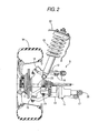
- a double wishbone type rear suspension S for use in a four wheel steering system vehicle includes a knuckle 11 rotatably supporting a rear wheel W (a wheel), an upper arm 12 and a lower arm 13 respectively coupling the knuckle 11 to a vehicle body such that the knuckle 11 is movable in a vertical direction, a toe control actuator 14 (a telescopic actuator) coupling the knuckle 11 and the vehicle body to control a toe angle of the rear wheel W, a damper 15 with a suspension spring for damping the vertical movement of the rear wheel W.
- Each of the upper arm 12 and the lower arms 13 has a base end coupled to the vehicle body via a rubber bush joint 16, 17 and a leading end coupled to an upper portion or a lower portion of the knuckle 11 via ball joints 18, 19.
- the toe control actuator 14 has a base end coupled to the vehicle body via a rubber bush joint 20 and a leading end coupled to a rear portion of the knuckle 11 via another rubber bush joint 21.
- the damper 15 has an upper end fixed to the vehicle body, e.g., to an upper wall 22 of a suspension tower, and a lower end coupled to the upper portion of the knuckle 11 via a rubber bush joint 23.
- the toe control actuator 14 When the toe control actuator 14 is extended, the rear portion of the knuckle 11 is pushed outwardly in a vehicle width direction, whereby the toe angle of the rear wheel W is changed toward a toe-in direction. When the toe control actuator 14 is contracted, the rear portion of the knuckle 11 is pulled inwardly in the vehicle width direction, whereby the toe angle of the rear wheel W is changed toward a toe-out direction. Accordingly, besides a normal front wheel steering by operating a steering wheel, the toe angle of the rear wheel W is controlled in accordance with a vehicle speed and a steering angle of the steering wheel. Thus, straight running stability performance and turning performance of a vehicle can be enhanced.
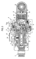
- the toe control actuator 14 includes a first housing 31 to which the rubber bush joint 20 to be coupled to the vehicle body is integrally provided, and a second housing 32 (a housing) to which the rubber bush joint 21 to be coupled to the knuckle 11 is provided.
- the second housing 32 supports an output rod 33 such that the output rod 33 is protrudable and retractible with respect to the second housing 32.
- the mutually opposing portions of the first and second housings 31, 32 are socket fitted with each other with a seal member 34 interposed therebetween.
- the respective opposing portions have joining flanges 31a, 32a that are fastened together with bolts 35.
- a brush-equipped motor 36 which functions as a drive source, is accommodated inside the first housing 31.
- a planetary gear type reduction gear 37, an elastic coupling 38, and a feed screw mechanism 39 having a trapezoidal screw thread are accommodated inside the second housing 32.
- the first housing 31 accommodating the motor 36 and the second housing 32 accommodating the reduction gear 37, the coupling 38 and the feed screw mechanism 39 are respectively assembled beforehand as sub assemblies, and the respective sub assemblies are then joined together as the toe control actuator 14.
- the first housing 31 and the second housing 32 are joined in a detachable manner. Therefore, the motor 36 may be replaced with a motor having a greater output or a smaller output, or operation characteristic of the reduction gear 37 and/or the feed screw mechanism 39 may be changed simply by replacing the sub assembly of the first housing 31 or the second housing 31 without changing the entire design of the toe control actuator 14. This can enhance versatility with respect to various models and designs, and thus can reduce cost.
- a yoke 40 having a shape of a cup and a bearing holder 42 constitutes an outer shape of the motor 36.
- the yoke 40 has a flange 40a to which the bearing holder 42 is fastened with bolts 41.
- the bolts 41 are screwed into the first housing 31 on a surface facing the second housing 32, whereby the motor 36 is fixed to the first housing 31.
- An annular stator 43 is supported on an inner peripheral surface of the yoke 40.
- a rotor 44 is disposed on an inner side the stator 43.
- a rotation shaft of the rotor has one end rotatably supported on a ball bearing 46 which is provided at a bottom portion of the cup-shaped yoke 40, and the other end rotatably supported on another ball bearing 47 provided on the bearing holder 42.
- a brush 49 is supported on an inner surface of the bearing holder 42. The brush slidingly contacts with a commutator 48 provided on an outer periphery of the rotation shaft 45.
- a conducting wire 50 extending from the brush 49 is drawn out through a grommet 51 provided on the first housing 31.
- the yoke 40 which forms a part of the outer shape of the motor 36, is a rigid member for accommodating the stator 43 and rotor 44 therein. Because this yoke 40 is fixed to the first housing 31, a load input from the rear wheel W to the toe control actuator 14 is received by the first housing 31 so that the load is less likely to be applied to the motor 36. Thus, durability and reliability of the motor 36 can be enhanced. Further, a clearance ⁇ (a space) is provided between an outer peripheral surface of the yoke 40 of the motor 36 and an inner peripheral surface of the first housing 31. This clearance ⁇ restrains an actuation noise of the motor 36 from leaking out from the first housing 31. Moreover, the clearance ⁇ additionally helps to restrain an external force acting on the first housing 31 from being transmitted to the motor 36.
- the motor 36 and the first housing 31 are fixed together with the bolts 41 that are used to fasten the yoke 40 of the motor 36 and the bearing holder 42. Therefore, compared with a case in which the motor 36 is fixed to the first housing 31 with bolts other than the bolts 41, the number of bolts can be reduced. Also, a space required for arranging the extra bolts can be saved. Accordingly, it is possible to provide the toe control actuator 14 of a smaller size.
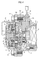
- the reduction gear 37 includes a first planetary gear mechanism 61 and a second planetary gear mechanism 62 that are coupled in to have a two-stage structure, i.e., a tandem arrangement.
- the first planetary gear mechanism 61 includes a ring gear 63 fixedly fitted into an opening portion of the second housing 32, a first sun gear 64 formed directly on a leading end of the rotation shaft 45 of the motor 36, a first disk-shaped carrier 65, and four first pinions 68.
- Each of the first pinions 68 is rotatably supported on an associated one of first pinion pins 66 via respective ball bearings 67, and is engaged with both the ring gear 63 and the first sun gear 64.
- the first pinion pins 66 are press-fitted into the first carrier 65, and are supported by the first carrier 65 in a cantilevered manner.
- a rotation of the first sun gear 64 (a first input member) is decelerated and transmitted to the first carrier 65 (a first output member).
- the second planetary gear mechanism 62 includes the ring gear 63, which is shared with the first planetary gear mechanism 61, a second sun gear 69 fixed to the center of the first carrier 65, a disk-shaped second carrier 70, and four second pinions 73.
- Each of the second pinions 73 is rotatably supported on an associated one of second pinion pins 71 via respective slide bushes 72, and is engaged with both the ring gear 63 and the second sun gear 69.
- the second pinion pins 71 are press fitted into the second carrier 70, and are supported by the second carrier 70 in a cantilevered manner.
- a rotation of the second sun gear 69 (a second input member) is decelerated and transmitted to the second carrier 70 (a second output member).
- the first and second planetary gear mechanisms 61, 62 are coupled together in series. Therefore, a large deceleration ratio (a gear reduction ratio) can be obtained with a smaller size of the reduction gear 37.
- the sun gear 64 of the first planetary gear mechanism 61 is not fixed to the rotation shaft 45 of the motor 36 but is formed directly on the rotation shaft 45.
- the number of parts can be reduced.
- a diameter of the first sun gear 64 can be minimized so that a large deceleration ratio can be set in the first planetary gear mechanism 61.
- the second carrier 70 which is an output member of the reduction gear 37, is coupled to an input flange 74, which is an input member of the feed screw mechanism 39, via the coupling 38.
- the input flange 74 is formed substantially in a disk shape, and is rotatably supported by a pair of thrust bearings 75, 76 holding an outer peripheral portion of the input flange 74 therebetween. More specifically, a ring-shaped lock nut 78 is fastened into an inner peripheral surface of the second housing 32 such that a spacer collar 77 is sandwiched therebetween. Thus, a relative movement of the lock nut 78 with respect to the second housing 32 in the axial direction is restricted.
- the thrust bearing 75 is arranged so as to support a thrust load between the second housing 32 and input flange 74 while the other thrust bearing 76 is arranged so as to support a thrust load between the lock nut 78 and input flange 74.
- the coupling 38 includes two outer elastic bushes 79 (an elastic bush portion) made of, e.g., polyacetal, and an inner elastic bush 80 (an elastic bush portion) made of, e.g., silicone rubber.
- Each of the outer elastic bushes 79 has eight projections 79a extending radially from an outer circumference thereof.
- the projections 79a are disposed at regular intervals along a circumferential direction of each of the outer elastic bushes 79 with eight grooves 79b being formed between each of the adjacent projections 79a.
- the inner elastic bush 80 has eight projections 80a extending radially from an outer circumference thereof.
- the projections 80a are disposed at regular intervals along a circumferential direction of the inner elastic bush 80 with eight grooves 80b being formed between each of the adjacent projections 80a.
- the second carrier 70 has four pawls 70a formed on a surface facing the input flange 74.
- the pawls 70a are disposed at regular intervals, each extending in an axial direction.
- the input flange 74 has four pawls 74a form on a surface facing the second carrier 70.
- the pawls 74a are disposed at regular intervals, each extending in the axial direction.
- the inner elastic bush 80 is sandwiched between the outer elastic bushes 79 such that the projections 79a, 80a are in phase with each other, i.e., axially aligned.
- the pawls 70a of the second carrier 70 and the pawls 74a of the input flange 74 are alternately engaged with eight groove sections, each of the sections being formed by the grooves 79b, 80b that are axially aligned.
- a torque of the second carrier 70 is transmitted from the pawls 70a of the second carrier 70 to the input flange 74 through the projections 79a, 80a of the outer and inner elastic bushes 79, 80 and the pawls 74a of the input flange 74.
- the outer elastic bushes 79 and the inner elastic bush 80 are both made of elastic material.
- the outer elastic bushes 79 and the inner elastic bush 80 absorb a slight axial difference between the second carrier 70 and the input flange 74, and also absorb a sudden change of the torque, thereby enabling a smooth power transmission.
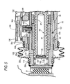
- a first slide bearing 91 is fixed to the inner peripheral surface of the second housing 32 at an intermediate portion of the second housing 32 in the axial direction.
- a second slide bearing 92 is fixed to an inner peripheral surface of an end member 93 screwed into an end portion of the second housing 32 in the axial direction.
- the output rod 33 is slidably supported by the first and second slide bearings 91, 92.
- the feed screw mechanism 39 converts the rotation of the input flange 74 to a thrust movement of the output rod 33.
- the feed screw mechanism 39 includes a male screw member 95 penetrating through the center of the input flange 74 and fastened with a nut 94 (see Fig.
- the male screw member 95 is a hollow member formed with a hole penetrating in an axial direction, i.e., in a longitudinal direction thereof.
- the output rod 33 is supported inside the second housing 32 a plurality of slide bearings 91, 92 (two in the embodiment). Therefore, a radial load applied to the output rod 33 can be reliably supported by the second housing 32, thereby preventing the radial load from being applied from the female screw member 96 to the male screw member 95.
- a spring base 99 is supported via a thrust bearing 98 at a leading end of the male screw member 95.
- a coil spring 101 is compressed between the spring base 99 and another spring base 100 provided on a leading end of the output rod 33.
- the spring force of the coil spring 101 biases the female spring member 96 fixed to the output rod 33 and the male screw member 95 in threaded engagement with the female screw member 96 in opposite directions respectively, thereby eliminating play between threads of the male and female screw members 95,96.
- the threads of the male and female screw members 95, 96 are always in close contact with each other so that frictional force is generated. Therefore, in a case where a vibratory load is input to the female screw member 96 from the rear wheel W, or where a large load is input to the female screw member 96 from the rear wheel W, it is possible to prevent the male screw member 95 from rotating spontaneously and thus to prevent the toe angle of the rear wheel W from changing unexpectedly. Thus, control accuracy of the toe angle is improved. As a result, there is no need to apply a current to the motor 36 for the purpose of restraining an unintentional rotation of the male screw member 95, reducing power consumption of the motor 36.
- a stroke sensor 102 is provided in the second housing 32.
- the stroke sensor 102 detects an axial position of the output rod 33 and feeds back the detected axial position to a control unit.
- the stroke sensor 102 includes a detectable portion 104 fixed to the outer peripheral surface of the output rod 33 with a bolt 103, and a sensor main body 106 accommodating a detecting portion 105 which detects a position of the detectable portion 104.
- the detectable portion 104 may be a permanent magnet, and the detecting portion 105 may be a coil which magnetically detects the position of the detectable portion 104.
- the second housing 32 includes an opening portion 32b which provides a clearance having a certain length in the axial direction. The opening portion 32b allows the output rod 33 and the detectable portion 104 to move without interfering with the second housing 32.
- a ring-shaped stopper 107 is provided on the outer peripheral surface of the output rod 33.
- the stopper 107 When the output rod 33 is moved in a protruding direction, the stopper 107 eventually hits a contact surface 93b of the end member 93, whereby the output rod 33 reaches its outermost position.
- the stopper 107 reliably prevents the output rod 33 from slipping out of the second housing 32. Because the stopper 107 is disposed within a dead space between the first and second slide bearings 91, 92, a space can be saved.
- the end member 93, on which the second slide bearing 92 is provided, can be separated from the second housing 32. Therefore, the output rod 33 equipped with the stopper 107 can be attached to and detached from the second housing 32 without interfering with the second slide bearing 92.
- a boot 108 is provided in order to prevent water and dust from entering a gap between the second housing 32 and output rod 33.
- the boot 108 has one end portion fitted in a circumferential stepped portion 32c of the second housing 32 and the other end portion fitted in a circumferential groove 33a of the output rod 33.
- the respective end portions of the boot 108 are then fixed by associated bands 109, 110.
- a flange 93a of the end member 93 forms a circumferential groove together with the circumferential stepped portion 32c of the second housing 32.
- the flange 93a of the end member 93 is utilized to prevent the boot 108 from slipping off, it is not necessary to form a circumferential groove on the second housing 32. Compared with a process of forming a circumferential groove on the second housing 32, a process of forming the circumferential stepped portion 32c is easier. Further, because the circumferential stepped portion 32c requires only one shoulder portion while a circumferential groove requires two shoulder portions, a dimension of the second housing 32 in the axial direction can be reduced by an amount equivalent to a width of one of the two shoulder portions.
- a hole 33b is formed through the output rod 33 so as to communicate an internal space of the hollow output rod 33 and an internal space of the boot 108. This hole 33b allows the boot 108 to absorb the change of the above-mentioned inner pressure by deforming, thereby enabling the smooth actuation of the toe control actuator 14.
- the pair of thrust bearings 75, 76 holds the respective side surfaces of the input flange 74 therebetween and supports the thrust load. Further, as shown in Fig. 8 , a slight clearance ⁇ is provided between the outer peripheral surface of the input flange 74 and an inner peripheral surface of the spacer collar 77 so as to allow the input flange 74 to move in the radial direction.
- the male screw member 95 coupled to the input flange 4 is floatingly supported such that the male screw member 95 is relatively movable in the radial direction with respect to the female screw member 96. Therefore, a radial load is prevented from being excessively applied to respective engaging portions of the male screw member 95 and the female screw member 96, thereby enabling a smooth actuation of the feed screw mechanism 39.
- Both the second housing 32 and the spacer collar 77, which is fixed to the second housing 32 by the lock nut 78, may be made of same material, e.g., aluminum material. In such a case, a fastening axial force of the lock nut 78 can be prevented from varying due to thermal expansion caused by temperature change, thereby enabling a stable support of the input flange 74 with the thrust bearings 75, 76.
- the thrust bearing 75 contacts the washer 115 on a side of the second housing 32 and also contacts another washer 115' on a side of the input flange 74, whereas the other thrust bearing 76 contacts the washer 116 on a side of the lock nut 78 and also contacts another washer 116' on a side of the input flange 74.
- Respective ends of the spacer collar 77 directly contact the second housing 32 and the lock nut 78 respectively, whereby the spacer collar 77 is held therebetween. Accordingly, outer peripheral portions of the respective washers 115, 115', 116, 116' face the inner peripheral portion of the spacer collar 77.
- a thickness of the input flange 74 is expressed as A
- a thickness of each of the four washers 115, 115', 116, 116' is expressed as B
- a thickness of each of the thrust bearings 75, 76 is expressed as C
- their tolerances are respectively expressed as ⁇ A, ⁇ B, ⁇ C
- the tolerance ⁇ D exists in the thickness D of the spacer collar 77
- the maximum value of the play reaches ⁇ A + 4 x ⁇ B + 2 x ⁇ C + ⁇ D.
- the play to be generated in relation to the thrust bearings 75, 76 can be reduced.
- the number of the washers 115, 116 required in the embodiment shown in Fig. 8 is two, which is less by two than the configuration shown in Fig. 9 in which the number of the washers 115, 115', 116, 116 is four.
- the number of parts required in the structure can be reduced while also reducing the axial dimension of the structure.
- the lock nut 78 which is used to fix the two washers 115, 116 and the spacer collar 77 to the second housing 32, is formed to have an L-shaped section, thereby providing a recessed portion 78a on a rear surface thereof. According to this structure, the outer peripheral portion of the second carrier 70 can be disposed inside the recessed portion 78a so that the second planetary gear mechanism 62 is disposed closer to the coupling 38, thereby reducing the axial dimension of the structure.
- a telescopic actuator according to the present invention is used as the toe control actuator 14 in the above-described embodiment, it may be used for other various purposes.
- a load to be downwardly applied to the spring of the suspension S can be reduced due to its small size and light weight.
- a telescopic actuator includes a motor, an input flange rotated by the motor, a male screw member coupled to the input flange, a female screw member threadedly engaged with the male screw member, an output rod coupled to the female screw member, the output rod being moved in an axial direction thereof to output a thrust force when the input flange is rotated, and a housing inside which the male screw member and the female screw member are accommodated.
- the input flange is supported by the housing such that a relative movement of the input flange with respect to the housing is allowed in a radial direction but restricted in the axial direction.
Landscapes
- Engineering & Computer Science (AREA)
- General Engineering & Computer Science (AREA)
- Mechanical Engineering (AREA)
- Power Engineering (AREA)
- Power Steering Mechanism (AREA)
- Connection Of Motors, Electrical Generators, Mechanical Devices, And The Like (AREA)
- Steering-Linkage Mechanisms And Four-Wheel Steering (AREA)
- Vehicle Body Suspensions (AREA)
- Transmission Devices (AREA)
Abstract
Description
- The present invention relates to a telescopic actuator having a screw feed mechanism configured such that a male screw member coupled to an input flange is threadedly engaged with a female screw member coupled to an output rod, in which the input flange is rotated by a motor to move the output rod in an axial direction for outputting a thrust force.
- In a suspension apparatus of a vehicle, for example, an upper link and a lower link are controlled to protrude or to retract by an actuator, thereby restraining variations in camber angle and tread of a wheel caused by bumping and rebounding in order to enhance steering stability performance (see, e.g.,
JP 6-047388 B2 - In this type of actuator having a feed screw mechanism, a male screw member is rotatably supported by a housing through a ball bearing, a female screw member is supported by the housing via a slide bearing so as to be slidable in an axial direction thereof, and the male screw member is threadedly engaged with the female screw member. However, according to this configuration, movements of the male and female screw members in a radial direction are regulated so that, when an excessive load is applied between the male and female screw members in the radial direction load, a smooth actuation of the feed screw mechanism is obstructed.
- The present invention is made in view of foregoing circumstances, and provides a telescopic actuator having a feed screw mechanism in which a radial load is prevented from being excessively applied between a male screw member and a female screw member to enable a smooth actuation of the feed screw mechanism.
- According to an aspect of the invention, a telescopic actuator includes a motor, an input flange rotated by the motor, a male screw member coupled to the input flange, a female screw member threadedly engaged with the male screw member, an output rod coupled to the female screw member, the output rod being moved in an axial direction thereof to output a thrust force when the input flange is rotated, and a housing inside which the male screw member and the female screw member are accommodated. The input flange is supported by the housing such that a relative movement of the input flange with respect to the housing is allowed in a radial direction but restricted in the axial direction.
- Other aspects and advantages of the invention will be apparent from the following description, the drawings and the claims.
-
-
Fig. 1 is a perspective view of a suspension apparatus for a left rear wheel. -
Fig. 2 is a view of the suspension apparatus when seen in adirection 2 shown inFig. 1 . -
Fig. 3 is a longitudinal section view of a toe control actuator. -
Fig. 4 is an enlarged view of the portion 4 shown inFig. 3 . -
Fig. 5 is an enlarged view of theportion 5 shown inFig. 3 . -
Fig. 6 is an exploded perspective view of a reduction gear and a coupling. -
Fig. 7 is an enlarged section view taken along the line 7-7 shown inFig. 3 . -
Fig. 8 is an enlarged view of theportion 8 shown inFig. 4 . -
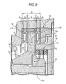
Fig. 9 is a view corresponding toFig. 8 but illustrating a configuration of a related art - Hereinafter, embodiments of the invention will be explained with reference to the drawings. The following exemplary embodiments do not limit the scope of the invention.
- As shown in
Figs. 1 and2 , a double wishbone type rear suspension S for use in a four wheel steering system vehicle includes aknuckle 11 rotatably supporting a rear wheel W (a wheel), anupper arm 12 and alower arm 13 respectively coupling theknuckle 11 to a vehicle body such that theknuckle 11 is movable in a vertical direction, a toe control actuator 14 (a telescopic actuator) coupling theknuckle 11 and the vehicle body to control a toe angle of the rear wheel W, adamper 15 with a suspension spring for damping the vertical movement of the rear wheel W. - Each of the
upper arm 12 and thelower arms 13 has a base end coupled to the vehicle body via arubber bush joint knuckle 11 viaball joints toe control actuator 14 has a base end coupled to the vehicle body via arubber bush joint 20 and a leading end coupled to a rear portion of theknuckle 11 via anotherrubber bush joint 21. Thedamper 15 has an upper end fixed to the vehicle body, e.g., to anupper wall 22 of a suspension tower, and a lower end coupled to the upper portion of theknuckle 11 via arubber bush joint 23. - When the
toe control actuator 14 is extended, the rear portion of theknuckle 11 is pushed outwardly in a vehicle width direction, whereby the toe angle of the rear wheel W is changed toward a toe-in direction. When thetoe control actuator 14 is contracted, the rear portion of theknuckle 11 is pulled inwardly in the vehicle width direction, whereby the toe angle of the rear wheel W is changed toward a toe-out direction. Accordingly, besides a normal front wheel steering by operating a steering wheel, the toe angle of the rear wheel W is controlled in accordance with a vehicle speed and a steering angle of the steering wheel. Thus, straight running stability performance and turning performance of a vehicle can be enhanced. - Next, a structure of the
toe control actuator 14 will be described below in detail with reference toFigs. 3 to 7 . - As shown in
Figs. 3 and4 , thetoe control actuator 14 includes afirst housing 31 to which therubber bush joint 20 to be coupled to the vehicle body is integrally provided, and a second housing 32 (a housing) to which therubber bush joint 21 to be coupled to theknuckle 11 is provided. Thesecond housing 32 supports anoutput rod 33 such that theoutput rod 33 is protrudable and retractible with respect to thesecond housing 32. The mutually opposing portions of the first andsecond housings seal member 34 interposed therebetween. The respective opposing portions have joiningflanges bolts 35. A brush-equippedmotor 36, which functions as a drive source, is accommodated inside thefirst housing 31. A planetary geartype reduction gear 37, anelastic coupling 38, and afeed screw mechanism 39 having a trapezoidal screw thread are accommodated inside thesecond housing 32. - The
first housing 31 accommodating themotor 36 and thesecond housing 32 accommodating thereduction gear 37, thecoupling 38 and thefeed screw mechanism 39 are respectively assembled beforehand as sub assemblies, and the respective sub assemblies are then joined together as thetoe control actuator 14. Thefirst housing 31 and thesecond housing 32 are joined in a detachable manner. Therefore, themotor 36 may be replaced with a motor having a greater output or a smaller output, or operation characteristic of thereduction gear 37 and/or thefeed screw mechanism 39 may be changed simply by replacing the sub assembly of thefirst housing 31 or thesecond housing 31 without changing the entire design of thetoe control actuator 14. This can enhance versatility with respect to various models and designs, and thus can reduce cost. - A
yoke 40 having a shape of a cup and abearing holder 42 constitutes an outer shape of themotor 36. Theyoke 40 has aflange 40a to which thebearing holder 42 is fastened withbolts 41. Thebolts 41 are screwed into thefirst housing 31 on a surface facing thesecond housing 32, whereby themotor 36 is fixed to thefirst housing 31. - An
annular stator 43 is supported on an inner peripheral surface of theyoke 40. Arotor 44 is disposed on an inner side thestator 43. A rotation shaft of the rotor has one end rotatably supported on a ball bearing 46 which is provided at a bottom portion of the cup-shaped yoke 40, and the other end rotatably supported on another ball bearing 47 provided on thebearing holder 42. Abrush 49 is supported on an inner surface of thebearing holder 42. The brush slidingly contacts with acommutator 48 provided on an outer periphery of therotation shaft 45. A conductingwire 50 extending from thebrush 49 is drawn out through agrommet 51 provided on thefirst housing 31. - The
yoke 40, which forms a part of the outer shape of themotor 36, is a rigid member for accommodating thestator 43 androtor 44 therein. Because thisyoke 40 is fixed to thefirst housing 31, a load input from the rear wheel W to thetoe control actuator 14 is received by thefirst housing 31 so that the load is less likely to be applied to themotor 36. Thus, durability and reliability of themotor 36 can be enhanced. Further, a clearance α (a space) is provided between an outer peripheral surface of theyoke 40 of themotor 36 and an inner peripheral surface of thefirst housing 31. This clearance α restrains an actuation noise of themotor 36 from leaking out from thefirst housing 31. Moreover, the clearance α additionally helps to restrain an external force acting on thefirst housing 31 from being transmitted to themotor 36. - Further, the
motor 36 and thefirst housing 31 are fixed together with thebolts 41 that are used to fasten theyoke 40 of themotor 36 and thebearing holder 42. Therefore, compared with a case in which themotor 36 is fixed to thefirst housing 31 with bolts other than thebolts 41, the number of bolts can be reduced. Also, a space required for arranging the extra bolts can be saved. Accordingly, it is possible to provide thetoe control actuator 14 of a smaller size. - As shown in
Figs. 3 and4 , thereduction gear 37 includes a firstplanetary gear mechanism 61 and a secondplanetary gear mechanism 62 that are coupled in to have a two-stage structure, i.e., a tandem arrangement. The firstplanetary gear mechanism 61 includes aring gear 63 fixedly fitted into an opening portion of thesecond housing 32, afirst sun gear 64 formed directly on a leading end of therotation shaft 45 of themotor 36, a first disk-shaped carrier 65, and fourfirst pinions 68. Each of the first pinions 68 is rotatably supported on an associated one of first pinion pins 66 viarespective ball bearings 67, and is engaged with both thering gear 63 and thefirst sun gear 64. The first pinion pins 66 are press-fitted into thefirst carrier 65, and are supported by thefirst carrier 65 in a cantilevered manner. In the firstplanetary gear mechanism 61, a rotation of the first sun gear 64 (a first input member) is decelerated and transmitted to the first carrier 65 (a first output member). - The second
planetary gear mechanism 62 includes thering gear 63, which is shared with the firstplanetary gear mechanism 61, asecond sun gear 69 fixed to the center of thefirst carrier 65, a disk-shapedsecond carrier 70, and foursecond pinions 73. Each of the second pinions 73 is rotatably supported on an associated one of second pinion pins 71 viarespective slide bushes 72, and is engaged with both thering gear 63 and thesecond sun gear 69. The second pinion pins 71 are press fitted into thesecond carrier 70, and are supported by thesecond carrier 70 in a cantilevered manner. In the secondplanetary gear mechanism 62, a rotation of the second sun gear 69 (a second input member) is decelerated and transmitted to the second carrier 70 (a second output member). - As described above, the first and second
planetary gear mechanisms reduction gear 37. Also, thesun gear 64 of the firstplanetary gear mechanism 61 is not fixed to therotation shaft 45 of themotor 36 but is formed directly on therotation shaft 45. Thus, compared with a structure in which afirst sun gear 64 is provided separately from therotation shaft 45, the number of parts can be reduced. Further, a diameter of thefirst sun gear 64 can be minimized so that a large deceleration ratio can be set in the firstplanetary gear mechanism 61. - The
second carrier 70, which is an output member of thereduction gear 37, is coupled to aninput flange 74, which is an input member of thefeed screw mechanism 39, via thecoupling 38. Theinput flange 74 is formed substantially in a disk shape, and is rotatably supported by a pair ofthrust bearings input flange 74 therebetween. More specifically, a ring-shapedlock nut 78 is fastened into an inner peripheral surface of thesecond housing 32 such that aspacer collar 77 is sandwiched therebetween. Thus, a relative movement of thelock nut 78 with respect to thesecond housing 32 in the axial direction is restricted. Thethrust bearing 75 is arranged so as to support a thrust load between thesecond housing 32 andinput flange 74 while the other thrust bearing 76 is arranged so as to support a thrust load between thelock nut 78 andinput flange 74. - As shown in
Figs. 4 ,6 and7 , thecoupling 38 includes two outer elastic bushes 79 (an elastic bush portion) made of, e.g., polyacetal, and an inner elastic bush 80 (an elastic bush portion) made of, e.g., silicone rubber. Each of the outerelastic bushes 79 has eightprojections 79a extending radially from an outer circumference thereof. Theprojections 79a are disposed at regular intervals along a circumferential direction of each of the outerelastic bushes 79 with eightgrooves 79b being formed between each of theadjacent projections 79a. Likewise, the innerelastic bush 80 has eightprojections 80a extending radially from an outer circumference thereof. Theprojections 80a are disposed at regular intervals along a circumferential direction of the innerelastic bush 80 with eightgrooves 80b being formed between each of theadjacent projections 80a. Thesecond carrier 70 has fourpawls 70a formed on a surface facing theinput flange 74. Thepawls 70a are disposed at regular intervals, each extending in an axial direction. Likewise, theinput flange 74 has fourpawls 74a form on a surface facing thesecond carrier 70. Thepawls 74a are disposed at regular intervals, each extending in the axial direction. - The inner
elastic bush 80 is sandwiched between the outerelastic bushes 79 such that theprojections pawls 70a of thesecond carrier 70 and thepawls 74a of theinput flange 74 are alternately engaged with eight groove sections, each of the sections being formed by thegrooves - Accordingly, a torque of the
second carrier 70 is transmitted from thepawls 70a of thesecond carrier 70 to theinput flange 74 through theprojections elastic bushes pawls 74a of theinput flange 74. The outerelastic bushes 79 and the innerelastic bush 80 are both made of elastic material. Thus, the outerelastic bushes 79 and the innerelastic bush 80 absorb a slight axial difference between thesecond carrier 70 and theinput flange 74, and also absorb a sudden change of the torque, thereby enabling a smooth power transmission. - As shown in
Fig. 5 , a first slide bearing 91 is fixed to the inner peripheral surface of thesecond housing 32 at an intermediate portion of thesecond housing 32 in the axial direction. A second slide bearing 92 is fixed to an inner peripheral surface of anend member 93 screwed into an end portion of thesecond housing 32 in the axial direction. Theoutput rod 33 is slidably supported by the first andsecond slide bearings feed screw mechanism 39 converts the rotation of theinput flange 74 to a thrust movement of theoutput rod 33. Thefeed screw mechanism 39 includes amale screw member 95 penetrating through the center of theinput flange 74 and fastened with a nut 94 (seeFig. 4 ), and afemale screw member 96 threadedly engaged with an outer peripheral surface of themale screw member 95. Thefemale screw member 96 is fitted inside the inner peripheral surface of thehollow output rod 33, and is fixed thereto by alock nut 97. Themale screw member 95 is a hollow member formed with a hole penetrating in an axial direction, i.e., in a longitudinal direction thereof. - As described above, the
output rod 33 is supported inside thesecond housing 32 a plurality ofslide bearings 91, 92 (two in the embodiment). Therefore, a radial load applied to theoutput rod 33 can be reliably supported by thesecond housing 32, thereby preventing the radial load from being applied from thefemale screw member 96 to themale screw member 95. - A
spring base 99 is supported via athrust bearing 98 at a leading end of themale screw member 95. Acoil spring 101 is compressed between thespring base 99 and anotherspring base 100 provided on a leading end of theoutput rod 33. The spring force of thecoil spring 101 biases thefemale spring member 96 fixed to theoutput rod 33 and themale screw member 95 in threaded engagement with thefemale screw member 96 in opposite directions respectively, thereby eliminating play between threads of the male andfemale screw members - According to the above configuration, the threads of the male and
female screw members female screw member 96 from the rear wheel W, or where a large load is input to thefemale screw member 96 from the rear wheel W, it is possible to prevent themale screw member 95 from rotating spontaneously and thus to prevent the toe angle of the rear wheel W from changing unexpectedly. Thus, control accuracy of the toe angle is improved. As a result, there is no need to apply a current to themotor 36 for the purpose of restraining an unintentional rotation of themale screw member 95, reducing power consumption of themotor 36. - A
stroke sensor 102 is provided in thesecond housing 32. When controlling a telescopic movement of thetoe control actuator 14, thestroke sensor 102 detects an axial position of theoutput rod 33 and feeds back the detected axial position to a control unit. Thestroke sensor 102 includes adetectable portion 104 fixed to the outer peripheral surface of theoutput rod 33 with abolt 103, and a sensormain body 106 accommodating a detectingportion 105 which detects a position of thedetectable portion 104. Thedetectable portion 104 may be a permanent magnet, and the detectingportion 105 may be a coil which magnetically detects the position of thedetectable portion 104. Thesecond housing 32 includes anopening portion 32b which provides a clearance having a certain length in the axial direction. Theopening portion 32b allows theoutput rod 33 and thedetectable portion 104 to move without interfering with thesecond housing 32. - A ring-shaped
stopper 107 is provided on the outer peripheral surface of theoutput rod 33. When theoutput rod 33 is moved in a protruding direction, thestopper 107 eventually hits acontact surface 93b of theend member 93, whereby theoutput rod 33 reaches its outermost position. Thus, even when themotor 36 rotates out of control due to some kind of failure, thestopper 107 reliably prevents theoutput rod 33 from slipping out of thesecond housing 32. Because thestopper 107 is disposed within a dead space between the first andsecond slide bearings end member 93, on which the second slide bearing 92 is provided, can be separated from thesecond housing 32. Therefore, theoutput rod 33 equipped with thestopper 107 can be attached to and detached from thesecond housing 32 without interfering with thesecond slide bearing 92. - A
boot 108 is provided in order to prevent water and dust from entering a gap between thesecond housing 32 andoutput rod 33. Theboot 108 has one end portion fitted in a circumferential steppedportion 32c of thesecond housing 32 and the other end portion fitted in acircumferential groove 33a of theoutput rod 33. The respective end portions of theboot 108 are then fixed by associatedbands flange 93a of theend member 93 forms a circumferential groove together with the circumferential steppedportion 32c of thesecond housing 32. Thus, the end portion of theboot 108 fixed by theband 109 can be prevented from slipping off. Because theflange 93a of theend member 93 is utilized to prevent theboot 108 from slipping off, it is not necessary to form a circumferential groove on thesecond housing 32. Compared with a process of forming a circumferential groove on thesecond housing 32, a process of forming the circumferential steppedportion 32c is easier. Further, because the circumferential steppedportion 32c requires only one shoulder portion while a circumferential groove requires two shoulder portions, a dimension of thesecond housing 32 in the axial direction can be reduced by an amount equivalent to a width of one of the two shoulder portions. - When the
output rod 33 telescopically moves, inner pressure the first andsecond housings toe control actuator 14. Thus, ahole 33b is formed through theoutput rod 33 so as to communicate an internal space of thehollow output rod 33 and an internal space of theboot 108. Thishole 33b allows theboot 108 to absorb the change of the above-mentioned inner pressure by deforming, thereby enabling the smooth actuation of thetoe control actuator 14. - As described above, the pair of
thrust bearings input flange 74 therebetween and supports the thrust load. Further, as shown inFig. 8 , a slight clearance β is provided between the outer peripheral surface of theinput flange 74 and an inner peripheral surface of thespacer collar 77 so as to allow theinput flange 74 to move in the radial direction. Thus, themale screw member 95 coupled to the input flange 4 is floatingly supported such that themale screw member 95 is relatively movable in the radial direction with respect to thefemale screw member 96. Therefore, a radial load is prevented from being excessively applied to respective engaging portions of themale screw member 95 and thefemale screw member 96, thereby enabling a smooth actuation of thefeed screw mechanism 39. - Both the
second housing 32 and thespacer collar 77, which is fixed to thesecond housing 32 by thelock nut 78, may be made of same material, e.g., aluminum material. In such a case, a fastening axial force of thelock nut 78 can be prevented from varying due to thermal expansion caused by temperature change, thereby enabling a stable support of theinput flange 74 with thethrust bearings - Mutually opposing inner surfaces of the pair of
thrust bearings input flange 74, whereas outer surfaces of the pair ofthrust bearings second housing 32 and an inner surface of thelock nut 78 respectively through a pair ofwashers washer 115 is held between thesecond housing 32 andspacer collar 77, whereas an outer peripheral portion of theother washer 116 is held between thelock nut 78 andspacer collar 77. According to this structure, play of thethrust bearings Fig. 9 . - In the configuration shown in
Fig. 9 , the thrust bearing 75 contacts thewasher 115 on a side of thesecond housing 32 and also contacts another washer 115' on a side of theinput flange 74, whereas the other thrust bearing 76 contacts thewasher 116 on a side of thelock nut 78 and also contacts another washer 116' on a side of theinput flange 74. Respective ends of thespacer collar 77 directly contact thesecond housing 32 and thelock nut 78 respectively, whereby thespacer collar 77 is held therebetween. Accordingly, outer peripheral portions of therespective washers spacer collar 77. - Therefore, where a thickness of the
input flange 74 is expressed as A, a thickness of each of the fourwashers thrust bearings thrust bearings spacer collar 77 is accurate (its tolerance ΔD = 0). When the tolerance ΔD exists in the thickness D of thespacer collar 77, the maximum value of the play reaches ΔA + 4 x ΔB + 2 x ΔC + ΔD. - On the other hand, in the embodiment shown in
Fig. 8 , the maximum value of the play to be generated in relation to thethrust bearings spacer collar 77 is accurate (its tolerance ΔD = 0). Even when the tolerance ΔD exists in the thickness D of thespacer collar 77, the maximum value of the play can be controlled down to ΔA + 2 x ΔC + ΔD, whereby the maximum value of the play to be generated in relation to thethrust bearings washers - Namely, according to the configuration of the embodiment shown in
Fig. 8 , when compared with the configuration shown inFig. 9 , the play to be generated in relation to thethrust bearings washers Fig. 8 is two, which is less by two than the configuration shown inFig. 9 in which the number of thewashers - Further, the
lock nut 78, which is used to fix the twowashers spacer collar 77 to thesecond housing 32, is formed to have an L-shaped section, thereby providing a recessedportion 78a on a rear surface thereof. According to this structure, the outer peripheral portion of thesecond carrier 70 can be disposed inside the recessedportion 78a so that the secondplanetary gear mechanism 62 is disposed closer to thecoupling 38, thereby reducing the axial dimension of the structure. - Although a telescopic actuator according to the present invention is used as the toe control actuator 14 in the above-described embodiment, it may be used for other various purposes. When a telescopic actuator according to the present invention is used as the
toe control actuator 14, a load to be downwardly applied to the spring of the suspension S can be reduced due to its small size and light weight. - While description has been made in connection with embodiments of the present invention, those skilled in the art will understand that various changes and modification may be made therein without departing from the present invention. It is aimed, therefore, to cover in the appended claims all such changes and modifications falling within the true spirit and scope of the present invention.
- A telescopic actuator includes a motor, an input flange rotated by the motor, a male screw member coupled to the input flange, a female screw member threadedly engaged with the male screw member, an output rod coupled to the female screw member, the output rod being moved in an axial direction thereof to output a thrust force when the input flange is rotated, and a housing inside which the male screw member and the female screw member are accommodated. The input flange is supported by the housing such that a relative movement of the input flange with respect to the housing is allowed in a radial direction but restricted in the axial direction.
Claims (10)
- A telescopic actuator (14) comprising:a motor (36);an input flange (74) rotated by the motor (36);a male screw member (95) coupled to the input flange (74);a female screw member (96) threadedly engaged with the male screw member (95);an output rod (33) coupled to the female screw member (96), being moved in an axial direction thereof to output a thrust force when the input flange (74) is rotated; anda housing (32) inside which the male screw member (95) and the female screw member (96) are accommodated,characterized in that the input flange (74) is supported by the housing (32) such that a relative movement of the input flange (74) with respect to the housing (32) is allowed in a radial direction but restricted in the axial direction.
- The telescopic actuator (14) according to claim 1, wherein at least two portions of the output rod (33) along the axial direction thereof are supported by the housing (32).
- The telescopic actuator (14) according to claim 1 or 2, further comprising an elastic bush portion (79, 80) coupled to the input flange (74), wherein a rotation of the motor (36) is transmitted to the input flange (74) through the elastic bush portion (79, 80).
- The telescopic actuator (14) according to claim 1 or 2, further comprising:a spacer collar (77);a lock nut (78) fastened to the housing (32) interposing the spacer collar (77) therebetween; anda pair of thrust bearings (75, 76) interposing the input flange (74) therebetween,wherein the input flange (74) is supported between the housing (32) and lock nut (78) via the pair of thrust bearings (75, 76), and the housing (32) and the spacer collar (77) are made of same material.
- The telescopic actuator (14) according to claim 4, wherein the lock nut (78) has an L-shaped section to provide a ring-shaped recessed portion (78a).
- The telescopic actuator (14) according to claim 4 or 5, further comprising a pair of washers (115, 116) interposing the pair of thrust bearings (75, 76) therebetween, wherein one of the washers (115) contacts the housing (32) and is held between the housing (32) and the input flange (74), and the other of the washers (116) contacts the lock nut (78) and is held between the lock nut (78) and the input flange (74).
- The telescopic actuator (14) according to claim 6, wherein the spacer collar (77) is held between the pair of washers (115, 116).
- The telescopic actuator (14) according to any one of claims 4 to 6, wherein the pair of thrust bearings (75, 76) directly contacts the input flange (74).
- The telescopic actuator (14) according to claim 2, further comprising a pair of slide bearings (91, 92) each disposed on the respective two portions of the output rod (33), wherein the output rod (33) is supported by the housing (32) via the pair of slide bearings (91, 92).
- The telescopic actuator (14) according to any of claims 1 to 9, wherein the male screw member (95) is formed with a hole penetrating therethrough in the axial direction.
Applications Claiming Priority (1)
| Application Number | Priority Date | Filing Date | Title |
|---|---|---|---|
| JP2006352933A JP4464955B2 (en) | 2006-12-27 | 2006-12-27 | Telescopic actuator |
Publications (2)
| Publication Number | Publication Date |
|---|---|
| EP1939020A1 true EP1939020A1 (en) | 2008-07-02 |
| EP1939020B1 EP1939020B1 (en) | 2009-08-05 |
Family
ID=39156477
Family Applications (1)
| Application Number | Title | Priority Date | Filing Date |
|---|---|---|---|
| EP07024855A Ceased EP1939020B1 (en) | 2006-12-27 | 2007-12-20 | Telescopic actuator |
Country Status (4)
| Country | Link |
|---|---|
| US (1) | US7871084B2 (en) |
| EP (1) | EP1939020B1 (en) |
| JP (1) | JP4464955B2 (en) |
| DE (1) | DE602007001859D1 (en) |
Cited By (1)
| Publication number | Priority date | Publication date | Assignee | Title |
|---|---|---|---|---|
| DE102009004122A1 (en) * | 2009-01-05 | 2010-07-08 | GM Global Technology Operations, Inc., Detroit | Independent wheel suspension for motor vehicle with actuator |
Families Citing this family (17)
| Publication number | Priority date | Publication date | Assignee | Title |
|---|---|---|---|---|
| JP4459278B2 (en) * | 2008-03-27 | 2010-04-28 | 本田技研工業株式会社 | Telescopic actuator |
| DE102009039164A1 (en) * | 2008-12-09 | 2010-06-10 | Continental Teves Ag & Co. Ohg | Steering device, in particular for a rear-wheel steering |
| DE102009021477A1 (en) | 2009-05-15 | 2010-11-18 | Audi Ag | Device for adjusting camber and / or track |
| JP5224184B2 (en) * | 2009-05-15 | 2013-07-03 | 日本パルスモーター株式会社 | Linear motion device |
| JP5738234B2 (en) * | 2012-05-30 | 2015-06-17 | 本田技研工業株式会社 | Rear wheel toe angle variable vehicle |
| US9856966B2 (en) * | 2014-08-27 | 2018-01-02 | General Electric Company | Drivetrain assembly for a wind turbine |
| JP2016203758A (en) * | 2015-04-21 | 2016-12-08 | アイシン精機株式会社 | Rear wheel steering device of vehicle |
| CN108136897A (en) * | 2015-07-30 | 2018-06-08 | 庞巴迪动力产品公司 | For the knuckle of vehicle suspension assembly |
| DE102015214584B4 (en) * | 2015-07-31 | 2024-11-07 | Robert Bosch Gmbh | rotational/translational converter transmission |
| DE102015223507A1 (en) * | 2015-11-27 | 2017-06-01 | Robert Bosch Gmbh | Piston pump unit |
| JP6330861B2 (en) * | 2016-07-04 | 2018-05-30 | マツダ株式会社 | Automobile front suspension structure |
| DE102016220786B4 (en) * | 2016-10-24 | 2024-03-28 | Ford Global Technologies, Llc | Rear suspension for motor vehicles |
| US10619721B2 (en) | 2017-07-21 | 2020-04-14 | General Electric Company | Drivetrain assembly for a wind turbine |
| JP6528923B1 (en) | 2017-10-19 | 2019-06-12 | 日本精工株式会社 | Suspension operation system and suspension operation terminal |
| JP6512388B1 (en) | 2017-10-19 | 2019-05-15 | 日本精工株式会社 | Telescopic link and suspension |
| JP6572291B2 (en) * | 2017-11-28 | 2019-09-04 | 本田技研工業株式会社 | Actuator locking mechanism |
| CN113483902A (en) * | 2021-05-20 | 2021-10-08 | 朱浩奇 | Sensor protector |
Citations (10)
| Publication number | Priority date | Publication date | Assignee | Title |
|---|---|---|---|---|
| FR2605280A1 (en) * | 1986-10-20 | 1988-04-22 | Honda Motor Co Ltd | REAR WHEEL TIGHTENING DEVICE FOR FOUR-WHEELED VEHICLE |
| EP0339024B1 (en) * | 1986-12-23 | 1991-07-24 | AlliedSignal Inc. | Electrically operated disc brake |
| EP0402421B1 (en) * | 1988-04-19 | 1993-07-07 | AlliedSignal Inc. | Electrically operated disc brakes |
| EP1015786B1 (en) | 1997-09-16 | 2003-08-27 | Continental Teves AG & Co. oHG | Electromechanically operated disk brake |
| EP1361087A2 (en) * | 2002-05-08 | 2003-11-12 | Mando Corporation | Active toe angle adjustment mechanism |
| DE10223863A1 (en) * | 2002-05-29 | 2003-12-11 | Volkswagen Ag | Vehicle steering with electric drive has ball or roller nut accommodated in flexible, preferably plastic, casing with at least one section fixed to motor's rotor, so as to rotate with it |
| WO2004034550A1 (en) * | 2002-10-08 | 2004-04-22 | Stridsberg Innovation Ab | High axial force motor |
| US20050155444A1 (en) * | 2002-02-20 | 2005-07-21 | Nsk Ltd. | Linear actuator |
| DE102004056708A1 (en) * | 2003-11-28 | 2005-10-27 | Asmo Co., Ltd., Kosai | Seat drive motor and seat drive system |
| US20060081076A1 (en) * | 2003-01-21 | 2006-04-20 | Ryoichi Otaki | Actuator and brake device |
Family Cites Families (12)
| Publication number | Priority date | Publication date | Assignee | Title |
|---|---|---|---|---|
| US2642752A (en) * | 1951-11-29 | 1953-06-23 | Gen Motors Corp | Actuator |
| JPH0647388B2 (en) | 1985-11-28 | 1994-06-22 | いすゞ自動車株式会社 | All-wheel independent steering system |
| US4747319A (en) * | 1985-12-16 | 1988-05-31 | Jidosha Kiki Co., Ltd. | Actuator |
| IT1217427B (en) * | 1988-04-18 | 1990-03-22 | Alfa Lancia Ind | VEHICLE SUSPENSION ARMS LENGTH ADJUSTMENT DEVICE |
| US5099161A (en) * | 1990-10-16 | 1992-03-24 | Savair Inc. | Compact electric linear actuator with tubular rotor |
| DE29604293U1 (en) * | 1996-03-08 | 1997-07-03 | Dewert Antriebs- und Systemtechnik GmbH & Co KG, 32278 Kirchlengern | Electromotive furniture drive |
| US6879065B2 (en) * | 2001-04-10 | 2005-04-12 | International Business Machines Corporation | Linear actuator |
| JP2004028169A (en) * | 2002-06-24 | 2004-01-29 | Smc Corp | Electric actuator |
| US7389709B2 (en) * | 2004-06-30 | 2008-06-24 | Moog Inc. | Reverse transfer system ball-screw, and electro-mechanical actuator employing same |
| JP4584651B2 (en) | 2004-08-25 | 2010-11-24 | カヤバ工業株式会社 | Shock absorber |
| JP4465524B2 (en) * | 2004-08-30 | 2010-05-19 | Smc株式会社 | Electric actuator |
| KR100836401B1 (en) * | 2006-10-02 | 2008-06-09 | 현대자동차주식회사 | AC actuator for vehicle |
-
2006
- 2006-12-27 JP JP2006352933A patent/JP4464955B2/en not_active Expired - Fee Related
-
2007
- 2007-12-20 EP EP07024855A patent/EP1939020B1/en not_active Ceased
- 2007-12-20 DE DE602007001859T patent/DE602007001859D1/en active Active
- 2007-12-26 US US11/964,430 patent/US7871084B2/en not_active Expired - Fee Related
Patent Citations (10)
| Publication number | Priority date | Publication date | Assignee | Title |
|---|---|---|---|---|
| FR2605280A1 (en) * | 1986-10-20 | 1988-04-22 | Honda Motor Co Ltd | REAR WHEEL TIGHTENING DEVICE FOR FOUR-WHEELED VEHICLE |
| EP0339024B1 (en) * | 1986-12-23 | 1991-07-24 | AlliedSignal Inc. | Electrically operated disc brake |
| EP0402421B1 (en) * | 1988-04-19 | 1993-07-07 | AlliedSignal Inc. | Electrically operated disc brakes |
| EP1015786B1 (en) | 1997-09-16 | 2003-08-27 | Continental Teves AG & Co. oHG | Electromechanically operated disk brake |
| US20050155444A1 (en) * | 2002-02-20 | 2005-07-21 | Nsk Ltd. | Linear actuator |
| EP1361087A2 (en) * | 2002-05-08 | 2003-11-12 | Mando Corporation | Active toe angle adjustment mechanism |
| DE10223863A1 (en) * | 2002-05-29 | 2003-12-11 | Volkswagen Ag | Vehicle steering with electric drive has ball or roller nut accommodated in flexible, preferably plastic, casing with at least one section fixed to motor's rotor, so as to rotate with it |
| WO2004034550A1 (en) * | 2002-10-08 | 2004-04-22 | Stridsberg Innovation Ab | High axial force motor |
| US20060081076A1 (en) * | 2003-01-21 | 2006-04-20 | Ryoichi Otaki | Actuator and brake device |
| DE102004056708A1 (en) * | 2003-11-28 | 2005-10-27 | Asmo Co., Ltd., Kosai | Seat drive motor and seat drive system |
Cited By (1)
| Publication number | Priority date | Publication date | Assignee | Title |
|---|---|---|---|---|
| DE102009004122A1 (en) * | 2009-01-05 | 2010-07-08 | GM Global Technology Operations, Inc., Detroit | Independent wheel suspension for motor vehicle with actuator |
Also Published As
| Publication number | Publication date |
|---|---|
| DE602007001859D1 (en) | 2009-09-17 |
| EP1939020B1 (en) | 2009-08-05 |
| JP4464955B2 (en) | 2010-05-19 |
| US7871084B2 (en) | 2011-01-18 |
| US20080257081A1 (en) | 2008-10-23 |
| JP2008164016A (en) | 2008-07-17 |
Similar Documents
| Publication | Publication Date | Title |
|---|---|---|
| EP1939020B1 (en) | Telescopic actuator | |
| US7766345B2 (en) | Telescopic actuator | |
| EP1939019B1 (en) | Telescopic actuator | |
| US7766350B2 (en) | Telescopic actuator | |
| US7997596B2 (en) | Actuator for vehicle | |
| EP2105327B1 (en) | Telescopic actuator | |
| US7950301B2 (en) | Feed screw mechanism | |
| US8011675B2 (en) | Expansion actuator | |
| JP2008164017A5 (en) | ||
| JP2009133339A (en) | Telescopic actuator | |
| JP5090992B2 (en) | Telescopic actuator | |
| JP2008232185A (en) | Ball screw mechanism | |
| JP4815462B2 (en) | Telescopic actuator | |
| JP5236975B2 (en) | Telescopic actuator | |
| JP2008215572A (en) | Telescopic actuator | |
| JP2009236212A (en) | Expansion actuator | |
| JP2010023813A (en) | Steering device |
Legal Events
| Date | Code | Title | Description |
|---|---|---|---|
| PUAI | Public reference made under article 153(3) epc to a published international application that has entered the european phase |
Free format text: ORIGINAL CODE: 0009012 |
|
| 17P | Request for examination filed |
Effective date: 20071220 |
|
| AK | Designated contracting states |
Kind code of ref document: A1 Designated state(s): AT BE BG CH CY CZ DE DK EE ES FI FR GB GR HU IE IS IT LI LT LU LV MC MT NL PL PT RO SE SI SK TR |
|
| AX | Request for extension of the european patent |
Extension state: AL BA HR MK RS |
|
| AKX | Designation fees paid |
Designated state(s): DE GB |
|
| GRAP | Despatch of communication of intention to grant a patent |
Free format text: ORIGINAL CODE: EPIDOSNIGR1 |
|
| GRAS | Grant fee paid |
Free format text: ORIGINAL CODE: EPIDOSNIGR3 |
|
| GRAA | (expected) grant |
Free format text: ORIGINAL CODE: 0009210 |
|
| AK | Designated contracting states |
Kind code of ref document: B1 Designated state(s): DE GB |
|
| REG | Reference to a national code |
Ref country code: GB Ref legal event code: FG4D |
|
| REF | Corresponds to: |
Ref document number: 602007001859 Country of ref document: DE Date of ref document: 20090917 Kind code of ref document: P |
|
| PLBE | No opposition filed within time limit |
Free format text: ORIGINAL CODE: 0009261 |
|
| STAA | Information on the status of an ep patent application or granted ep patent |
Free format text: STATUS: NO OPPOSITION FILED WITHIN TIME LIMIT |
|
| 26N | No opposition filed |
Effective date: 20100507 |
|
| PGFP | Annual fee paid to national office [announced via postgrant information from national office to epo] |
Ref country code: GB Payment date: 20131218 Year of fee payment: 7 |
|
| REG | Reference to a national code |
Ref country code: DE Ref legal event code: R084 Ref document number: 602007001859 Country of ref document: DE |
|
| REG | Reference to a national code |
Ref country code: DE Ref legal event code: R084 Ref document number: 602007001859 Country of ref document: DE Effective date: 20140821 |
|
| GBPC | Gb: european patent ceased through non-payment of renewal fee |
Effective date: 20141220 |
|
| PG25 | Lapsed in a contracting state [announced via postgrant information from national office to epo] |
Ref country code: GB Free format text: LAPSE BECAUSE OF NON-PAYMENT OF DUE FEES Effective date: 20141220 |
|
| PGFP | Annual fee paid to national office [announced via postgrant information from national office to epo] |
Ref country code: DE Payment date: 20161213 Year of fee payment: 10 |
|
| REG | Reference to a national code |
Ref country code: DE Ref legal event code: R119 Ref document number: 602007001859 Country of ref document: DE |
|
| PG25 | Lapsed in a contracting state [announced via postgrant information from national office to epo] |
Ref country code: DE Free format text: LAPSE BECAUSE OF NON-PAYMENT OF DUE FEES Effective date: 20180703 |