EP1938714A1 - Arm rest and vehicle seating seat with arm rest - Google Patents
Arm rest and vehicle seating seat with arm rest Download PDFInfo
- Publication number
- EP1938714A1 EP1938714A1 EP06796884A EP06796884A EP1938714A1 EP 1938714 A1 EP1938714 A1 EP 1938714A1 EP 06796884 A EP06796884 A EP 06796884A EP 06796884 A EP06796884 A EP 06796884A EP 1938714 A1 EP1938714 A1 EP 1938714A1
- Authority
- EP
- European Patent Office
- Prior art keywords
- armrest
- seat back
- main body
- seat
- side portion
- Prior art date
- Legal status (The legal status is an assumption and is not a legal conclusion. Google has not performed a legal analysis and makes no representation as to the accuracy of the status listed.)
- Withdrawn
Links
Images



Classifications
-
- B—PERFORMING OPERATIONS; TRANSPORTING
- B60—VEHICLES IN GENERAL
- B60N—SEATS SPECIALLY ADAPTED FOR VEHICLES; VEHICLE PASSENGER ACCOMMODATION NOT OTHERWISE PROVIDED FOR
- B60N2/00—Seats specially adapted for vehicles; Arrangement or mounting of seats in vehicles
- B60N2/75—Arm-rests
- B60N2/753—Arm-rests movable to an inoperative position
-
- B—PERFORMING OPERATIONS; TRANSPORTING
- B60—VEHICLES IN GENERAL
- B60N—SEATS SPECIALLY ADAPTED FOR VEHICLES; VEHICLE PASSENGER ACCOMMODATION NOT OTHERWISE PROVIDED FOR
- B60N2/00—Seats specially adapted for vehicles; Arrangement or mounting of seats in vehicles
- B60N2/02—Seats specially adapted for vehicles; Arrangement or mounting of seats in vehicles the seat or part thereof being movable, e.g. adjustable
- B60N2002/0204—Seats specially adapted for vehicles; Arrangement or mounting of seats in vehicles the seat or part thereof being movable, e.g. adjustable characterised by the seat or seat part turning about or moving along a non-standard, particular axis, i.e. an axis different from the axis characterising the conventional movement
- B60N2002/0208—Seats specially adapted for vehicles; Arrangement or mounting of seats in vehicles the seat or part thereof being movable, e.g. adjustable characterised by the seat or seat part turning about or moving along a non-standard, particular axis, i.e. an axis different from the axis characterising the conventional movement the seat or seat part turning about or moving along an inclined axis
Definitions
- the present invention relates to an armrest and a vehicle seat including the same, and is particularly related to a foldable armrest which is moveable between a raised position and a forward lowered position relative to a seat back and a vehicle seat including the same.
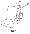
- This armrest 110 can be raised at the side of the seat back 120 when unused in order not to inhibit movement of passengers.
- an armrest providing increased effective vehicle interior space by making an armrest storage compartment compact
- patent document 1 While the armrest of the patent document 1 comfortably supports a passenger's arm in a used position, the armrest storage compartment becomes compact when the armrest is in an unused position, since the armrest can be folded toward the seat back and stowed upright at the side of the seat back. Therefore, the passengers' walk-through space between adjacent seats can be cleared when this type of armrest is used in a vehicle such as a station wagon.
- Patent document 1 Japanese Patent Laid-Open No. 2001-314277 (page 7 and 8, Figs. 2-4 )
- the armrest storage compartment becomes compact.
- this armrest requires a two-step operation of lowering the armrest to a horizontal position and rotating it before use. A need therefore exists to overcome this disadvantage.
- an armrest mounted to a side portion of a seat back of a vehicle seat comprising an armrest main body, and a pivot member supporting the armrest main body at a seat back side of the armrest main body, wherein the armrest main body is pivotally attached to the side portion of the seat back via the pivot member, and wherein the pivot member is skewed toward a vehicle rear area at a substantial angle relative to a widthwise horizontal axis of the seat as it extends from a base to a distal end, is provided.
- the armrest main body is fixed to the side portion of the seat back via the pivot member, and the pivot member is skewed toward the vehicle rear at the substantial angle relative to the widthwise horizontal axis of the seat as it extends from the base to the distal end.
- the armrest main body is at first positioned to extend in an outwardly diverging manner from the seat back as it extends from a base to a distal end in the used position, and the distal end approaches the side portion of the seat back and the armrest is finally stowed upright in the unused position.
- the armrest main body when unused, the armrest main body is stowed closer to the seat back such that the aisle width between adjacent seats is increased and the passengers' walk-through space is cleared. In addition, the armrest main body does not approach a seating space too much so as to support a passenger's arm at a comfortable position.
- the side portion of the seat back preferably has a slant surface tilted inwardly at a substantial angle relative to a horizontal axis in a fore-aft direction of the vehicle as the slant surface extends from a front to a rear
- the pivot member is preferably mounted to the slant surface so as to be positioned at a substantial angle relative to the slant surface such that an inner side of the armrest is approximately parallel to the slant surface when the armrest is raised. Therefore, as when raised, the armrest main body moves toward a back side of the seat back and is positioned upright in close proximity to the slant surface, effective interior space is increased when the armrest main body is stowed.
- the angle between the pivot member and the slant surface the amount of travel to the used position of the armrest main body in a lateral direction and the positional relationship between the stowed armrest main body and the seat back can be adjusted.
- an angle between an axis of the pivot member and the slant surface is approximately 90 degrees, the armrest main body and the seat back can be located in close proximity to each other.
- an armrest mounted to a side portion of a seat back of a vehicle seat comprising an armrest main body, and a pivot member supporting the armrest main body at a seat back side of the armrest main body, wherein the armrest main body is pivotally attached to the side portion of the seat back via the pivot member, and wherein the pivot member is skewed vertically upward at a substantial angle relative to a widthwise horizontal axis of the seat as it extends from a base to a distal end, is provided.
- the armrest main body is fixed to the side portion of the seat back via the pivot member, and the pivot member is skewed vertically upward at the substantial angle relative to the widthwise horizontal axis of the seat as it extends from the base to the distal end.
- the armrest main body is at first positioned to extend in an outwardly diverging manner from the seat back as it extends from a base to a distal end in the used position, and the distal end approaches the side portion of the seat back and the armrest is finally stowed upright in the unused position.
- the armrest preferably comprises a surface approximately perpendicular to a vehicle floor opposite the seat back and a surface inclined toward the seat back when the armrest is raised at the side of the seat back, the surface inclined toward the seat back being on top of the surface approximately perpendicular. Therefore, when stowed at the side of the seat back the armrest does not intrude into vehicle interior space and sufficient walk-through space is maintained.
- the side portion of the seat back is preferably tilted inwardly as it extends from a substantial center to an upper part in front view, wherein an inner side of the armrest is tilted along the side portion of the seat back. Therefore, when stowed upright at the seat back side, the armrest main body is raised to be positioned in close proximity to the slant surface of the seat back and sufficient walk-through space is maintained.
- a vehicle seat comprising any of the armrests prescribed above and a seat back of the seat has the armrest mounted thereto, is provided.
- the armrest and vehicle seat including the same of various embodiment of the present invention, with a simple structure that the pivot member holding the armrest main body at the seat back side is tilted, when stowed upright at the side of the seat back the armrest main body is positioned closer to the seat back.
- an aisle width between adjacent seats is increased and sufficient walk-through space is maintained in the vehicle.
- the armrest main body since the armrest main body extends in an outwardly diverging manner from the seat in the used position, the armrest main body does not approach a seating space too much so as to have sufficient area to support arms and to be capable to support a passenger's arm at a comfortable position.
- the armrest is switchable between the stowed position and the used position in a single motion: more specifically, it is switchable to the used position simply by lowering the armrest main body and to the unused position simply by raising it. Therefore such an armrest is easy for passengers to use. Furthermore, as the armrest comprises few parts so as to be easy to assemble, the number of assembling steps is decreased and manufacturing cost is reduced.
- Figs. 1 through 5 illustrate an embodiment of the present invention.
- Fig. 1 is a pictorial view of an armrest and a seat
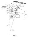
- Fig. 2 is a sectional view taken along line A-A of Fig. 1
- Fig. 3 is a front view of the armrest in an unused position and the seat
- Fig. 4 is a plan view of the armrest in the unused position and the seat
- Fig. 5 is a pictorial view of the armrests in a used position and in the unused position and the seats
- Fig. 6 is a sectional view of an alternative embodiment taken along line B-B of Fig. 1 .
- Fig. 1 illustrates a seat S having an armrest 10 according to an embodiment of the present invention as viewed from the side.
- the armrest 10 is illustrated in a stowed position.
- Reference numeral 30 indicates a seat portion of the seat S.
- the armrest 10 of this embodiment is mounted to a side portion of a seat back 20 of the seat S of an automobile.
- the armrest 10 comprises an armrest main body 11 and a pivot shaft 12 corresponding to a pivot member, and the armrest main body 11 is pivotally mounted to the seat back 20 via the pivot shaft 12.
- Fig. 2 is a sectional view taken along line A-A of Fig. 1 illustrating the seat S and the armrest 10 as cut along line A-A and viewed from above.
- Fig. 2 illustrates the construction of the armrest 10 and its attachment to the seat back 20.
- the armrest main body 11 comprises a frame 13 and a pad 14 integrally disposed to the frame 13.
- the outside of the pad 14 is covered with a skin member, not shown in Fig. 2 .
- the frame 13 and the pad 14 are formed with a hole 15.
- the hole 15 has a diameter sized to engage the pivot shaft 12.
- the armrest main body 11 is mounted to the seat back 20 via the pivot shaft 12.
- the seat back 20 comprises a back frame 21, a pad 22 and a bracket 23 to which the armrest is mounted.
- the outside of the pad 22 is covered with a skin member, not shown in Fig. 2 .
- the pivot shaft 12 is secured to the bracket 23 and projects therefrom.
- the pivot shaft 12 is provided with a pivot part 12a engaged with the hole 15 of the armrest main body 11 at the distal end.
- the pivot part 12a is made of resin and structured such that the armrest main body 11 can smoothly slide and rotate around the pivot shaft 12.
- a nut 12b is screwed to a distal end of the pivot part 12a and secures the armrest main body 11 to the pivot shaft 12 so as to prevent the armrest main body 11 from falling out of the pivot shaft 12.
- the lower side of Fig. 2 corresponds to the front side of the vehicle.
- the side portion of the seat back 20 has a slant surface 24 tilted at a substantial angle ⁇ 2 relative to a horizontal axis y in a fore-aft direction of the vehicle as the slant surface 24 extends from a front to a rear.
- the pivot shaft 12 is mounted to the slant surface 24 so as to be positioned at a substantial angle relative to the slant surface 24 such that an inner side of the armrest 10 is approximately parallel to the slant surface 24 when the armrest 10 is raised.
- the pivot shaft 12 of this embodiment is positioned at an angle of approximately 90 degrees relative to the slant surface 24.
- the pivot shaft 12 is skewed toward the vehicle rear at a substantial angle relative to a widthwise horizontal axis x of the seat S as it extends from a base to a distal end.
- the pivot shaft 12 of this embodiment is skewed horizontally at an angle ⁇ 1 relative to the horizontal axis x.
- the armrest main body 11 of this embodiment is mounted to the side portion of the seat back 20, and the pivot shaft 12 is tilted corresponding to the slant surface 24 of the side portion of the seat back 20.
- the armrest main body 11 moves toward a back side of the seat back 20 and is positioned upright in close proximity to the slant surface 24.
- the angle of the pivot shaft 12 relative to the slant surface 24 is not limited to 90 degrees; it may be another angle. By selecting the angle of the pivot shaft 12, the amount of travel to the used position of the armrest main body 11 in a lateral direction and the positional relationship between the stowed armrest main body 11 and the seat back 20 can be adjusted.
- the armrest main body 11 extends in a more outwardly diverging manner from the seat S and a spacing between the armrest main body 11 and the seat S in the used position increases. At the same time the armrest main body 11 is positioned closer to the seat back 20 in the stowed position.
- the armrest main body 11 becomes closer to the seat S in the used position, and is raised further away from the seat back 20 in the stowed position.
- Figs. 3 through 5 illustrate the armrests 10 in the used position and in the unused position.
- Fig. 3 illustrates the armrest 10 in the unused position: more specifically, it illustrates the armrest main body 11 being stowed upright at the side of the seat back 20.
- Fig. 3 illustrates the armrest 10 and the seat S viewed from the front of the vehicle.
- the side portion of the seat back 20 is tilted inwardly as it extends from a substantial center to an upper part in front view, and an inner side of the armrest main body 11 is tilted along the side portion of the seat back 20.
- the armrest main body 11 is positioned upright in close proximity to the side portion of the seat back 20.
- the armrest main body 11 is formed such that a surface 16 thereof opposite the seat back 20 is approximately perpendicular to a vehicle floor when mounted to the side portion of the seat back 20. Therefore, when stowed at the side of the seat back 20, the armrest main body 11 does not intrude into vehicle interior space and sufficient walk-through space is maintained.
- the armrest main body 11 of this embodiment is formed such that a top of the surface 16 approximately perpendicular is inclined toward the seat back 20 to correspond with an exterior shape of the seat back 20 when mounted to the side portion of the seat back 20.
- Fig. 4 illustrates the armrest main body 11 stowed at the side of the seat back 20, as viewed from above the seat S.
- a width w of the armrest main body 11 defines a width of a support surface for supporting a passenger's arm when the armrest 10 is in use.
- the slant surface 24 of the seat back 20 becomes steeper, that is, the angle ⁇ 2 becomes greater, the width w of the support surface of the armrest 10 becomes greater.
- Fig. 5 is a pictorial view of the armrests 10 in the used position and in the unused position in the vehicle.
- the armrests 10 of rear seats are in the used position and the armrests 10 of front seats are in the unused position.
- the seat back 20 of the seat S of this embodiment comprises the slant surface 24, to which the pivot shaft 12 is mounted so as to be skewed toward the vehicle rear at the substantial angle relative to the widthwise horizontal axis of the seat S as the pivot shaft 12 extends from the base to the distal end, and via this pivot shaft 12 the armrest main body 11 is pivotally attached to the side portion of the seat back 20.
- Reference numeral 17 in Fig. 5 indicates a support surface 17 on which a passenger puts his or her arm when the armrest 10 is used.
- the armrest main body 11 is formed such that the support surface 17 is positioned horizontally in the used position.
- the armrest main body 11 is raised at the side of the seat back 20 when the armrest 10 is not used.
- the armrest main body 11 is pivotally attached to the pivot shaft 12 being skewed toward the vehicle rear at a substantial angle relative to the widthwise horizontal axis of the seat S as the pivot shaft 12 extends from the base to the distal end, the armrest main body 11 moves toward the back side of the seat back 20 and is positioned in close proximity to the side portion of the seat back 20 and stowed.
- the armrest main body 11 is formed such that the surface 16 thereof opposite the seat back 20 is approximately perpendicular to the vehicle floor when mounted to the side portion of the seat back 20, the armrest main body 11 does not intrude into vehicle interior space. Therefore, the overall width of the seat back 20 is reduced and sufficient walk-through space 40 is maintained.
- the distance between a center of the seat portion 30 and a lateral side of the armrest main body 11 is 331 mm (arrow a) in the used position of the armrest 10, and is 277 mm (arrow b) when the armrest 10 is stowed at the side of the seat back 20.
- the armrest 10 of this embodiment is stowed 54mm more compactly in width in the stowed position than in the used position, and the width of the walk-through space 40 is 108 mm greater when both armrests 10 of adjacent seats are used than when they are stowed.
- Fig. 6 illustrates another embodiment.
- the same or similar reference numerals are applied to the same or similar members and arrangements as or to the previous embodiment, and their description will be omitted or simplified.
- Fig. 6 is a sectional view taken along line B-B of Fig. 1 as the seat S and the armrest 10 are cut along line B-B and viewed from the front.
- the pivot shaft 12 of the previous embodiment is skewed horizontally at the angle ⁇ 1 relative to the widthwise horizontal axis x of the seat as it extends from the base to the distal end
- a pivot shaft 12 of this embodiment is skewed vertically upward at a substantial angle relative to the widthwise horizontal axis x of the seat as it extends from the base to the distal end.
- the pivot shaft 12 of this embodiment is mounted so as to be skewed at an angle ⁇ 3 relative to the horizontal axis x, and the armrest main body 11 extends in an outwardly diverging manner from the seat S when in use.
- the armrest main body 11 moves toward the seat back 20 and is raised upright to be stowed in close proximity to the side portion of the seat back 20.
- the side portion of the seat back 20 is tilted inwardly as it extends from a substantial center to an upper part in front view such that the armrest main body 11 does not interfere with the side portion of the seat back 20 when raised.
- the seat back 20 may be configured to have no such slant surfaces.
- the armrest main body 11 is configured to have a shape that does not interfere with the side portion of the seat back 20 when raised.
Landscapes
- Engineering & Computer Science (AREA)
- Aviation & Aerospace Engineering (AREA)
- Transportation (AREA)
- Mechanical Engineering (AREA)
- Seats For Vehicles (AREA)
Abstract
An armrest, having sufficient area to support arms, to support arms at a comfortable position, capable of being stowed compactly to provide aisle width sufficient for passengers' walk-through, and capable of returning from a stowed position to a used position in a single motion, and a vehicle seat including the same, are provided.
[MEANS FOR SOLVING PROBLEMS]
An armrest 10 mounted to a side portion of a seat back 20 of a vehicle seat S, including an armrest main body 11, and a pivot member 12 supporting the armrest main body 11 at the seat back 20 side of the armrest main body 11, wherein the armrest main body 11 is pivotally attached to the side portion of the seat back 20 via the pivot member 12, and wherein the pivot member 12 is skewed toward the vehicle rear at a substantial angle θ1 relative to a widthwise horizontal axis x of the seat S as it extends from a base to a distal end.
Description
- The present invention relates to an armrest and a vehicle seat including the same, and is particularly related to a foldable armrest which is moveable between a raised position and a forward lowered position relative to a seat back and a vehicle seat including the same.
- An armrest for a seat of a vehicle, for example an automobile, such as a
foldable armrest 110 shown inFig. 7 , is known. Thisarmrest 110 can be raised at the side of the seat back 120 when unused in order not to inhibit movement of passengers. - To move between the front and rear seating positions in a station wagon, passengers typically walk through an aisle between adjacent seats. However, when the aisle is narrow, the armrests obstruct the aisle and inhibit passengers' smooth walk-through.
- In order to overcome this disadvantage, an armrest providing increased effective vehicle interior space by making an armrest storage compartment compact, is proposed (for example, patent document 1). While the armrest of the patent document 1 comfortably supports a passenger's arm in a used position, the armrest storage compartment becomes compact when the armrest is in an unused position, since the armrest can be folded toward the seat back and stowed upright at the side of the seat back. Therefore, the passengers' walk-through space between adjacent seats can be cleared when this type of armrest is used in a vehicle such as a station wagon.
- Patent document 1: Japanese Patent Laid-Open No.
2001-314277 Figs. 2-4 ) - According to the prior art disclosed in the patent document 1, the armrest storage compartment becomes compact. However, this armrest requires a two-step operation of lowering the armrest to a horizontal position and rotating it before use. A need therefore exists to overcome this disadvantage.
- It therefore is an object of the present invention to provide an armrest having sufficient area to support arms, supporting arms at a comfortable position, and being stowed compactly to provide a sufficient aisle width for passengers' walk-through, and capable of returning from a stowed position to a used position in a single motion.
It is another object of the present invention to provide a vehicle seat including the above armrest. - To achieve the objects, according to one embodiment of the present invention, an armrest mounted to a side portion of a seat back of a vehicle seat, comprising an armrest main body, and a pivot member supporting the armrest main body at a seat back side of the armrest main body, wherein the armrest main body is pivotally attached to the side portion of the seat back via the pivot member, and wherein the pivot member is skewed toward a vehicle rear area at a substantial angle relative to a widthwise horizontal axis of the seat as it extends from a base to a distal end, is provided.
- As described above, according to the armrest for various embodiments of the present invention, the armrest main body is fixed to the side portion of the seat back via the pivot member, and the pivot member is skewed toward the vehicle rear at the substantial angle relative to the widthwise horizontal axis of the seat as it extends from the base to the distal end. Thus, when rotated at the seat back side, the armrest main body is at first positioned to extend in an outwardly diverging manner from the seat back as it extends from a base to a distal end in the used position, and the distal end approaches the side portion of the seat back and the armrest is finally stowed upright in the unused position.
- Therefore, when unused, the armrest main body is stowed closer to the seat back such that the aisle width between adjacent seats is increased and the passengers' walk-through space is cleared.
In addition, the armrest main body does not approach a seating space too much so as to support a passenger's arm at a comfortable position. - More specifically, the side portion of the seat back preferably has a slant surface tilted inwardly at a substantial angle relative to a horizontal axis in a fore-aft direction of the vehicle as the slant surface extends from a front to a rear, the pivot member is preferably mounted to the slant surface so as to be positioned at a substantial angle relative to the slant surface such that an inner side of the armrest is approximately parallel to the slant surface when the armrest is raised.
Therefore, as when raised, the armrest main body moves toward a back side of the seat back and is positioned upright in close proximity to the slant surface, effective interior space is increased when the armrest main body is stowed.
In addition, by selecting the angle between the pivot member and the slant surface, the amount of travel to the used position of the armrest main body in a lateral direction and the positional relationship between the stowed armrest main body and the seat back can be adjusted. - Furthermore, if an angle between an axis of the pivot member and the slant surface is approximately 90 degrees, the armrest main body and the seat back can be located in close proximity to each other.
- To achieve the objects, according to another embodiment of the present invention, an armrest mounted to a side portion of a seat back of a vehicle seat, comprising an armrest main body, and a pivot member supporting the armrest main body at a seat back side of the armrest main body, wherein the armrest main body is pivotally attached to the side portion of the seat back via the pivot member, and wherein the pivot member is skewed vertically upward at a substantial angle relative to a widthwise horizontal axis of the seat as it extends from a base to a distal end, is provided.
- As described above, according to the armrest of various embodiments of the present invention, the armrest main body is fixed to the side portion of the seat back via the pivot member, and the pivot member is skewed vertically upward at the substantial angle relative to the widthwise horizontal axis of the seat as it extends from the base to the distal end. Thus, when rotated at the seat back side, the armrest main body is at first positioned to extend in an outwardly diverging manner from the seat back as it extends from a base to a distal end in the used position, and the distal end approaches the side portion of the seat back and the armrest is finally stowed upright in the unused position.
- In addition, the armrest preferably comprises a surface approximately perpendicular to a vehicle floor opposite the seat back and a surface inclined toward the seat back when the armrest is raised at the side of the seat back, the surface inclined toward the seat back being on top of the surface approximately perpendicular. Therefore, when stowed at the side of the seat back the armrest does not intrude into vehicle interior space and sufficient walk-through space is maintained.
- Further, the side portion of the seat back is preferably tilted inwardly as it extends from a substantial center to an upper part in front view, wherein an inner side of the armrest is tilted along the side portion of the seat back. Therefore, when stowed upright at the seat back side, the armrest main body is raised to be positioned in close proximity to the slant surface of the seat back and sufficient walk-through space is maintained.
- Furthermore, to achieve the objects, according to yet another embodiment of the present invention, a vehicle seat comprising any of the armrests prescribed above and a seat back of the seat has the armrest mounted thereto, is provided.
- According to the armrest and vehicle seat including the same of various embodiment of the present invention, with a simple structure that the pivot member holding the armrest main body at the seat back side is tilted, when stowed upright at the side of the seat back the armrest main body is positioned closer to the seat back. As a result, an aisle width between adjacent seats is increased and sufficient walk-through space is maintained in the vehicle.
Furthermore, since the armrest main body extends in an outwardly diverging manner from the seat in the used position, the armrest main body does not approach a seating space too much so as to have sufficient area to support arms and to be capable to support a passenger's arm at a comfortable position. - In addition, while the armrest according to various embodiments of the present invention has a space-saving design, the armrest is switchable between the stowed position and the used position in a single motion: more specifically, it is switchable to the used position simply by lowering the armrest main body and to the unused position simply by raising it. Therefore such an armrest is easy for passengers to use.
Furthermore, as the armrest comprises few parts so as to be easy to assemble, the number of assembling steps is decreased and manufacturing cost is reduced. -
-
Fig. 1 is a pictorial view of an armrest and a seat according to an embodiment of the present invention; -
Fig. 2 is a sectional view taken along line A-A ofFig. 1 ; -
Fig. 3 is a front view of the armrest in an unused position and the seat; -
Fig. 4 is a plan view of the armrest in the unused position and the seat; -
Fig. 5 is a pictorial view of the armrests in a used position and in the unused position and the seats; -
Fig. 6 is a sectional view of an alternative embodiment taken along line B-B ofFig. 1 ; -
Fig. 7 is a pictorial view of a prior art embodiment. -
- 10
- armrest
- 11
- armrest main body
- 12
- pivot shaft (pivot member)
- 12a
- pivot part
- 12b
- nut
- 13
- frame
- 14
- pad
- 15
- hole
- 16
- surface
- 17
- support surface
- 20
- seat back
- 21
- back frame
- 22
- pad
- 23
- bracket
- 24
- slant surface
- 30
- seat portion
- 40
- walk-through space
- S
- seat
- x
- widthwise horizontal axis of the seat
- y
- horizontal axis in the fore-aft direction of the vehicle
- θ1, θ3
- angle between the widthwise horizontal axis of the seat and the pivot shaft
- θ2
- angle between the horizontal axis in the fore-aft direction of the vehicle and the slant surface of the seat back
- An embodiment of the present invention will be described with reference to the accompanying drawings. It is to be understood that the present invention is not limited to the specific construction and arrangement of parts described below, and variations may be made without departing from the spirit and scope of the invention.
-
Figs. 1 through 5 illustrate an embodiment of the present invention.Fig. 1 is a pictorial view of an armrest and a seat,Fig. 2 is a sectional view taken along line A-A ofFig. 1 ,Fig. 3 is a front view of the armrest in an unused position and the seat,Fig. 4 is a plan view of the armrest in the unused position and the seat,Fig. 5 is a pictorial view of the armrests in a used position and in the unused position and the seats, andFig. 6 is a sectional view of an alternative embodiment taken along line B-B ofFig. 1 . -
Fig. 1 illustrates a seat S having an armrest 10 according to an embodiment of the present invention as viewed from the side. InFig. 1 thearmrest 10 is illustrated in a stowed position.Reference numeral 30 indicates a seat portion of the seat S. - The
armrest 10 of this embodiment is mounted to a side portion of a seat back 20 of the seat S of an automobile.
Thearmrest 10 comprises an armrestmain body 11 and apivot shaft 12 corresponding to a pivot member, and the armrestmain body 11 is pivotally mounted to the seat back 20 via thepivot shaft 12. -
Fig. 2 is a sectional view taken along line A-A ofFig. 1 illustrating the seat S and the armrest 10 as cut along line A-A and viewed from above.Fig. 2 illustrates the construction of thearmrest 10 and its attachment to the seat back 20. - The armrest
main body 11 comprises aframe 13 and apad 14 integrally disposed to theframe 13. The outside of thepad 14 is covered with a skin member, not shown inFig. 2 . - The
frame 13 and thepad 14 are formed with ahole 15. Thehole 15 has a diameter sized to engage thepivot shaft 12.
The armrestmain body 11 is mounted to the seat back 20 via thepivot shaft 12. - The seat back 20 comprises a
back frame 21, apad 22 and abracket 23 to which the armrest is mounted. The outside of thepad 22 is covered with a skin member, not shown inFig. 2 . - The
pivot shaft 12 is secured to thebracket 23 and projects therefrom.
Thepivot shaft 12 is provided with apivot part 12a engaged with thehole 15 of the armrestmain body 11 at the distal end. Thepivot part 12a is made of resin and structured such that the armrestmain body 11 can smoothly slide and rotate around thepivot shaft 12. Anut 12b is screwed to a distal end of thepivot part 12a and secures the armrestmain body 11 to thepivot shaft 12 so as to prevent the armrestmain body 11 from falling out of thepivot shaft 12. - The lower side of
Fig. 2 corresponds to the front side of the vehicle. As illustrated in the figure, the side portion of the seat back 20 has aslant surface 24 tilted at a substantial angle θ2 relative to a horizontal axis y in a fore-aft direction of the vehicle as theslant surface 24 extends from a front to a rear. - The
pivot shaft 12 is mounted to theslant surface 24 so as to be positioned at a substantial angle relative to theslant surface 24 such that an inner side of thearmrest 10 is approximately parallel to theslant surface 24 when thearmrest 10 is raised. Thepivot shaft 12 of this embodiment is positioned at an angle of approximately 90 degrees relative to theslant surface 24. - Regarding a positional relationship between the seat S and the
pivot shaft 12, thepivot shaft 12 is skewed toward the vehicle rear at a substantial angle relative to a widthwise horizontal axis x of the seat S as it extends from a base to a distal end. Thepivot shaft 12 of this embodiment is skewed horizontally at an angle θ1 relative to the horizontal axis x. - The armrest
main body 11 of this embodiment is mounted to the side portion of the seat back 20, and thepivot shaft 12 is tilted corresponding to theslant surface 24 of the side portion of the seat back 20. Thus when the armrestmain body 11 is raised at the side of the seat back 20, the armrestmain body 11 moves toward a back side of the seat back 20 and is positioned upright in close proximity to theslant surface 24. - The angle of the
pivot shaft 12 relative to theslant surface 24 is not limited to 90 degrees; it may be another angle. By selecting the angle of thepivot shaft 12, the amount of travel to the used position of the armrestmain body 11 in a lateral direction and the positional relationship between the stowed armrestmain body 11 and the seat back 20 can be adjusted. - As the angle between the
pivot shaft 12 and theslant surface 24 becomes more acute, that is, the angle θ1 becomes greater, the armrestmain body 11 extends in a more outwardly diverging manner from the seat S and a spacing between the armrestmain body 11 and the seat S in the used position increases. At the same time the armrestmain body 11 is positioned closer to the seat back 20 in the stowed position. - As the angle between the
pivot shaft 12 and theslant surface 24 becomes more obtuse, that is, the angle θ1 becomes smaller, the armrestmain body 11 becomes closer to the seat S in the used position, and is raised further away from the seat back 20 in the stowed position. -
Figs. 3 through 5 illustrate thearmrests 10 in the used position and in the unused position.
Fig. 3 illustrates the armrest 10 in the unused position: more specifically, it illustrates the armrestmain body 11 being stowed upright at the side of the seat back 20.Fig. 3 illustrates thearmrest 10 and the seat S viewed from the front of the vehicle. - As illustrated in the figure, the side portion of the seat back 20 is tilted inwardly as it extends from a substantial center to an upper part in front view, and an inner side of the armrest
main body 11 is tilted along the side portion of the seat back 20. Thus, when stowed, the armrestmain body 11 is positioned upright in close proximity to the side portion of the seat back 20. - The armrest
main body 11 is formed such that asurface 16 thereof opposite the seat back 20 is approximately perpendicular to a vehicle floor when mounted to the side portion of the seat back 20. Therefore, when stowed at the side of the seat back 20, the armrestmain body 11 does not intrude into vehicle interior space and sufficient walk-through space is maintained. The armrestmain body 11 of this embodiment is formed such that a top of thesurface 16 approximately perpendicular is inclined toward the seat back 20 to correspond with an exterior shape of the seat back 20 when mounted to the side portion of the seat back 20. -
Fig. 4 illustrates the armrestmain body 11 stowed at the side of the seat back 20, as viewed from above the seat S.
A width w of the armrestmain body 11 defines a width of a support surface for supporting a passenger's arm when thearmrest 10 is in use.
As theslant surface 24 of the seat back 20 becomes steeper, that is, the angle θ2 becomes greater, the width w of the support surface of thearmrest 10 becomes greater. -
Fig. 5 is a pictorial view of thearmrests 10 in the used position and in the unused position in the vehicle.
InFig. 5 , thearmrests 10 of rear seats are in the used position and thearmrests 10 of front seats are in the unused position.
The seat back 20 of the seat S of this embodiment comprises theslant surface 24, to which thepivot shaft 12 is mounted so as to be skewed toward the vehicle rear at the substantial angle relative to the widthwise horizontal axis of the seat S as thepivot shaft 12 extends from the base to the distal end, and via thispivot shaft 12 the armrestmain body 11 is pivotally attached to the side portion of the seat back 20. Therefore, since the armrestmain body 11 extends in an outwardly diverging manner from the seat S in the used position, the armrestmain body 11 does not approach a seating space too much so as to support a passenger's arm at a comfortable position.
Reference numeral 17 inFig. 5 indicates asupport surface 17 on which a passenger puts his or her arm when thearmrest 10 is used. The armrestmain body 11 is formed such that thesupport surface 17 is positioned horizontally in the used position. - The armrest
main body 11 is raised at the side of the seat back 20 when thearmrest 10 is not used. In this case, since the armrestmain body 11 is pivotally attached to thepivot shaft 12 being skewed toward the vehicle rear at a substantial angle relative to the widthwise horizontal axis of the seat S as thepivot shaft 12 extends from the base to the distal end, the armrestmain body 11 moves toward the back side of the seat back 20 and is positioned in close proximity to the side portion of the seat back 20 and stowed.
Furthermore, since the armrestmain body 11 is formed such that thesurface 16 thereof opposite the seat back 20 is approximately perpendicular to the vehicle floor when mounted to the side portion of the seat back 20, the armrestmain body 11 does not intrude into vehicle interior space. Therefore, the overall width of the seat back 20 is reduced and sufficient walk-through space 40 is maintained. - In this embodiment, as illustrated in
Fig. 5 , the distance between a center of theseat portion 30 and a lateral side of the armrestmain body 11 is 331 mm (arrow a) in the used position of the armrest 10, and is 277 mm (arrow b) when thearmrest 10 is stowed at the side of the seat back 20. Thus, thearmrest 10 of this embodiment is stowed 54mm more compactly in width in the stowed position than in the used position, and the width of the walk-through space 40 is 108 mm greater when botharmrests 10 of adjacent seats are used than when they are stowed. -
Fig. 6 illustrates another embodiment. In this embodiment, the same or similar reference numerals are applied to the same or similar members and arrangements as or to the previous embodiment, and their description will be omitted or simplified.
Fig. 6 is a sectional view taken along line B-B ofFig. 1 as the seat S and the armrest 10 are cut along line B-B and viewed from the front.
While thepivot shaft 12 of the previous embodiment is skewed horizontally at the angle θ1 relative to the widthwise horizontal axis x of the seat as it extends from the base to the distal end, apivot shaft 12 of this embodiment is skewed vertically upward at a substantial angle relative to the widthwise horizontal axis x of the seat as it extends from the base to the distal end. - More specifically, the
pivot shaft 12 of this embodiment is mounted so as to be skewed at an angle θ3 relative to the horizontal axis x, and the armrestmain body 11 extends in an outwardly diverging manner from the seat S when in use. When the armrestmain body 11 is being stowed, the armrestmain body 11 moves toward the seat back 20 and is raised upright to be stowed in close proximity to the side portion of the seat back 20. - In this embodiment, the side portion of the seat back 20 is tilted inwardly as it extends from a substantial center to an upper part in front view such that the armrest
main body 11 does not interfere with the side portion of the seat back 20 when raised. - Though the side portion of the seat back 20 has the
slant surface 24 or is tilted inwardly from the substantial center to the upper part in front view in the embodiments described above, the seat back 20 may be configured to have no such slant surfaces. In this case, the armrestmain body 11 is configured to have a shape that does not interfere with the side portion of the seat back 20 when raised.
Claims (7)
- An armrest mounted to a side portion of a seat back of a vehicle seat, comprising:an armrest main body; anda pivot member supporting the armrest main body at a seat back side of the armrest main body;wherein the armrest main body is pivotally attached to the side portion of the seat back via the pivot member; and
wherein the pivot member is skewed toward a vehicle rear area at a substantial angle relative to a widthwise horizontal axis of the seat as it extends from a base to a distal end. - The armrest according to claim 1, wherein the side portion of the seat back has a slant surface tilted inwardly at a substantial angle relative to a horizontal axis in a fore-aft direction of the vehicle as the slant surface extends from a front to a rear;
wherein the pivot member is mounted to the slant surface so as to be positioned at a substantial angle relative to the slant surface such that an inner side of the armrest is approximately parallel to the slant surface when the armrest is raised. - The armrest according to claim 2, wherein an angle between an axis of the pivot member and the slant surface is approximately 90 degrees.
- An armrest mounted to a side portion of a seat back of a vehicle seat, comprising:an armrest main body; anda pivot member supporting the armrest main body at a seat back side of the armrest main body;wherein the armrest main body is pivotally attached to the side portion of the seat back via the pivot member; and
wherein the pivot member is skewed vertically upward at a substantial angle relative to a widthwise horizontal axis of the seat as it extends from a base to a distal end. - The armrest according to claim 1 or claim 4, wherein the armrest comprises a surface approximately perpendicular to a vehicle floor opposite the seat back and a surface inclined toward the seat back when the armrest is raised at the side of the seat back, the surface inclined toward the seatback being on top of the surface approximately perpendicular.
- The armrest according to claim 1 or claim 4, wherein the side portion of the seat back is tilted inwardly as it extends from a substantial center to an upper part in front view, wherein an inner side of the armrest is tilted along the side portion of the seat back.
- A vehicle seat comprising the armrest as in any of the preceding claims and a seat back of the seat has the armrest mounted thereto.
Applications Claiming Priority (2)
| Application Number | Priority Date | Filing Date | Title |
|---|---|---|---|
| JP2005248464 | 2005-08-29 | ||
| PCT/JP2006/316900 WO2007026660A1 (en) | 2005-08-29 | 2006-08-28 | Arm rest and vehicle seating seat with arm rest |
Publications (2)
| Publication Number | Publication Date |
|---|---|
| EP1938714A1 true EP1938714A1 (en) | 2008-07-02 |
| EP1938714A4 EP1938714A4 (en) | 2009-11-18 |
Family
ID=37808750
Family Applications (1)
| Application Number | Title | Priority Date | Filing Date |
|---|---|---|---|
| EP06796884A Withdrawn EP1938714A4 (en) | 2005-08-29 | 2006-08-28 | Arm rest and vehicle seating seat with arm rest |
Country Status (5)
| Country | Link |
|---|---|
| US (1) | US7731290B1 (en) |
| EP (1) | EP1938714A4 (en) |
| JP (1) | JP4891248B2 (en) |
| CN (1) | CN101252857B (en) |
| WO (1) | WO2007026660A1 (en) |
Cited By (1)
| Publication number | Priority date | Publication date | Assignee | Title |
|---|---|---|---|---|
| CN109969054A (en) * | 2017-11-30 | 2019-07-05 | 佛吉亚内饰系统有限责任公司 | Seat system for vehicle interior |
Families Citing this family (7)
| Publication number | Priority date | Publication date | Assignee | Title |
|---|---|---|---|---|
| JP5136031B2 (en) * | 2007-12-06 | 2013-02-06 | トヨタ紡織株式会社 | Armrest mounting structure for vehicle seat |
| JP5381092B2 (en) * | 2008-12-26 | 2014-01-08 | マツダ株式会社 | Vehicle seat device |
| JP6964557B2 (en) * | 2018-06-05 | 2021-11-10 | 株式会社オートネットワーク技術研究所 | Armrest |
| JP7205760B2 (en) * | 2019-01-31 | 2023-01-17 | スズキ株式会社 | moving body |
| JP7179152B2 (en) * | 2019-03-11 | 2022-11-28 | 株式会社オートネットワーク技術研究所 | Armrests and seats with armrests |
| CN115245437B (en) * | 2021-04-26 | 2025-03-21 | 上海荣泰健康科技股份有限公司 | Intelligent massage chair |
| WO2022227197A1 (en) * | 2021-04-26 | 2022-11-03 | 上海荣泰健康科技股份有限公司 | Intelligent massage chair |
Family Cites Families (22)
| Publication number | Priority date | Publication date | Assignee | Title |
|---|---|---|---|---|
| US3550958A (en) * | 1968-09-16 | 1970-12-29 | Reuben J Krein | Movable arm rest |
| US4159145A (en) * | 1977-08-29 | 1979-06-26 | Flexsteel Industries, Inc. | Retractible armrest support |
| US4216994A (en) * | 1978-06-26 | 1980-08-12 | Inter Royal Corporation | Tablet side arm for chairs |
| CH660840A5 (en) * | 1983-02-28 | 1987-05-29 | Intercollection Dev S A | Chair |
| DE3512953C2 (en) * | 1985-04-11 | 1987-04-02 | Daimler-Benz Ag, 7000 Stuttgart | Seat facing the aisle of a bus |
| US5104191A (en) * | 1991-02-28 | 1992-04-14 | Hoover Universal, Inc. | Articulated torsion arm rest for a vehicle seat assembly |
| US5320414A (en) * | 1992-07-16 | 1994-06-14 | Prince Corporation | Articulated armrest |
| US5290092A (en) | 1992-10-23 | 1994-03-01 | General Motors Corporation | Stowaway armrest |
| JP3406630B2 (en) * | 1992-12-22 | 2003-05-12 | テイ・エス テック株式会社 | Table mounting device that can also be used as an armrest |
| US5597209A (en) | 1995-05-11 | 1997-01-28 | Hoover Universal, Inc. | Adjustable vehicle seat armrest with a ratchet |
| CN2257668Y (en) * | 1996-03-08 | 1997-07-16 | 欣业企业股份有限公司 | Adjustment device for chair armrests |
| DE19751437A1 (en) * | 1997-11-20 | 1999-05-27 | Volkswagen Ag | Vehicle seat with foldaway armrest |
| US6217119B1 (en) * | 1999-10-21 | 2001-04-17 | Paccar Inc | Extendable armrest assembly for a seat |
| JP2001197958A (en) * | 2000-01-18 | 2001-07-24 | Johnson Controls Automotive Systems Corp | Vehicle seat with armrest |
| JP2001314277A (en) * | 2000-05-11 | 2001-11-13 | T S Tec Kk | Armrest |
| US6471297B1 (en) * | 2000-08-25 | 2002-10-29 | Magna Seating Systems, Inc. | Pivotal and retractable armrest assembly |
| US6467847B2 (en) | 2001-01-19 | 2002-10-22 | Johnson Controls Technology Company | Comfort armrest with memory |
| DE10338414A1 (en) * | 2002-08-19 | 2005-03-24 | Grammer Ag | armrest |
| US7004546B1 (en) * | 2005-03-30 | 2006-02-28 | Cessna Aircraft Company | Stowable chair armrest |
| JP4415899B2 (en) | 2005-05-11 | 2010-02-17 | トヨタ自動車株式会社 | Vehicle armrest |
| JP4852912B2 (en) * | 2005-07-15 | 2012-01-11 | 株式会社豊田自動織機 | Industrial vehicle |
| US7255402B1 (en) * | 2006-03-28 | 2007-08-14 | Gm Global Technology Operations, Inc. | Concealed armrest |
-
2006
- 2006-08-28 WO PCT/JP2006/316900 patent/WO2007026660A1/en not_active Ceased
- 2006-08-28 JP JP2007533233A patent/JP4891248B2/en not_active Expired - Fee Related
- 2006-08-28 CN CN2006800319858A patent/CN101252857B/en not_active Expired - Fee Related
- 2006-08-28 EP EP06796884A patent/EP1938714A4/en not_active Withdrawn
- 2006-08-28 US US12/064,986 patent/US7731290B1/en active Active
Cited By (1)
| Publication number | Priority date | Publication date | Assignee | Title |
|---|---|---|---|---|
| CN109969054A (en) * | 2017-11-30 | 2019-07-05 | 佛吉亚内饰系统有限责任公司 | Seat system for vehicle interior |
Also Published As
| Publication number | Publication date |
|---|---|
| JPWO2007026660A1 (en) | 2009-03-05 |
| CN101252857B (en) | 2010-10-13 |
| CN101252857A (en) | 2008-08-27 |
| US7731290B1 (en) | 2010-06-08 |
| EP1938714A4 (en) | 2009-11-18 |
| JP4891248B2 (en) | 2012-03-07 |
| WO2007026660A1 (en) | 2007-03-08 |
Similar Documents
| Publication | Publication Date | Title |
|---|---|---|
| US5290092A (en) | Stowaway armrest | |
| US6811200B2 (en) | Seat device for vehicle | |
| JP5349329B2 (en) | Motor vehicle seat with foldable back with table forming member and motor vehicle with such a seat | |
| US10457170B2 (en) | Flexible motor vehicle work surface for laptops and tablets | |
| US10457171B2 (en) | Flexible motor vehicle work surface for laptops and tablets | |
| US7059681B2 (en) | Headrest for vehicle seat | |
| US20080079278A1 (en) | Dual Sliding Center Console | |
| US20190031114A1 (en) | Flexible motor vehicle work surface for laptops and tablets | |
| US5749629A (en) | Console assembly with adjustable armrest | |
| CA2687137A1 (en) | Deployable center armrest | |
| US20050017561A1 (en) | Seat, seat recliner mechanism, and seat recliner system | |
| JPH04221513A (en) | Seat headrest | |
| FR3066446A1 (en) | INTERIOR VEHICLE PLANNING | |
| US20050012367A1 (en) | Seat system | |
| US7731290B1 (en) | Armrest and vehicle seat including the same | |
| US10118511B2 (en) | Seat device for vehicle | |
| JP5381092B2 (en) | Vehicle seat device | |
| US20090167070A1 (en) | Armrest For Motor Vehicle Seat Assembly | |
| JP2006141855A (en) | Seat back | |
| CN216002425U (en) | Rear seat of vehicle and vehicle | |
| JP3738102B2 (en) | Car backseat | |
| JP4569823B2 (en) | Vehicle seat | |
| KR20240021384A (en) | Armrest device with level maintenance function | |
| JPH11237A (en) | Armrest for vehicle | |
| JP4078509B2 (en) | Armrest mounting structure for vehicle seat |
Legal Events
| Date | Code | Title | Description |
|---|---|---|---|
| PUAI | Public reference made under article 153(3) epc to a published international application that has entered the european phase |
Free format text: ORIGINAL CODE: 0009012 |
|
| 17P | Request for examination filed |
Effective date: 20080314 |
|
| AK | Designated contracting states |
Kind code of ref document: A1 Designated state(s): AT BE BG CH CY CZ DE DK EE ES FI FR GB GR HU IE IS IT LI LT LU LV MC NL PL PT RO SE SI SK TR |
|
| A4 | Supplementary search report drawn up and despatched |
Effective date: 20091021 |
|
| STAA | Information on the status of an ep patent application or granted ep patent |
Free format text: STATUS: THE APPLICATION IS DEEMED TO BE WITHDRAWN |
|
| 18D | Application deemed to be withdrawn |
Effective date: 20100120 |