EP1937557B1 - Method and machine for packing groups of products arranged in one or more layers - Google Patents
Method and machine for packing groups of products arranged in one or more layers Download PDFInfo
- Publication number
- EP1937557B1 EP1937557B1 EP06810034A EP06810034A EP1937557B1 EP 1937557 B1 EP1937557 B1 EP 1937557B1 EP 06810034 A EP06810034 A EP 06810034A EP 06810034 A EP06810034 A EP 06810034A EP 1937557 B1 EP1937557 B1 EP 1937557B1
- Authority
- EP
- European Patent Office
- Prior art keywords
- conveyors
- tilting drum
- product
- folding
- drum
- Prior art date
- Legal status (The legal status is an assumption and is not a legal conclusion. Google has not performed a legal analysis and makes no representation as to the accuracy of the status listed.)
- Not-in-force
Links
- 238000012856 packing Methods 0.000 title claims abstract description 53
- 238000000034 method Methods 0.000 title claims abstract description 12
- 230000005540 biological transmission Effects 0.000 claims description 9
- 230000009467 reduction Effects 0.000 claims description 9
- 238000007789 sealing Methods 0.000 claims description 9
- 230000033001 locomotion Effects 0.000 claims description 8
- 230000008878 coupling Effects 0.000 claims description 3
- 238000010168 coupling process Methods 0.000 claims description 3
- 238000005859 coupling reaction Methods 0.000 claims description 3
- 230000000717 retained effect Effects 0.000 claims description 3
- 230000001360 synchronised effect Effects 0.000 claims description 3
- 238000013519 translation Methods 0.000 claims description 3
- 230000009471 action Effects 0.000 claims description 2
- 238000010438 heat treatment Methods 0.000 claims description 2
- 238000011144 upstream manufacturing Methods 0.000 claims description 2
- 230000000875 corresponding effect Effects 0.000 claims 6
- 230000002596 correlated effect Effects 0.000 claims 1
- 230000003068 static effect Effects 0.000 claims 1
- 238000012546 transfer Methods 0.000 description 4
- 238000010276 construction Methods 0.000 description 2
- 239000003292 glue Substances 0.000 description 2
- 230000006872 improvement Effects 0.000 description 2
- 230000004048 modification Effects 0.000 description 2
- 238000012986 modification Methods 0.000 description 2
- 230000008569 process Effects 0.000 description 2
- 230000003134 recirculating effect Effects 0.000 description 2
- 125000004122 cyclic group Chemical group 0.000 description 1
- 230000003247 decreasing effect Effects 0.000 description 1
- 230000000694 effects Effects 0.000 description 1
- 238000003780 insertion Methods 0.000 description 1
- 230000037431 insertion Effects 0.000 description 1
- 239000000463 material Substances 0.000 description 1
- 230000007246 mechanism Effects 0.000 description 1
- 230000008092 positive effect Effects 0.000 description 1
- 239000007787 solid Substances 0.000 description 1
- 230000007704 transition Effects 0.000 description 1
Images


Classifications
-
- B—PERFORMING OPERATIONS; TRANSPORTING
- B65—CONVEYING; PACKING; STORING; HANDLING THIN OR FILAMENTARY MATERIAL
- B65B—MACHINES, APPARATUS OR DEVICES FOR, OR METHODS OF, PACKAGING ARTICLES OR MATERIALS; UNPACKING
- B65B11/00—Wrapping, e.g. partially or wholly enclosing, articles or quantities of material, in strips, sheets or blanks, of flexible material
- B65B11/06—Wrapping articles, or quantities of material, by conveying wrapper and contents in common defined paths
- B65B11/38—Wrapping articles, or quantities of material, by conveying wrapper and contents in common defined paths in a combination of straight and curved paths
- B65B11/40—Wrapping articles, or quantities of material, by conveying wrapper and contents in common defined paths in a combination of straight and curved paths to fold the wrappers in tubular form about contents
- B65B11/42—Wrapping articles, or quantities of material, by conveying wrapper and contents in common defined paths in a combination of straight and curved paths to fold the wrappers in tubular form about contents and then to form closing folds of similar form at opposite ends of the tube
-
- B—PERFORMING OPERATIONS; TRANSPORTING
- B65—CONVEYING; PACKING; STORING; HANDLING THIN OR FILAMENTARY MATERIAL
- B65B—MACHINES, APPARATUS OR DEVICES FOR, OR METHODS OF, PACKAGING ARTICLES OR MATERIALS; UNPACKING
- B65B25/00—Packaging other articles presenting special problems
- B65B25/14—Packaging paper or like sheets, envelopes, or newspapers, in flat, folded, or rolled form
- B65B25/146—Packaging paper or like sheets, envelopes, or newspapers, in flat, folded, or rolled form packaging rolled-up articles
-
- B—PERFORMING OPERATIONS; TRANSPORTING
- B65—CONVEYING; PACKING; STORING; HANDLING THIN OR FILAMENTARY MATERIAL
- B65B—MACHINES, APPARATUS OR DEVICES FOR, OR METHODS OF, PACKAGING ARTICLES OR MATERIALS; UNPACKING
- B65B59/00—Arrangements to enable machines to handle articles of different sizes, to produce packages of different sizes, to vary the contents of packages, to handle different types of packaging material, or to give access for cleaning or maintenance purposes
- B65B59/001—Arrangements to enable adjustments related to the product to be packaged
-
- B—PERFORMING OPERATIONS; TRANSPORTING
- B65—CONVEYING; PACKING; STORING; HANDLING THIN OR FILAMENTARY MATERIAL
- B65B—MACHINES, APPARATUS OR DEVICES FOR, OR METHODS OF, PACKAGING ARTICLES OR MATERIALS; UNPACKING
- B65B59/00—Arrangements to enable machines to handle articles of different sizes, to produce packages of different sizes, to vary the contents of packages, to handle different types of packaging material, or to give access for cleaning or maintenance purposes
- B65B59/005—Adjustable conveying means
Definitions
- the invention relates to a method and to a machine for packing groups of products arranged in one or more layers, e.g. reams of paper or hand towel rolls or toilet rolls.
- the method and the machine in question constitute an improvement in the construction and function of the method and machine described in the European patent application no. EP-A-1227040 , by the same applicant, designed to pack reams of paper, to which ample reference is made.
- This patent application provides for placing the ream of paper horizontally with the base thereof and feeding it horizontally through a horizontal spindle positioned in which transversally, edgewise and vertically, is the packing sheet which is parallel with the front end of the ream and which is retained above and below, at the horizontal sides, by pairs of feed belts.
- the ream is fed through said horizontal spindle and delivered therefrom wrapped anteriorly and on the lower and upper faces by the packing sheet which, viewed laterally, is in the shape of a "U" rotated through ninety degrees and open on the posterior end in feed direction of the ream.
- the wrapping sheet is placed in front of said spindle with a relation suitable to wrap the upper face of the ream, without projecting therefrom and to instead wrap the lower face of said ream and project posteriorly from said face with a horizontal portion of adequate length.
- the ream with the wrapping sheet Upon delivery from the folding spindle, the ream with the wrapping sheet is supported and fed at the correct speed, by a pair of horizontal conveyors, reciprocally placed one over the other and motorized, laterally to which folding devices operate edgewise to fold, on the lateral faces of the ream, the flaps with vertical fold, anterior in feed direction and projecting laterally of the wrapping sheet and from said pair of conveyors the ream with the wrapping sheet is fed between the horizontal conveyors, placed one over the other and motorized at the correct speed, of a tilting drum, with horizontal axis, provided internally with fixed cross bars against which the anterior end of the partially wound ream stops in contact.
- the drum rotates through 180° about its axis crosswise to the feed direction of said ream and in the direction so that the posterior face of said ream, which was not wrapped previously, is placed anteriorly to the future feed direction of the packed product and it too is wrapped by the packing sheet which still projects under said face with a portion of the correct length.
- the internal and fixed cross bars of the tilting device, after rotation thereof are located on the lower end of the ream.
- the parallel conveyors of the tilting device are reactivated to eject the ream and transfer it in phase between a subsequent pair of motorized conveyors, horizontal and placed reciprocally one over the other, between which tubular wrapping of the ream in the packing sheet is completed and it is fastened with a transverse line of glue applied thereto, while lateral folding devices are provided which first fold on the sides of the ream the flaps with vertical folding, anterior in feed direction, and then other folding devices fold the lateral flaps with horizontal folding, first the lower one followed by the upper one, placing them over the flaps folded previously and therebetween, while specific means reciprocally fasten these flaps with glue.
- the empty tilting device rotates through 180° to return to the initial position to receive a subsequent ream with packing sheet.
- the invention proposes the use of a machine and process of this type to pack parallelepiped shaped groups of products of different format, with packing sheets, with all the adjustments required by the variation in format, not contemplated in EP-A-1.227.040 and proposes improvements to a machine of this type to eliminate the pair of horizontal conveyors that collect the product and packing sheet upon delivery from the first wrapping spindle, with folding devices that acted on the first lateral flaps of the wrapping with vertical folding and anterior in feed direction.
- the group of products delivered from the first wrapping spindle is fed directly between the parallel conveyors of the tilting device, inside which the lateral folding devices of the first vertical flaps of the wrapping sheet are located.
- the tilting device rotates through 180° about its axis and remains in this position to receive a subsequent group of products with relative packing sheet and to simultaneously eject the previous group of products with relative wrapping sheet, to eliminate the lengthy idle times of the prior art solution, according to which the tilting device first had to unload the ream from the previous cycle and then rotate empty through 180° to return to the condition required to receive the subsequent ream.
- the machine comprises a feed unit 1, cyclically composed in which is a prismatic group with rectangular base of rolls P of paper, arranged in one or more layers placed on top of one another, and this feed unit is provided with an lower wall 101 which remains fixed when the format of the group of rolls P varies and is provided with an upper wall 201, which must instead be adjusted in the position in height when said format varies.
- the letter F in Figure 9 indicates a possible feed direction of the rolls of paper which, in the example herein (see also Figure 1 ), have their hollow core oriented longitudinally in the direction along which they are fed by the thrust crossbars 2 of feed conveyors, known and not illustrated.
- the feed unit 1 is closed by a vertical retaining wall 301, the position of which is adjusted when the format of products P varies.
- a pusher 3 Located on one side of the feed unit 1 is a pusher 3 connected to translation means 103 ( Figure 9 ) positioned under the plate 101 which for this purpose has a slot 203 suitable for the projection that connects said translation means to the pusher 3 to pass through when it is activated to unload the group of rolls P from the feed unit 1 and to transfer it towards subsequent means, with a movement F1 in the direction orthogonal to the feed direction F of the group of rolls in said feed unit.
- the packing sheet 4 ( Figure 1 ), which in the example in question is a heat-sealable plastic material, is positioned crosswise and with a suitable vertical arrangement on the opposite side of the feed unit 1 to the one engaged by the aforesaid pusher 3, and said sheet is retained by the upper flap and by the lower flap by pairs of parallel and motorized belts 5, 105, which are part of a feed unit that takes the sheets 4 from a continuous film unwound from a reel, said unit being known and not illustrated in detail herein.
- a first wrapping spindle 6 comprising a lower horizontal wall 106 and an upper horizontal wall 206 coplanar respectively with the walls 101 and 201 of the feed unit upstream 1, and which like these are respectively fixed, the lower one, and movable, the upper one, when the format of the product P to be packed varies.
- the horizontal conveyors 8, 8' of the tilting drum 7 which can be controlled to rotate through 180° about its axis 107, which is horizontal and orthogonal to the longitudinal direction of said conveyors 8, 8', located longitudinally between which, edgewise and with symmetrical arrangement, are lateral folding devices 9, 9' supported by said drum and suitable to operate actively with one or with the other of the ends thereof (see below).
- means are provided to adjust the reciprocal distance between the lateral folding devices 9, 9' and other means to adjust the reciprocal distance of the conveyors 8, 8', while the entire tilting drum 7 is adjusted in the position in height, so that these conveyors are aligned with the walls 101, 106 and 201, 206 of the parts 1 and 6 mentioned previously.
- the means as described above operate in the following way.
- Specific guide means support and correctly accompany the sheet released by the belts 5, 105, to maintain it suitably stretched and prevent unwanted creases from forming when said sheet passes through the spindle 6.
- the wrapping sheet 4 is released from the belts 5, 5' and when the product reaches said conveyors 8, 8' of the drum 7, the sheet 4 wraps the product P as shown in Figure 2 , in part on the upper face, on the anterior end in feed direction and on the lower face, substantially in the shape of a "U" rotated through ninety degrees and open in the direction of the pusher 3.
- the wrapping sheet 4 is placed in relation to the forming spindle 6, so that in the step in Figure 2 said sheet projects from the lower face of the product P with a portion 104 of the correct length (see below). Simultaneously, as illustrated in Figure 2a , the sheet must also project with portions of adequate and identical width from the sides of the product P and in the step in Figure 2 the vertical folding flaps 204 of these projecting parts of the wrapping, cooperating with the folding devices 9, 9' of the drum 7, are folded on the lateral faces of the product P.
- the inner surfaces of the walls 101 and 201 of the feed unit 1 and of the walls 106, 206 of the folding spindle 6 that operate in contact with the product P and with the wrapping sheet 4, for construction and reciprocal vertical positioning, are such as to have a limited friction coefficient which is nonetheless adequate against said parts P and 4.
- the conveyor belts 8, 8' of the drum 7 are instead such as to have sufficient sliding friction against the wrapping sheet 4, so as to have a positive action thereon.
- the moving anterior part 113 of the lateral folding devices 13 is moved, by suitable means, towards the end of the lateral folding devices 9, 9' of the drum 7, and positioned on the outside thereof with a tapered portion 113'.
- the conveyors 8, 8' of the drum 7 are operated to eject the product P with the wrapping sheet and simultaneously the conveyors 11, 11' are also activated to receive and remove without slip the pack ejected from the drum 7.
- a new product P with relative wrapping sheet is fed between the conveyors 8, 8' by the pusher 3, as already stated with reference to Figure 2 , so that the tilting drum 7 operates substantially without idle times, as is instead the case in the prior art.
- the tilting drum 7 rotates cyclically through 180° always in the same counter-clockwise direction looking at the accompanying drawings.
- the suction bar 10 maintains the projecting portion 104 of the wrapping sheet stretched longitudinally, which during transfer of the product between the conveyors 11, 11' is stretched under said product fed between said conveyors which stop (see Figure 5 ) when the lower part of said product that is involved by the two overlapping parts of the wrapping sheet reaches the level of an intermediate and crosswise gap in the lower conveyor belt 11, defined by driving said belt around a plurality of parallel rollers 14 and placed crosswise in said gap is a heat-sealing bar 15, which is raised and then lowered by suitable means to reciprocally seal the two overlapping parts of the wrapping sheet, using as counter-roller one of the rolls of paper forming the product P.
- the lateral flaps with vertical folding 204' of the wrapping sheet are folded on the lateral faces of the product P by the folding device 13 and, as illustrated in Figures 5a and 5b , when the product reaches the level of the sealing bar 15, the lower lateral flaps with horizontal folding 304 have been partly lifted by the folding devices 16 positioned laterally to the conveyors 11, 11', as shown in Figure 1 , so that said flaps do not interfere with the sealing bar 15.
- the packed product is once again moved forward by the conveyors 11, 11', while the lateral folding devices 16 and subsequent folding devices 17 fold, on the lateral faces of the product, first said flaps 304 as illustrated in Figure 6 and then the corresponding upper flaps 304' also with horizontal folding, which are placed reciprocally over each other and over the flaps with vertical folding 204, 204', as illustrated in Figure 7 .
- Figures 1 and 8 show that the packed product is delivered from the conveyors 11, 11' and is picked up and moved away without slip by a lower horizontal conveyor 18 and by a pair of parallel and vertical conveyors 19, all motorized at the correct speed and a heating source 20 operates between said vertical conveyors to perform heat sealing and reciprocal fastening of said lateral and overlapping flaps of the packing sheet, with a technique known in the art which will not be explained in depth herein and which includes adjusting means to adjust all the means operating downstream of the tilting drum 7 to operate on products of different format.
- Figures 9 , 10 and 11 show that the tilting drum 7 has side panels formed by a pair of toothed wheels 207, 207' of large diameter and identical, supported rotatingly by the external uprights of a U-shaped supporting structure 21, better explained below and which are motorized in rigid phase by connection by means of toothed belts 22, with tensioning devices 23, to the toothed pulleys of the same diameter 24 of a parallel synchronization shaft 25 which with the ends is supported rotatingly by said frame 21 and which with a suitable positive drive transmission 26 ( Figures 10, 11 ) is connected to a motor 27, also fastened to the frame 21 and preferably of the type with electronic control of speeds and phase, e.g. a brushless motor.
- a motor 27 also fastened to the frame 21 and preferably of the type with electronic control of speeds and phase, e.g. a brushless motor.
- the belts of the conveyors 8, 8' are also driven around toothed pulleys keyed onto shafts 208, 208' external to said flat frames 108, 108', supported rotatingly thereby and said shafts support, keyed onto a same end, respective identical toothed pulleys 30, 30' involved respectively by the inner toothing and by the outer toothing of a belt 31 with double toothing which kinematically connects said pulleys to a pulley 32 positioned coaxially on the inner face of the adjacent side panel 207 of the drum and keyed onto the shaft of an electric motor 33 with electronic control of speed and phase, flanged with the body thereof onto the outer face of the upright of the structure 21 that rotatingly supports said side panel 207.
- the belt 31 is made to follow a sinuous path to be driven around other toothed pulleys 34 and 35, 35' supported idle by the inner face of said side panel 207.
- the distance between the conveyors 8, 8' of the drum 7 with the means specified below, it appears evident that the double branches of the belt 31 driven around the pulleys 30, 30' modify their length in opposite ways, as while one double branch is shortened, the other double branch is lengthened by a same distance, always maintaining the belt 31 correctly stretched.
- the lateral folding devices 9, 9' which operate inside the tilting drum 7, are provided on the outer face with pairs of rods 109, 109' that slide guided and manually adjustable inside tubes 209, 209', flanged with the other end on the inner face of the side panels 207, 207' of the drum 7.
- These tubes are provided at the level of the fastening flange, with outer projections 309 ( Figure 12 ) which rotatingly support the intermediate part of corresponding pairs of right and left screws 36, 36', parallel to the guides 28, 28' and the ends of which cooperate with casings 37, 37' provided with corresponding screw nuts, not shown, and integral with the frames 108, 108' of the conveyors 8, 8'.
- the toothed belt 41 is obliged to take a sinuous path, in which it involves said toothed pulleys 40, 40', with double branches, all so that when the self-centering variation of the reciprocal distance between the frames 108, 108' of the conveyors 8, 8' occurs, said double branches of the belt 41 modify their length in a simultaneous and opposite way, maintaining the tension of said toothed belt 41 unchanged.
- Figures 10 to 15 show that the toothed pulley 42 is keyed onto the output shaft of an epicyclic reduction gear 44 which with its body 144 is mounted rotatingly on the hub 121 of the frame 21 which rotatingly supports with bearings the side panel 207', by means of bushings 45 or other suitable means.
- Keyed onto the input shaft of the reduction gear 44 is a toothed pulley 46 which through a toothed belt 47 is connected to a corresponding toothed pulley 48 keyed onto the shaft 25, which synchronizes rotation of the two side panels 207, 207' of the drum 7 ( Figure 14 ).
- a pinion or other means 49 which through chains 249 is connected to a corresponding pinion 149 ( Figure 14 ) keyed onto an adjustment shaft 50 mounted rotatingly on the frame 21 and which can be made to rotate with a manual control or with a servocontrol. Adjustment of the distance between the conveyors 8, 8' of the drum 7 is implemented through the shaft 50 and usually with the machine stopped. With rotation of the shaft 50 and of the pinion 49, as the pulley 46 remains still ( Figure 15 ), the body 144 of the reduction gear 44 rotates and the output shaft with the pulley 42 rotates proportionally to the input rotation imparted to the pinion 49, determining the required adjustment of the reciprocal distance of the conveyors 8, 8'.
- the frame 21 is connected to the bed 52 by means of a pair of vertical mechanical jacks 54 with screw-screw nut, synchronized by a drive transmission 55 with screw-helical gear, which by means of a positive drive 56, e.g. with pinions and chain ( Figures 10 , 13 , 14 ) is connected kinematically to the shaft 50 with its drive 150 for manual operation or with suitable means and with a register 250 that helps the operator in the adjustment to be made.
- the jacks 54 are simultaneously activated to modify the position in height of the axis of the drum 7 as specified above.
- the drive transmission 55 that synchronizes the jacks 54 is connected with a positive drive transmission 59 to a synchronization shaft 60 mounted rotatingly on a moving frame 21 and which through conical couplings 61 rotates a pair of vertical shafts 62 supported rotatingly by bushings 63 also integral with the frame 21, so as to move vertically therewith.
- the shafts 62 are provided with identical upper threads 162 which cooperate with screw nuts 64 integral with lateral supporting brackets 65 of the upper plate 206 of the first folding spindle 6, so that when the distance between the conveyors 8, 8' of the drum 7 varies, the distance of the plate 206 from the lower fixed plate 106 is also automatically varied.
- a disengaging device not shown, can be provided, which can be operated to release said shaft and prepare it for fine and selective rotation, with means not indicated and suitable for the purpose.
- the numeral 57 indicates supports integral with the bed 52, which support the first means 11, 11' located downstream of the tilting drum 7 and which support under said drum, one of the curved guides 58 that correctly accompany the portion 104 of the packing sheet during cyclic rotation of the tilting device 7, as stated with reference to Figures 2 and 3 .
- the description refers to a preferred embodiment of the invention, to which numerous variants and modifications can be made, above all in relation to the type of product to be packed.
- the conveyors 8, 8' of the drum 7 can use belts that are suitably elastic-yielding or that can be mounted on specific springing means. If need be, the plates 106, 206 of the first folding spindle 6, can be replaced by suitable idle or motorized conveyors.
Landscapes
- Engineering & Computer Science (AREA)
- Mechanical Engineering (AREA)
- Basic Packing Technique (AREA)
- Auxiliary Devices For And Details Of Packaging Control (AREA)
- Containers And Plastic Fillers For Packaging (AREA)
- Container Filling Or Packaging Operations (AREA)
Abstract
Description
- The invention relates to a method and to a machine for packing groups of products arranged in one or more layers, e.g. reams of paper or hand towel rolls or toilet rolls. In particular, the method and the machine in question constitute an improvement in the construction and function of the method and machine described in the European patent application no.
EP-A-1227040 , by the same applicant, designed to pack reams of paper, to which ample reference is made. This patent application provides for placing the ream of paper horizontally with the base thereof and feeding it horizontally through a horizontal spindle positioned in which transversally, edgewise and vertically, is the packing sheet which is parallel with the front end of the ream and which is retained above and below, at the horizontal sides, by pairs of feed belts. By means of lower conveyors and lateral conveyors with thrust projections, suitably motorized, the ream is fed through said horizontal spindle and delivered therefrom wrapped anteriorly and on the lower and upper faces by the packing sheet which, viewed laterally, is in the shape of a "U" rotated through ninety degrees and open on the posterior end in feed direction of the ream. The wrapping sheet is placed in front of said spindle with a relation suitable to wrap the upper face of the ream, without projecting therefrom and to instead wrap the lower face of said ream and project posteriorly from said face with a horizontal portion of adequate length. Upon delivery from the folding spindle, the ream with the wrapping sheet is supported and fed at the correct speed, by a pair of horizontal conveyors, reciprocally placed one over the other and motorized, laterally to which folding devices operate edgewise to fold, on the lateral faces of the ream, the flaps with vertical fold, anterior in feed direction and projecting laterally of the wrapping sheet and from said pair of conveyors the ream with the wrapping sheet is fed between the horizontal conveyors, placed one over the other and motorized at the correct speed, of a tilting drum, with horizontal axis, provided internally with fixed cross bars against which the anterior end of the partially wound ream stops in contact. After the ream has been inserted, the drum rotates through 180° about its axis crosswise to the feed direction of said ream and in the direction so that the posterior face of said ream, which was not wrapped previously, is placed anteriorly to the future feed direction of the packed product and it too is wrapped by the packing sheet which still projects under said face with a portion of the correct length. The internal and fixed cross bars of the tilting device, after rotation thereof are located on the lower end of the ream. The parallel conveyors of the tilting device are reactivated to eject the ream and transfer it in phase between a subsequent pair of motorized conveyors, horizontal and placed reciprocally one over the other, between which tubular wrapping of the ream in the packing sheet is completed and it is fastened with a transverse line of glue applied thereto, while lateral folding devices are provided which first fold on the sides of the ream the flaps with vertical folding, anterior in feed direction, and then other folding devices fold the lateral flaps with horizontal folding, first the lower one followed by the upper one, placing them over the flaps folded previously and therebetween, while specific means reciprocally fasten these flaps with glue. After ejection of the ream with the packing sheet, the empty tilting device rotates through 180° to return to the initial position to receive a subsequent ream with packing sheet. - The invention proposes the use of a machine and process of this type to pack parallelepiped shaped groups of products of different format, with packing sheets, with all the adjustments required by the variation in format, not contemplated in
EP-A-1.227.040 and proposes improvements to a machine of this type to eliminate the pair of horizontal conveyors that collect the product and packing sheet upon delivery from the first wrapping spindle, with folding devices that acted on the first lateral flaps of the wrapping with vertical folding and anterior in feed direction. - The method according to the invention is defined in claim 1. A machine according to the invention is set forth in
claim 3. - According to the invention, the group of products delivered from the first wrapping spindle is fed directly between the parallel conveyors of the tilting device, inside which the lateral folding devices of the first vertical flaps of the wrapping sheet are located. In the next step the tilting device rotates through 180° about its axis and remains in this position to receive a subsequent group of products with relative packing sheet and to simultaneously eject the previous group of products with relative wrapping sheet, to eliminate the lengthy idle times of the prior art solution, according to which the tilting device first had to unload the ream from the previous cycle and then rotate empty through 180° to return to the condition required to receive the subsequent ream.
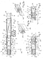
- These and other important features of the new machine and of the respective operating process, will be more apparent from the following description of a preferred embodiment and implementation thereof, illustrated purely by way of a non-limiting example, in the figures of the seven accompanying drawings, wherein:
-
Figure 1 is a schematic side view of the machine in the condition at the start of the cycle; -
Figures 2, 3 ,4 and 5 show, schematically and in side elevation, subsequent operating steps of the machine according toFigure 1 ; -
Figure 4a is a schematic top view and with parts in section of one of the moving lateral folding devices that act downstream of the tilting drum, shown in the active operating step; -
Figures 2a, 3a and5a illustrate a perspective view of the same number of subsequent steps of the cycle to form the packing, as illustrated in the respective machine steps inFigures 2, 3 and5 ; -
Figure 5b is an elevated view from the anterior end of the packing in the crosswise sealing step, as shown inFigures 5 and 5a ; -
Figures 6, 7 and 8 illustrate the packing in elevation from the anterior end in the last steps to close and fasten the lateral flaps; -
Figure 9 is a perspective view of the tilting drum shown from the inlet end of the product to be packed; -
Figure 10 illustrates the tilting drum viewed in elevation from the inlet end of the product and with some parts in section; -
Figures 11 ,12 and 13 illustrate the same number of details of the tilting drum sectioned respectively according to the lines XI-XI, XII-XII and XIII-XIII inFigure 10 ; -
Figure 14 illustrates the tilting drum in a side elevation and with the means to adjust the height of the axis of rotation thereof when the format of the product to be packed varies; -
Figure 15 schematically illustrates an epicyclic reduction gear, of the type used in the adjustment means according toFigures 12 and14 . - In the following description, embodiment and operation of the machine for packing groups of hand towel rolls is detailed, without however excluding use of the same machine to pack groups of other products, as will be better specified below.
- From
Figures 1 and9 , it can be seen that the machine comprises a feed unit 1, cyclically composed in which is a prismatic group with rectangular base of rolls P of paper, arranged in one or more layers placed on top of one another, and this feed unit is provided with anlower wall 101 which remains fixed when the format of the group of rolls P varies and is provided with anupper wall 201, which must instead be adjusted in the position in height when said format varies. The letter F inFigure 9 indicates a possible feed direction of the rolls of paper which, in the example herein (see alsoFigure 1 ), have their hollow core oriented longitudinally in the direction along which they are fed by the thrust crossbars 2 of feed conveyors, known and not illustrated. At the opposite end to the one involved by the crossbars 2, the feed unit 1 is closed by a verticalretaining wall 301, the position of which is adjusted when the format of products P varies. Located on one side of the feed unit 1 is apusher 3 connected to translation means 103 (Figure 9 ) positioned under theplate 101 which for this purpose has aslot 203 suitable for the projection that connects said translation means to thepusher 3 to pass through when it is activated to unload the group of rolls P from the feed unit 1 and to transfer it towards subsequent means, with a movement F1 in the direction orthogonal to the feed direction F of the group of rolls in said feed unit. The packing sheet 4 (Figure 1 ), which in the example in question is a heat-sealable plastic material, is positioned crosswise and with a suitable vertical arrangement on the opposite side of the feed unit 1 to the one engaged by theaforesaid pusher 3, and said sheet is retained by the upper flap and by the lower flap by pairs of parallel and motorizedbelts sheets 4 from a continuous film unwound from a reel, said unit being known and not illustrated in detail herein. On the same side of the feed unit 1 engaged by thepacking sheet 4, placed transversely to said sheet is afirst wrapping spindle 6, comprising a lowerhorizontal wall 106 and an upperhorizontal wall 206 coplanar respectively with thewalls walls folding spindle 6 that is opposite the one involved by thepacking sheet 4, in coplanar alignment, placed one over the other and motorized, are thehorizontal conveyors 8, 8' of thetilting drum 7, which can be controlled to rotate through 180° about itsaxis 107, which is horizontal and orthogonal to the longitudinal direction of saidconveyors 8, 8', located longitudinally between which, edgewise and with symmetrical arrangement, arelateral folding devices 9, 9' supported by said drum and suitable to operate actively with one or with the other of the ends thereof (see below). When the format of the product to be packed varies, means are provided to adjust the reciprocal distance between thelateral folding devices 9, 9' and other means to adjust the reciprocal distance of theconveyors 8, 8', while theentire tilting drum 7 is adjusted in the position in height, so that these conveyors are aligned with thewalls parts 1 and 6 mentioned previously. The means as described above operate in the following way. After a group of rolls P has been formed in the feed unit 1 (hereinafter the parallelepiped shaped group of rolls will simply be referred to with the term "product"), said product P is pushed by thepusher 3 towards the means downstream 6 and 7, while theconveyors 8, 8' of thedrum 7 are activated to run with the inner branches at the same speed and in the same feed direction as thepusher 3. The product P delivered from the feed unit 1 by thepusher 3, frontally touches thewrapping sheet 4, which is held in correct phase with a limited friction by theconveyor belts walls spindle 6 to then be positioned between theconveyors 8, 8' of thedrum 7. Specific guide means, not illustrated, support and correctly accompany the sheet released by thebelts spindle 6. Drawn by the product P and by theconveyors 8. 8', thewrapping sheet 4 is released from thebelts 5, 5' and when the product reaches saidconveyors 8, 8' of thedrum 7, thesheet 4 wraps the product P as shown inFigure 2 , in part on the upper face, on the anterior end in feed direction and on the lower face, substantially in the shape of a "U" rotated through ninety degrees and open in the direction of thepusher 3. On the side of thebelts wrapping sheet 4 is placed in relation to the formingspindle 6, so that in the step inFigure 2 said sheet projects from the lower face of the product P with aportion 104 of the correct length (see below). Simultaneously, as illustrated inFigure 2a , the sheet must also project with portions of adequate and identical width from the sides of the product P and in the step inFigure 2 thevertical folding flaps 204 of these projecting parts of the wrapping, cooperating with thefolding devices 9, 9' of thedrum 7, are folded on the lateral faces of the product P. The inner surfaces of thewalls walls folding spindle 6 that operate in contact with the product P and with thewrapping sheet 4, for construction and reciprocal vertical positioning, are such as to have a limited friction coefficient which is nonetheless adequate against said parts P and 4. Theconveyor belts 8, 8' of thedrum 7 are instead such as to have sufficient sliding friction against thewrapping sheet 4, so as to have a positive action thereon. - After insertion of the product and of the wrapping sheet between the conveyors of the
drum 7, as already mentioned with reference toFigure 2 , saidconveyors 8, 8' stop and thepusher 3 reverses its movement to return to the position it has at the start of the cycle as shown inFigure 3 , thedrum 7 is rotated through 180° about itsaxis 107, so that at the end of said rotation, through the action of specific guide and longitudinal tensioning means (see below), said wrappingportion 104 wraps the new anterior face in feed direction of the product P and again projects by the correct portion from the lower face of said product, as shown in the perspective view inFigure 3a . This lower and projectingportion 104 of the wrapping sheet cooperates with a fixedsuction cross bar 10 which maintains it suitably stretched, both during transition from the step inFigure 2 to the step inFigure 3 , and during the step illustrated below. - Downstream of and in coplanar alignment with the
conveyors 8, 8' of the tilting drum 7 (Figure 1 ) there is provided a pair ofhorizontal belt conveyors 11, 11', placed one over the other in parallel and motorized for control by means, not illustrated, that make them run with the inner branches away from thedrum 7 and at the same speed of movement as theconveyors 8, 8' of said tilting drum 7 (see below). In the space between theconveyors 11 and 11', laterally thereto and at the level of thedrum 7, there are provided longitudinally folding means 13 comprising apart 113 closer to the drum, guided and moving horizontally and a subsequent fixedposterior part 213. After the step inFigure 3 , as illustrated schematically inFigures 4 and 4a , the movinganterior part 113 of thelateral folding devices 13 is moved, by suitable means, towards the end of thelateral folding devices 9, 9' of thedrum 7, and positioned on the outside thereof with a tapered portion 113'. In the subsequent step theconveyors 8, 8' of thedrum 7 are operated to eject the product P with the wrapping sheet and simultaneously theconveyors 11, 11' are also activated to receive and remove without slip the pack ejected from thedrum 7. In this step a new product P with relative wrapping sheet is fed between theconveyors 8, 8' by thepusher 3, as already stated with reference toFigure 2 , so that the tiltingdrum 7 operates substantially without idle times, as is instead the case in the prior art. In this case, thetilting drum 7 rotates cyclically through 180° always in the same counter-clockwise direction looking at the accompanying drawings. In this same step, thesuction bar 10 maintains the projectingportion 104 of the wrapping sheet stretched longitudinally, which during transfer of the product between theconveyors 11, 11' is stretched under said product fed between said conveyors which stop (seeFigure 5 ) when the lower part of said product that is involved by the two overlapping parts of the wrapping sheet reaches the level of an intermediate and crosswise gap in thelower conveyor belt 11, defined by driving said belt around a plurality ofparallel rollers 14 and placed crosswise in said gap is a heat-sealing bar 15, which is raised and then lowered by suitable means to reciprocally seal the two overlapping parts of the wrapping sheet, using as counter-roller one of the rolls of paper forming the product P. During transfer from thedrum 7 to theconveyors 11, 11', the lateral flaps with vertical folding 204' of the wrapping sheet are folded on the lateral faces of the product P by thefolding device 13 and, as illustrated inFigures 5a and 5b , when the product reaches the level of thesealing bar 15, the lower lateral flaps withhorizontal folding 304 have been partly lifted by thefolding devices 16 positioned laterally to theconveyors 11, 11', as shown inFigure 1 , so that said flaps do not interfere with thesealing bar 15. In the next step, after thesealing bar 15 has been lowered and the seal performed has been suitably cooled, the packed product is once again moved forward by theconveyors 11, 11', while thelateral folding devices 16 andsubsequent folding devices 17 fold, on the lateral faces of the product, first saidflaps 304 as illustrated inFigure 6 and then the corresponding upper flaps 304' also with horizontal folding, which are placed reciprocally over each other and over the flaps withvertical folding 204, 204', as illustrated inFigure 7 . Finally,Figures 1 and8 show that the packed product is delivered from theconveyors 11, 11' and is picked up and moved away without slip by a lowerhorizontal conveyor 18 and by a pair of parallel andvertical conveyors 19, all motorized at the correct speed and aheating source 20 operates between said vertical conveyors to perform heat sealing and reciprocal fastening of said lateral and overlapping flaps of the packing sheet, with a technique known in the art which will not be explained in depth herein and which includes adjusting means to adjust all the means operating downstream of the tiltingdrum 7 to operate on products of different format. -
Figures 9 ,10 and11 show that the tiltingdrum 7 has side panels formed by a pair oftoothed wheels 207, 207' of large diameter and identical, supported rotatingly by the external uprights of aU-shaped supporting structure 21, better explained below and which are motorized in rigid phase by connection by means oftoothed belts 22, withtensioning devices 23, to the toothed pulleys of thesame diameter 24 of aparallel synchronization shaft 25 which with the ends is supported rotatingly by saidframe 21 and which with a suitable positive drive transmission 26 (Figures 10, 11 ) is connected to amotor 27, also fastened to theframe 21 and preferably of the type with electronic control of speeds and phase, e.g. a brushless motor. Fastened on the inner faces of saidside panels 207, 207' with symmetrical arrangement in relation to the axis ofrotation 107 of thedrum 7, are pairs ofrectilinear precision guides 28, 28', sliding on which are recirculatingball guides 29; 29' integral with the ends of theflat frame 108, 108' which supports the pulleys and belts placed side by side with and parallel to each other forming theconveyors 8, 8' of thedrum 7 and means are provided (see below) to vary, in a self-centering manner, the distance between saidconveyors 8, 8' when the format of the product to be packed varies. The belts of theconveyors 8, 8' are also driven around toothed pulleys keyed ontoshafts 208, 208' external to saidflat frames 108, 108', supported rotatingly thereby and said shafts support, keyed onto a same end, respectiveidentical toothed pulleys 30, 30' involved respectively by the inner toothing and by the outer toothing of abelt 31 with double toothing which kinematically connects said pulleys to apulley 32 positioned coaxially on the inner face of theadjacent side panel 207 of the drum and keyed onto the shaft of anelectric motor 33 with electronic control of speed and phase, flanged with the body thereof onto the outer face of the upright of thestructure 21 that rotatingly supports saidside panel 207. At the level of thetoothed pulleys 30, 30', thebelt 31 is made to follow a sinuous path to be driven aroundother toothed pulleys side panel 207. By varying, in a self-centering manner, the distance between theconveyors 8, 8' of thedrum 7 with the means specified below, it appears evident that the double branches of thebelt 31 driven around thepulleys 30, 30' modify their length in opposite ways, as while one double branch is shortened, the other double branch is lengthened by a same distance, always maintaining thebelt 31 correctly stretched. - With reference to
Figures 10 ,11 and12 , it can be seen that thelateral folding devices 9, 9', which operate inside the tiltingdrum 7, are provided on the outer face with pairs ofrods tubes 209, 209', flanged with the other end on the inner face of theside panels 207, 207' of thedrum 7. These tubes are provided at the level of the fastening flange, with outer projections 309 (Figure 12 ) which rotatingly support the intermediate part of corresponding pairs of right andleft screws 36, 36', parallel to theguides 28, 28' and the ends of which cooperate withcasings 37, 37' provided with corresponding screw nuts, not shown, and integral with theframes 108, 108' of theconveyors 8, 8'. By means of positivekinematic connections 38, 38', e.g. of the type with pinions and with chains positioned longitudinally on theframes 108, 108', the screw nuts of thescrews 36 are connected in phase with those of the screws 36', while at the level of the side panel 207' of thedrum 7, the screw nuts of the screws 36' are connected to each other by means of a pair ofpositive drives 39, 39', which comprise conical couplings andgearboxes 139, 139', which are integral with theframes 108, 108' and are each provided with an input axis parallel to theaxis 107 of thedrum 7, facing the side panel 207', and keyed onto which are identicaltoothed pulleys 40, 40' driven around which respectively with its outer toothing and with its inner toothing is abelt 41 with double toothing, which derives motion from a controltoothed pulley 42 positioned on theaxis 107 of thedrum 7. By means ofidle pulleys 43 supported by the side panel 207' of saiddrum 7, thetoothed belt 41 is obliged to take a sinuous path, in which it involves said toothed pulleys 40, 40', with double branches, all so that when the self-centering variation of the reciprocal distance between theframes 108, 108' of theconveyors 8, 8' occurs, said double branches of thebelt 41 modify their length in a simultaneous and opposite way, maintaining the tension of saidtoothed belt 41 unchanged. - From
Figure 12 it appears evident that when thepulley 42 is rotated in one direction or the other, depending on whether the distance between theconveyors 8, 8' of thedrum 7 is to be increased or decreased, through thetoothed belt 41 rotation is transmitted to thepulleys 40, 40' and through thekinematic mechanisms 39, 39' it is transmitted to the screw nuts of thecasings 37 and also to those of the casings 37' to which they are connected with thedrives 38, 38' and with rotation of said screw nuts on the fixed screws 36, 36', theframes 108, 108' move reciprocally away from or towards each other by the required distance and with self-centering movement. -
Figures 10 to 15 show that thetoothed pulley 42 is keyed onto the output shaft of anepicyclic reduction gear 44 which with itsbody 144 is mounted rotatingly on thehub 121 of theframe 21 which rotatingly supports with bearings the side panel 207', by means ofbushings 45 or other suitable means. Keyed onto the input shaft of thereduction gear 44 is atoothed pulley 46 which through atoothed belt 47 is connected to a correspondingtoothed pulley 48 keyed onto theshaft 25, which synchronizes rotation of the twoside panels 207, 207' of the drum 7 (Figure 14 ). - On the side of the
input pulley 46 there is provided a pinion orother means 49 which throughchains 249 is connected to a corresponding pinion 149 (Figure 14 ) keyed onto anadjustment shaft 50 mounted rotatingly on theframe 21 and which can be made to rotate with a manual control or with a servocontrol. Adjustment of the distance between theconveyors 8, 8' of thedrum 7 is implemented through theshaft 50 and usually with the machine stopped. With rotation of theshaft 50 and of thepinion 49, as thepulley 46 remains still (Figure 15 ), thebody 144 of thereduction gear 44 rotates and the output shaft with thepulley 42 rotates proportionally to the input rotation imparted to thepinion 49, determining the required adjustment of the reciprocal distance of theconveyors 8, 8'. - To maintain the distance between these
conveyors 8, 8' unchanged when thedrum 7 rotates cyclically through 180°, as in this step thepinion 49 and the body of thereduction gear 44 are stopped, said rotation of the drum is imparted with thebelt 47 and thepulley 46, to the primary shaft of thereduction gear 44, so as to obtain the required effects. - From
Figure 14 it appears evident that by varying the reciprocal distance between theconveyors 8, 8' of the tilting drum, the distance between the lower one of said conveyors varies in relation to thelower component 106 of thefolding spindle 6 and of theconveyor 11 downstream, and therefore it is necessary to make a corresponding adjustment of the position in height of the axis ofrotation 107 of saiddrum 7. FromFigures 9 ,10 ,11 ,13 and14 it can be seen that theframe 21, which rotatingly supports thedrum 7, is provided with at least one pair ofvertical slides 51, with recirculating balls, positioned on planes orthogonal to each other and sliding on correspondingguides 151 supported by theuprights 152 of asolid bed structure 52 provided with eye-bolts 53 for handling of the entire apparatus with the tilting device. With a lower cross-member thereof, theframe 21 is connected to thebed 52 by means of a pair of verticalmechanical jacks 54 with screw-screw nut, synchronized by adrive transmission 55 with screw-helical gear, which by means of apositive drive 56, e.g. with pinions and chain (Figures 10 ,13 ,14 ) is connected kinematically to theshaft 50 with itsdrive 150 for manual operation or with suitable means and with aregister 250 that helps the operator in the adjustment to be made. By acting on theshaft 50 to vary the relative distance of theconveyors 8, 8', thejacks 54 are simultaneously activated to modify the position in height of the axis of thedrum 7 as specified above. - From
Figures 13 and14 it appears that thedrive transmission 55 that synchronizes thejacks 54 is connected with apositive drive transmission 59 to asynchronization shaft 60 mounted rotatingly on a movingframe 21 and which throughconical couplings 61 rotates a pair ofvertical shafts 62 supported rotatingly bybushings 63 also integral with theframe 21, so as to move vertically therewith. Theshafts 62 are provided with identicalupper threads 162 which cooperate withscrew nuts 64 integral with lateral supportingbrackets 65 of theupper plate 206 of thefirst folding spindle 6, so that when the distance between theconveyors 8, 8' of thedrum 7 varies, the distance of theplate 206 from the lower fixedplate 106 is also automatically varied. Between thedrive 59 and the shaft 60 a disengaging device, not shown, can be provided, which can be operated to release said shaft and prepare it for fine and selective rotation, with means not indicated and suitable for the purpose. - In
Figures 11 and13 , the numeral 57 indicates supports integral with thebed 52, which support the first means 11, 11' located downstream of the tiltingdrum 7 and which support under said drum, one of the curved guides 58 that correctly accompany theportion 104 of the packing sheet during cyclic rotation of thetilting device 7, as stated with reference toFigures 2 and 3 . - It is understood that the description refers to a preferred embodiment of the invention, to which numerous variants and modifications can be made, above all in relation to the type of product to be packed. If the machine is intended for the treatment of products which, due to their nature and/or the arrangement of their components, cannot be compressed to any great degree, the
conveyors 8, 8' of thedrum 7 can use belts that are suitably elastic-yielding or that can be mounted on specific springing means. If need be, theplates first folding spindle 6, can be replaced by suitable idle or motorized conveyors. - This modification falls within the scope of the invention, as claimed hereunder. In the claims, the references indicated in brackets are purely indicative and do not limit the scope of protection of said claims.
Claims (22)
- Method for packing groups of products or products (P) of prismatic shape with rectangular or square base, which from a feed or grouping unit are then moved towards a first folding spindle (6) so as to be delivered therefrom wrapped substantially in the shape of a "U" rotated through 90° and open at the back, by a packing sheet (4) which is previously placed in front of said spindle with vertical positioning, wherein the product along with the packing sheet delivered from said spindle (6) are picked up directly and fed in phase between the parallel and horizontal motorized conveyors (8, 8') of a tilting drum (7), characterized in that: positioned inside said tilting drum folding devices (9, 9') are arranged, placed longitudinally, edgewise and parallel with each other; said folding devices (9, 9') laterally guide the product with the packing sheet and fold on the lateral faces of said product the first flaps of said packing sheet with vertical folding (204), projecting laterally and anterior in feed direction, while said products are advanced along said tilting drum by said conveyors (8, 8'); and that it is possible to operate on products (P) of different format, keeping as fixed reference the ideal horizontal plane on which said products run in the packing step, there being provided steps to vary, in a self-centering manner, the distance between the conveyors (8, 8') of the tilting drum (7) and to adjust the position in height of the axis of rotation (107) of said tilting drum, with lowering or lifting of this position respectively in the case of decrease or in the case of increase of the format.
- Method as claimed in claim 1, characterized in that: after folding of said first flaps said conveyors (8, 8') are stopped, said tilting drum (7) is controlled to rotate cyclically through 180°, always in the same direction and always loaded with a partially packed product, and after each rotation of said tilting drum (7) about its axis (107) orthogonal to the feed direction of the product, the conveyors (8, 8') of said tilting drum (7) are reactivated to eject the product with the packing sheet towards means that complete folding and fastening of the flaps of said packing sheet (4); and in the same step a new product with relative packing sheet unloaded directly from said first folding spindle (6) is fed between the conveyors (8, 8') of said tilting drum (7).
- Machine for packing groups of products (P), in particular for implementation of the method as claimed in any one of the previous claims, comprising:- a feed unit (1) in which a group of products (P) or a product is introduced, which is then fed horizontally in a pre-established direction (F1) for the packing cycle;- a first folding spindle (6) placed transversely to said feed unit (1) and aligned therewith according to said direction (F1);- means (5, 105) for cyclically positioning a packing sheet (4) with vertical arrangement between said feed unit (1) and said spindle (6), the dimensions and placing of said sheet being correlated to the format of the product to be packed;- a motorized pusher (3) which in correct phase and with alternate movements pushes the product to be delivered from said feed unit (1) and fed through said folding spindle (6) drawing therewith said packing sheet which in correct phase is released by the relative feed means (5, 105') and which wraps the product in the shape of a "U" rotated through 90° and open at the back;- a tilting drum (7) which with a pair of motorized conveyors (8, 8') receives the product with the packing sheet delivered from said folding spindle (6) and pushed by said pusher (3), means being provided to cyclically rotate said tilting drum (7) by 180° always in the same direction around a rotation axis (107);- downstream of said tilting drum, means (11, 11'-20) which receive the product and the packing sheet cyclically unloaded from the tilting drum (7) and which complete folding of the flaps of the packing sheet and fasten them;characterized in that said tilting drum (7) includes folding devices (9, 9') arranged longitudinally and parallel to each other between said conveyors, said folding devices laterally guiding the product with the packing sheet and fold on the lateral faces of said product the first flaps of said packing sheet with vertical folding (204), projecting laterally and anterior in feed direction; said conveyors (8, 8') and said tilting drum (7) being arranged and controlled such that, at the end of each rotation of said tilting drum (7) said conveyors (8, 8') are reactivated to eject the previously fed product and the packing sheet and to introduce a new product with the packing sheet coming from said first folding spindle (6) into said tilting drum (7); that the distance between said conveyors (8, 8') is adjustable in a self-centering manner; and that the position in height of the axis of rotation (107) of said tilting drum (7) is adjustable by lowering or lifting said axis in the case of decrease or increase of the products format, respectively, such as to operate on products (P) of different formats, keeping as fixed reference the ideal horizontal plane on which said products run in the packing step.
- Machine as claimed in claim 3, characterized in that if it is intended to pack products that cannot be compressed to any great degree, the conveyors (8, 8') of the tilting drum can use suitably elastic-yielding belts and/or mounted on specific springing means.
- Machine as claimed in claim 3, wherein the feed unit (1), in which the group of products (P) placed in one or more layers is formed, comprises a lower wall (101) which remains fixed, and at least an upper wall (201) which is adjusted in the position in height when the format of said group of products varies, which when composed of rolls of paper, are preferably placed with the axis of their core on the horizontal or on the vertical and parallel to the packing sheet (4) in its original vertical position.
- Machine as claimed in claim 3, wherein the lower plate (101) of the feed unit (1) in which the group of products (P) to be packed is arranged, is provided with a longitudinal slot (203) passed through by the projection that connects the pusher (3) to the relative translation means (103) positioned under said plate and parallel to said slot.
- Machine as claimed in claim 4, wherein the first folding spindle (6) comprises a lower wall (106) fixed and coplanar with the lower plate or conveyor (101) of the feed unit (1) and comprises an upper wall or conveyor (206) coplanar with the upper wall (201) of said feed unit and which is connected by means of an adjusting device to adjust the position in height when the format of products to be packed varies.
- Machine as claimed in claim 3, wherein the means that in correct phase position a packing sheet (4) between the feed unit (1) and the first folding spindle (6) comprise pairs of parallel and motorized belts (5, 105) and other means to take said packing sheet (4) from a continuous strip unwound from a reel and comprise guide means to support and maintain said packing sheet stretched when in correct phase this is released by said belts and is drawn by the product (P) through said first folding spindle.
- Machine as claimed in claim 3, wherein the side panels of the tilting drum (7) are formed of toothed wheels (207, 207'), identical and of large diameter, supported rotatingly by external uprights of a U-shaped supporting structure (21), and which are motorized in rigid phase by connection by means of toothed belts (22) to the toothed pulleys of the same diameter (24) of a synchronization shaft (25) which with the ends is supported rotatingly by said frame (21), together with a relative electric drive motor (27), preferably of the type with electronic control of speed and phase, e.g. a brushless motor.
- Machine as claimed in claim 3, wherein fastened on the inner faces of the side panels (207, 207') of the tilting drum (7), with symmetrical arrangement in relation to the axis of rotation (107) of said tilting drum, are pairs of rectilinear precision guides (28, 28'), sliding on which are precision slides (29, 29') integral with the ends of the flat frame (108, 108') which supports the pulleys and belts placed side by side with and parallel to each other of the conveyors (8, 8') of said tilting drum (7).
- Machine as claimed in claim 10, wherein the the conveyors (8, 8') of the tilting drum (7) include belts which are driven around pulleys keyed onto shafts (208, 208') external to said flat frames (108, 108'), supported rotatingly thereby and said shafts support, keyed onto a same end, respective identical toothed pulleys (30, 30') one involved by the inner toothing and the other by the outer toothing of a belt (31) with double toothing, which kinematically connects said pulleys to a pulley (32) positioned coaxially on the inner face of the adjacent side panel (207) of the tilting drum and keyed onto the shaft of an electric motor (33) with electronic control of speed and phase, flanged with the body thereof on the outer face of the upright of the structure (21) that rotatingly supports said side panel (207), it being provided that said belt (31) is made to follow a sinuous path to be driven around other pulleys (34, 35, 35') supported idle by the inner face of said side panel (207) so that said belt is driven with double branches around said pulleys (30, 30'), all so that when self-centering variation of the distance between parallel conveyors (8, 8') of the tilting drum (7) takes place, these double branches of the belt (31) modify their length in an opposite way, always maintaining said belt correctly stretched.
- Machine as claimed in claim 10, wherein supported rotatingly parallel to said guides (28, 28') with the intermediate part thereof by said side panels (207, 207') of the tilting drum (7), are corresponding pairs of screws with right left thread (36, 36'), which with the ends thereof cooperate with casings (37, 37') with corresponding screw nuts and integral with the end corner areas of the frames (108, 108') of the conveyors (8, 8'), it being provided that by means of positive kinematic connections (38, 38'), positioned longitudinally and externally to said frames (108, 108'), the screw nuts of one end (36) are connected in phase with those (36') of the other end and it being provided that at the level of a side panel (207) of the tilting drum (7), the end screw nuts of the corresponding pair of screws (36) are connected to each other by means of a pair of positive drives (39, 39'), which comprise gearboxes (139, 139') integral with the frames (108, 108') and each provided with an input axis parallel to the axis of rotation (107) of the tilting drum (7) and facing the adjacent side panel (207'), keyed onto which are corresponding toothed pulleys of the same diameter (40, 40'), driven around which with its opposite toothing is a belt with double toothing (41) which derives motion from a control toothed pulley (42) rotating on the axis of rotation of the tilting drum and connected to specific adjustment means, and finally it being provided that by means of idle pulleys (43) supported by said side panel (207') of the tilting drum, said belt (41) is made to follow a sinuous path in which it involves said principal pulleys (40, 40') with double branches, all so that when the self-centering variation of the reciprocal distance between the frames (108, 108') of the conveyors (8, 8') takes place, said double branches of the belt (41) modify their length in a simultaneous and opposite way, maintaining the tension of said belt (41) unchanged.
- Machine as claimed in claim 12, wherein the toothed pulley (42) that controls adjustment of the reciprocal distance of the conveyors (8, 8') of the tilting drum (7), is keyed onto the output shaft of an epicyclic reduction gear (44) which with its body (144) is mounted rotatingly and coaxially on the hub (121) of the frame (21) which rotatingly supports with bearings the adjacent side panel (207'), it being provided that keyed onto the input shaft of said reduction gear (44) is a toothed pulley (46) which through a toothed belt (47) is connected to a corresponding toothed pulley (48) keyed onto the shaft (25) which synchronizes rotation of the two side panels (207, 207') of the tilting drum (7) and there being provided on the side of said input pulley (46) a pinion (49) keyed axially to the body of the reduction gear and connected through a chain (249) to a corresponding pinion (149) keyed onto an adjustment shaft (50) rotating on said frame (21) and which can be made to rotate with a manual control or with a servocontrol to adjust the distance between the conveyors (8, 8') of the tilting drum (7).
- Machine as claimed in one or more claims 3 to 13, wherein the moving frame (21) which rotatingly supports the tilting drum (7) is mounted sliding vertically with groups of precision guides and slides (51, 151), on the uprights (152) of a bed structure (52) which is connected to a cross-member above of said moving frame (21) by means of a pair of vertical mechanical jacks (54) with screw-screw nut, synchronized by a drive transmission (55), which by means of another positive drive transmission (56) is connected kinematically to said adjustment shaft (50) by acting on which it is possible to adjust the distance between the conveyors (8, 8') of the tilting drum and simultaneously modify the position in height of said tilting drum (7) to maintain the lower one of said conveyors (8, 8') in coplanar alignment with the lower plate (106) of the first folding spindle (6).
- Machine as claimed in claim 14, wherein the drive transmission (55) that synchronizes said jacks (54) is connected by means of a further positive drive transmission (59) to a synchronization shaft (60) mounted rotatingly on the moving frame (21) and which through conical gear couplings (61) rotates a pair of vertical shafts (62) supported rotatingly by bushings (63) also integral with said frame (21), said shafts being provided superiorly with identical threads (162) which cooperate with screw nuts (64) integral with lateral supporting brackets (65) of the upper plate (206) of said first folding spindle (6), all so that when the distance between the conveyors (8, 8') of the tilting drum (7) varies, the distance of the upper plate (206) of said spindle (6) in relation to the respective lower fixed plate (106) is also automatically varied, suitably for the format of product to be packed.
- Machine as claimed in claim 15, wherein between said drive transmission (59) and the synchronization shaft (60) is provided an engaging and disengaging device, which can be operated to release said shaft and prepare it for fine and selective rotation, to better adapt the dimensional characteristics of the first folding spindle (6) to the characteristics of the product (P) to be packed.
- Machine as claimed in one or more of claims 3to 16, wherein the lateral folding devices (9, 9') which operate inside the tilting drum (7), are provided on the outer face with pairs of rods (109, 109') that slide guided and manually adjustable inside tubes (209, 209'), fastened with the other end on the inner face of the side panels (207, 207') of said tilting drum (7).
- Machine as claimed in one or more of claims 3 to 17, characterized in that on the unloading end of the tilting drum (7), parallel and under the lower conveyor of said tilting drum, there is provided a suction bar which maintains the last inferior flap (104) of the packing sheet longitudinally stretched, so that it is correctly placed on the portion of said sheet already wound around the product, while the assembly is unloaded from the tilting drum.
- Machine as claimed in one or more of claims 3 to 18, wherein downstream of and in coplanar alignment with the conveyors (8, 8') of the tilting drum (7) there is provided a pair of horizontal belt conveyors (11, 11'), adjustable according to format, placed one over the other in parallel and motorized so as to run with the inner branches thereof away from said tilting drum and at the same speed as the conveyors (8, 8') of this component, there being provided in the space between said conveyors, laterally thereto and at the level of said tilting drum (7), with longitudinal arrangement, folding means (13) comprising a portion (113) closer to the tilting drum, guided and moving horizontally under the action of specific actuators and which comprise a fixed posterior portion (213), there being provided means so that, before a product is unloaded from the tilting drum (7), said moving part (113) of the folding devices downstream (13) are moved towards the end of the lateral folding devices (9, 9') of the tilting drum (7) to be positioned as a bridge and on the outside thereof, to facilitate subsequent feed of the product with the wrapping sheet during the step to unload it from said tilting drum (7).
- Machine as claimed in claim 19, wherein the lower one (11) of said belt conveyors (11, 11') is provided in the intermediate part with a crosswise gap defined by driving said belt around a plurality of parallel rollers (14) and placed crosswise in said gap is a heat-sealing bar (15) which is lifted and then lowered by suitable means to reciprocally seal the two overlapping parts of the heat-sealable wrapping sheet that wraps the product in a tube, using as counter-roller one of the rolls of paper forming said product, there being provided for this purpose means that temporarily stop said conveyors (11, 11') when the packed product transported reaches the correct position in relation to said heat-sealing bar.
- Machine as claimed in claim 20, wherein on the sides of said belt conveyors (11, 11') there are provided static folding devices (16, 17) which make use of the feed movement of the product in the packing step to fold in succession on the lateral flaps with vertical folding, already folded previously, first the lower lateral flap with horizontal folding (304) and then the upper and opposite lateral flap (304').
- Machine as claimed in claim 21, wherein downstream of said pair of belt conveyors (11, 11') there is provided a horizontal belt conveyor (18) aligned and coplanar with the lower one (11) of the conveyors upstream and which runs in the same direction and at the same speed, and laterally to said conveyor (18) there is provided a pair of parallel conveyors with vertical axis (19) between which heating sources (20) operate to perform heat-sealing of the lateral and overlapping flaps of the packing of the product which is retained and made to advance without slip between this group of three conveyors synchronized with one another.
Applications Claiming Priority (2)
| Application Number | Priority Date | Filing Date | Title |
|---|---|---|---|
| IT000630A ITBO20050630A1 (en) | 2005-10-20 | 2005-10-20 | METHOD AND MACHINE FOR PACKAGING OF GROUPS OF PRODUCTS ORDERED ON ONE OR MORE LAYERS |
| PCT/IT2006/000746 WO2007046126A1 (en) | 2005-10-20 | 2006-10-18 | Method and machine for packing groups of products arranged in one or more layers |
Publications (2)
| Publication Number | Publication Date |
|---|---|
| EP1937557A1 EP1937557A1 (en) | 2008-07-02 |
| EP1937557B1 true EP1937557B1 (en) | 2010-01-20 |
Family
ID=37715952
Family Applications (1)
| Application Number | Title | Priority Date | Filing Date |
|---|---|---|---|
| EP06810034A Not-in-force EP1937557B1 (en) | 2005-10-20 | 2006-10-18 | Method and machine for packing groups of products arranged in one or more layers |
Country Status (11)
| Country | Link |
|---|---|
| US (1) | US7797913B2 (en) |
| EP (1) | EP1937557B1 (en) |
| JP (1) | JP2009512601A (en) |
| CN (1) | CN101312882B (en) |
| AT (1) | ATE455703T1 (en) |
| BR (1) | BRPI0617733B1 (en) |
| DE (1) | DE602006011928D1 (en) |
| ES (1) | ES2337185T3 (en) |
| IT (1) | ITBO20050630A1 (en) |
| RU (1) | RU2411166C2 (en) |
| WO (1) | WO2007046126A1 (en) |
Cited By (1)
| Publication number | Priority date | Publication date | Assignee | Title |
|---|---|---|---|---|
| IT202200011771A1 (en) | 2022-06-03 | 2023-12-03 | Valmet Tissue Converting S P A | PAPER PRODUCT LAUNCHING MACHINE |
Families Citing this family (32)
| Publication number | Priority date | Publication date | Assignee | Title |
|---|---|---|---|---|
| ITFI20070029A1 (en) * | 2007-02-07 | 2008-08-08 | Kpl Packaging Spa | MACHINE AND METHOD FOR PACKAGING MANUFACTURED GROUPS WITH DOUBLE WELDING SYSTEM. |
| US7818950B1 (en) | 2007-05-30 | 2010-10-26 | Walgreen Co. | Method of loading a multi-dose blister card using a transfer fixture |
| US7866476B2 (en) | 2007-05-30 | 2011-01-11 | Walgreen Co. | Multi-dose blister card pillbook |
| US8251219B1 (en) | 2007-10-22 | 2012-08-28 | Walgreen Co. | Package for medicine |
| DE102008052633A1 (en) * | 2008-10-22 | 2010-04-29 | Khs Ag | Method and device for producing a packaging unit |
| GB0911999D0 (en) * | 2009-07-10 | 2009-08-19 | Oakbridge Invest Ltd | Packaging method and apparatus |
| DE102010015865A1 (en) * | 2010-03-09 | 2011-09-15 | Krones Ag | Apparatus and method for packaging articles |
| IT1399584B1 (en) * | 2010-03-15 | 2013-04-26 | Bernacchi | METHOD FOR THE PACKAGING OF GROUPS OF ITEMS, AND PACKAGING MACHINE THAT ACTIVATES THIS METHOD |
| US9205994B2 (en) | 2011-09-19 | 2015-12-08 | The Procter & Gamble Company | Methods for transferring items |
| ITFI20110220A1 (en) * | 2011-10-10 | 2013-04-11 | Kpl Packaging Spa | "PACKAGING MACHINE FOR PACKAGING PAPER ROLLS" |
| CN102673819A (en) * | 2012-05-15 | 2012-09-19 | 金红叶纸业集团有限公司 | Packaging machine and end face packaging device thereof |
| JP6187805B2 (en) * | 2013-04-23 | 2017-08-30 | 株式会社パックマン | Packaging equipment |
| CN103612863B (en) * | 2013-10-29 | 2016-06-29 | 广东众和化塑有限公司 | A kind of woven bag parcel edge-folding mechanism |
| US10196162B2 (en) * | 2014-05-14 | 2019-02-05 | Tissue Machinery Company S.P.A. | Apparatus for packaging batches of products packed in cartons or in wrapping film |
| ITUB20152063A1 (en) * | 2015-07-10 | 2017-01-10 | Cps Company S R L | Wrapping machine for single or grouped and / or stacked products, in packages of thermoplastic material obtained from a film unwound from a reel and relative working process |
| KR102117795B1 (en) * | 2016-07-05 | 2020-06-03 | 봅스트 맥스 에스에이 | A module for turning over folding packages and a folding package production line comprising such a module |
| IT201700060353A1 (en) * | 2017-06-01 | 2018-12-01 | Cps Company S R L | Process and apparatus for packaging products with film of thermoplastic material unwound from a reel |
| IT201700077504A1 (en) * | 2017-07-10 | 2019-01-10 | Leon Ribi | Plant for assembling PVC bottles or other similar containers in bundles by applying tape-like bonds, also called straps |
| US20190047731A1 (en) * | 2017-08-12 | 2019-02-14 | Kretchman Holdings, LLC | Utensil Wrapping Apparatus |
| CN109132059B (en) * | 2018-09-14 | 2020-06-23 | 江苏丁嘉材料科技有限公司 | Stock form is folded and packaging machine |
| CN109987278B (en) * | 2019-04-24 | 2023-04-25 | 广东石油化工学院 | Cored wire coil packaging device and packaging method thereof |
| CN110282174B (en) * | 2019-08-12 | 2024-03-22 | 西华大学 | Candy wrapping paper bi-polar kink device |
| US11535411B2 (en) * | 2019-12-19 | 2022-12-27 | The Procter & Gamble Company | Folding apparatus |
| US11780619B2 (en) * | 2020-01-30 | 2023-10-10 | H.G. Weber And Company, Inc. | Systems for packaging stacks of bags |
| CN112124710B (en) * | 2020-10-21 | 2022-04-12 | 深圳市优德油脂工程技术有限公司 | Automatic intelligent packaging line for massive edible oil |
| CN112849515B (en) * | 2020-12-31 | 2022-04-26 | 安徽省盛鑫绝缘材料有限公司 | Slot wedge material loading processing integrated device |
| JP7680247B2 (en) * | 2021-04-02 | 2025-05-20 | 日本製紙株式会社 | packaging equipment |
| IT202100018176A1 (en) | 2021-07-09 | 2023-01-09 | Koerber Tissue S P A | A SYSTEM FOR PACKAGING PRODUCTS IN TISSUE PAPER USING SHEETS OF WRAP |
| IT202200019440A1 (en) * | 2022-09-22 | 2024-03-22 | Valmet Tissue Converting S P A | PACKAGING MACHINE WITH SEALING MATERIAL DISPENSING DEVICE |
| SE547177C2 (en) * | 2023-03-31 | 2025-05-06 | Valmet Oy | Folding apparatus, system for covering a pulp bale with wrapping material and method for folding a sheet of wrapping material around a pulp bale |
| CN116281373B (en) * | 2023-05-18 | 2023-08-29 | 连云港市智欣捷机械有限公司 | Non-woven fabric product folding device and application method thereof |
| CN118164268B (en) * | 2024-04-16 | 2024-08-09 | 泰安嘉旭工贸有限公司 | Automatic stacking equipment for carton packaging |
Family Cites Families (26)
| Publication number | Priority date | Publication date | Assignee | Title |
|---|---|---|---|---|
| US3681893A (en) * | 1970-06-22 | 1972-08-08 | Emhart Corp | Packing machine for folding blanks around article groups fed continuously therethrough |
| JPS5247643Y2 (en) * | 1971-11-29 | 1977-10-28 | ||
| US4083163A (en) * | 1976-10-22 | 1978-04-11 | Ganz Brothers, Inc. | Package forming machine |
| IT1169175B (en) * | 1983-02-23 | 1987-05-27 | Gambetti Mario Baumer | MACHINE FOR PACKING CONTINUOUSLY MOVING ITEMS WITH A TAPE OF HEAT-SHRINKABLE MATERIAL |
| IT1200208B (en) * | 1986-09-24 | 1989-01-05 | Gd Spa | DEVICE FOR FEEDING STAGNOLA CUTS IN A CIGARETTE PACKING MACHINE |
| DE3701273A1 (en) * | 1987-01-17 | 1988-07-28 | Focke & Co | METHOD AND DEVICE FOR PACKING PAPER HANDKERCHIEFS |
| JPH0454883Y2 (en) * | 1987-03-13 | 1992-12-24 | ||
| DD280302A1 (en) * | 1989-03-01 | 1990-07-04 | Rationalisierungsmittel Betrie | DEVICE FOR AUTOMATIC PACKAGING OF OBJECTS |
| IT1245996B (en) * | 1991-05-24 | 1994-11-07 | Wrapmatic Spa | METHOD FOR THE WRAPPING OF STACKS OF PAPER AND EQUIPMENT THAT REALIZES IT. |
| IT1246012B (en) * | 1991-06-21 | 1994-11-07 | Gd Spa | WRAPPING METHOD AND DEVICE FOR THE PRODUCTION OF TUBULAR PRODUCT WRAPS. |
| IT1263438B (en) * | 1993-06-18 | 1996-08-05 | Baumer Srl | METHOD AND EQUIPMENT FOR THE TRANSPORT OF THE WINDING BAND IN THE WRAPPING STAGES OF THE ITEMS IN THE MACHINES PACKING MACHINES OF ITEMS WITH WRAPS OF WRAPPING MATERIAL. |
| IT1280002B1 (en) * | 1995-08-01 | 1997-12-23 | Gd Spa | METHOD AND MACHINE FOR THE REALIZATION OF PRODUCT WRAPS |
| IT1285575B1 (en) * | 1996-03-01 | 1998-06-18 | Gd Spa | METHOD AND UNIT FOR THE BENDING OF LONG Wrapping BLANK PRE-WEAKENED BENDING LINES. |
| DE19860018A1 (en) | 1997-12-30 | 1999-07-08 | Tmc Spa | Production line for automatically packaging confectionery items in three sections at different levels |
| RU2230691C2 (en) * | 1998-12-07 | 2004-06-20 | Фераг Аг | Method and device for stacked printed items wrapping |
| IT1304441B1 (en) * | 1998-12-22 | 2001-03-19 | Baumer Srl | METHOD FOR PACKAGING OBJECTS THROUGH LEAF OF THERMORETRACTIVE MATERIALS AND RELATED PACKING MACHINE. |
| IT1320919B1 (en) * | 2000-03-14 | 2003-12-10 | Resta Srl | MATTRESS PACKAGING MACHINE IN A SHEET CARRIED OUT CONTINUOUSLY ON A COIL. |
| ITBO20000685A1 (en) * | 2000-11-23 | 2002-05-23 | Gianluigi Gamberini | TOWING DEVICE FOR MACHINES FOR PACKAGING ARTICLES IN ROLLS AND SIMILAR |
| ITTO20010075A1 (en) * | 2001-01-26 | 2002-07-26 | Innopack S R L | METHOD AND WRAPPING MACHINE OF SHEETS. |
| ITBO20010733A1 (en) * | 2001-11-30 | 2003-05-30 | Innopack S R L | APPARATUS, AND RELATED METHOD, FOR THE WRAPPING OF PAPER RIMS |
| ITBO20030093A1 (en) * | 2003-02-25 | 2004-08-26 | Azionario Costruzioni Macchine Auto Matiche A C Ma | METHOD AND DEVICE FOR WRAPPING GROUPS OF PRODUCTS |
| ITBO20030436A1 (en) * | 2003-07-22 | 2005-01-23 | Aetna Group Spa | EQUIPMENT FOR PRODUCT GROUPS. |
| US6935091B2 (en) * | 2003-11-06 | 2005-08-30 | Techmatic S.R.L. | Method and apparatus for wrapping articles with a packaging sheet |
| ITBO20040253A1 (en) * | 2004-04-23 | 2004-07-23 | Aetna Group Spa | MACHINE FOR THE PACKAGING OF GROUPS OF PRODUCTS BY TUBULAR ELEMENTS OF ELASTIC FILM |
| DE102004046576A1 (en) * | 2004-09-23 | 2006-03-30 | Focke & Co.(Gmbh & Co. Kg) | Device for wrapping groups of packages |
| ITBO20060168A1 (en) * | 2006-03-10 | 2006-06-09 | Gd Spa | WRAPPING WHEEL. |
-
2005
- 2005-10-20 IT IT000630A patent/ITBO20050630A1/en unknown
-
2006
- 2006-10-18 DE DE602006011928T patent/DE602006011928D1/en active Active
- 2006-10-18 RU RU2008119815/21A patent/RU2411166C2/en not_active IP Right Cessation
- 2006-10-18 EP EP06810034A patent/EP1937557B1/en not_active Not-in-force
- 2006-10-18 AT AT06810034T patent/ATE455703T1/en not_active IP Right Cessation
- 2006-10-18 WO PCT/IT2006/000746 patent/WO2007046126A1/en not_active Ceased
- 2006-10-18 CN CN2006800435238A patent/CN101312882B/en not_active Expired - Fee Related
- 2006-10-18 US US12/083,802 patent/US7797913B2/en not_active Expired - Fee Related
- 2006-10-18 BR BRPI0617733-6A patent/BRPI0617733B1/en not_active IP Right Cessation
- 2006-10-18 ES ES06810034T patent/ES2337185T3/en active Active
- 2006-10-18 JP JP2008536209A patent/JP2009512601A/en active Pending
Cited By (1)
| Publication number | Priority date | Publication date | Assignee | Title |
|---|---|---|---|---|
| IT202200011771A1 (en) | 2022-06-03 | 2023-12-03 | Valmet Tissue Converting S P A | PAPER PRODUCT LAUNCHING MACHINE |
Also Published As
| Publication number | Publication date |
|---|---|
| US20090139185A1 (en) | 2009-06-04 |
| WO2007046126A1 (en) | 2007-04-26 |
| RU2411166C2 (en) | 2011-02-10 |
| DE602006011928D1 (en) | 2010-03-11 |
| JP2009512601A (en) | 2009-03-26 |
| CN101312882A (en) | 2008-11-26 |
| ATE455703T1 (en) | 2010-02-15 |
| BRPI0617733A2 (en) | 2011-08-02 |
| US7797913B2 (en) | 2010-09-21 |
| RU2008119815A (en) | 2009-11-27 |
| EP1937557A1 (en) | 2008-07-02 |
| CN101312882B (en) | 2011-03-23 |
| BRPI0617733B1 (en) | 2018-08-07 |
| ES2337185T3 (en) | 2010-04-21 |
| ITBO20050630A1 (en) | 2007-04-21 |
Similar Documents
| Publication | Publication Date | Title |
|---|---|---|
| US7797913B2 (en) | Method and machine for packing groups of products arranged in one or more layers | |
| CN101309834B (en) | Method and machine for packaging groups of products ordered in one or more layers | |
| AU2012322361B2 (en) | Packaging machine for packing rolls of paper and the like | |
| CN107848644B (en) | Packaging machine and method for packaging individual or groups of products in packages | |
| JP3837436B2 (en) | Multi-pack packaging equipment | |
| EP0413371B1 (en) | Automatic apparatus for folding sheets | |
| US20150251785A1 (en) | Packaging Machine For Packaging Rolls Wound Around Winding Cores | |
| US20020170271A1 (en) | Horizontal cartoner system and method for the use thereof | |
| US20160229567A1 (en) | Apparatus for manufacturing packaging units | |
| JP5222318B2 (en) | Transport device | |
| CN117262384B (en) | Cloth roll plastic packaging equipment and method thereof | |
| CN116788585B (en) | Gypsum board packaging equipment | |
| CN211996251U (en) | Bearing tapered roller packaging system | |
| US7607277B2 (en) | Work piece wrapping apparatus | |
| CN115416910A (en) | Adopt reel formula to go up paper books baling equipment | |
| CN115339683B (en) | A kind of moon cake packaging production equipment and packaging method using the equipment | |
| JP3993945B2 (en) | Wrapping material transport device for upper packaging machine | |
| CN218751715U (en) | Quantitative mask packaging and conveying device | |
| EP0670278B1 (en) | Form, fill and seal wrapping machine | |
| CN115973505B (en) | Full-automatic wrapping machine | |
| JP2002255105A (en) | Filling and packaging machine | |
| CN116534343A (en) | Candy box packaging device with heat seal function | |
| CN111252304A (en) | Full-automatic packing assembly line of cloth | |
| HK1252989B (en) | Wrapping machine for wrapping single or grouped products in packs and related method | |
| ITBO960364A1 (en) | PROCESS AND MACHINE FOR FAST PACKAGING OF ENTR PRODUCTS OR BAGS MADE FROM THERMOPLASTIC FILM |
Legal Events
| Date | Code | Title | Description |
|---|---|---|---|
| PUAI | Public reference made under article 153(3) epc to a published international application that has entered the european phase |
Free format text: ORIGINAL CODE: 0009012 |
|
| 17P | Request for examination filed |
Effective date: 20080407 |
|
| AK | Designated contracting states |
Kind code of ref document: A1 Designated state(s): AT BE BG CH CY CZ DE DK EE ES FI FR GB GR HU IE IS IT LI LT LU LV MC NL PL PT RO SE SI SK TR |
|
| 17Q | First examination report despatched |
Effective date: 20081120 |
|
| GRAP | Despatch of communication of intention to grant a patent |
Free format text: ORIGINAL CODE: EPIDOSNIGR1 |
|
| GRAS | Grant fee paid |
Free format text: ORIGINAL CODE: EPIDOSNIGR3 |
|
| GRAA | (expected) grant |
Free format text: ORIGINAL CODE: 0009210 |
|
| AK | Designated contracting states |
Kind code of ref document: B1 Designated state(s): AT BE BG CH CY CZ DE DK EE ES FI FR GB GR HU IE IS IT LI LT LU LV MC NL PL PT RO SE SI SK TR |
|
| REG | Reference to a national code |
Ref country code: GB Ref legal event code: FG4D |
|
| REG | Reference to a national code |
Ref country code: CH Ref legal event code: EP |
|
| REG | Reference to a national code |
Ref country code: IE Ref legal event code: FG4D |
|
| REF | Corresponds to: |
Ref document number: 602006011928 Country of ref document: DE Date of ref document: 20100311 Kind code of ref document: P |
|
| REG | Reference to a national code |
Ref country code: ES Ref legal event code: FG2A Ref document number: 2337185 Country of ref document: ES Kind code of ref document: T3 |
|
| REG | Reference to a national code |
Ref country code: NL Ref legal event code: VDEP Effective date: 20100120 |
|
| LTIE | Lt: invalidation of european patent or patent extension |
Effective date: 20100120 |
|
| PG25 | Lapsed in a contracting state [announced via postgrant information from national office to epo] |
Ref country code: AT Free format text: LAPSE BECAUSE OF FAILURE TO SUBMIT A TRANSLATION OF THE DESCRIPTION OR TO PAY THE FEE WITHIN THE PRESCRIBED TIME-LIMIT Effective date: 20100120 |
|
| PG25 | Lapsed in a contracting state [announced via postgrant information from national office to epo] |
Ref country code: IS Free format text: LAPSE BECAUSE OF FAILURE TO SUBMIT A TRANSLATION OF THE DESCRIPTION OR TO PAY THE FEE WITHIN THE PRESCRIBED TIME-LIMIT Effective date: 20100520 Ref country code: PT Free format text: LAPSE BECAUSE OF FAILURE TO SUBMIT A TRANSLATION OF THE DESCRIPTION OR TO PAY THE FEE WITHIN THE PRESCRIBED TIME-LIMIT Effective date: 20100520 Ref country code: NL Free format text: LAPSE BECAUSE OF FAILURE TO SUBMIT A TRANSLATION OF THE DESCRIPTION OR TO PAY THE FEE WITHIN THE PRESCRIBED TIME-LIMIT Effective date: 20100120 Ref country code: LT Free format text: LAPSE BECAUSE OF FAILURE TO SUBMIT A TRANSLATION OF THE DESCRIPTION OR TO PAY THE FEE WITHIN THE PRESCRIBED TIME-LIMIT Effective date: 20100120 |
|
| PG25 | Lapsed in a contracting state [announced via postgrant information from national office to epo] |
Ref country code: SI Free format text: LAPSE BECAUSE OF FAILURE TO SUBMIT A TRANSLATION OF THE DESCRIPTION OR TO PAY THE FEE WITHIN THE PRESCRIBED TIME-LIMIT Effective date: 20100120 Ref country code: FI Free format text: LAPSE BECAUSE OF FAILURE TO SUBMIT A TRANSLATION OF THE DESCRIPTION OR TO PAY THE FEE WITHIN THE PRESCRIBED TIME-LIMIT Effective date: 20100120 Ref country code: LV Free format text: LAPSE BECAUSE OF FAILURE TO SUBMIT A TRANSLATION OF THE DESCRIPTION OR TO PAY THE FEE WITHIN THE PRESCRIBED TIME-LIMIT Effective date: 20100120 Ref country code: PL Free format text: LAPSE BECAUSE OF FAILURE TO SUBMIT A TRANSLATION OF THE DESCRIPTION OR TO PAY THE FEE WITHIN THE PRESCRIBED TIME-LIMIT Effective date: 20100120 |
|
| PG25 | Lapsed in a contracting state [announced via postgrant information from national office to epo] |
Ref country code: SE Free format text: LAPSE BECAUSE OF FAILURE TO SUBMIT A TRANSLATION OF THE DESCRIPTION OR TO PAY THE FEE WITHIN THE PRESCRIBED TIME-LIMIT Effective date: 20100120 Ref country code: BE Free format text: LAPSE BECAUSE OF FAILURE TO SUBMIT A TRANSLATION OF THE DESCRIPTION OR TO PAY THE FEE WITHIN THE PRESCRIBED TIME-LIMIT Effective date: 20100120 Ref country code: CY Free format text: LAPSE BECAUSE OF FAILURE TO SUBMIT A TRANSLATION OF THE DESCRIPTION OR TO PAY THE FEE WITHIN THE PRESCRIBED TIME-LIMIT Effective date: 20100120 Ref country code: EE Free format text: LAPSE BECAUSE OF FAILURE TO SUBMIT A TRANSLATION OF THE DESCRIPTION OR TO PAY THE FEE WITHIN THE PRESCRIBED TIME-LIMIT Effective date: 20100120 Ref country code: GR Free format text: LAPSE BECAUSE OF FAILURE TO SUBMIT A TRANSLATION OF THE DESCRIPTION OR TO PAY THE FEE WITHIN THE PRESCRIBED TIME-LIMIT Effective date: 20100421 Ref country code: RO Free format text: LAPSE BECAUSE OF FAILURE TO SUBMIT A TRANSLATION OF THE DESCRIPTION OR TO PAY THE FEE WITHIN THE PRESCRIBED TIME-LIMIT Effective date: 20100120 |
|
| PLBE | No opposition filed within time limit |
Free format text: ORIGINAL CODE: 0009261 |
|
| STAA | Information on the status of an ep patent application or granted ep patent |
Free format text: STATUS: NO OPPOSITION FILED WITHIN TIME LIMIT |
|
| PG25 | Lapsed in a contracting state [announced via postgrant information from national office to epo] |
Ref country code: BG Free format text: LAPSE BECAUSE OF FAILURE TO SUBMIT A TRANSLATION OF THE DESCRIPTION OR TO PAY THE FEE WITHIN THE PRESCRIBED TIME-LIMIT Effective date: 20100420 Ref country code: SK Free format text: LAPSE BECAUSE OF FAILURE TO SUBMIT A TRANSLATION OF THE DESCRIPTION OR TO PAY THE FEE WITHIN THE PRESCRIBED TIME-LIMIT Effective date: 20100120 Ref country code: CZ Free format text: LAPSE BECAUSE OF FAILURE TO SUBMIT A TRANSLATION OF THE DESCRIPTION OR TO PAY THE FEE WITHIN THE PRESCRIBED TIME-LIMIT Effective date: 20100120 |
|
| 26N | No opposition filed |
Effective date: 20101021 |
|
| PG25 | Lapsed in a contracting state [announced via postgrant information from national office to epo] |
Ref country code: DK Free format text: LAPSE BECAUSE OF FAILURE TO SUBMIT A TRANSLATION OF THE DESCRIPTION OR TO PAY THE FEE WITHIN THE PRESCRIBED TIME-LIMIT Effective date: 20100120 |
|
| PG25 | Lapsed in a contracting state [announced via postgrant information from national office to epo] |
Ref country code: IT Free format text: LAPSE BECAUSE OF FAILURE TO SUBMIT A TRANSLATION OF THE DESCRIPTION OR TO PAY THE FEE WITHIN THE PRESCRIBED TIME-LIMIT Effective date: 20100120 |
|
| PG25 | Lapsed in a contracting state [announced via postgrant information from national office to epo] |
Ref country code: MC Free format text: LAPSE BECAUSE OF NON-PAYMENT OF DUE FEES Effective date: 20101031 |
|
| REG | Reference to a national code |
Ref country code: CH Ref legal event code: PL |
|
| PG25 | Lapsed in a contracting state [announced via postgrant information from national office to epo] |
Ref country code: CH Free format text: LAPSE BECAUSE OF NON-PAYMENT OF DUE FEES Effective date: 20101031 Ref country code: LI Free format text: LAPSE BECAUSE OF NON-PAYMENT OF DUE FEES Effective date: 20101031 |
|
| PG25 | Lapsed in a contracting state [announced via postgrant information from national office to epo] |
Ref country code: IE Free format text: LAPSE BECAUSE OF NON-PAYMENT OF DUE FEES Effective date: 20101018 |
|
| PG25 | Lapsed in a contracting state [announced via postgrant information from national office to epo] |
Ref country code: LU Free format text: LAPSE BECAUSE OF NON-PAYMENT OF DUE FEES Effective date: 20101018 Ref country code: HU Free format text: LAPSE BECAUSE OF FAILURE TO SUBMIT A TRANSLATION OF THE DESCRIPTION OR TO PAY THE FEE WITHIN THE PRESCRIBED TIME-LIMIT Effective date: 20100721 |
|
| PG25 | Lapsed in a contracting state [announced via postgrant information from national office to epo] |
Ref country code: TR Free format text: LAPSE BECAUSE OF FAILURE TO SUBMIT A TRANSLATION OF THE DESCRIPTION OR TO PAY THE FEE WITHIN THE PRESCRIBED TIME-LIMIT Effective date: 20100120 |
|
| REG | Reference to a national code |
Ref country code: FR Ref legal event code: PLFP Year of fee payment: 10 |
|
| REG | Reference to a national code |
Ref country code: FR Ref legal event code: PLFP Year of fee payment: 11 |
|
| REG | Reference to a national code |
Ref country code: FR Ref legal event code: PLFP Year of fee payment: 12 |
|
| REG | Reference to a national code |
Ref country code: FR Ref legal event code: PLFP Year of fee payment: 13 |
|
| PGFP | Annual fee paid to national office [announced via postgrant information from national office to epo] |
Ref country code: FR Payment date: 20181025 Year of fee payment: 13 Ref country code: GB Payment date: 20181031 Year of fee payment: 13 Ref country code: ES Payment date: 20181127 Year of fee payment: 13 |
|
| PGFP | Annual fee paid to national office [announced via postgrant information from national office to epo] |
Ref country code: DE Payment date: 20181228 Year of fee payment: 13 |
|
| REG | Reference to a national code |
Ref country code: DE Ref legal event code: R119 Ref document number: 602006011928 Country of ref document: DE |
|
| PG25 | Lapsed in a contracting state [announced via postgrant information from national office to epo] |
Ref country code: DE Free format text: LAPSE BECAUSE OF NON-PAYMENT OF DUE FEES Effective date: 20200501 |
|
| GBPC | Gb: european patent ceased through non-payment of renewal fee |
Effective date: 20191018 |
|
| PG25 | Lapsed in a contracting state [announced via postgrant information from national office to epo] |
Ref country code: FR Free format text: LAPSE BECAUSE OF NON-PAYMENT OF DUE FEES Effective date: 20191031 Ref country code: GB Free format text: LAPSE BECAUSE OF NON-PAYMENT OF DUE FEES Effective date: 20191018 |
|
| REG | Reference to a national code |
Ref country code: ES Ref legal event code: FD2A Effective date: 20210302 |
|
| PG25 | Lapsed in a contracting state [announced via postgrant information from national office to epo] |
Ref country code: ES Free format text: LAPSE BECAUSE OF NON-PAYMENT OF DUE FEES Effective date: 20191019 |