EP1937442B1 - Portable fastening tool - Google Patents
Portable fastening tool Download PDFInfo
- Publication number
- EP1937442B1 EP1937442B1 EP06797659.7A EP06797659A EP1937442B1 EP 1937442 B1 EP1937442 B1 EP 1937442B1 EP 06797659 A EP06797659 A EP 06797659A EP 1937442 B1 EP1937442 B1 EP 1937442B1
- Authority
- EP
- European Patent Office
- Prior art keywords
- housing
- fastening tool
- handle portion
- magazine
- battery pack
- Prior art date
- Legal status (The legal status is an assumption and is not a legal conclusion. Google has not performed a legal analysis and makes no representation as to the accuracy of the status listed.)
- Active
Links
- 238000004080 punching Methods 0.000 claims description 13
- 239000002023 wood Substances 0.000 description 3
- 239000011347 resin Substances 0.000 description 2
- 229920005989 resin Polymers 0.000 description 2
- 230000005540 biological transmission Effects 0.000 description 1
- 238000002485 combustion reaction Methods 0.000 description 1
- 239000002360 explosive Substances 0.000 description 1
- 239000000463 material Substances 0.000 description 1
- 238000004804 winding Methods 0.000 description 1
Images


Classifications
-
- B—PERFORMING OPERATIONS; TRANSPORTING
- B25—HAND TOOLS; PORTABLE POWER-DRIVEN TOOLS; MANIPULATORS
- B25C—HAND-HELD NAILING OR STAPLING TOOLS; MANUALLY OPERATED PORTABLE STAPLING TOOLS
- B25C1/00—Hand-held nailing tools; Nail feeding devices
- B25C1/06—Hand-held nailing tools; Nail feeding devices operated by electric power
Definitions
- the present invention relates to a portable fastening tool for punching nails with a driving force established by a battery.
- a portable fastening tool of this kind is constituted by: a housing having a handle portion extending generally in a side elevation of T-shape from a generally cylindrical trunk portion; an ejection unit attached to the lower portion of the housing; a magazine attached to the ejection unit; a motor housed in the housing; a battery for driving the motor; a flywheel rotatably supported by the housing and rotationally driven by the motor; a follower shaft rotatably supported by the housing and selectively rotated by the kinetic energy of the flywheel; and a plunger linearly moved in the housing by the rotation of the follower shaft thereby to drive the nails fed into the ejection unit.
- the nails connected in a step shape are housed in the magazine.
- the magazine is so attached to the housing that it is inclined in a side view at the same angle as the connection angle of nails (as referred to JP-A-6-278051 and JP-A-2002-127039 , for example).
- the handle portion is formed at such an angle as close to the horizontal direction, so that the trunk portion of the housing may be easily pushed onto the punching side. Moreover, easy use of the portable fastening tool in a narrow place is also considered by keeping the trailing end portion of the handle portion of the housing (or the free end portion on the opposite side of the trunk portion) lower than the trunk portion.
- the magazine for housing a number of nails connected in the step shape is attached obliquely in a side view to the housing.
- the handle portion has to be likewise inclined. If the handle portion is excessively inclined, however, there arise a problem to make it hard to push the trunk portion onto the punching side. If the trailing end portion of the handle portion of the housing is higher than the end portion on the trunk side, the portable fastening tool becomes tall as a whole thereby to deteriorate the operability and workability of the machine in a narrow place.
- a portable fastening tool with the features included in the preamble of claim 1 is known from US 2002/0104869 A1 .
- the magazine is mounted obliquely, as viewed from the ejection port, with respect to the handle portion so as to avoid the interference with the battery. Even if the magazine is attached obliquely in the top plan view to the handle portion of the housing, the battery or a heavy component can be arranged at the low position so that the portable fastening tool can be well balanced in its weight and less damaged in its operation.
- the right and left sides of the electric fastening tool will means the right and left sides of the case, in which the electric fastening tool is seen from the operator in case the operator grips the handle portion of the electric fastening tool.
- the top plan view is taken in Fig.1 from above the electric fastening tool, and the bottom view is taken in Fig. 1 from below the electric fastening tool.
- numeral 2 designates a housing made of a resin and acting as an exterior member.
- This housing 2 is constituted to include a generally cylindrical trunk portion 2A, and a handle portion 2B jointed generally in the shape of letter T, as viewed in a side view, to the trunk portion 2A.
- a battery pack 3 for housing the not-shown battery as the power source.
- a trigger switch 4 is disposed at the handle portion 2B of the housing 2 and near the trunk portion 2A.
- an ejection unit 17 to which a flat box-shaped magazine 5 is attached obliquely, in a side view, to the trunk portion 2A.
- this magazine 5 as shown in Fig. 5 , there are horizon, the position of the handle portion of the housing can be held nearly horizontal while avoiding the magazine, and the portable fastening tool can be easily pushed to the punching side while gripping the handle portion, so that the nailing operations can be stabilized.
- the magazine is so arranged that its portion overlaps either the portion of the handle portion of the housing or the battery in the side view.
- the height of the trailing end portion (or the end portion on the opposite side of the trunk portion) of the handle portion i.e., the height from the leading end punching portion of the trunk portion
- the electric fastening tool 1 can be held small to make the electric fastening tool 1 so compact that it can be conveniently used in the narrow place, so that it can nail even a narrow place highly efficiently.
- the magazine is mounted obliquely, as viewed from the ejection port, with respect to the handle portion so as to avoid the interference with the battery. Even if the magazine is attached obliquely in the top plan view to the handle portion of the housing, the battery or a heavy component can be arranged at the low position so that the portable fastening tool can be well balanced in its weight and less damaged in its operation.
- Fig. 1 is a lefthand side elevation of an electric fastening tool (or a portable fastening tool) according to the invention
- Fig. 2 is a bottom view of the same electric fastening tool
- Fig. 3 is a broken righthand side elevation showing the internal constitution of the same electric fastening tool
- Fig. 4 is a side elevation showing the nailing operation using the same electric fastening tool
- Fig. 5 is a side elevation of nails connected in a step shape.
- the right and left sides of the electric fastening tool will means the right and left sides of the case, in which the electric fastening tool is seen from the operator in case the operator grips the handle portion of the electric fastening tool.
- the top plan view is taken in Fig. 1 from above the electric fastening tool
- the bottom view is taken in Fig. 1 from below the electric fastening tool.
- numeral 2 designates a housing made of a resin and acting as an exterior member.
- This housing 2 is constituted to include a generally cylindrical trunk portion 2A, and a handle portion 2B jointed generally in the shape of letter T, as viewed in a side view, to the trunk portion 2A.
- a battery pack 3 for housing the not-shown battery as the power source.
- a trigger switch 4 is disposed at the handle portion 2B of the housing 2 and near the trunk portion 2A.
- a flat box-shaped magazine 5 is attached obliquely, in a side view, to the trunk portion 2A.
- this magazine 5 as shown in Fig. 5 , there are housed a number of nails 6, which are connected in a step shape. More specifically, the magazine 5 is attached, at its one end, to the ejection unit 17 (as located at the lower end portion of Fig. 1 ) disposed at the leading end of the trunk portion 2A of the housing 2 and, at its other end, to the trailing end portion of the handle portion 2B of the housing 2 and near the battery pack 3.
- the ejection unit 17 as located at the lower end portion of Fig. 1
- the magazine 5 is inclined obliquely upward from the ejection unit 17 disposed at the leading end of the trunk portion 2A of the housing 2 toward the trailing end portion of the handle portion 2B.
- the magazine 5 forms a triangular shape, in a side view, together with the trunk portion 2A and the handle portion 2B of the housing 2.
- the electric fastening tool (or the portable fastening tool) 1 is characterized in that the magazine 5 is attached obliquely in the bottom view (as taken from the side of the ejection port 17a of the ejection unit 17) to the handle portion 2B of the housing 2, as shown in Fig. 2 . More specifically, the magazine 5 is attached so obliquely in a bottom view to the handle portion 2B of the housing 2 that it is turned in its entirety by a predetermined angle ⁇ leftward (or upward of Fig. 2 ) on the ejection unit 17 disposed at the leading end of the trunk portion 2A of the housing 2.
- the magazine 5 is attached obliquely to the handle portion 2B by turning it leftward of the bottom view on the ejection unit 17 disposed at the leading end of the trunk portion 2A of the housing 2.
- the magazine 5 may also be attached obliquely to the handle portion 2B by turning it rightward (or downward of Fig. 2 ).
- the magazine 5 is attached obliquely of the side view to the trunk portion 2A of the housing 2 and obliquely of the bottom view to the handle portion 2B of the housing 2.
- the magazine 5 is arranged to have its portion overlapping the battery pack 3 disposed at the trailing end portion of the handle portion 2B of the housing 2, as shown in Fig. 1 , and is attached so obliquely to the handle portion 2B that its overlapping portion may have no interference (or overlap) with the battery pack 3, as shown in Fig. 2 . Therefore, the inclination angle ⁇ (as referred to Fig.
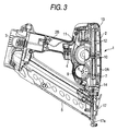
- the internal constitution of the housing 2 is described with reference to Fig. 3 .
- a motor 7 acting as a drive source from which an output shaft (or motor shaft) 8 extends in the direction of the center of rotation thereof (i.e., in the direction normal to the sheet of Fig. 3 ).
- a drive gear 9 is fixed on the end portion of the output shaft 8.
- This clutch mechanism is constituted to include a clutch spring wound on the flywheel 11 and the follower shaft, an electromagnetic solenoid acting as an actuator for winding the clutch spring on the outer circumference of the follower shaft, and a drive circuit for driving the electromagnetic solenoid.
- a plunger 12 meshing with the pinion 10 that it can move reciprocally and linearly upward and downward of Fig. 3 along a guide rail 13.
- a blade or a punching portion 14 for punching out the nails 6.
- the plunger 12 is biased in such a direction (upward of Fig. 3 ) by the not-shown return spring as to return to the initial position.
- the trigger switch 4 When the trigger switch 4 is pulled and turned ON, the motor 7 is energized by the battery housed in the battery pack 3.
- the rotations of the output shaft 8 of the motor 7 are transmitted from the drive gear 9 to the flywheel 11 so that the flywheel 11 is rotationally driven to store the kinetic energy.
- the clutch mechanism is in OFF state, and the flywheel 11 and the driven shaft are disconnected.
- the flywheel 11 is freely (idly) rotating with respect to the follower shaft, so that the transmission of the power (or the kinetic energy) from the flywheel 11 to the follower shaft is blocked.
- the electromagnetic solenoid is energized by the not-shown drive circuit so that it is driven.
- the clutch mechanism is turned ON to connect the flywheel 11 and the follower shaft so that the kinetic energy of the flywheel 11 is transmitted to rotate the follower shaft.
- the driven shaft is thus rotationally driven, the pinion 10 fixed on the driven shaft rotates together, thereby to push the meshing plunger 12 in the punching direction (downward of Fig. 3 ) against the biasing force of the not-shown return spring.
- the blade 14 attached to the leading end of the plunger 12 is also pushed in the same direction to impinge at its leading end against the nail 6 housed in the magazine 5.
- the nail 6 is pushed from the ejection port 17a of the ejection unit 17 so that it is driven into a material such as wood W, as shown in Fig. 4 .
- the energization of the electromagnetic solenoid is interrupted and turned OFF, and the clutch mechanism is also turned OFF to disconnect the flywheel 11 and the follower shaft. Then, the follower shaft can rotate freely with respect to the flywheel 11 so that the plunger 12 and the blade 14 attached to the plunger 12 are moved upward of Fig. 3 their initial positions by the biasing force of the not-shown return spring.
- the nails 6 shown in Fig. 5 can be continuously driven into the wood W shown in Fig. 4 .
- the electric fastening tool 1 even if the magazine 5 having the nails 6 housed in the step shape, as shown in Fig. 5 is attached at an inclination with respect to the horizontal direction, the magazine 5 can be so attached while avoiding the handle portion 2B of the housing 2 as to hold the handle portion 2B at an angle near a horizontal direction. Moreover, the electric fastening tool 1 can be entirely shortened and can be easily pushed while gripping the handle portion 2B, so that it can punch the nails 6 stably.
- the magazine 5 is so arranged that its portion overlaps either the trailing end portion of the handle portion 2B of the housing 2 or the battery pack 3 in the side view.
- the height of the trailing end portion of the handle portion 2B i.e., the height from the leading end punching portion of the trunk portion 2A
- the electric fastening tool 1 can be made so compact that it can be conveniently used in the narrow place, as shown in Fig. 4 , so that it can nail even a narrow place highly efficiently.
- the magazine 5 is mounted obliquely in a top plan view, as shown in Fig. 2 , with respect to the handle portion 2B so as to avoid the interference with the battery pack 3.
- the battery can be easily attached to or detached from the battery pack 3 so that it can be replaced easily and promptly.
- the battery or a heavy component can be arranged at the low position so that the electric fastening tool (or the portable fastening tool) 1 can be well balanced in its weight and less damaged in its operation.
- the embodiment of the invention has been described on the electric fastening tool as one example of the portable fastening tool.
- the invention can also be naturally applied to another portable fastening tool such as a gas fastening tool, in which a gas is burned by sparking it with a battery so that the nail is driven by the explosive force (or the combustion energy) of the gas.
Description
- The present invention relates to a portable fastening tool for punching nails with a driving force established by a battery.
- A portable fastening tool of this kind is constituted by: a housing having a handle portion extending generally in a side elevation of T-shape from a generally cylindrical trunk portion; an ejection unit attached to the lower portion of the housing; a magazine attached to the ejection unit; a motor housed in the housing; a battery for driving the motor; a flywheel rotatably supported by the housing and rotationally driven by the motor; a follower shaft rotatably supported by the housing and selectively rotated by the kinetic energy of the flywheel; and a plunger linearly moved in the housing by the rotation of the follower shaft thereby to drive the nails fed into the ejection unit.
- Of these portable fastening tools, there is a type, in which the nails connected in a step shape are housed in the magazine. In the portable fastening tool of this type, the magazine is so attached to the housing that it is inclined in a side view at the same angle as the connection angle of nails (as referred to
JP-A-6-278051 JP-A-2002-127039 - In the portable fastening tool of the related art, on the other hand, the handle portion is formed at such an angle as close to the horizontal direction, so that the trunk portion of the housing may be easily pushed onto the punching side. Moreover, easy use of the portable fastening tool in a narrow place is also considered by keeping the trailing end portion of the handle portion of the housing (or the free end portion on the opposite side of the trunk portion) lower than the trunk portion.
- In the related-art portable fastening tool, the magazine for housing a number of nails connected in the step shape is attached obliquely in a side view to the housing. In order to avoid the interference with the magazine, the handle portion has to be likewise inclined. If the handle portion is excessively inclined, however, there arise a problem to make it hard to push the trunk portion onto the punching side. If the trailing end portion of the handle portion of the housing is higher than the end portion on the trunk side, the portable fastening tool becomes tall as a whole thereby to deteriorate the operability and workability of the machine in a narrow place.
- A portable fastening tool with the features included in the preamble of claim 1 is known from
US 2002/0104869 A1 . - It is an object of the invention to provide a compact portable fastening tool which can be easily pushed at its handle portion onto a punching site and in which interference of the battery pack by the magazine is avoided.
- This object is achieved by the portable fastening tool defined in claim 1.
- According to the invention, the magazine is mounted obliquely, as viewed from the ejection port, with respect to the handle portion so as to avoid the interference with the battery. Even if the magazine is attached obliquely in the top plan view to the handle portion of the housing, the battery or a heavy component can be arranged at the low position so that the portable fastening tool can be well balanced in its weight and less damaged in its operation.
-
-
Fig. 1 is a left-hand side elevation of an electric fastening tool according to an embodiment; -
Fig. 2 is a bottom view of the electric fastening tool according to the embodiment; -
Fig. 3 is a broken right-hand side elevation showing the internal configuration of the electric fastening tool according to the embodiment; -
Fig. 4 is a side elevation showing the nailing operation using the electric fastening tool according to the embodiment; and -
Fig. 5 is a side elevation of nails connected in a step shape. - An embodiment of the invention is described in connection with an electric fastening tool as one mode of embodiment of a portable fastening tool with reference to the accompanying drawings.
- In the following, the right and left sides of the electric fastening tool will means the right and left sides of the case, in which the electric fastening tool is seen from the operator in case the operator grips the handle portion of the electric fastening tool. Moreover, the top plan view is taken in
Fig.1 from above the electric fastening tool, and the bottom view is taken inFig. 1 from below the electric fastening tool. - In an electric fastening tool 1 according to this embodiment,
numeral 2 designates a housing made of a resin and acting as an exterior member. Thishousing 2 is constituted to include a generallycylindrical trunk portion 2A, and ahandle portion 2B jointed generally in the shape of letter T, as viewed in a side view, to thetrunk portion 2A. At the trailing end portion of thehandle portion 2B (or at the free end portion on the side opposed to thetrunk portion 2A) of thehousing 2, moreover, there is disposed abattery pack 3 for housing the not-shown battery as the power source. Moreover, atrigger switch 4 is disposed at thehandle portion 2B of thehousing 2 and near thetrunk portion 2A. - At the lower end of the
housing 2, as shown inFig. 1 , there is disposed anejection unit 17, to which a flat box-shaped magazine 5 is attached obliquely, in a side view, to thetrunk portion 2A. In thismagazine 5, as shown inFig. 5 , there are horizon, the position of the handle portion of the housing can be held nearly horizontal while avoiding the magazine, and the portable fastening tool can be easily pushed to the punching side while gripping the handle portion, so that the nailing operations can be stabilized. - According to another aspect of the invention, the magazine is so arranged that its portion overlaps either the portion of the handle portion of the housing or the battery in the side view. As a result, the height of the trailing end portion (or the end portion on the opposite side of the trunk portion) of the handle portion (i.e., the height from the leading end punching portion of the trunk portion) can be held small to make the electric fastening tool 1 so compact that it can be conveniently used in the narrow place, so that it can nail even a narrow place highly efficiently.
- According to another aspect of the invention, the magazine is mounted obliquely, as viewed from the ejection port, with respect to the handle portion so as to avoid the interference with the battery. Even if the magazine is attached obliquely in the top plan view to the handle portion of the housing, the battery or a heavy component can be arranged at the low position so that the portable fastening tool can be well balanced in its weight and less damaged in its operation.
-
-
Fig. 1 is a lefthand side elevation of an electric fastening tool according to an embodiment; -
Fig. 2 is a bottom view of the electric fastening tool according to the embodiment; -
Fig. 3 is a broken righthand side elevation showing the internal configuration of the electric fastening tool according to the embodiment; -
Fig. 4 is a side elevation showing the nailing operation using the electric fastening tool according to the embodiment; and -
Fig. 5 is a side elevation of nails connected in a step shape. - An embodiment of the invention is described in connection with an electric fastening tool as one mode of embodiment of a portable fastening tool with reference to the accompanying drawings.
-
Fig. 1 is a lefthand side elevation of an electric fastening tool (or a portable fastening tool) according to the invention;Fig. 2 is a bottom view of the same electric fastening tool;Fig. 3 is a broken righthand side elevation showing the internal constitution of the same electric fastening tool;Fig. 4 is a side elevation showing the nailing operation using the same electric fastening tool; andFig. 5 is a side elevation of nails connected in a step shape. In the following, the right and left sides of the electric fastening tool will means the right and left sides of the case, in which the electric fastening tool is seen from the operator in case the operator grips the handle portion of the electric fastening tool. Moreover, the top plan view is taken inFig. 1 from above the electric fastening tool, and the bottom view is taken inFig. 1 from below the electric fastening tool. - In an electric fastening tool 1 according to this embodiment,
numeral 2 designates a housing made of a resin and acting as an exterior member. Thishousing 2 is constituted to include a generallycylindrical trunk portion 2A, and ahandle portion 2B jointed generally in the shape of letter T, as viewed in a side view, to thetrunk portion 2A. At the trailing end portion of thehandle portion 2B (or at the free end portion on the side opposed to thetrunk portion 2A) of thehousing 2, moreover, there is disposed abattery pack 3 for housing the not-shown battery as the power source. Moreover, atrigger switch 4 is disposed at thehandle portion 2B of thehousing 2 and near thetrunk portion 2A. - At the lower end of the
housing 2, as shown inFig. 1 , there is disposed anejection unit 17, to which a flat box-shaped magazine 5 is attached obliquely, in a side view, to thetrunk portion 2A. In thismagazine 5, as shown inFig. 5 , there are housed a number ofnails 6, which are connected in a step shape. More specifically, themagazine 5 is attached, at its one end, to the ejection unit 17 (as located at the lower end portion ofFig. 1 ) disposed at the leading end of thetrunk portion 2A of thehousing 2 and, at its other end, to the trailing end portion of thehandle portion 2B of thehousing 2 and near thebattery pack 3. In the state shown inFig. 1 , themagazine 5 is inclined obliquely upward from theejection unit 17 disposed at the leading end of thetrunk portion 2A of thehousing 2 toward the trailing end portion of thehandle portion 2B. As a result, themagazine 5 forms a triangular shape, in a side view, together with thetrunk portion 2A and thehandle portion 2B of thehousing 2. - Thus, the electric fastening tool (or the portable fastening tool) 1 according to this embodiment is characterized in that the
magazine 5 is attached obliquely in the bottom view (as taken from the side of theejection port 17a of the ejection unit 17) to thehandle portion 2B of thehousing 2, as shown inFig. 2 . More specifically, themagazine 5 is attached so obliquely in a bottom view to thehandle portion 2B of thehousing 2 that it is turned in its entirety by a predetermined angle θ leftward (or upward ofFig. 2 ) on theejection unit 17 disposed at the leading end of thetrunk portion 2A of thehousing 2. Here in this embodiment, themagazine 5 is attached obliquely to thehandle portion 2B by turning it leftward of the bottom view on theejection unit 17 disposed at the leading end of thetrunk portion 2A of thehousing 2. Alternatively, however, themagazine 5 may also be attached obliquely to thehandle portion 2B by turning it rightward (or downward ofFig. 2 ). - As described above, the
magazine 5 is attached obliquely of the side view to thetrunk portion 2A of thehousing 2 and obliquely of the bottom view to thehandle portion 2B of thehousing 2. As shown inFig. 1 , however, themagazine 5 is arranged to have its portion overlapping thebattery pack 3 disposed at the trailing end portion of thehandle portion 2B of thehousing 2, as shown inFig. 1 , and is attached so obliquely to thehandle portion 2B that its overlapping portion may have no interference (or overlap) with thebattery pack 3, as shown inFig. 2 . Therefore, the inclination angle θ (as referred toFig. 2 ), as taken in top plan view, of themagazine 5 with respect to thehandle portion 2B of thehousing 2 is set at such a value that a portion (which overlaps thebattery pack 3 in a side view) of thehousing 2 may not interfere, in a bottom view, with thebattery pack 3. - The internal constitution of the
housing 2 is described with reference toFig. 3 . - In the
trunk portion 2A of thehousing 2, there is housed in a horizontal position amotor 7 acting as a drive source, from which an output shaft (or motor shaft) 8 extends in the direction of the center of rotation thereof (i.e., in the direction normal to the sheet ofFig. 3 ). Adrive gear 9 is fixed on the end portion of the output shaft 8. - On the side of the
motor 7 in thetrunk portion 2A of thehousing 2, moreover, there is arranged the not-shown rotatable follower shaft in parallel with the output shaft 8 of themotor 7. This follower shaft has apinion 10 fixed thereon and bears aflywheel 11 rotatably. Thisflywheel 11 meshes with theaforementioned drive gear 9. - Between the
flywheel 11 and the follower shaft, although not shown, there is disposed a clutch mechanism for turning ON/OFF their connection selectively. This clutch mechanism is constituted to include a clutch spring wound on theflywheel 11 and the follower shaft, an electromagnetic solenoid acting as an actuator for winding the clutch spring on the outer circumference of the follower shaft, and a drive circuit for driving the electromagnetic solenoid. - In the
trunk portion 2A of thehousing 2, moreover, there is so housed aplunger 12 meshing with thepinion 10 that it can move reciprocally and linearly upward and downward ofFig. 3 along aguide rail 13. To the leading end (as located on the lower end ofFig. 3 ) of theplunger 12, there is attached a blade (or a punching portion) 14 for punching out thenails 6. Here, theplunger 12 is biased in such a direction (upward ofFig. 3 ) by the not-shown return spring as to return to the initial position. - Here are described the actions of the electric fastening tool 1 thus constituted.
- The operator grips the
handle portion 2B of thehousing 2, as shown inFig. 4 , to hold the electric fastening tool 1 at one hand. When thetrigger switch 4 is pulled and turned ON, themotor 7 is energized by the battery housed in thebattery pack 3. The rotations of the output shaft 8 of themotor 7 are transmitted from thedrive gear 9 to theflywheel 11 so that theflywheel 11 is rotationally driven to store the kinetic energy. At this time, the clutch mechanism is in OFF state, and theflywheel 11 and the driven shaft are disconnected. Theflywheel 11 is freely (idly) rotating with respect to the follower shaft, so that the transmission of the power (or the kinetic energy) from theflywheel 11 to the follower shaft is blocked. - After lapse of a predetermined time period, the electromagnetic solenoid is energized by the not-shown drive circuit so that it is driven. Then, the clutch mechanism is turned ON to connect the
flywheel 11 and the follower shaft so that the kinetic energy of theflywheel 11 is transmitted to rotate the follower shaft. When the driven shaft is thus rotationally driven, thepinion 10 fixed on the driven shaft rotates together, thereby to push the meshingplunger 12 in the punching direction (downward ofFig. 3 ) against the biasing force of the not-shown return spring. Then, theblade 14 attached to the leading end of theplunger 12 is also pushed in the same direction to impinge at its leading end against thenail 6 housed in themagazine 5. By this impinging force, thenail 6 is pushed from theejection port 17a of theejection unit 17 so that it is driven into a material such as wood W, as shown inFig. 4 . - When the
nail 6 is driven into the wood W, as described above, the energization of the electromagnetic solenoid is interrupted and turned OFF, and the clutch mechanism is also turned OFF to disconnect theflywheel 11 and the follower shaft. Then, the follower shaft can rotate freely with respect to theflywheel 11 so that theplunger 12 and theblade 14 attached to theplunger 12 are moved upward ofFig. 3 their initial positions by the biasing force of the not-shown return spring. - By thus repeating the operations thus far described, the
nails 6 shown inFig. 5 can be continuously driven into the wood W shown inFig. 4 . - In the electric fastening tool 1 according to the embodiment, even if the
magazine 5 having thenails 6 housed in the step shape, as shown inFig. 5 is attached at an inclination with respect to the horizontal direction, themagazine 5 can be so attached while avoiding thehandle portion 2B of thehousing 2 as to hold thehandle portion 2B at an angle near a horizontal direction. Moreover, the electric fastening tool 1 can be entirely shortened and can be easily pushed while gripping thehandle portion 2B, so that it can punch thenails 6 stably. - Moreover, the
magazine 5 is so arranged that its portion overlaps either the trailing end portion of thehandle portion 2B of thehousing 2 or thebattery pack 3 in the side view. As a result, the height of the trailing end portion of thehandle portion 2B (i.e., the height from the leading end punching portion of thetrunk portion 2A) can be held small to shorten the entire length of thetrunk portion 2A. Thus, the electric fastening tool 1 can be made so compact that it can be conveniently used in the narrow place, as shown inFig. 4 , so that it can nail even a narrow place highly efficiently. - In the embodiment, moreover, the
magazine 5 is mounted obliquely in a top plan view, as shown inFig. 2 , with respect to thehandle portion 2B so as to avoid the interference with thebattery pack 3. As a result, the battery can be easily attached to or detached from thebattery pack 3 so that it can be replaced easily and promptly. Even if themagazine 5 is attached obliquely in the top plan view to thehandle portion 2B of thehousing 2, the battery or a heavy component can be arranged at the low position so that the electric fastening tool (or the portable fastening tool) 1 can be well balanced in its weight and less damaged in its operation. - The embodiment of the invention has been described on the electric fastening tool as one example of the portable fastening tool. However, the invention can also be naturally applied to another portable fastening tool such as a gas fastening tool, in which a gas is burned by sparking it with a battery so that the nail is driven by the explosive force (or the combustion energy) of the gas.
Claims (4)
- A portable fastening tool comprising:a housing (2) including a trunk portion (2A) and a handle portion (2B);a battery pack (3) disposed at the end portion of the housing (2);an ejection unit (17) disposed at the lower end of the housing (2);a drive source (7) caused by the battery pack (3) to generate a driving force;a punching portion (12) driven by the drive source (7);an ejection port (17a) for punching the nails fed to the ejection unit (17) by the punching portion (12); anda magazine (5) for holding the nails fed to the ejection unit (17), the magazine (5) being attached at its one end to the ejection port (17a) and at its other end to the handle portion (2B) near the battery pack (3),characterised in that the magazine (5) is attached obliquely from the ejection port (17a) to the handle portion (2B) in such a manner that it overlaps the battery pack (3) in a side view, to avoid interference with the battery pack (3).
- The tool of claim 1, wherein the magazine (5) is so attached that it is inclined in a side view with respect to the trunk portion (2A) of the housing (2) and that it is inclined in a bottom view with respect to the handle portion (2B) of the housing (2).
- The tool of claim 1, wherein the magazine (5) is attached to the ejection port (17a) and to the handle portion (2B) such that it is inclined in its bottom view with respect to the handle portion (2B).
- The tool of any preceding claim, wherein the battery pack (3) is arranged at a low position of the handle portion (2B).
Applications Claiming Priority (2)
| Application Number | Priority Date | Filing Date | Title |
|---|---|---|---|
| JP2005285902A JP4505818B2 (en) | 2005-09-30 | 2005-09-30 | Portable nailer |
| PCT/JP2006/317803 WO2007043260A1 (en) | 2005-09-30 | 2006-09-01 | Portable fastening tool |
Publications (2)
| Publication Number | Publication Date |
|---|---|
| EP1937442A1 EP1937442A1 (en) | 2008-07-02 |
| EP1937442B1 true EP1937442B1 (en) | 2016-11-09 |
Family
ID=37440992
Family Applications (1)
| Application Number | Title | Priority Date | Filing Date |
|---|---|---|---|
| EP06797659.7A Active EP1937442B1 (en) | 2005-09-30 | 2006-09-01 | Portable fastening tool |
Country Status (6)
| Country | Link |
|---|---|
| US (1) | US8118204B2 (en) |
| EP (1) | EP1937442B1 (en) |
| JP (1) | JP4505818B2 (en) |
| CN (1) | CN101277791A (en) |
| TW (1) | TWI374798B (en) |
| WO (1) | WO2007043260A1 (en) |
Families Citing this family (10)
| Publication number | Priority date | Publication date | Assignee | Title |
|---|---|---|---|---|
| JP2009006451A (en) * | 2007-06-29 | 2009-01-15 | Max Co Ltd | Gas combustion type driving tool |
| US8011547B2 (en) | 2007-10-05 | 2011-09-06 | Senco Brands, Inc. | Fastener driving tool using a gas spring |
| US8763874B2 (en) | 2007-10-05 | 2014-07-01 | Senco Brands, Inc. | Gas spring fastener driving tool with improved lifter and latch mechanisms |
| USD609544S1 (en) * | 2009-02-24 | 2010-02-09 | Black & Decker, Inc. | Drill driver |
| USD626394S1 (en) * | 2010-02-04 | 2010-11-02 | Black & Decker Inc. | Drill |
| EP3000560A1 (en) * | 2014-09-25 | 2016-03-30 | HILTI Aktiengesellschaft | Driving device with gas spring |
| JP6586777B2 (en) * | 2015-05-27 | 2019-10-09 | 工機ホールディングス株式会社 | Driving machine |
| USD900575S1 (en) | 2018-09-26 | 2020-11-03 | Milwaukee Electric Tool Corporation | Powered fastener driver |
| EP4126461A1 (en) | 2020-03-25 | 2023-02-08 | Milwaukee Electric Tool Corporation | Powered fastener driver |
| EP4201598A4 (en) | 2021-11-10 | 2024-02-28 | Freak Co Ltd | Nailer |
Family Cites Families (25)
| Publication number | Priority date | Publication date | Assignee | Title |
|---|---|---|---|---|
| US1845617A (en) * | 1929-05-02 | 1932-02-16 | Latham Machinery Co | Stapling machine |
| IT942532B (en) | 1970-12-02 | 1973-04-02 | Breschinsky R | TOOL FOR CONNECTING CONNECTION OR FIXING ELEMENTS |
| US3708095A (en) * | 1971-04-28 | 1973-01-02 | Textron Inc | Fastener driving device having improved structure for driving nails |
| US3820705A (en) | 1972-08-07 | 1974-06-28 | W Beals | Nailing machine |
| US3893610A (en) * | 1974-03-13 | 1975-07-08 | Arthur J Smith | Pneumatic device for driving headed objects |
| DE2654521A1 (en) * | 1976-12-01 | 1978-06-08 | Mey Kg Maschf Mafell | NAIL DEVICE |
| US4121745A (en) * | 1977-06-28 | 1978-10-24 | Senco Products, Inc. | Electro-mechanical impact device |
| US4298072A (en) * | 1979-08-31 | 1981-11-03 | Senco Products, Inc. | Control arrangement for electro-mechanical tool |
| DE3427614A1 (en) * | 1984-07-26 | 1986-01-30 | Hilti Ag, Schaan | DRIVING DEVICE FOR NAILS AND THE LIKE FASTENING ELEMENTS |
| US4811885A (en) * | 1988-03-23 | 1989-03-14 | Lai Wen Tan | Power transmission mechanism of an electric stapler |
| CO4130343A1 (en) * | 1993-02-03 | 1995-02-13 | Sencorp | ELECTROMECHANICAL TOOL TO GUIDE STAPLES |
| US5511715A (en) | 1993-02-03 | 1996-04-30 | Sencorp | Flywheel-driven fastener driving tool and drive unit |
| US6041603A (en) | 1997-12-31 | 2000-03-28 | Porter-Cable Corporation | Internal combustion fastener driving tool accelerator plate |
| US6431430B1 (en) * | 1998-09-18 | 2002-08-13 | Stanley Fastening Systems, L.P. | Battery operated roofing nailer and nails therefor |
| JP3832226B2 (en) | 2000-10-20 | 2006-10-11 | 日立工機株式会社 | Nailer |
| US20020185514A1 (en) * | 2000-12-22 | 2002-12-12 | Shane Adams | Control module for flywheel operated hand tool |
| US6607111B2 (en) * | 2000-12-22 | 2003-08-19 | Senco Products, Inc. | Flywheel operated tool |
| US6669072B2 (en) * | 2000-12-22 | 2003-12-30 | Senco Products, Inc. | Flywheel operated nailer |
| US6796475B2 (en) * | 2000-12-22 | 2004-09-28 | Senco Products, Inc. | Speed controller for flywheel operated hand tool |
| US6755336B2 (en) * | 2000-12-22 | 2004-06-29 | Kevin A. Harper | Return mechanism for a cyclic tool |
| US6779697B2 (en) * | 2002-08-26 | 2004-08-24 | Wang-Kuan Lin | Pneumatic nailer with rotatable and movable magazine |
| JP4665432B2 (en) * | 2003-06-20 | 2011-04-06 | 日立工機株式会社 | Combustion power tool |
| US6971567B1 (en) * | 2004-10-29 | 2005-12-06 | Black & Decker Inc. | Electronic control of a cordless fastening tool |
| JP2008068356A (en) * | 2006-09-14 | 2008-03-27 | Hitachi Koki Co Ltd | Electric driver |
| JP4556188B2 (en) * | 2006-09-14 | 2010-10-06 | 日立工機株式会社 | Electric driving machine |
-
2005
- 2005-09-30 JP JP2005285902A patent/JP4505818B2/en active Active
-
2006
- 2006-09-01 CN CNA2006800361408A patent/CN101277791A/en active Pending
- 2006-09-01 EP EP06797659.7A patent/EP1937442B1/en active Active
- 2006-09-01 WO PCT/JP2006/317803 patent/WO2007043260A1/en active Application Filing
- 2006-09-01 US US12/088,524 patent/US8118204B2/en active Active
- 2006-09-29 TW TW095136170A patent/TWI374798B/en active
Also Published As
| Publication number | Publication date |
|---|---|
| JP4505818B2 (en) | 2010-07-21 |
| US8118204B2 (en) | 2012-02-21 |
| TW200726597A (en) | 2007-07-16 |
| EP1937442A1 (en) | 2008-07-02 |
| TWI374798B (en) | 2012-10-21 |
| WO2007043260A1 (en) | 2007-04-19 |
| JP2007090506A (en) | 2007-04-12 |
| US20090266863A1 (en) | 2009-10-29 |
| WO2007043260A9 (en) | 2007-06-07 |
| CN101277791A (en) | 2008-10-01 |
Similar Documents
| Publication | Publication Date | Title |
|---|---|---|
| EP1937442B1 (en) | Portable fastening tool | |
| EP2716409B1 (en) | Activation system having multi-angled arm and stall release mechanism | |
| EP2679344B1 (en) | Cordless carton closing tool and method of replacing a carton closer clinching member | |
| US8162073B2 (en) | Nailer with brushless DC motor | |
| EP2374577B1 (en) | Driving Tool | |
| CN102085652A (en) | Fastener driver with an operating switch | |
| JP6081712B2 (en) | Nailer | |
| EP2679347B1 (en) | Cordless fastening tool control system | |
| JP2008173765A (en) | Hand-held driving tool | |
| EP2944427B1 (en) | Motor-driven fastening tool | |
| WO2017069266A1 (en) | Knock-in tool | |
| US20220281080A1 (en) | Fastening tool | |
| US11745323B2 (en) | Power tool | |
| JP6586777B2 (en) | Driving machine | |
| EP1750908B1 (en) | Hammer tacker | |
| MX2008004231A (en) | Portable fastening tool | |
| US20240091918A1 (en) | Driving and controlling mechanism and nail gun having same | |
| JP5387858B2 (en) | Electric tool circuit and electric tool | |
| JP2023163813A (en) | Work machine | |
| JP2007090505A (en) | Portable nailing machine |
Legal Events
| Date | Code | Title | Description |
|---|---|---|---|
| PUAI | Public reference made under article 153(3) epc to a published international application that has entered the european phase |
Free format text: ORIGINAL CODE: 0009012 |
|
| 17P | Request for examination filed |
Effective date: 20080331 |
|
| AK | Designated contracting states |
Kind code of ref document: A1 Designated state(s): AT BE BG CH CY CZ DE DK EE ES FI FR GB GR HU IE IS IT LI LT LU LV MC NL PL PT RO SE SI SK TR |
|
| 17Q | First examination report despatched |
Effective date: 20080722 |
|
| DAX | Request for extension of the european patent (deleted) | ||
| GRAP | Despatch of communication of intention to grant a patent |
Free format text: ORIGINAL CODE: EPIDOSNIGR1 |
|
| INTG | Intention to grant announced |
Effective date: 20160420 |
|
| GRAS | Grant fee paid |
Free format text: ORIGINAL CODE: EPIDOSNIGR3 |
|
| GRAA | (expected) grant |
Free format text: ORIGINAL CODE: 0009210 |
|
| AK | Designated contracting states |
Kind code of ref document: B1 Designated state(s): AT BE BG CH CY CZ DE DK EE ES FI FR GB GR HU IE IS IT LI LT LU LV MC NL PL PT RO SE SI SK TR |
|
| REG | Reference to a national code |
Ref country code: GB Ref legal event code: FG4D |
|
| REG | Reference to a national code |
Ref country code: AT Ref legal event code: REF Ref document number: 843449 Country of ref document: AT Kind code of ref document: T Effective date: 20161115 Ref country code: CH Ref legal event code: EP |
|
| REG | Reference to a national code |
Ref country code: IE Ref legal event code: FG4D |
|
| REG | Reference to a national code |
Ref country code: DE Ref legal event code: R096 Ref document number: 602006050866 Country of ref document: DE |
|
| PG25 | Lapsed in a contracting state [announced via postgrant information from national office to epo] |
Ref country code: LV Free format text: LAPSE BECAUSE OF FAILURE TO SUBMIT A TRANSLATION OF THE DESCRIPTION OR TO PAY THE FEE WITHIN THE PRESCRIBED TIME-LIMIT Effective date: 20161109 |
|
| REG | Reference to a national code |
Ref country code: LT Ref legal event code: MG4D |
|
| REG | Reference to a national code |
Ref country code: NL Ref legal event code: MP Effective date: 20161109 |
|
| REG | Reference to a national code |
Ref country code: AT Ref legal event code: MK05 Ref document number: 843449 Country of ref document: AT Kind code of ref document: T Effective date: 20161109 |
|
| PG25 | Lapsed in a contracting state [announced via postgrant information from national office to epo] |
Ref country code: NL Free format text: LAPSE BECAUSE OF FAILURE TO SUBMIT A TRANSLATION OF THE DESCRIPTION OR TO PAY THE FEE WITHIN THE PRESCRIBED TIME-LIMIT Effective date: 20161109 Ref country code: SE Free format text: LAPSE BECAUSE OF FAILURE TO SUBMIT A TRANSLATION OF THE DESCRIPTION OR TO PAY THE FEE WITHIN THE PRESCRIBED TIME-LIMIT Effective date: 20161109 Ref country code: LT Free format text: LAPSE BECAUSE OF FAILURE TO SUBMIT A TRANSLATION OF THE DESCRIPTION OR TO PAY THE FEE WITHIN THE PRESCRIBED TIME-LIMIT Effective date: 20161109 Ref country code: GR Free format text: LAPSE BECAUSE OF FAILURE TO SUBMIT A TRANSLATION OF THE DESCRIPTION OR TO PAY THE FEE WITHIN THE PRESCRIBED TIME-LIMIT Effective date: 20170210 |
|
| PG25 | Lapsed in a contracting state [announced via postgrant information from national office to epo] |
Ref country code: FI Free format text: LAPSE BECAUSE OF FAILURE TO SUBMIT A TRANSLATION OF THE DESCRIPTION OR TO PAY THE FEE WITHIN THE PRESCRIBED TIME-LIMIT Effective date: 20161109 Ref country code: PL Free format text: LAPSE BECAUSE OF FAILURE TO SUBMIT A TRANSLATION OF THE DESCRIPTION OR TO PAY THE FEE WITHIN THE PRESCRIBED TIME-LIMIT Effective date: 20161109 Ref country code: IS Free format text: LAPSE BECAUSE OF FAILURE TO SUBMIT A TRANSLATION OF THE DESCRIPTION OR TO PAY THE FEE WITHIN THE PRESCRIBED TIME-LIMIT Effective date: 20170309 Ref country code: PT Free format text: LAPSE BECAUSE OF FAILURE TO SUBMIT A TRANSLATION OF THE DESCRIPTION OR TO PAY THE FEE WITHIN THE PRESCRIBED TIME-LIMIT Effective date: 20170309 Ref country code: AT Free format text: LAPSE BECAUSE OF FAILURE TO SUBMIT A TRANSLATION OF THE DESCRIPTION OR TO PAY THE FEE WITHIN THE PRESCRIBED TIME-LIMIT Effective date: 20161109 Ref country code: ES Free format text: LAPSE BECAUSE OF FAILURE TO SUBMIT A TRANSLATION OF THE DESCRIPTION OR TO PAY THE FEE WITHIN THE PRESCRIBED TIME-LIMIT Effective date: 20161109 |
|
| PG25 | Lapsed in a contracting state [announced via postgrant information from national office to epo] |
Ref country code: SK Free format text: LAPSE BECAUSE OF FAILURE TO SUBMIT A TRANSLATION OF THE DESCRIPTION OR TO PAY THE FEE WITHIN THE PRESCRIBED TIME-LIMIT Effective date: 20161109 Ref country code: CZ Free format text: LAPSE BECAUSE OF FAILURE TO SUBMIT A TRANSLATION OF THE DESCRIPTION OR TO PAY THE FEE WITHIN THE PRESCRIBED TIME-LIMIT Effective date: 20161109 Ref country code: DK Free format text: LAPSE BECAUSE OF FAILURE TO SUBMIT A TRANSLATION OF THE DESCRIPTION OR TO PAY THE FEE WITHIN THE PRESCRIBED TIME-LIMIT Effective date: 20161109 Ref country code: RO Free format text: LAPSE BECAUSE OF FAILURE TO SUBMIT A TRANSLATION OF THE DESCRIPTION OR TO PAY THE FEE WITHIN THE PRESCRIBED TIME-LIMIT Effective date: 20161109 Ref country code: EE Free format text: LAPSE BECAUSE OF FAILURE TO SUBMIT A TRANSLATION OF THE DESCRIPTION OR TO PAY THE FEE WITHIN THE PRESCRIBED TIME-LIMIT Effective date: 20161109 |
|
| REG | Reference to a national code |
Ref country code: FR Ref legal event code: PLFP Year of fee payment: 12 Ref country code: DE Ref legal event code: R097 Ref document number: 602006050866 Country of ref document: DE |
|
| PG25 | Lapsed in a contracting state [announced via postgrant information from national office to epo] |
Ref country code: BG Free format text: LAPSE BECAUSE OF FAILURE TO SUBMIT A TRANSLATION OF THE DESCRIPTION OR TO PAY THE FEE WITHIN THE PRESCRIBED TIME-LIMIT Effective date: 20170209 Ref country code: BE Free format text: LAPSE BECAUSE OF FAILURE TO SUBMIT A TRANSLATION OF THE DESCRIPTION OR TO PAY THE FEE WITHIN THE PRESCRIBED TIME-LIMIT Effective date: 20161109 Ref country code: IT Free format text: LAPSE BECAUSE OF FAILURE TO SUBMIT A TRANSLATION OF THE DESCRIPTION OR TO PAY THE FEE WITHIN THE PRESCRIBED TIME-LIMIT Effective date: 20161109 |
|
| PLBE | No opposition filed within time limit |
Free format text: ORIGINAL CODE: 0009261 |
|
| STAA | Information on the status of an ep patent application or granted ep patent |
Free format text: STATUS: NO OPPOSITION FILED WITHIN TIME LIMIT |
|
| 26N | No opposition filed |
Effective date: 20170810 |
|
| PG25 | Lapsed in a contracting state [announced via postgrant information from national office to epo] |
Ref country code: SI Free format text: LAPSE BECAUSE OF FAILURE TO SUBMIT A TRANSLATION OF THE DESCRIPTION OR TO PAY THE FEE WITHIN THE PRESCRIBED TIME-LIMIT Effective date: 20161109 |
|
| REG | Reference to a national code |
Ref country code: CH Ref legal event code: PL |
|
| PG25 | Lapsed in a contracting state [announced via postgrant information from national office to epo] |
Ref country code: MC Free format text: LAPSE BECAUSE OF FAILURE TO SUBMIT A TRANSLATION OF THE DESCRIPTION OR TO PAY THE FEE WITHIN THE PRESCRIBED TIME-LIMIT Effective date: 20161109 |
|
| REG | Reference to a national code |
Ref country code: IE Ref legal event code: MM4A |
|
| PG25 | Lapsed in a contracting state [announced via postgrant information from national office to epo] |
Ref country code: LU Free format text: LAPSE BECAUSE OF NON-PAYMENT OF DUE FEES Effective date: 20170901 |
|
| REG | Reference to a national code |
Ref country code: DE Ref legal event code: R081 Ref document number: 602006050866 Country of ref document: DE Owner name: KOKI HOLDINGS CO., LTD., JP Free format text: FORMER OWNER: HITACHI KOKI CO., LTD., TOKYO, JP |
|
| PG25 | Lapsed in a contracting state [announced via postgrant information from national office to epo] |
Ref country code: IE Free format text: LAPSE BECAUSE OF NON-PAYMENT OF DUE FEES Effective date: 20170901 Ref country code: LI Free format text: LAPSE BECAUSE OF NON-PAYMENT OF DUE FEES Effective date: 20170930 Ref country code: CH Free format text: LAPSE BECAUSE OF NON-PAYMENT OF DUE FEES Effective date: 20170930 |
|
| REG | Reference to a national code |
Ref country code: FR Ref legal event code: PLFP Year of fee payment: 13 |
|
| PG25 | Lapsed in a contracting state [announced via postgrant information from national office to epo] |
Ref country code: HU Free format text: LAPSE BECAUSE OF FAILURE TO SUBMIT A TRANSLATION OF THE DESCRIPTION OR TO PAY THE FEE WITHIN THE PRESCRIBED TIME-LIMIT; INVALID AB INITIO Effective date: 20060901 |
|
| PG25 | Lapsed in a contracting state [announced via postgrant information from national office to epo] |
Ref country code: CY Free format text: LAPSE BECAUSE OF NON-PAYMENT OF DUE FEES Effective date: 20161109 |
|
| PG25 | Lapsed in a contracting state [announced via postgrant information from national office to epo] |
Ref country code: TR Free format text: LAPSE BECAUSE OF FAILURE TO SUBMIT A TRANSLATION OF THE DESCRIPTION OR TO PAY THE FEE WITHIN THE PRESCRIBED TIME-LIMIT Effective date: 20161109 |
|
| PGFP | Annual fee paid to national office [announced via postgrant information from national office to epo] |
Ref country code: GB Payment date: 20230920 Year of fee payment: 18 |
|
| PGFP | Annual fee paid to national office [announced via postgrant information from national office to epo] |
Ref country code: FR Payment date: 20230928 Year of fee payment: 18 Ref country code: DE Payment date: 20230920 Year of fee payment: 18 |