EP1936838A2 - Verfahren zur Synchronisierung von überlappenden Zellen und entsprechendes drahtloses Kommunikationssystem - Google Patents
Verfahren zur Synchronisierung von überlappenden Zellen und entsprechendes drahtloses Kommunikationssystem Download PDFInfo
- Publication number
- EP1936838A2 EP1936838A2 EP07024772A EP07024772A EP1936838A2 EP 1936838 A2 EP1936838 A2 EP 1936838A2 EP 07024772 A EP07024772 A EP 07024772A EP 07024772 A EP07024772 A EP 07024772A EP 1936838 A2 EP1936838 A2 EP 1936838A2
- Authority
- EP
- European Patent Office
- Prior art keywords
- users
- data packet
- base station
- cell
- propagation delay
- Prior art date
- Legal status (The legal status is an assumption and is not a legal conclusion. Google has not performed a legal analysis and makes no representation as to the accuracy of the status listed.)
- Withdrawn
Links
Images


Classifications
-
- H—ELECTRICITY
- H04—ELECTRIC COMMUNICATION TECHNIQUE
- H04B—TRANSMISSION
- H04B7/00—Radio transmission systems, i.e. using radiation field
- H04B7/24—Radio transmission systems, i.e. using radiation field for communication between two or more posts
- H04B7/26—Radio transmission systems, i.e. using radiation field for communication between two or more posts at least one of which is mobile
- H04B7/2662—Arrangements for Wireless System Synchronisation
- H04B7/2671—Arrangements for Wireless Time-Division Multiple Access [TDMA] System Synchronisation
- H04B7/2678—Time synchronisation
- H04B7/2687—Inter base stations synchronisation
- H04B7/2696—Over the air autonomous synchronisation, e.g. by monitoring network activity
-
- H—ELECTRICITY
- H04—ELECTRIC COMMUNICATION TECHNIQUE
- H04L—TRANSMISSION OF DIGITAL INFORMATION, e.g. TELEGRAPHIC COMMUNICATION
- H04L7/00—Arrangements for synchronising receiver with transmitter
- H04L7/02—Speed or phase control by the received code signals, the signals containing no special synchronisation information
-
- H—ELECTRICITY
- H04—ELECTRIC COMMUNICATION TECHNIQUE
- H04L—TRANSMISSION OF DIGITAL INFORMATION, e.g. TELEGRAPHIC COMMUNICATION
- H04L7/00—Arrangements for synchronising receiver with transmitter
- H04L7/04—Speed or phase control by synchronisation signals
- H04L7/10—Arrangements for initial synchronisation
-
- H—ELECTRICITY
- H04—ELECTRIC COMMUNICATION TECHNIQUE
- H04W—WIRELESS COMMUNICATION NETWORKS
- H04W56/00—Synchronisation arrangements
- H04W56/001—Synchronization between nodes
- H04W56/0015—Synchronization between nodes one node acting as a reference for the others
-
- H—ELECTRICITY
- H04—ELECTRIC COMMUNICATION TECHNIQUE
- H04W—WIRELESS COMMUNICATION NETWORKS
- H04W56/00—Synchronisation arrangements
- H04W56/004—Synchronisation arrangements compensating for timing error of reception due to propagation delay
- H04W56/0045—Synchronisation arrangements compensating for timing error of reception due to propagation delay compensating for timing error by altering transmission time
-
- H—ELECTRICITY
- H04—ELECTRIC COMMUNICATION TECHNIQUE
- H04W—WIRELESS COMMUNICATION NETWORKS
- H04W56/00—Synchronisation arrangements
- H04W56/0055—Synchronisation arrangements determining timing error of reception due to propagation delay
- H04W56/006—Synchronisation arrangements determining timing error of reception due to propagation delay using known positions of transmitter and receiver
-
- H—ELECTRICITY
- H04—ELECTRIC COMMUNICATION TECHNIQUE
- H04W—WIRELESS COMMUNICATION NETWORKS
- H04W92/00—Interfaces specially adapted for wireless communication networks
- H04W92/16—Interfaces between hierarchically similar devices
- H04W92/20—Interfaces between hierarchically similar devices between access points
Definitions
- the present invention relates to a method for synchronizing overlapping cells over the air, and more particularly, to a method for precisely synchronizing overlapping cells by considering a propagation delay between a transmitter and a receiver.
- Time Division Duplex applies time-division multiplexing to separate outward and return signals.
- Frequency Division Duplex applies frequency-division multiplexing to separate outward and return signals.
- BSs Base Stations
- Self-Coexistence occurs when multiple wireless systems of the same type exist at the same time (i.e., coexistence).
- Self Coexistence means coexistence of multiple overlapping IEEE 802.22 cells.
- Precise network time synchronization is essential in general TDD systems, especially for Self-Coexistence situations. For example, when two units of Customer Premises Equipment, CPE_a and CPE_b are located in an overlapping cell area between two BSs BS_a and BS b, if the two BSs are not synchronized, an uplink transmission between CPE_a and BS_a could destroy the downlink receiving between CPE_b and BS_b.
- precise network time synchronization is required to support a soft-handoff, the mobility management, inter cell communications and locating,
- IEEE 802.22 a method for synchronizing overlapping base stations over the air was disclosed. In this method, however, it was assumed that a propagation delay between two units of user equipment was negligible. This assumption, however, is not always legitimate, In fact, a 10 Km distance between two units of user equipment may result in about 33 ⁇ sec of propagation delay, which is certainly not negligible, Therefore, it is important to take the propagation delay into account when performing time synchronization.
- a method for synchronizing overlapping cells in which a first data packet and a transmission offset indicating the difference in a time domain between the beginning of a transmission data frame and the first data packet is transmitted at a first node,
- the first node is one of a first base station and a first user.
- the first user is located in a first cell covered by the first base station.
- a reception offset indicating the difference in time domain between the beginning of a frame at the second base station and the first data packet is recorded at a second user located in a second cell covered by a second base station. Then the reception offset is transmitted at the second user to the second base station.
- a propagation delay between the first node and the second user is subsequently obtained.
- a frame slide is calculated at the second base station by adding the transmission offset and the propagation delay, and subtracting the reception offset. Finally, the first cell and the second cell is synchronized based upon the calculated frame slide.
- the step of obtaining the propagation delay between the first node and the second user may include transmitting at the first node a data packet carrying information regarding the geographical location of the first node; in response to the reception of the data packet, calculating at the second user the propagation delay of the data packet based on the information regarding the location of the first node; and transmitting at the second user the propagation delay to the second base station.
- the propagation delay between the first node and the second user may be calculated using round-trip communication without the information regarding the geographical location of the first node.
- the step of obtaining the propagation delay between the first node and the second user may include generating and broadcasting a location database containing geographical location information of a plurality of users located within the first cell in association with corresponding identifiers; transmitting via the first user a data packet carrying an identifier of the first user; in response to the reception of the data packet, retrieving at the second user the geographical location information of the first user from the location database in dependence upon the identifier, calculating at the second user a propagation delay in dependence upon the information regarding the location of the first user; and transmitting at the second user the propagation delay to the second base station.
- the step of obtaining the propagation delay between the first node and the second user may include selecting by the first base station, a subset of first users for data transmission, with the first users being located in the first cell covered by the first base station; contenting by the subset of first users for transmitting a first reference data packet in a first time interval; transmitting by a certain one of the first users which won the contention, the first reference data packet; selecting by the second base station, a subset of second users for data reception, with the second users being located in the second cell covered by the second base station; in response to reception of the first reference data packet, contenting by the selected subset of second users for transmitting a second reference data packet in a second time interval; transmitting by a certain one of the second users which won the contention, the second reference data packet; calculating at the certain one of the first users a propagation delay between the certain one of the first users and the certain one of the second users; and transmitting at the certain one of the first users the propagation delay to the second base station.
- the step of obtaining the propagation delay between the first node and the second user may include scheduling by the first base station the first user to transmit a first reference data packet; scheduling by the second base station the second user to receive the first reference data packet; scheduling by the second base station the second user to transmit a second reference data packet; and in response to reception of the second reference data packet, calculating at the first user a propagation delay of the reference data packet; transmitting at the first user the propagation delay to the second base station.
- the first cell and the second cell may be overlapped.
- a wireless communication system may be constructed with a first base station defining a first cell; a second base station defining a second cell.
- the second base station is synchronized with the first base station, by: scheduling by the first base station a selected one of a plurality of first users located within the first cell to transmit a first data packet which is a part of a transmission data frame; transmitting at the selected one of the first users a transmission offset indicating the difference in a time domain between the beginning of the transmission data frame and the first data packet; in response to the reception of the first data packet, recording a reception offset at a selected one of a plurality of second users located within the second cell, the reception offset indicating the difference in time domain between the beginning of a frame at the second cell and the first data packet; transmitting at the selected one of the second users the reception offset to the second base station; obtaining a propagation delay between the selected one of the first users and the selected one of the second users; calculating at the second base station a frame slide by adding
- the one of the first users may transmit the second data packet carrying information regarding a distance between the one of the first users and the one of the second users,
- a method for synchronizing overlapping cells in which a first data packet with location information of a first node and a transmission offset indicating the difference in a time domain between the beginning of a transmission data frame and the 1-urst data packet in a first cell is transmitted by the first node.
- the second node Upon receiving the data packet by a second node, the second node records a reception offset indicating the difference in time domain between the beginning of a frame and the first data packet in a second cell.
- a propagation delay between the first node and the second node is obtained based on the location information of the first node.
- a frame slide is calculated by the second node a frame slide as adding the transmission offset and the propagation delay, and subtracting the reception offset.
- a wireless communication system may be constructed with a first node constituting a first cell and a second node constituting a second cell.
- the second node is synchronized with the first node by: transmitting by the first node a first data packet with location information of the first node and a transmission offset indicating the difference in a time domain between the beginning of a transmission data frame and the first data packet in the first cell; receiving the data packet by the second node, and recording a reception offset indicating the difference in time domain between the beginning of a frame and the first data packet in the second cell; obtaining a propagation delay between the first node and the second.node based on the location information of the first node; and calculating by the second node a frame slide as adding the transmission offset and the propagation delay, and subtracting the reception offset.
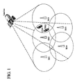
- FIG. 1 illustrates an example of typical cellular (including IEEE 802,22) deployment configuration
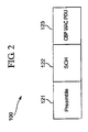
- FIG. 2 illustrates the structure of a CBP packet defined in IEEE 802.22
- FIG. 3 illustrates a method for synchronizing overlapping base stations, which does not consider the propagation delay between the CBP transmitter and the CBP receiver
- FIG. 4 illustrates establishment of synchronization between overlapping base stations
- FIG. 5 illustrates communication between two synchronized overlapping cells
- FIG. 6 illustrates a scenario for coexistence transmission
- FIG. 7 illustrates method for precisely synchronizing overlapping cells
- FIG. 8 illustrates another scenario for coexistence transmission
- FIG. 9 illustrates a method for synchronizing overlapping cells according to an embodiment of the present invention.
- FIG. 10 illustrates a specific example for synchronizing overlapping cells.
- the IEEE 802.22 takes the proactive approach (as specified in its Requirements Document) and mandates that the MAC should include self-coexistence protocols and algorithms as part of the initial standard conception and definition.
- the IEEE 802.22 takes the proactive approach (as specified in its Requirements Document) and mandates that the MAC should include self-coexistence protocols and algorithms as part of the initial standard conception and definition.
- multiple 802.22 BSs and CPEs may operate in the same vicinity and, provided appropriate measures are taken at the air interface level, self-interference may render the 802.22 system useless.
- Even if directional antennas are used at the CPEs (although this may be implementation dependent), self-coexistence issues are not at all overcome. This is further aggravated by the fact that the range of 802,22 coverage can go up to 100 Km, and hence its interference range and impact on other collocated 802.22 cells is larger than in any other existing unlicensed technology.
- FIG. 1 illustrates a scenario for coexistence transmission.
- Both Customer Premises Equipment_a (CPE_a) 105 and CPE_b 106 are located in an overlapping area between Cell_a 103 covered by Base Station_a (BS_a) 101 and Cell_b 104 covered by BS_b 3.02.
- CPE_a 105 transmits a Coexistence Beacon Protocol (CBP) packet in response to the direction of BS_a 101.
- CPE_b 106 receives the CBP packet and relays the message to its BS_b.
- CBP Coexistence Beacon Protocol
- the propagation delay between BS_a 101 and CPE_a 105 is ⁇ 1; the propagation delay between BS_b 102 and CPE_b 106 is ⁇ 2; and the propagation delay between CPE_a 105 and CPE_b 106 is ⁇ 3.
- beacon frames There are two types of beacon frames that can be used for intra-BS and inter-BS communication, and it is defined as the superframe header, which is transmitted by the BS in the beginning of every new superframe, The BS beacon is transmitted only by the BS.
- CBP packets are employed and which can be transmitted by CPEs and BSs.
- CBP packets are transmitted with the goal of improving self-coexistence amongst nearby IEEE 802,22 cells. These packets are transmitted under the control of the BS during an active self-coexistence window and share the same beacon MAC header, Since the goal of CBP packets is to improve self-coexistence, these CBP packets are sometimes refereed to as self coexistence beacons.
- the CBP packets provide information about the current cell as well as the CPE's traffic flows with its BS. Specifically, conveying the information about the traffic flows of a CPE with its BS is the responsibility of the Beacon IE, which is carried in the CBP packet payload and should appear in every CBP packet transmitted by a CPE.
- CBP packets can carry in the payload one or more information elements.
- the CBP packets transmitted by CPEs should carry at least one beacon IE in their payload, since the beacon IE provides the basic information required to enable self-coexistence.
- CBP packets transmitted by the CPE may also carry a single DC/US Boundary IE.
- CBP packets transmitted by the BS should carry at least one DSIUS Boundary IE, and may also carry one or more Beacon IE.
- the Beacon IE provides necessary and sufficient information about the CPE's traffic reservations with the BS (CPEs with no traffic reservations with the BS need not transmit CBP packets). At least one Beacon IE should be included in every CBP packet transmitted by CPEs. Stations (either CPEs or BSs) belonging to other IEEE 802.22 BSs and who receive a CBP packet, can then improve coexistence amongst BSs through a variety of mechanisms such as interference-free scheduling.
- the CBP protocol should be employed.
- the CBP is a best-effort protocol based on coexistence beacon transmissions. Given the mechanism for synchronization of overlapping BSs and also the fact that, as noted below, CPEs do not continuously stay locked to a BS, successful delivery of coexistence beacon transmissions has high probability.
- a CBP packet 100 includes a preamble 121, a SCH 122, and a CBP MAC Protocol Data Unit (PDU) 123.
- CBP packet 100 starts with a preamble 121 which should be common across all IEEE 802.22 networks, and which is different from the superframe preamble. After preamble 121, follows the SCH 122 transmission. By transmitting both SCH 121 (which contains information about the IEEE 802.22 cell) and the CBP MAC PDU 123 (which contains information about the CPE reservations with its BS), the transmitting CPE conveys all necessary information to allow for better self-coexistence.
- 802.22 entities i,e., CPEs and BSs
- CPEs and BSs are capable of transmitting beacons which provide its recipients enough information to achieve satisfactory and good coexistence amongst overlapping 802.22 cells.
- These beacons are intended for inter-cell communication and carry specific information about a CPE's cell of attachment and downstream/upstream bandwidth allocations with the BS.
- coexistence beacons are scheduled through the use of Coexistence Interval Usage Code (TUC) (both Passive and Active) which can be specified in UpStream (US)-MAP and DownStream (DS)-MAP messages.
- TUC Coexistence Interval Usage Code
- US UpStream
- DS DownStream
- the connection ID contained in the MAP IE indicates which CPEs should send the beacon within the specified scheduled time.
- This connection ID can be either unicast (e.g., a CPE's primary connection ID), multicast (i.e., a multicast management connection ID), or even the broadcast ID.
- the BS can implement clustering algorithms that improve spectrum utilization and maximize the effectiveness of the coexistence beacons, as multiple CPEs would transmit a coexistence beacon during the same scheduled time.
- the CPE should always verify if the connection ID specified by the BS includes itself or not. This will determine the CPE's behavior during the scheduled Coexistence IUC.
- the Coexistence IUC defines a period of time where channel access is contention based. In other words, during this time CPEs should use the contention access mechanism (see 0) to gain access to the medium and transmit the coexistence beacon.
- the reason why a contention-based access mechanism is preferred for sending coexistence beacons is that it maximizes the spectrum usage. In the majority of cases, it is anticipated that the BS will not schedule just a single CPE to transmit beacons, but rather will attempt to improve coexistence by scheduling multiple CPEs to send beacons within the same time span (multicast management connections can be used for this purpose). Furthermore, when combined with the clustering algorithms, the efficiency of this contention basing is maximized because, for the same Coexistence IUC, the BS will only schedule CPEs that do not belonging to the same physical cluster,
- a CPE does not stay locked to the BS at all times during a frame.
- a CPE will only be locked to the BS whenever it is scheduled to receive/send data from/to the BS as is indicated through the US-MAP and DS-MAP messages.
- the CPE will be listening to the medium and searching for a coexistence beacon.
- the probability of success and efficiency of the CBP is drastically increased.
- a CPE loses synchronization with BS while listening/receiving a coexistence beacon, it should regain synchronization in the beginning following frame, which will cause few, if any, side effects.
- Another mechanism that can be used by the BS to look out for CBP beacons is to schedule the Coexistence UIC in a Passive Mode.
- the Passive Mode defines a time where the CPEs does not perform any transmission but simply listens to the medium while on the look out for CBP packets and, possibly, BS SCH beacons.
- downstream/upstream bandwidth allocations made by BS-to-CFEs in a certain frame should not change for a number of consecutive frames. This guarantees that the information carried in coexistence beacons is valid for at least a minimum duration of time, thus allowing enough time to the recipients of the coexistence beacon to implement self-interference mitigation mechanisms as are discussed below. Further, at any time when a BS must allocate bandwidth to a CPE, it should always seek to allocate this bandwidth based on the previous allocations, if any, to this CPE. That is, the BS should always allocate bandwidth to a CPE using approximately the same combination of slot and logical channel.
- a CPE receives coexistence beacons from other collocated CPEs belonging to different cells, it can use this information in many ways in order to improve coexistence.
- the first thing a CPE may want to do is to convey to the BS the received information.
- the BS will implement so-called "interference-free" scheduling algorithm, which schedules the various upstream/downstream traffic from and to CPEs in such a way that these allocations do not intersect with the allocations of this CPE's interfering with other CPEs.
- Another use of this information is for bandwidth request purposes.
- the CPE may include constraint elements when requesting upstream bandwidth allocation to the BS, thus providing the information the BS would need to avoid allocating time for this CPE which interferes with other collocated CPEs.
- TRC-REQ Traffic Constraint Request
- CBP packets are used for multiple purposes in CMAC such as establishing and keeping synchronization, as well as for self-coexistence. Therefore, the process carried out at the BS to decide when and in which mode (i.e., passive or active) to schedule the Self-Coexistence IUC is mostly implementation dependent, while it is recommended that this be done every frame during normal operation,
- CMAC is capable, however, of providing the necessary information to assist the BS in this decision process.
- a decision criterion may be defined such that if the Packet Error Rate (PER) experienced by one or more CPEs (clustering can be used here) exceeds a predetermined threshold value per CBP, this would trigger the BS to schedule a Coexistence IUC for at least the corresponding CPEs.
- PER Packet Error Rate
- Another simpler strategy for the BS is to implement a pseudo-random process wherein self-coexistence windows are statically scheduled with a certain frequency, but the mode (i.e., whether passive and active) is pseudo-random.
- This process is denominated pseudo-random in the sense that it can take into account other statistics in the decision process, such as traffic pattern,
- a mandatory scheme that allows overlapping BS to synchronize by aligning their frames in time addresses the problem with an over-the-air approach, in the sense that the scheme does not rely on any sort of fixed backhaul infrastructure. This is not to say, however, that the scheme cannot operate over the backhaul.
- superframes should have the same and fixed length in terms of time, or at a minimum should be an integral multiple of each other.
- Individual frames within a superframe should also have the same and fixed size, and at a minimum should be an integral multiple of each other. This will facilitate not only in establishing synchronization amongst overlapping cells, but, most importantly, will maintain synchronization with very low overheads.
- An IEEE 802.22 cell should actively seek for other overlapping IEEE 802.22 cells in order to establish synchronization, as well as provide a technique by which other collocated cells can find it.
- two other mechanisms should also be used for this purpose which will considerably increase the probability of a successful synchronization: self-coexistence quiet periods and self-coexistence windows in both passive and active modes.
- the BS should also schedule quiet periods for the purpose of self-coexistence, and these are hereby called as self-coexistence quiet periods. Typically, however, these quiet periods need not be as frequent as those for the detection of incumbents, although the BS has complete freedom to choose their occurrence. In practice, self-coexistence quiet periods could be scheduled during low peak hours, such as overnight, without causing any major impact on the system performance and responsiveness. During this time, both CPEs and the BS will search for CBP or SCH packets transmitted by overlapping IEEE 802.22 terminals belonging to other IEEE 802.22 cells.
- a BS Whenever a BS powers up, it should never schedule self-coexistence windows in active mode (i.e., CBP transmissions) before at least one self-coexistence quiet period, This is done to ensure that, with high probability, a new IEEE 802.22 cell should first synchronize with any other collocated IEEE 802.22 cell before announcing its existence through CBP packets.
- active mode i.e., CBP transmissions
- Self-coexistence quiet periods should always be scheduled within the boundaries of a superframe, and should be scheduled in a random way to increase the probability that overlapping BSs successfully detect each other.
- the duration of a quiet period will typically be of one frame.
- the BS should randomly pick the frame number between [0, FS-1], while the superframe number should be derived from [0, NSTQP], where NSTQP is the Number of Superframes within an Incumbent Quiet Period.
- NSIQP can be easily derived from the TTQP field. By doing this, we are enforcing that the frequency of self-coexistence quiet periods should be the same as the incumbent quiet periods. Obviously, this can be dynamically changed by the BS if it can estimate an increment or decrement in the number of overlapping BSs (e.g., through PER statistics reported by CPEs or backhaul signaling).
- Self-Coexistence windows should also be used for this purpose, and should always be scheduled by the BS at the end of the US subframe.
- the first key difference between self-coexistence quiet periods and self-coexistence windows is the time granularity. While the former will typically take at least an entire frame, the latter happens within part of a frame.
- the second, and probably most significant, difference is that during the self-coexistence quiet periods CPEs and the BS do not perform any type of transmission, but only sense the channel.
- CPEs can transmit CBP packets if so scheduled by the BS (in the case of self-coexistence in active mode), A decision processes can be used at the BS to determine whether to schedule a passive or active self-coexistence period.
- FIG. 3 depicts the relationship between the Transmission Offset and Reception Offset fields for a frame of size FS (in units of symbols), wherein the propagation delay between BS1 and BS2 is small enough to be negligible.
- the Transmission Offset is marked relative to the beginning of the (super) frame at the BS1
- the Reception Offset is marked relative to the beginning of the (super) frame at the BS2 in the FIG. 3 .
- BSi responsible for cell i
- BSj responsible for a neighboring cell j
- Fs i - Frame_ Number i - 1 FDC i + FDC i - Reception_Offset - ( ( Fs j - Frame_ Number j - 1 ) ⁇ FDC j + FDC j - Transmission_Offset ) ⁇ FS i ⁇ FDC i + GuardBands ⁇
- Frame_ Number i is the frame number in which the CBP packet was received
- Frame_Numben j is the frame number in which the CBP packet was transmitted and should be -1 in the case of a SCH
- GuardBand is the guard band
- BSi should apply this convergence rule to each and every synchronization alternative available. Only those that satisfy this rule can proceed to the next phase.
- the BS should attempt synchronization with each overlapping BS, one at a time. Unless the BS realizes that it is already synchronized with the overlapping network corresponding to the selected packet (i.e., with Slide Amount equal to 0 or FS - see below -, or through bookkeeping), the BS should immediately construct and transmit a FSL-REQ message as a broadcast to all CPEs in the cell, and should not schedule any additional active mode self-coexistence interval until the scheduled time of the frame slide.
- the Slide Count and Slide Amount fields should be configured as depicted in FIG. 125.
- Slide Count should be equal to the number of frames right before the start of the superframe of the overlapping BSs, and Slide Amount will be equal to the number of slots to the start of the overlapping BS' superframe.
- the BS On the CPE side, it should report back to the BS on any received CBP or SCH packets, unless it receives a FSL-REQ message nom the BS in the meantime in which case it should terminate the self-coexistence procedure and return to normal operation. Regardless of whether it was the BS itself who detected the CBP or SCH packets, or if these were received as a result of a CPE report, the BS should proceed in the same way as described above in attempting synchronization.
- the key difference at the BS is that the CPEs who received the same SCH and CBP packets will report different values for the Reception Offset due to the fact that they experience different propagation delays. In this case, it is up to the discretion of the BS to select one of the packets, as these refer to the same network. To cope up with the different propagation delays, which consists essentially of allowing guard bands in Equation (1) and Equation (2).
- the BS Whenever sliding the frame to the left or to the right, the BS always should adopt the same behavior. That is, at the scheduled slide time the BS should initiate transmission of a new superframe (shown in FIG. 4 ). So that the frame slide does not disrupt any data communication, the BS scheduler should take this slide into account when scheduling US and DS transmissions.
- the frame slide operation may result in a partial frame as indicated in FIG. 4 . It is up to the BS to use this partial frame as it sees fit. For example, the BS could use this time as a quiet period. Another possibility is that the scheduler at the BS has the capability to schedule data transmissions during this time, and so airtime is not wasted. Yet another option would be to keep this partial frame as idle time, which may be a simple strategy whenever the partial frame size is only a few slots.
- the BS should schedule self-coexistence windows with a certain periodicity and always at the end of the US subframe.
- Confirmation and maintenance of synchronization is performed through periodic CBP packet transmissions and receptions during self-coexistence windows. Once the first CBP packet is successfully received from the overlapping cell, synchronization is completed and confirmed. At this point, the BS should continue to schedule self-coexistence windows, but now with the main purpose of better self-coexistence through the exchange of traffic constraints.
- a positive side effect of the transmission and reception of CBP packets is that the overlapping cells can more easily remain synchronized. This will, in effect, provide the most performance gains for all synchronized IEEE 802.22 cells.
- FIG. 5 shows an example of how two synchronized 802.22 cells communicate over the air through the self-coexistence window.
- the BS should schedule self-coexistence windows with an appropriate guard band, which is recommended to be at least three slots. In this way, the BS can provide a guard band and take into account the worst scenario for the transmission/reception of at least one CBP packet.
- a frame slide in a cell is the result of a report from one or more CPEs, together with the BS, these CPEs should be responsible for keeping track of the synchronization.
- the CPEs should periodically transmit/receive CBP packets to/from the synchronized cell in order to confirm continued synchronization.
- the CPE should not report to the BS on each and every CBP packet received. Rather, it should restrict its control information exchange with the BS to only those control information exchanges that are needed for better self-coexistence and to implement "interference-free scheduling".
- CPE_a 105 transmits a CBP, which is contained in a superframe.
- CPE_a 105 marks a "transmission offset" (Tx offset) of the CBP packet relative to the beginning of the superframe in Cell_a 103.
- the information of the transmission offset can be delivered by the CPE_a 105 (or BS_a 101).
- the transmission offset may include the information in MAC header, or information elements, or Protocol Data Unit (PDU) of the CBP packet, or predefined signal.
- the transmission offset can indicate the offset (in units of slots) relative to the start of the first slot of the PHY PDU (including preamble) where the current frame is transmitted.
- CPE_b 106 After detecting the CBP packet, CPE_b 106 marks a "reception offset" (Rx offset) relative to the beginning of the superframe in Cell_b 104. CPE_b 106 reports this event to BS_b 103.
- Rx offset reception offset
- BS_b 102 knows the difference between the transmission offset and the reception offset, thus aligning the superframe timing in Cell_b with that of Cell_a. For the first assumption, even though the CBP packet is transmitted by CPE_a 105, CPE_a 105 already makes sure the transmission offset is relative to BS_a 101.
- BS_b 102 can always assume this transmission offset is defined relative to BS_a 101.
- the same concept applies for the reception offset. Namely, although the reception offset is measured by CPE_b 106 and is reported to BS_b 102, BS_b 102 can always make sure that the reception offset is defined relative to itself, because either BS_b 102 or CPE_b 106 could consider the propagation delay between them so that the final reception offset is relative to BS_b 102. This is typically achieved by the ranging process. In other words, no matter how the CBP packet is transmitted and received, both of the transmission offset and the reception offset are assumed to be relative to the corresponding base stations.
- FIG. 7 Another example method of synchronization of overlapping cells is shown in FIG. 7 .
- BS_a 101 directly transmits a CBP packet 100 to BS_b 102.
- CBP packet 100 is transmitted by BS_a 101 at the transmission offset and is received by BS_b 102 after the propagation delay ⁇ BS_b 102 measured the reception offset.
- the sum of the transmission offset and the propagation delay ⁇ equals to the sum of the reception offset and the frame slide ⁇ .
- the propagation delay between the CBP transmitter and the CBP receiver i.e. ⁇ is very small in the FIG 3
- the propagation delay ⁇ is large enough and may not be negligible in this case.
- BS_b 102 cannot calculate the frame slide ⁇ , and thus BS_b 102 cannot synchronize its transmission with BS_a. Therefore, the synchronization accuracy is directly limited by this kind of propagation delay. In other words, the second assumption is not always legitimate. If the distance between the two base stations is 30 Km, the propagation delay could be about 100 ⁇ sec. As another case, BS_b could pick up the CBP packet from CPE_a directly. In this case, the propagation delay could easily be tens of microseconds, e.g., 10 Km cell radius could incur 33 ⁇ sec synchronization error.
- FIG. 8 Another scenario of coexistence transmission is illustrated in FIG, 8 , where CPRE_a 105 is located in an overlapping area between Cell_a 103 covered by BS_a 101 and Cell_b 104 covered by BS_b 102.
- CPE_a 105 transmits a CBP packet in response to the direction of BS_a 101.
- BS_b 102 receives the CBP packet.
- the propagation delay between BS_a 101 and CPE_a 105 is ⁇ 1, while the propagation delay between BS_b 102 and CPE_a 105 is ⁇ 2.
- the synchronization error could easily be tens of microseconds. Therefore, BS_b 102 cannot synchronize its transmission with BS_a 101 without the knowledge of propagation delay ⁇ 2.
- the present invention provides a method for precise network synchronization by considering propagation delay when transmitting the CBP packet.
- the alternative method is to include the location information of the transmitter in the CBP packet.
- the receiver should know its own location already.
- the receiver could be a CPE or a BS. Then the propagation delay might be addressed by transmit-feedback handshaking.
- a BS It should be mandatory to require a BS to know the locations of neighboring BSs in order to support cell synchronization over the air. This information could be acquired through provisioning during cell installation. But, there may be an issue if cells from different vendors are required to be synchronized, when the vendors do not want to share the location information.
- the other solution would be to include the message of the location of a BS at each SCH transmitted by the BS, so that a neighboring BS can calculate and cancel out the propagation delay between the BS and the neighboring BS to achieve cell synchronization.
- a problem with this method is that each SCH has to carry the overhead with the message of location.
- propagation delay is considered when synchronizing overlapping cells.
- the transmitter transmits a CBP packet carrying location information of the transmitter, so that the receiver can calculate and cancel out the propagation delay to achieve cell synchronization.
- the location information can be delivered by SCH (Superframe Control Header) which includes location configuration Information Element (IE), or by CBP which includes location IE.
- IE location configuration Information Element
- the receiver can report the calculated propagation delay to the BS which covers or services the receiver, Alternatively, the receiver may report the location information of the transmitter to the BS which covers or services the receiver, and the BS may calculate the propagation delay based on the location information. If the BS also needs to know location information of the receiver, then the receiver is able to transmit the location information of both the receiver and the transmitter.
- This method requires the transmitters to have a location solution using, for example, the Global Positioning System (GPS).
- GPS Global Positioning System
- the transmitter ID rather than the exact location could be included in the CBP message. Then the receiver can retrieve the location of the transmitter from the location database using the ID.
- the overhead of including location information in CBP message could be cut short, given that the receiver knows the exact location of the receiver, and the receiver knows the transmitter is within a certain radius (e.g., the transmitter and the receiver is within 50Km from each other). In other words, only the least important bits may be enough for inferring the exact location of the transmitter.
- the transmitter measures inter-cell delays using two-way communication and carries the information regarding the propagation delays in the CBP packet.
- the inter-cell delay may be ⁇ 3 in the scenario illustrated in FIG. 6 , or ⁇ 2 in the scenario illustrated in FIG. 8 .
- a new transmission procedure is needed for measuring the inter-cell delay no matter the inter-cell delay occurs between two CPEs, or between a BS and a CPE. Basically, the measurement requires an immediate follow-up transmission in order to measure the propagation delay.
- CBP packets are scheduled by BSs through a Self-Coexistence window.
- the Self-Coexistence window defines a period of time where channel access is contention bases, in order to maximize spectrum usage.
- CPEs should use the contention access mechanism to gain access to the medium and transmit the CBP packet.
- BS_a selects some CPEs (e.g., CPE_a1, CPE_a2 and CPE_a3) for transmitting a CBP packet in a contention manner (e.g., with the contention window of [0 - 7]). That is, CPE_a1, CPE_a2 and CPE_a3 contend for the transmission of the CBP packet.
- BS_a may assign only one CPE (e.g., CPE_a1) to transmit the CBP packet.
- BS_b selects some CPEs (e.g., CPE_b1, CPE_b2 and CPE_b3) for receiving the CBP packet.
- CPE_b1, CPE_b2 and CPE_b3 contend for the transmission of the follow-up message.
- the original CBP transmitter receives the feedback (i.e., the follow-up message) and calculates the propagation delay between the transmitter and the receiver. As a result, precise cell synchronization is established.
- the CPE_ai which won the contention for transmitting the first CBP packet may transmit another follow up message to the CPE_bi,
- FIG. 10 One example of this process is illustrated in FIG. 10 , where BS_a selects CPE_a1, CPE_a2 and CPE_a3 located in cell_a to content for transmitting a first CBP packet in contention window 201.
- CPE a1 wins the contention and transmits a first CBP packet at time t 0 .
- the packet reaches the CPE_b's (e.g., CPE_b1, CPE_b2 and CPE_b3) in cell_b after a certain propagation delay, shown as ⁇ 3 in the figure, at slightly different time.
- CPB_b2 receives the packet.
- CPE_b1 , CPE_b2 and CPE_b3 content for the transmission of a second CBP packet (i.e., follow up message) in contention window 202.
- CPE_b2 wins the contention and transmits the second CBP packet at time t 2 .
- This packet reaches CPE_a1 after a certain propagation delay, shown again as ⁇ 3 in the figure. That is, at time t 4 , CPE_a1 receives the second CBP packet.
- the other CPE_as in cell_a might also receive the second CBP packet, but they cannot use the second CBP packet for calculating the propagation delay because they did not transmit the first CBP packet.
- CPE_a1 calculates the propagation delay between CPE_a1 and CPE_b2; the resulted propagation delay is ( t 4 - t 0 ) / 2. As a result, precise cell synchronization is accomplished.
- the first CBP transmitter i.e., CPE_a1 may send another follow-up message, i.e., a third CBP packet at time t 5 .
- CPE_b2 receives this third CBP packet at t6.
- CPE_b2 could calculate the propagation delay between CPE_b2 and CPE_a1; the resulted propagation delay is ( t 6 - t 2 ) / 2.
- BSs and CPEs could have a certain processing delay in transmitting and receiving CBP and SCH packets. These kinds of delay should be compensated if they are substantial. Generally, they won't be in practice.
- the propagation delay between CPE_a and CPE_b is calculated using the round-trip communication. At t 0 CPE_a transmits a packet, at t 1 CPE_b receives the packet, at t 2 CPE_b transmits another packet, at t 3 CPE_a receives the packet. After the process, CPE_a measures t 3 - t 0 The value of t 2 - t 1 is the processing delay at CPE_b.
- t 3 - t 0 is the round-trip propagation delay between CPE_a and CPE_b.
- the one-way propagation delay between CPE_a and CPE_b equals to the half of the round-trip propagation delay. Therefore, t 2 - t 1 affect the precision of the propagation delay, and thus the precision of the inter-BS synchronization.
- this processing delay is negligible if we are talking about obtaining the precision of 25 ⁇ s for inter-BS synch
- Intra-cell delay can be measured by the ranging process. That is, all the CPEs in a cell align their transmission by the coordination of the BS via the ranging process. In other words, the BS measures the propagation delay of each CPE relative to the BS. Therefore, in the scenario as shown in FIG. 8 , ⁇ 1 is known by regular 'ranging' process between BS_a 101 and CPE_a 105, but, ⁇ 2 is not known because CPE_a 105 is not associated with BS_b 102. Similarly, in the scenario as shown in FIG. 6 , ⁇ 1 and ⁇ 2 are known, whereas ⁇ 3 is not known.
- the transmission offset is relative to BS_a 101
- the reception offset is relative to BS_b 102, even though the transmitter and receiver of the CPE packets might be CPEs.
- the reason is that the propagation delay between BSa and CPEa, BSb and CPEb are known, and are removed in the equations.
Landscapes
- Engineering & Computer Science (AREA)
- Computer Networks & Wireless Communication (AREA)
- Signal Processing (AREA)
- Mobile Radio Communication Systems (AREA)
Applications Claiming Priority (2)
| Application Number | Priority Date | Filing Date | Title |
|---|---|---|---|
| US87117406P | 2006-12-21 | 2006-12-21 | |
| US11/957,292 US8446893B2 (en) | 2006-12-21 | 2007-12-14 | Enhanced coexistence beacon protocol (ECBP) for precise intercell synchronization of overlapping wireless base stations |
Publications (2)
| Publication Number | Publication Date |
|---|---|
| EP1936838A2 true EP1936838A2 (de) | 2008-06-25 |
| EP1936838A3 EP1936838A3 (de) | 2010-05-05 |
Family
ID=39272268
Family Applications (1)
| Application Number | Title | Priority Date | Filing Date |
|---|---|---|---|
| EP07024772A Withdrawn EP1936838A3 (de) | 2006-12-21 | 2007-12-20 | Verfahren zur Synchronisierung von überlappenden Zellen und entsprechendes drahtloses Kommunikationssystem |
Country Status (5)
| Country | Link |
|---|---|
| US (1) | US8446893B2 (de) |
| EP (1) | EP1936838A3 (de) |
| KR (1) | KR100930521B1 (de) |
| AU (1) | AU2007334906A1 (de) |
| WO (1) | WO2008075921A1 (de) |
Cited By (4)
| Publication number | Priority date | Publication date | Assignee | Title |
|---|---|---|---|---|
| CN102100016A (zh) * | 2008-07-14 | 2011-06-15 | 三星电子株式会社 | 在基于认知无线电的无线通信系统中发送共存信标协议包的设备和方法 |
| WO2012007912A1 (en) * | 2010-07-15 | 2012-01-19 | Koninklijke Philips Electronics N.V. | Methods and system for efficient self-coexistence of wireless regional area networks |
| WO2012026935A1 (en) * | 2010-08-26 | 2012-03-01 | Thomson Licensing | White space usage for wireless local area network devices |
| US9485785B2 (en) | 2008-07-14 | 2016-11-01 | Samsung Electronics Co., Ltd. | Apparatus and method for transmitting coexistence beacon protocol packet in cognitive radio based wireless communication system |
Families Citing this family (36)
| Publication number | Priority date | Publication date | Assignee | Title |
|---|---|---|---|---|
| US7869400B2 (en) * | 2006-10-16 | 2011-01-11 | Stmicroelectronics, Inc. | Method of inter-system coexistence and spectrum sharing for dynamic spectrum access networks-on-demand spectrum contention |
| US8494546B2 (en) | 2006-10-16 | 2013-07-23 | Stmicroelectronics, Inc. | Method of inter-system communications dynamic spectrum access network systems-logical control connections |
| US8254922B2 (en) | 2006-10-16 | 2012-08-28 | Stmicroelectronics, Inc. | Zero delay frequency switching with dynamic frequency hopping for cognitive radio based dynamic spectrum access network systems |
| US7965786B2 (en) | 2007-02-22 | 2011-06-21 | Stmicroelectronics, Inc. | Clean sensing for dynamic frequency hopping in dynamic spectrum access networks |
| US8437314B2 (en) | 2007-02-22 | 2013-05-07 | Stmicroelectronics, Inc. | Radio frequency architecture for spectrum access networks |
| US8199707B2 (en) | 2007-05-11 | 2012-06-12 | Stmicroelectronics, Inc. | Inter-cell discovery and communication using time division multiple access coexistence beaconing protocol |
| US8780852B2 (en) | 2007-05-11 | 2014-07-15 | Stmicroelectronics, Inc. | Multi-channel inter base-station communication |
| US8411622B2 (en) * | 2007-05-11 | 2013-04-02 | Stmicroelectronics, Inc. | Multi-channel inter base-station communication |
| CN101483511B (zh) * | 2008-01-09 | 2013-09-18 | 三星电子株式会社 | 适用于多tdd系统共存的方法 |
| US8824432B2 (en) * | 2008-01-16 | 2014-09-02 | Stmicroelectronics, Inc. | Beaconing period framing for efficient multi-channel inter-cell communications in cognitive radio networks |
| US8780882B2 (en) * | 2008-01-16 | 2014-07-15 | Stmicroelectronics, Inc. | On-demand spectrum contention for inter-cell spectrum sharing in cognitive radio networks |
| KR20090092431A (ko) * | 2008-02-27 | 2009-09-01 | 삼성전자주식회사 | 인지무선시스템에서 씨비피 전송을 위한 장치 및 방법 |
| US8325765B2 (en) * | 2008-12-05 | 2012-12-04 | Stmicroelectronics, Inc. | Super-frame structure for dynamic spectrum sharing in wireless networks |
| US20100142463A1 (en) * | 2008-12-05 | 2010-06-10 | Stmicroelectronics, Inc. | Frame-based on-demand spectrum contention protocol-messaging method |
| US8521823B1 (en) * | 2009-09-04 | 2013-08-27 | Google Inc. | System and method for targeting information based on message content in a reply |
| CN102056251B (zh) * | 2009-11-04 | 2013-04-03 | 中国移动通信集团公司 | 一种网络切换的方法、系统及设备 |
| US8451789B2 (en) | 2010-06-15 | 2013-05-28 | Nokia Corporation | Method to request resources in TV white spaces type environment |
| US8385286B2 (en) * | 2010-09-03 | 2013-02-26 | Nokia Corporation | Resource sharing between secondary networks |
| US8412247B2 (en) * | 2010-09-03 | 2013-04-02 | Nokia Corporation | Method for generating a coexistence value to define fair resource share between secondary networks |
| WO2012036362A1 (ko) * | 2010-09-16 | 2012-03-22 | 동국대학교 산학협력단 | 인컴번트 신호 검출 및 채널 할당을 위한 장치 및 방법 |
| US8363602B2 (en) | 2011-01-14 | 2013-01-29 | Nokia Corporation | Method, apparatus and computer program product for resource allocation of coexistent secondary networks |
| US8514802B2 (en) | 2011-05-04 | 2013-08-20 | Nokia Corporation | Method to evaluate fairness of resource allocations in shared bands |
| US8929831B2 (en) | 2011-07-18 | 2015-01-06 | Nokia Corporation | Method, apparatus, and computer program product for wireless network discovery based on geographical location |
| US8730990B2 (en) * | 2011-09-15 | 2014-05-20 | Nokia Corporation | Method, apparatus, and computer program product for quiet period management in wireless networks for coexistence |
| US9019909B2 (en) | 2011-12-06 | 2015-04-28 | Nokia Corporation | Method, apparatus, and computer program product for coexistence management |
| US8909274B2 (en) | 2012-03-12 | 2014-12-09 | Nokia Corporation | Method, apparatus, and computer program product for resource allocation conflict handling in RF frequency bands |
| US9473946B2 (en) | 2012-03-12 | 2016-10-18 | Nokia Technologies Oy | Method, apparatus, and computer program product for temporary release of resources in radio networks |
| US8942701B2 (en) | 2012-08-14 | 2015-01-27 | Nokia Corporation | Method, apparatus, and computer program product for transferring responsibility between network controllers managing coexistence in radio frequency spectrum |
| US9107089B2 (en) | 2012-11-09 | 2015-08-11 | Nokia Technologies Oy | Method, apparatus, and computer program product for location based query for interferer discovery in coexistence management system |
| CN105532054B (zh) * | 2013-09-16 | 2019-07-02 | Lg电子株式会社 | 网络同步的方法和装置 |
| KR102150936B1 (ko) * | 2013-12-26 | 2020-09-03 | 한국전자통신연구원 | 인지 무선 네트워크에서 초기 레인징 수행 방법 및 그 시스템 |
| US10299284B2 (en) * | 2015-08-31 | 2019-05-21 | Qualcomm, Incorporated | Inter-access terminal unblocking and enhanced contention for co-existence on a shared communication medium |
| HK1257200A1 (zh) * | 2016-05-11 | 2019-10-18 | Oppo广东移动通信有限公司 | 通信方法和通信设备 |
| KR102250450B1 (ko) * | 2016-06-20 | 2021-05-12 | 현대자동차주식회사 | 네트워크에서 오류 검출을 위한 통신 노드의 동작 방법 |
| US10623291B2 (en) * | 2016-06-20 | 2020-04-14 | Hyundai Motor Company | Operation method of communication node for detecting link errors in network |
| US20240223429A1 (en) * | 2021-05-07 | 2024-07-04 | Sony Group Corporation | Coverage enhancing devices providing ofdm symbol delays |
Family Cites Families (37)
| Publication number | Priority date | Publication date | Assignee | Title |
|---|---|---|---|---|
| CA2107606A1 (en) | 1992-10-07 | 1994-04-08 | Keishi Matsuno | Method of establishing inter-base-station synchronization and mobile radio communication system using the method |
| FI106824B (fi) * | 1993-07-05 | 2001-04-12 | Nokia Networks Oy | Tukiasema |
| JP3244610B2 (ja) * | 1995-01-27 | 2002-01-07 | 株式会社日立製作所 | 周波数ホッピング方式無線lanシステム |
| KR0140130B1 (ko) * | 1995-03-07 | 1998-07-01 | 김주용 | 디지탈이동통신 시스템 장치 및 각 서브시스템 간의 타이밍 설계 방법 |
| US5745484A (en) * | 1995-06-05 | 1998-04-28 | Omnipoint Corporation | Efficient communication system using time division multiplexing and timing adjustment control |
| US5959980A (en) * | 1995-06-05 | 1999-09-28 | Omnipoint Corporation | Timing adjustment control for efficient time division duplex communication |
| US5903823A (en) * | 1995-09-19 | 1999-05-11 | Fujitsu Limited | Radio apparatus with distortion compensating function |
| US5864549A (en) | 1996-07-24 | 1999-01-26 | Nokia Mobile Phones, Ltd. | Method for the overlayed operation of two radio communication systems with reduced intersystem interference, and a radio communication system for overlayed use |
| JP3323760B2 (ja) * | 1996-11-07 | 2002-09-09 | 株式会社日立製作所 | スペクトラム拡散通信システム |
| US7031295B2 (en) * | 1996-11-07 | 2006-04-18 | Harris Corporation | System and method for minimizing guard time in a time division duplex communication system |
| US6359869B1 (en) | 1997-06-25 | 2002-03-19 | Nec Corporation | Mobile communication system capable of establishing frame syncronization among base stations |
| US5959982A (en) * | 1997-08-29 | 1999-09-28 | Adicom Wireless, Inc. | Method and apparatus for adapting a time division duplex timing device for propagation delay |
| WO1999017470A1 (en) | 1997-09-29 | 1999-04-08 | Telefonaktiebolaget Lm Ericsson (Publ) | A broadcast control channel structure for wideband tdma |
| EP1080555B1 (de) | 1998-05-04 | 2009-08-12 | Nokia Corporation | Verfahren zur synchronisierung eines basisstationennetzwerks |
| AU8798798A (en) | 1998-06-08 | 1999-12-30 | Nokia Networks Oy | A method for synchronization of a cellular radio network |
| US6377565B1 (en) * | 1998-09-29 | 2002-04-23 | General Electric Company | Adaptive propagation delay compensation for TDMA communications systems |
| US6332069B1 (en) * | 1999-02-10 | 2001-12-18 | Hughes Electronics Corporation | Apparatus and method for grouping carriers to minimize the occurrence of call blocking in a satellite-based communications network |
| JP3658234B2 (ja) * | 1999-03-17 | 2005-06-08 | 富士通株式会社 | 無線電話システムにおける遅延補正システム |
| US6701127B1 (en) * | 1999-12-16 | 2004-03-02 | General Dynamics Decision Systems, Inc. | Burst communications method and apparatus |
| US6993009B2 (en) * | 2000-03-10 | 2006-01-31 | Hughes Electronics Corporation | Method and apparatus for deriving uplink timing from asynchronous traffic across multiple transport streams |
| KR100419409B1 (ko) | 2000-06-24 | 2004-02-19 | 삼성전자주식회사 | 동기 부호분할다중접속 통신시스템의 역방향 동기 전송방식에 대한 동기화를 위한 장치 및 방법 |
| CN1214553C (zh) | 2000-11-17 | 2005-08-10 | 三星电子株式会社 | 在窄带时分双工码分多址移动通信系统中测量传播延迟的设备和方法 |
| US20020160787A1 (en) * | 2001-03-13 | 2002-10-31 | Lucent Technologies Inc. | Communications system and related method for determining a position of a mobile station |
| US7454217B2 (en) * | 2001-10-04 | 2008-11-18 | Stephen William Edge | Method and apparatus for wireless network timekeeping and synchronization |
| NO20016372D0 (no) * | 2001-12-27 | 2001-12-27 | Ericsson Telefon Ab L M | Arrangement for å redusere minnebehovet i en svitsj |
| US7248889B2 (en) * | 2002-03-08 | 2007-07-24 | Nokia Corporation | Method and device for controlling the power in an asymmetric soft handover condition |
| US20030210713A1 (en) * | 2002-05-13 | 2003-11-13 | Hisham Abdel-Ghaffar | Estimating a time offset between link points in a communication network operating in a frequency division duplex mode |
| KR20040062828A (ko) * | 2003-01-03 | 2004-07-09 | 삼성전자주식회사 | 이동통신 시스템에서 이동통신 단말기의 plmn획득방법및 기지국의 plmn 정보제공방법 및 그 방법을수행하는 기지국 |
| US7643515B2 (en) * | 2004-11-10 | 2010-01-05 | Qualcomm Incorporated | Method and apparatus for deriving transmission timing of a downlink control channel in support of enhanced uplink operation |
| EP1882309B1 (de) * | 2005-05-10 | 2016-11-09 | Qualcomm Incorporated | Synchronisation einer basisstation über eine benutzervorrichtung mit mehreren kommunikationsmodi |
| JP5058170B2 (ja) * | 2005-11-07 | 2012-10-24 | エージェンシー フォー サイエンス, テクノロジー アンド リサーチ | 複数の利用可能周波数域を判定する方法及び装置 |
| JP4544240B2 (ja) * | 2005-11-21 | 2010-09-15 | Jfeスチール株式会社 | 管体の超音波探傷装置および超音波探傷方法 |
| KR100666695B1 (ko) * | 2005-11-29 | 2007-01-11 | 삼성전자주식회사 | 지연시간을 감소시킨 통신시스템 |
| US7656855B2 (en) * | 2006-04-29 | 2010-02-02 | At&T Intellectual Property Ii, Lp | Arrangement for synchronizing access points in WLAN using direct-sequence spread spectrum signaling |
| US20080062957A1 (en) * | 2006-09-11 | 2008-03-13 | Motorola, Inc. | Method and apparatus for aligned transmissions in a wireless network |
| US8249616B2 (en) * | 2007-08-23 | 2012-08-21 | Texas Instruments Incorporated | Satellite (GPS) assisted clock apparatus, circuits, systems and processes for cellular terminals on asynchronous networks |
| KR20090078723A (ko) * | 2008-01-15 | 2009-07-20 | 삼성전자주식회사 | 무선 이동 통신 시스템에서 복합 자동 재송신 요구 방식에 기반한 신호 송수신 방법 |
-
2007
- 2007-12-14 US US11/957,292 patent/US8446893B2/en not_active Expired - Fee Related
- 2007-12-18 KR KR1020070133688A patent/KR100930521B1/ko not_active Expired - Fee Related
- 2007-12-20 EP EP07024772A patent/EP1936838A3/de not_active Withdrawn
- 2007-12-21 WO PCT/KR2007/006741 patent/WO2008075921A1/en not_active Ceased
- 2007-12-21 AU AU2007334906A patent/AU2007334906A1/en not_active Abandoned
Cited By (13)
| Publication number | Priority date | Publication date | Assignee | Title |
|---|---|---|---|---|
| CN102100016A (zh) * | 2008-07-14 | 2011-06-15 | 三星电子株式会社 | 在基于认知无线电的无线通信系统中发送共存信标协议包的设备和方法 |
| US9485785B2 (en) | 2008-07-14 | 2016-11-01 | Samsung Electronics Co., Ltd. | Apparatus and method for transmitting coexistence beacon protocol packet in cognitive radio based wireless communication system |
| CN102986264B (zh) * | 2010-07-15 | 2016-05-18 | 皇家飞利浦电子股份有限公司 | 用于无线区域网的有效自共存的方法和系统 |
| CN102986264A (zh) * | 2010-07-15 | 2013-03-20 | 皇家飞利浦电子股份有限公司 | 用于无线区域网的有效自共存的方法和系统 |
| WO2012007912A1 (en) * | 2010-07-15 | 2012-01-19 | Koninklijke Philips Electronics N.V. | Methods and system for efficient self-coexistence of wireless regional area networks |
| TWI562654B (en) * | 2010-07-15 | 2016-12-11 | Koninkl Philips Electronics Nv | Methods and system for efficient self-coexistence of wireless regional area networks |
| US9699691B2 (en) | 2010-07-15 | 2017-07-04 | Koninklijke Philips N.V. | Methods and system for efficient self-coexistence of wireless regional area networks |
| US10015700B2 (en) | 2010-07-15 | 2018-07-03 | Koninklijke Philips N.V. | Methods and system for efficient self-coexistence of wireless regional area networks |
| EP2609700A1 (de) * | 2010-08-26 | 2013-07-03 | Thomson Licensing | White-space-nutzung für wlan-vorrichtungen |
| US9282557B2 (en) | 2010-08-26 | 2016-03-08 | Thomson Licensing | White space usage for wireless local area network devices |
| WO2012026935A1 (en) * | 2010-08-26 | 2012-03-01 | Thomson Licensing | White space usage for wireless local area network devices |
| US9491756B2 (en) | 2010-08-26 | 2016-11-08 | Thomson Licensing | White space usage for wireless local area network devices |
| US9839033B2 (en) | 2010-08-26 | 2017-12-05 | Thomson Licensing | White space usage for wireless local area network devices |
Also Published As
| Publication number | Publication date |
|---|---|
| AU2007334906A1 (en) | 2008-06-26 |
| KR100930521B1 (ko) | 2009-12-09 |
| WO2008075921A1 (en) | 2008-06-26 |
| KR20080058217A (ko) | 2008-06-25 |
| US8446893B2 (en) | 2013-05-21 |
| US20080159258A1 (en) | 2008-07-03 |
| EP1936838A3 (de) | 2010-05-05 |
Similar Documents
| Publication | Publication Date | Title |
|---|---|---|
| US8446893B2 (en) | Enhanced coexistence beacon protocol (ECBP) for precise intercell synchronization of overlapping wireless base stations | |
| US9801073B2 (en) | Method for improving self-coexistence of wireless communication networks | |
| CN101305627B (zh) | 用于改善无线通信网络的自共存性的方法 | |
| US7400894B2 (en) | Method for decentralized synchronization in a self-organizing radio communication system | |
| EP2670066B1 (de) | Aufwärtsstrecken-kanalkonfigurationsverfahren in einem funkkommunikationssystem | |
| US9918268B2 (en) | Communication control device, communication control method, radio communication system, base station, and terminal device | |
| US7953066B2 (en) | Method for synchronizing radio communication system divided into radio cells | |
| US20070223419A1 (en) | Method and system for sharing spectrum in a wireless communications network | |
| US20100290372A1 (en) | Method for multiple tdd systems coexistence | |
| CN102427606A (zh) | 应用于通信网络的传送站和接收站及其操作方法 | |
| EP2869615B1 (de) | System, vorrichtung und verfahren zur dynamisch getriggerten spektralabtastung in einem kognitiven funksystem | |
| US20250176008A1 (en) | Subscriber in a wireless communication system, base station, method for receiving data and computer program, for increasing the probability of getting through for subscribers with poor reception conditions or high qos requirements in communication systems with a high density of subscribers | |
| JP2023504539A (ja) | 隣接チャネル干渉緩和のための方法および装置 | |
| Auer et al. | Interference aware medium access for dynamic spectrum sharing | |
| US9357554B2 (en) | Method and apparatus for coexistence of multiple operating entity systems | |
| US6442402B2 (en) | Method and radio communication system for data transmission | |
| Omiyi et al. | Improving time-slot allocation in 4/sup th/generation OFDM/TDMA TDD radio access networks with innovative channel-sensing | |
| CN101569140A (zh) | 用于重叠的无线基站的精确小区间同步的增强的共存信标协议(ecbp) | |
| JP4567680B2 (ja) | 複数の無線セルに分割された無線通信システムの同期合わせ方法 | |
| WO2015101974A1 (en) | Protection in shared frequency bands of lte networks | |
| US10951380B1 (en) | Optimizing uplink synchronization via dynamic PRACH configuration | |
| KR101464701B1 (ko) | 이동통신 시스템에서 동일대역 간섭 완화를 위한 오프셋 프레임 구성 및 전송을 위한 장치 및 방법 | |
| JP4613224B2 (ja) | ビジー信号用トランシーバ | |
| WO2024170476A1 (en) | Methods, communications devices and infrastructure equipment | |
| CN120111503A (zh) | 一种无线网络通信方法、装置、存储介质及程序产品 |
Legal Events
| Date | Code | Title | Description |
|---|---|---|---|
| PUAI | Public reference made under article 153(3) epc to a published international application that has entered the european phase |
Free format text: ORIGINAL CODE: 0009012 |
|
| 17P | Request for examination filed |
Effective date: 20071220 |
|
| AK | Designated contracting states |
Kind code of ref document: A2 Designated state(s): AT BE BG CH CY CZ DE DK EE ES FI FR GB GR HU IE IS IT LI LT LU LV MC MT NL PL PT RO SE SI SK TR |
|
| AX | Request for extension of the european patent |
Extension state: AL BA HR MK RS |
|
| PUAL | Search report despatched |
Free format text: ORIGINAL CODE: 0009013 |
|
| AK | Designated contracting states |
Kind code of ref document: A3 Designated state(s): AT BE BG CH CY CZ DE DK EE ES FI FR GB GR HU IE IS IT LI LT LU LV MC MT NL PL PT RO SE SI SK TR |
|
| AX | Request for extension of the european patent |
Extension state: AL BA HR MK RS |
|
| 17Q | First examination report despatched |
Effective date: 20100722 |
|
| AKX | Designation fees paid |
Designated state(s): DE FR GB IT NL |
|
| STAA | Information on the status of an ep patent application or granted ep patent |
Free format text: STATUS: THE APPLICATION IS DEEMED TO BE WITHDRAWN |
|
| 18D | Application deemed to be withdrawn |
Effective date: 20101202 |