EP1936645B1 - Interrupteur pour produire une connexion et une interruption brusques des contacts électriques - Google Patents
Interrupteur pour produire une connexion et une interruption brusques des contacts électriques Download PDFInfo
- Publication number
- EP1936645B1 EP1936645B1 EP06256509.8A EP06256509A EP1936645B1 EP 1936645 B1 EP1936645 B1 EP 1936645B1 EP 06256509 A EP06256509 A EP 06256509A EP 1936645 B1 EP1936645 B1 EP 1936645B1
- Authority
- EP
- European Patent Office
- Prior art keywords
- switch
- contact
- carriage
- transfer
- actuator
- Prior art date
- Legal status (The legal status is an assumption and is not a legal conclusion. Google has not performed a legal analysis and makes no representation as to the accuracy of the status listed.)
- Active
Links
- 230000004888 barrier function Effects 0.000 claims description 23
- 238000004146 energy storage Methods 0.000 claims description 4
- 239000003990 capacitor Substances 0.000 description 3
- 230000006835 compression Effects 0.000 description 3
- 238000007906 compression Methods 0.000 description 3
- 230000000994 depressogenic effect Effects 0.000 description 3
- 238000003466 welding Methods 0.000 description 3
- XEEYBQQBJWHFJM-UHFFFAOYSA-N Iron Chemical compound [Fe] XEEYBQQBJWHFJM-UHFFFAOYSA-N 0.000 description 2
- 238000010276 construction Methods 0.000 description 2
- 238000010413 gardening Methods 0.000 description 2
- 229910000831 Steel Inorganic materials 0.000 description 1
- 230000010354 integration Effects 0.000 description 1
- 229910052742 iron Inorganic materials 0.000 description 1
- 238000004519 manufacturing process Methods 0.000 description 1
- 239000000463 material Substances 0.000 description 1
- 238000000034 method Methods 0.000 description 1
- 239000000203 mixture Substances 0.000 description 1
- 230000002040 relaxant effect Effects 0.000 description 1
- 239000010959 steel Substances 0.000 description 1
- 230000007704 transition Effects 0.000 description 1
Images


Classifications
-
- H—ELECTRICITY
- H01—ELECTRIC ELEMENTS
- H01H—ELECTRIC SWITCHES; RELAYS; SELECTORS; EMERGENCY PROTECTIVE DEVICES
- H01H5/00—Snap-action arrangements, i.e. in which during a single opening operation or a single closing operation energy is first stored and then released to produce or assist the contact movement
- H01H5/04—Energy stored by deformation of elastic members
- H01H5/045—Energy stored by deformation of elastic members making use of cooperating spring loaded wedging or camming parts between operating member and contact structure
-
- H—ELECTRICITY
- H01—ELECTRIC ELEMENTS
- H01H—ELECTRIC SWITCHES; RELAYS; SELECTORS; EMERGENCY PROTECTIVE DEVICES
- H01H13/00—Switches having rectilinearly-movable operating part or parts adapted for pushing or pulling in one direction only, e.g. push-button switch
- H01H13/50—Switches having rectilinearly-movable operating part or parts adapted for pushing or pulling in one direction only, e.g. push-button switch having a single operating member
- H01H13/62—Switches having rectilinearly-movable operating part or parts adapted for pushing or pulling in one direction only, e.g. push-button switch having a single operating member the contact returning to its original state upon manual release of a latch
-
- H—ELECTRICITY
- H01—ELECTRIC ELEMENTS
- H01H—ELECTRIC SWITCHES; RELAYS; SELECTORS; EMERGENCY PROTECTIVE DEVICES
- H01H13/00—Switches having rectilinearly-movable operating part or parts adapted for pushing or pulling in one direction only, e.g. push-button switch
- H01H13/02—Details
- H01H13/04—Cases; Covers
- H01H13/08—Casing of switch constituted by a handle serving a purpose other than the actuation of the switch
-
- H—ELECTRICITY
- H01—ELECTRIC ELEMENTS
- H01H—ELECTRIC SWITCHES; RELAYS; SELECTORS; EMERGENCY PROTECTIVE DEVICES
- H01H9/00—Details of switching devices, not covered by groups H01H1/00 - H01H7/00
- H01H9/02—Bases, casings, or covers
- H01H9/06—Casing of switch constituted by a handle serving a purpose other than the actuation of the switch, e.g. by the handle of a vacuum cleaner
Definitions
- the invention relates to a system and method for minimizing arcing and contact welding between electrical contacts in an on/off switch.
- the invention relates more particularly to a circuit interrupter that produces a snap-action connection and disconnection between the electrical contacts.
- Electrical circuits of various kinds are susceptible to a number of unfavorable conditions.
- arcing or sparking may occur between electrical contacts when such paired contacts bounce or partially separate upon toggling the switch to the off position.
- This condition is referred to as a teasable condition in an electrical system.
- the contacts of such an electrical system may weld together causing the circuit to remain closed even after the switch has been in the off position for a number of cycles.
- Such an on/off switch is commonly used in the triggers of hand operated devices such as main line powered construction tools and latterly powered gardening tools.
- the contact pressure directly relates to the trigger travel (i.e., the distance over which the trigger is moved or depressed).
- the user directly controls the trigger travel by pulling and relaxing his finger over the trigger.
- the contact pressure between electrical contacts in the switch may approach zero when a user only partially toggles the trigger to the on position.
- the contacts may weld together.
- the circuit will remain closed.
- the powered tool cannot be turned off easily, causing a safety hazard. This condition poses potential hazards to nearby materials, equipment and to humans, including the operator.
- a non-teasable switch comprising: a first contact movable toward a second contact from a switch-deactuated position to a switch-actuated position and movable away from the said second contact from said switch-actuated position back to said switch deactuated position, said first contact releasably contacting said second contact in said switch-actuated position and said first contact being separated from said second contact in said switch-deactuated position; a transfer carriage operatively engaged with said first contact and being movable toward and away from said second contact between said switch-deactuated and switch-actuated positions, said transfer carriage being arranged and configured to accommodate a flip-flop mechanism for bringing said first contact into contact with said second contact and for releasing said first contact from said second contact; said flip-flop mechanism overcoming a transfer barrier between said switch-actuated and switch-deactuated positions; and an actuator operative engaged with said transfer carriage and being movable toward and away from said second contact, said actuator being movable so as to impart movement on
- the switch and transfer assembly as herein described prevents teasing that may occur between contacts in a circuit.
- the improved switch prevents arcing and sparking. Contact welding may also be avoided.
- the switch is incorporated in triggers for hand operated power tools used, for example, in construction and gardening applications.
- Figure 1A illustrates an elevated side view of one embodiment of a switch
- Figure 1B illustrates a perspective view of the switch of Figure 1A .
- Figure 1C illustrates a perspective view of the other side of the switch of Figure 1B .
- Figure 2 illustrates an elevated perspective view of one exemplary embodiment of an actuator body and a carriage body.
- Figure 3 illustrates an elevated perspective view of the actuator body of Figure 2 including an exemplary embodiment of an attached trigger insert.
- Figure 4 illustrates an elevated perspective view of one embodiment of a carriage body in accordance with the principles of the present invention.
- Figure 5 illustrates a partial perspective view of the carriage body shown in Figure 4 .
- Figure 6 is an elevated view of an exemplary embodiment for a switch cover interacting with the first and second contacts shown in Figures 4 and 5 .
- FIG 7 is a partial perspective view of the switch shown in Figure 1A with the switch housing removed.
- Figure 8A illustrates one embodiment of a switch in the release state.
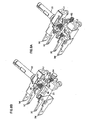
- Figure 8B illustrates an elevated perspective view of an actuator, carriage body, and contacts arranged in a stage 1 state.
- Figure 9A illustrates an elevated perspective view of select components of Figure 8B arranged in a stage 2 state.
- Figure 9B illustrates an elevated perspective view of the opposite side of the components shown in Figure 9A .
- Figure 10A illustrates an elevated perspective view of the select components of Figure 8B arranged in a stage 3 state.
- Figure 10B illustrates an elevated perspective view of the opposite side of the components shown in Figure 10A .
- Figure 11A illustrates an elevated perspective view of the components of Figure 8B arranged in a stage 4 state.
- Figure 11B illustrates an elevated perspective view of the opposite side of the components shown in Figure 11A .
- Figure 12A illustrates an elevated perspective view of the components of Figure 8B arranged in a stage 5 state.
- Figure 12B illustrates an elevated perspective view of the opposite side of the components shown in Figure 12A .
- Figure 13A illustrates an elevated perspective view of the components of Figure 8B arranged in a stage 6 state.
- Figure 13B illustrates an elevated perspective view of the opposite side of the components shown in Figure 13A .
- Figure 14A illustrates a partial perspective view of one embodiment of a switch including an exemplary embodiment of a lock device in an unlocked state, the switch being in a switch-deactuated position.
- Figure 14B illustrates a partial perspective view of the switch as shown in Figure 14A having the lock device in a "lock on” state and the switch in a switch-actuated position.
- Figure 14C illustrates a partial perspective view of the switch as shown in Figure 14A having the lock device in a "lock release” state and the switch not yet transited to a switch-deactuated position.
- Figure 14D illustrates a partial perspective view of another exemplary embodiment for a lock device for a switch having the lock device in a "lock off” state and the switch in a switch-deactuated position.
- Figure 14E illustrates a partial perspective view of the switch as shown in Figure 14D having the lock device in a lock-off state and the switch in a switch-activated position.
- Figure 15 illustrates a schematic of an exemplary embodiment of a wiring pattern for a switch in accordance with the principles of the present disclosure.
- Figure 16A illustrates a schematic of an exemplary embodiment of a single-pole, single-throw, non-teasable switch in accordance with the principles of the present disclosure.
- Figure 16B illustrates a schematic of multiple exemplary embodiments of single-pole, single-throw, non-teasable switches arranged in parallel in accordance with the principles of the present disclosure.
- Figure 17A illustrates a schematic of an exemplary embodiment of a double-pole, single-throw, non-teasable switch in accordance with the principles of the present disclosure.
- Figure 17B illustrates a schematic of multiple exemplary embodiments of double-pole, single-throw, non-teasable switches arranged in parallel in accordance with the principles of the present disclosure.
- Figure 18A illustrates a schematic of an exemplary embodiment of a single-pole, single-throw, non-teasable switch including a number of bus bars to drive a number of loads in accordance with the principles of the present disclosure.
- Figure 18B illustrates a schematic of an exemplary embodiment of a multiple-pole, single-throw, non-teasable switches including a number of bus bars to drive a number of loads in accordance with the principles of the present disclosure.
- embodiments of a switch are configured to minimize teasing between contacts in an electrical circuit.
- the switch In a switch-actuated position, the switch provides sufficient contact pressure between contacts to close the circuit. Conversely, in a switch-deactuated position, the switch removes all contact pressure between the contacts to open the circuit.
- the switch is described below in terms of an electrical wired circuit, this is exemplary only, and certain embodiments of the present invention may be suitable for use with other known circuit arrangements.
- FIGs 1A-1C illustrate exemplary embodiments of a switch 10 including a trigger 30, which is movable between a switch-actuated position and a switch-deactuated position.
- the trigger 30 includes a trigger insert 34 (best seen in Figure 3 ) that connects with an actuator 20 (best seen in Figure 2 ).
- the trigger 30 when activated ( e.g ., depressed), the trigger 30 pushes the actuator 20 toward the transfer carriage 40 (best shown in Figures 4 and 5 ) to move the switch 10 into the switch-actuated position.
- a first contact as seen in Fig. 4 , reference no. 12
- the first contact physically touches a second contact (as seen in Fig. 5 , reference no. 18).
- one or both of the first and second contacts include multiple contacts.
- the trigger 30 releases the actuator 20 and transfer carriage 40 when toggled into the switch-deactuated position.
- Moving the actuator 20 causes the first contact 12 to move into a released contact position, in which the first contact is separated from the second contact 18.
- the trigger 30 may be activated by any mechanical pressure, including pressure applied by an operator.
- the invention is not limited to mechanical pressure and the trigger 30 may also be activated by automated control.
- a switch 10 includes a housing 70 and cover 90 for protecting switch components.
- the housing 70 and cover 90 are arranged and configured to be coupled together such that the switch components are positioned within the volume created by the housing 70 and cover 90.
- One embodiment of the cover 90 is provided with side flanges 95 for connecting the cover 90 to the housing 70.
- one embodiment of the cover 90 includes a terminal block 92 and terminal frame 94 mounted thereon.
- the terminal block 92 and terminal frame 94 provide physical support for the second contacts 18 and include connecting terminals 2M, 2C and line input L2, which are discussed in further detail herein.
- sleeve 98 is provided at one end of the cover 90 to protect the actuator 20. The circuit will close when the first contacts 12 contact the second contacts 18, such that an electric current flows from terminal block 92 to the terminal frame 94 through the bridge plate 14. While the current flows through the bridge plate 14, current creepage may occur.
- Cover ribs 96 are provided on a surface of the cover 90 to decrease current creepage by increasing the distance through which the creepage would need to pass.
- the housing 70 includes line inputs. As shown, a first line input L1 and second line input L2 reside on a side of the housing 70 as input holes.
- the line inputs hole L1, L2 provide wire connection means for the switch to connect to a power source (not shown).
- Terminals 1M, 2C, 2M and 2C are disposed on the opposite side of the housing 70.
- First and second load side terminals 1M, 2M are provided on opposite sides of the cover 90. Additionally, first and second capacitor side terminals 1C, 2C are provided between the load side terminals 1M, 2M.
- the line input wire 1N and 2L may be respectively inserted into the line inputs hole L1 and L2 (shown in Figure 1C ) to connect a power source P to the switch.
- First and second load terminals 1M and 2M provide a connection to a motor (e.g., a power tool motor) for operating the motor.
- First and second capacitor side terminals 1C and 2C provide a connection to a capacitor X2 (e.g., an EMI filter).
- terminals 1M and 1C and input wire 1N are internally connected within the switch 10.
- the switch 10 is toggled on and off by connecting and separating terminals 2M and 2C with line input wire 2L.
- the round nodes SC on either end of the circuit denote the second contacts 18. These nodes SC come into or out of contact with first contact nodes FC via a contact bridge B (e.g., bridge plate 14 as shown in Figure 4 ).
- the contact between first contacts FC and second contacts SC connects terminal 2M with input wire 2L, thereby closing the circuit.
- the bridge B delivers the first contacts FC to the second contacts SC and connects terminal 2M with input wire 2L, thereby closing the circuit.
- the bridge B delivers the first contacts FC to the second contacts SC via movement of the transfer carriage 40 and the actuator 20 (as shown in Figure 2 ).
- one embodiment of the switch 10 includes a lock device 50 mounted on the housing 70.
- the lock device 50 provides a lock-on and a lock-off function to the trigger 30.
- the lock device 50 is further discussed herein with reference to Figures 14A-14E .
- Figures 2-4 show an exemplary embodiment of an actuator 20 and transfer carriage 40 of a transfer assembly 200.
- the actuator 20 includes a shaft 22.
- the shaft 22 is connected to a carriage container 24 at a first end, and includes interlocks 26 at a second, opposite end.
- the carriage container 24 is receivable of the transfer carriage 40.
- the transfer carriage 40 is slidable within the carriage container 24, such that actuator 20 and transfer carriage 40 move relative to one another.
- the transfer carriage 40 resembles a trolley-like structure that is movable linearly within the carriage container 24. More preferably, the carriage container 24 is substantially a boxed receptacle for housing the transfer carriage 40 therein.
- one embodiment of the actuator 20 may be connected to a trigger insert 34 for supporting the trigger 30.
- the actuator 20 is externally activated by a switch operator via the trigger 30.
- the trigger insert 34 may be securely connected to the actuator 20 by applying a fastener 35 (e.g., an e-ring), to lock the trigger insert 34 to the actuator 20.
- the fastener 35 is used to engage the interlocks 26 of the actuator 20.
- the trigger insert 34 provides ease of connection between the actuator 20 and the trigger 30, so that the actuator 20 may be comfortably activated and released by the switch operator.
- One side of the carriage container 24 includes first and second actuator cutouts 28, 29.
- the actuator cutouts 28, 29 are disposed as pairs on opposite sides of actuator 20, such that they extend in the longitudinal direction of shaft 22.
- the actuator cutouts 28, 29 will be discussed in further detail herein.
- the transfer carriage 40 includes a first set of carriage cutouts 49a and a second set of carriage cutouts 49b.
- the first set of carriage cutouts 49a are disposed on opposite ends of the transfer carriage 40 and extend transversely to the longitudinal direction of the shaft 22.
- the second set of carriage cutouts 49b are disposed on opposite sides of the transfer carriage 40 and extend in same direction as the first actuator cutouts 28, 29 and shaft 22.
- the first carriage cutouts 49a provide a space for first and second carriage plates 42a, 42b to slide therethrough.
- the shoulder portions of the transfer carriage 40 surrounding the first carriage cutouts 49a retain biasing surfaces 43a, 43b.
- the biasing surfaces 43a, 43b are biased outward by a first bias member 44a pushing against the biasing surfaces 43a, 43b.
- the first bias member 44a is illustrated as compressed against the second carriage plate 42b, which has been slid towards the first carriage plate 42a.
- the first carriage plate 42a could slide towards the second carriage plate 42b, thereby compressing the first bias 44a against the first carriage plate 42a in a similar manner.
- the first bias 44a is a spring.
- the bridge plate 14 is slidingly engaged with the transfer carriage 40 along the second carriage cutouts 49b.
- the bridge plate 14 includes the first contacts 12 disposed on either end of the bridge plate 14.
- the first contacts 12 face towards the second contacts 18, which are located on one end of the transfer carriage 40.
- the bridge plate includes grooves (best shown in Figure 6 ).
- a second carriage biasing member 44b biases the bridge plate 14 toward the second contacts 18.
- the bridge plate 14 slides along the second carriage cutouts 49b and along the first actuator cutouts 28 to deliver the first contacts 12 into and out of contact with the second contacts 18.
- the second contacts 18 are fixed on the terminal frame 94 and terminal block 92 as shown in Figures 5 and 6 .
- the bridge plate 14 is moved towards and away from the second contacts 18 so as to connect and separate the first and second contacts 12, 18.
- the first contacts 12 are arranged as a first and second contact pad that come into and out of contact with a corresponding pair of contact pads for the second contacts 18.
- the bridge plate 14 connects the pads in order to close the circuit.
- the bridge plate 14 also include magnets 16 disposed on the opposite side of the bridge plate 14 from which the contact pads of the first contacts 12 are located. In this kind of configuration, the bridge plate is pulled towards the second contact 18 to provide sufficient contact pressure on the contacts 12, 18.
- a potential difference exists between the terminal block 92 and the terminal frame 94.
- the magnets 16 and the terminal block and frame 92, 94 may have a difference in magnet polarity.
- either the magnets 16 or terminal block and frame 92, 94 can have a magnetic field and the other can be composed of iron.
- the transfer carriage 40 snaps on and off in a short period of time to close and break the circuit.
- one embodiment of the transfer carriage 40 includes at least one cam member 48.
- Another embodiment of the transfer carriage 40 includes cam member 48 oppositely disposed on either side of the transfer carriage 40, opposite the second carriage cutouts 49b.
- the cam members 48 move in the same longitudinal direction as the actuator 20 when the trigger 30 is activated to move the actuator 20 and the transfer carriage 40.
- a transfer barrier prevents the transfer carriage 40 from moving towards the second contacts 18 unless sufficient force is applied to the actuator 20 and transfer carriage 40 to overcome the transfer barrier.
- the transfer barrier includes an assembly of cam balls 60 biased toward the transfer carriage 40 by ball biasing members 62.
- the cam balls 60 and ball biasing members 62 are supported by ball stops 64.
- ball stops 64 are insertable into the housing 70 at holes 75.
- the ball stops 64 include a waved contour so that they are self-locked in the housing holes 75 via an interference fit
- the cam balls 60 are steel balls that lock the cam members 48 so as to prevent movement of the transfer carriage 40 even when the actuator 20 is initially moved.
- the transfer assembly 200 which includes the actuator 20, the transfer carriage 40, and a flip-flop mechanism, operates in cooperation with the transfer barrier.
- the flip-flop mechanism preferably includes the first and second carriage plates 42a, 42b operating in cooperation with the first biasing member 44a.
- the flip-flop mechanism further includes the bridge plate 14 and second biasing member 44b.
- the cam members 48 of the transfer carriage 40 cooperate with the transfer barrier to prevent movement of the transfer carriage 40.
- the transfer barrier includes the cam balls 60, ball biasing members 62, and ball stoppers 64.
- Figure 8A illustrates the switch 10 having the transfer assembly arranged in a switch-deactuated position.
- Figure 8B illustrates the transfer assembly of the switch 10 including the actuator 20, transfer carriage 40, a flip-flop mechanism, and contacts 12, 18 arranged in the switch-deactuated position.
- a switch operator activates the actuator 20 via the trigger 30, which causes the transfer carriage 40 to move relative to the actuator 20.
- the actuator 20 is moved to initiate delivery of the transfer carriage 40 and first contact 12 toward the second contact 18.
- a transfer barrier prevents movement of the carriage 40 by providing an energy barrier. Preventing movement of the carriage 40 while moving the actuator 20 causes transfer energy to build up in the flip-flop mechanism.
- the transfer carriage 40 is locked from movement until a sufficient amount of energy is input into the system. When a sufficient amount of energy is provided via the trigger 30, the transfer carriage 40 overcomes the transfer barrier. When the transfer barrier is overcome, the flip-flop mechanism changes states, thereby moving the carriage 40 towards the second contacts 18.
- the switch 10 now is in the switch-actuated position and a transfer barrier prevents movement back to the switch-deactuated position.
- FIGS 8A-14B various stages of select components within the switch 10 are illustrated describing toggling of the switch 10 between switch-actuated and switch-deactuated positions.
- Figures 8A and 8B illustrate components of the switch 10 arranged in a stage 1 "release state.”
- Figures 9A-9B illustrate the select components shown in Figure 8B arranged in a stage 2 "first energy build up” state in which the actuator 20 is moved further towards the second contacts 18.
- the actuator 20 presses against the transfer carriage 40 to move the cam members 48 up to the cam balls 60 of the transfer barrier, such that the transfer carriage 40 is at a transfer point.
- the first biasing member 44a is compressed, thereby creating and storing transfer energy in the first carriage biasing member 44a at the transfer point.
- Figures 10A-10B illustrate the select components of Figure 8B arranged in a stage 3 "fly to on" state. If further pressure is applied to the actuator 20, the transfer carriage 40 will overcome the transfer barrier and be free to move past the transfer point. In particular, the energy built up from the compression of the first biasing member 44a enables the cam members 48 of the transfer carriage 40 to overcome the resistance of the cam balls 60. The cam members 48 are allowed to move as a result of the space created by the second actuator cutouts 29. Thus, there is no force to resist movement of the transfer carriage 40, towards the second contact 18. At this point, the cam members 48 quickly slide (i.e., or fly) over the cam balls 60. Thus, the cam balls 60 retract away from the transfer carriage 40 by compression of the ball biasing members 62 toward the ball stops 64.
- Figures 11A-11B illustrate the select components of Figure 8B arranged in a stage 4 "switch on" state.
- Figures 12A-12B illustrate the select components of Figure 8B arranged in a stage 5 "second energy pile up" state.
- the transfer barrier retains the transfer carriage 40 in the "switch on” state such that contact between the first and second contacts 12, 18 is maintained.
- the actuator 20 must now be moved in a direction away from the second contacts 18 in order to toggle the switch to the switch-deactuated position.
- the first biasing member 44a is then compressed in a manner similar to stage 2, but from the opposite side.
- Second carriage plate 42b is slid through first carriage cutout 49a, such that the second biasing surface 43b compresses the first biasing member 44a against the first biasing surface 43a of the first carriage plate 42a.
- a second transfer energy is stored at a second transfer point where the cam members 48 are pushed against the cam balls 60 from the opposite side.
- This energy storage configuration is analogous to the first energy storage configuration of stage 2 illustrated in Figures 9A-9B .
- Figures 13A-13B illustrate the select components of Figure 8B arranged in a stage 6 "fly to off' state.
- the transfer carriage 40 is pulled away from the second contacts 18 with sufficient force to overcome the cam balls 60.
- the cam members 48 slide quickly over the cam balls 60, thereby releasing the second transfer energy stored in stage 5.
- the release causes the bridge plate 14 to quickly separate from the second contacts 18.
- This configuration is analogous to the "fly to on" state of stage 3 illustrated in Figures 10A-10B , except that the transfer carriage 40 and bridge plate 14 are moving in the opposite direction.
- the select components of the switch 10 return to the stage 1 "release" state.
- one switch-actuated/switch-deactuated position cycle is completed.
- biasing members 44a, 44b, 62 described may be any biasing member that is equally suitable for the desired application, are not limited to the coil springs as shown.
- other arrangements for the switch components may vary as necessary to suit any desired application.
- a locking device 50 maintains the transfer carriage 40 in the closed circuit position (i.e., or "switch on” state) or maintains the transfer carriage 40 in the "release” position.
- Figures 15A-15E illustrate partial perspective views of the lock device 50 of the switch 10. Relevant components are shown for purposes of illustration. It is emphasized that the lock device 50 shown in Figures 14A-14E is exemplary only as other arrangements may be equally suitable.
- Figures 14A-14C illustrate the lock device 50 respectively in the "lock off, switch off” state, the "lock on, switch on” state, and the “lock off, switch on” state.
- the lock device 50 includes a lock button 51.
- the lock button 51 includes a fastener 51a that connects to a reciprocating member 51b.
- the reciprocating member 51b is movable into and out of the housing 70.
- a lock biasing member 54 is disposed within the lock button 51.
- the lock biasing member 54 is disposed annularly about the fastener member 51a and reciprocating member 51b.
- the lock button 51 is connected to the housing 70 through an annular collar 59.
- the lock button 51 and collar 59 provide a biasing space 56 therebetween, such that the lock button 51 may move into and out of the annular collar 56.
- a reciprocating space 55 is provided within the housing 70, such that the reciprocating member 51b may reciprocate into and out of the housing 70.
- the lock button 51 connects with a lock device lever 52 to engage a catch member 58.
- the lever 52 is shown released from the catch member 58 in a "lock off, switch off” position.
- the lever 52 is shown engaged with the catch member 58 in a "lock on, switch on” position.
- Figure 14C illustrates the lever 52 released from the catch member 58 in a "lock off, switch on” position.
- Figures 14D-14E illustrate an alternative embodiment for the lock device 50.
- a lock device shoulder 38 may be employed such that the switch 10 is locked in a switch-deactuated position and released in a switch-actuated position.
- Figure 14D shows the lock device 50 in a "lock on, switch-deactuated” stage.
- Figure 14E shows the lock device 50 in a "lock off, switch-actuated” stage.
- lock device 50 may be preferable for switch operation, it may not be necessary in all embodiments.
- Figures 16 (A-B) - 19(A-B) illustrate multiple schematic arrangements for using a non-teasable switch 100.
- Figure 16A illustrates one embodiment of a switch 100 as a single-pole, single-throw, non-teasable switch. This configuration is analogous to the wiring pattern having a motor shown in Figure 15 .
- Figure 16B illustrates a schematic for multiple single-pole, single-throw, non-teasable switches 100 arranged in parallel.
- Figure 17A illustrates an embodiment of a non-teasable switch 101 arranged in a double-pole, single-throw, non-teasable switch 101 configuration.
- Figure 17B illustrates multiple double-pole, single-throw, non-teasable switches 101 arranged in parallel.
- Figure 18A illustrates a single-pole, single-throw, non-teasable switch 103 and further including a number of bus bars 102 to drive a number of loads.
- Figure 18B illustrates multiple-pole, single-throw, non-teasable switches 103 including a number of bus bars to drive a number of loads.
- the switch as herein described prevents teasing that may occur between contacts in a circuit, thereby preventing arcing and sparking. Welding of contacts may also be avoided when using this switch.
- the switch is incorporated in a trigger for a hand operated power tool. It is emphasized that this application is exemplary only. The switch is not limited only to use with electrical circuits as described. It may also be adaptable for use with other known on/off circuits for preventing teasing. The non-teasable switch is also not limited only to the uses described herein. Other arrangements that produce similar functionality may be equally suitable.
- various embodiments of the switch may be adapted for use with various currents and voltages, and either AC or DC power.
- the present invention is not limited exclusively to electrical circuit interruption.
- the switch is not limited only to the particular arrangement of electrical circuits shown and described herein.
- Embodiments of the present invention may be suitable for use with circuits operating at a variety of AC and DC voltages, and/or a variety of AC and DC currents.
- switch is described herein in terms of a device that is integrated into an electrical circuit, this is exemplary only. Certain embodiments of the present invention may be suitable for partial or total integration into larger circuits, appliances, or other devices. However, other embodiments of the present invention may be suitable for use as modules used with other circuits or devices.
Claims (9)
- Interrupteur sans accrochage (10), comprenant :un premier contact (12) pouvant être déplacé vers un deuxième contact (18) à partir d'une position de désactivation de l'interrupteur vers une position d'activation de l'interrupteur, et pouvant être déplacé à l'écart dudit deuxième contact (18), de ladite position d'activation de l'interrupteur pour retourner dans ladite position de désactivation de l'interrupteur, ledit premier contact (12) contactant de manière amovible ledit deuxième contact (18) dans ladite position d'activation de l'interrupteur et ledit premier contact (12) étant séparé dudit deuxième contact (18) dans ladite position de désactivation de l'interrupteur ;un chariot de transfert (40), engagé en service dans ledit premier contact (12) et pouvant être déplacé vers ledit deuxième contact (18) et à l'écart de celui-ci, entre lesdites positions de désactivation et d'activation de l'interrupteur, ledit chariot de transfert (40) étant agencé et configuré de sorte à recevoir un mécanisme à bascule pour établir un contact entre ledit premier contact (12) et ledit deuxième contact (18) et pour dégager ledit premier contact (12) dudit deuxième contact (18) ; ledit mécanisme à bascule surmontant une barrière de transfert entre lesdites positions d'activation et de désactivation de l'interrupteur ; etun actionneur (20), engagé en service dans ledit chariot de transfert (40) et pouvant être déplacé vers ledit deuxième contact (18) et à l'écart de celui-ci, ledit actionneur (20) pouvant être déplacé pour entraîner un déplacement dudit chariot de transfert (40) et dudit premier contact (12) entre lesdites positions de désactivation et d'activation de l'interrupteur, et ledit actionneur (20) pouvant être déplacé pour entraîner un déplacement dudit chariot de transfert (40) afin de surmonter ladite barrière de transfert à partir desdites deux positions de désactivation et d'activation de l'interrupteur ;dans lequel ledit premier contact (12) est transféré en vue d'une mise en contact avec ledit deuxième contact (18) et d'un dégagement de celui-ci par l'intermédiaire dudit actionneur (20) et dudit chariot de transfert (40) ;dans lequel ledit mécanisme à bascule englobe une plaque de pontage (14), coopérant avec des deuxièmes entailles du chariot (49b) et un deuxième élément poussoir (44b), pour pousser ladite plaque de pontage (14) vers ledit deuxième contact (18), ladite plaque de pontage (14) englobant ledit premier contact (12) qui y est connecté, ladite plaque de pontage (14) étant ainsi poussée de sorte à établir un contact entre lesdits premier et deuxième contacts (12, 18) ;caractérisé en ce que l'interrupteur sans accrochage comprend un dispositif de verrouillage (50), ledit dispositif de verrouillage (50) étant configuré et agencé de sorte que lors de l'actionnement dudit dispositif de verrouillage (50), il retient ledit actionneur (20) et ledit chariot de transfert (40) dans ladite position d'activation de l'interrupteur ou dans ladite position de désactivation de l'interrupteur ;et en ce que le mécanisme à bascule englobe en outre des première et deuxième plaques de chariot (42a, 42b), coopérant avec des premières entailles du chariot (49a) et un premier élément poussoir (44a), ledit mécanisme à bascule coopérant avec ledit actionneur (20) pour déplacer ledit chariot de transfert (40) dans ledit actionneur (20) par rapport au déplacement dudit actionneur (20).
- Interrupteur sans accrochage selon la revendication 1, comprenant en outre un boîtier (70) et un couvercle (90) pour contenir et protéger ledit interrupteur (10).
- Interrupteur sans accrochage selon la revendication 1, comprenant en outre au moins un connecteur de borne et au moins une entrée de ligne (L1, L2), ledit connecteur de borne pouvant être connecté à au moins une charge électrique ou un composant passif (composant non consommateur d'énergie), ladite entrée de ligne pouvant recevoir des connecteurs pour connecter ledit interrupteur à une source d'énergie (P).
- Interrupteur sans accrochage selon la revendication 1, comprenant en outre un déclencheur (30), ledit déclencheur (30) étant construit et agencé de sorte à activer et à relâcher ledit actionneur (20) et ledit chariot de transfert (40) dans ladite position d'activation de l'interrupteur et ladite position de désactivation de l'interrupteur.
- Interrupteur sans accrochage selon la revendication 1, dans lequel ledit actionneur (20) et ledit chariot de transfert (40) se déplacent l'un par rapport à l'autre.
- Interrupteur sans accrochage selon la revendication 1, dans lequel ledit actionneur (20) englobe un arbre (22) et un conteneur du chariot (24) agencé au niveau d'une extrémité dudit arbre (22), ledit conteneur du chariot (24) contenant ledit chariot de transfert (40), ledit conteneur du chariot (24) englobant des entailles (28, 29), pour permettre le déplacement dudit chariot de transfert (40) dans ledit conteneur du chariot (24).
- Interrupteur sans accrochage selon la revendication 1, dans lequel ledit premier contact (12) englobe deux doigts de contact.
- Interrupteur sans accrochage selon la revendication 1, dans lequel ledit chariot de transfert (40) englobe au moins un élément de came (48), destiné à coopérer avec ladite barrière de transfert, ledit élément de came (40) pouvant être déplacé vers un côté de ladite barrière de transfert dans un premier stade de transfert de l'énergie accumulée lorsque ledit chariot de transfert (40) et l'actionneur (20) sont déplacés vers une position d'activation de l'interrupteur, ledit élément de came (40) pouvant être déplacé vers un autre côté de ladite barrière de transfert dans un deuxième stade de transfert de l'énergie accumulée lorsque ledit chariot de transfert (40) et ledit actionneur (20) sont déplacés vers une position de désactivation de l'interrupteur.
- Interrupteur sans accrochage selon la revendication 8, dans lequel ladite barrière de transfert englobe au moins une bille à came (60), au moins un élément poussoir de la bille (62) et au moins un arrêt de la bille (64), une extrémité de l'élément poussoir de la bille (62) étant accouplée à l'arrêt de la bille (64) et l'autre extrémité de l'élément poussoir de la bille (62) étant accouplée à la bille à came (60), ledit élément poussoir de la bille (62) poussant ladite bille à came (60) vers ledit chariot de transfert (40) et opposant une résistance au déplacement dudit chariot de transfert (40) par l'intermédiaire dudit élément de came (48).
Priority Applications (1)
| Application Number | Priority Date | Filing Date | Title |
|---|---|---|---|
| EP06256509.8A EP1936645B1 (fr) | 2006-12-21 | 2006-12-21 | Interrupteur pour produire une connexion et une interruption brusques des contacts électriques |
Applications Claiming Priority (1)
| Application Number | Priority Date | Filing Date | Title |
|---|---|---|---|
| EP06256509.8A EP1936645B1 (fr) | 2006-12-21 | 2006-12-21 | Interrupteur pour produire une connexion et une interruption brusques des contacts électriques |
Publications (2)
| Publication Number | Publication Date |
|---|---|
| EP1936645A1 EP1936645A1 (fr) | 2008-06-25 |
| EP1936645B1 true EP1936645B1 (fr) | 2013-07-03 |
Family
ID=38045585
Family Applications (1)
| Application Number | Title | Priority Date | Filing Date |
|---|---|---|---|
| EP06256509.8A Active EP1936645B1 (fr) | 2006-12-21 | 2006-12-21 | Interrupteur pour produire une connexion et une interruption brusques des contacts électriques |
Country Status (1)
| Country | Link |
|---|---|
| EP (1) | EP1936645B1 (fr) |
Families Citing this family (3)
| Publication number | Priority date | Publication date | Assignee | Title |
|---|---|---|---|---|
| EP3101671B1 (fr) | 2015-06-04 | 2019-02-20 | Satori Electric Co., Ltd. | Interrupteur |
| JP6720901B2 (ja) | 2017-03-14 | 2020-07-08 | オムロン株式会社 | トリガースイッチ |
| EP3926653A1 (fr) * | 2020-06-15 | 2021-12-22 | ABB Power Grids Switzerland AG | Système de réduction de rebond de contact |
Citations (1)
| Publication number | Priority date | Publication date | Assignee | Title |
|---|---|---|---|---|
| EP0702381A1 (fr) * | 1994-09-16 | 1996-03-20 | Heinrich Kopp Ag | Dispositif de sécurité mécanique agissant sur la commutation d'un bouton-poussoir électrique |
Family Cites Families (5)
| Publication number | Priority date | Publication date | Assignee | Title |
|---|---|---|---|---|
| US2347874A (en) | 1942-09-07 | 1944-05-02 | Gen Motors Corp | Electric switch |
| US4154996A (en) | 1977-05-12 | 1979-05-15 | Mcgraw-Edison Company | Positive break snap action switch |
| DE19930558A1 (de) | 1998-07-24 | 2000-01-27 | Marquardt Gmbh | Elektrischer Schalter |
| DE10034670A1 (de) | 2000-07-17 | 2002-01-31 | Kopp Heinrich Ag | Vorrichtung zur mechanischen Sicherung der EIN- und AUS-Schaltstellung eines elektrischen Druckschalters |
| DE10217406B4 (de) | 2001-04-19 | 2014-05-15 | Marquardt Gmbh | Elektrischer Schalter |
-
2006
- 2006-12-21 EP EP06256509.8A patent/EP1936645B1/fr active Active
Patent Citations (1)
| Publication number | Priority date | Publication date | Assignee | Title |
|---|---|---|---|---|
| EP0702381A1 (fr) * | 1994-09-16 | 1996-03-20 | Heinrich Kopp Ag | Dispositif de sécurité mécanique agissant sur la commutation d'un bouton-poussoir électrique |
Also Published As
| Publication number | Publication date |
|---|---|
| EP1936645A1 (fr) | 2008-06-25 |
Similar Documents
| Publication | Publication Date | Title |
|---|---|---|
| US7211758B2 (en) | Circuit interrupter that produces snap-action connection and disconnection between electrical contacts | |
| CN1092392C (zh) | 电磁开关装置 | |
| US6864769B2 (en) | Lockout mechanism for residual current devices | |
| JP3930283B2 (ja) | トグル機構を備えた電源切替開閉器 | |
| EP1936645B1 (fr) | Interrupteur pour produire une connexion et une interruption brusques des contacts électriques | |
| CN108364835B (zh) | 高电压直流继电器 | |
| DE19930558A1 (de) | Elektrischer Schalter | |
| CN102870185B (zh) | 电气开关装置及其状态指示组件 | |
| KR102374581B1 (ko) | 수동 액츄에이터를 구비한 고전압 래칭 릴레이 | |
| CN109509653B (zh) | 开关装置和相关联的开关 | |
| EP0720771B1 (fr) | Dispositif de commutateur | |
| CN101840807B (zh) | 电气安装设备的开关模块 | |
| CN107958806A (zh) | 用于闩锁的装置与方法以及包括该闩锁装置的系统 | |
| US3908473A (en) | Linear motion snap-action mechanism | |
| CN108878185B (zh) | 两段位自动转换开关电器 | |
| CN201788864U (zh) | 具有经由耦合装置彼此连接的两个触点装置的开关 | |
| CN212848145U (zh) | 带自锁功能的手柄按压开关 | |
| CN217934478U (zh) | 连接器组件 | |
| CN219643427U (zh) | 联锁机构和低压柜抽屉 | |
| KR100584826B1 (ko) | 고압기기의 트리거장치 | |
| JPS645791Y2 (fr) | ||
| CN117542708A (zh) | 一种接地故障断路器 | |
| JP2023004202A (ja) | スイッチ装置 | |
| KR100486749B1 (ko) | 3상 분리형 개폐기의 수동트립장치 | |
| CN105027251A (zh) | 触点装置以及电路断路器 |
Legal Events
| Date | Code | Title | Description |
|---|---|---|---|
| PUAI | Public reference made under article 153(3) epc to a published international application that has entered the european phase |
Free format text: ORIGINAL CODE: 0009012 |
|
| AK | Designated contracting states |
Kind code of ref document: A1 Designated state(s): AT BE BG CH CY CZ DE DK EE ES FI FR GB GR HU IE IS IT LI LT LU LV MC NL PL PT RO SE SI SK TR |
|
| AX | Request for extension of the european patent |
Extension state: AL BA HR MK RS |
|
| 17P | Request for examination filed |
Effective date: 20081112 |
|
| 17Q | First examination report despatched |
Effective date: 20081219 |
|
| AKX | Designation fees paid |
Designated state(s): AT BE BG CH CY CZ DE DK EE ES FI FR GB GR HU IE IS IT LI LT LU LV MC NL PL PT RO SE SI SK TR |
|
| GRAP | Despatch of communication of intention to grant a patent |
Free format text: ORIGINAL CODE: EPIDOSNIGR1 |
|
| RIN1 | Information on inventor provided before grant (corrected) |
Inventor name: LUI, NELSON MAN HOI |
|
| GRAS | Grant fee paid |
Free format text: ORIGINAL CODE: EPIDOSNIGR3 |
|
| GRAA | (expected) grant |
Free format text: ORIGINAL CODE: 0009210 |
|
| AK | Designated contracting states |
Kind code of ref document: B1 Designated state(s): AT BE BG CH CY CZ DE DK EE ES FI FR GB GR HU IE IS IT LI LT LU LV MC NL PL PT RO SE SI SK TR |
|
| REG | Reference to a national code |
Ref country code: GB Ref legal event code: FG4D |
|
| REG | Reference to a national code |
Ref country code: CH Ref legal event code: EP Ref country code: AT Ref legal event code: REF Ref document number: 620179 Country of ref document: AT Kind code of ref document: T Effective date: 20130715 |
|
| REG | Reference to a national code |
Ref country code: IE Ref legal event code: FG4D |
|
| REG | Reference to a national code |
Ref country code: CH Ref legal event code: NV Representative=s name: MARKS AND CLERK (LUXEMBOURG) LLP, CH |
|
| REG | Reference to a national code |
Ref country code: DE Ref legal event code: R096 Ref document number: 602006037081 Country of ref document: DE Effective date: 20130829 |
|
| PG25 | Lapsed in a contracting state [announced via postgrant information from national office to epo] |
Ref country code: SI Free format text: LAPSE BECAUSE OF FAILURE TO SUBMIT A TRANSLATION OF THE DESCRIPTION OR TO PAY THE FEE WITHIN THE PRESCRIBED TIME-LIMIT Effective date: 20130703 |
|
| REG | Reference to a national code |
Ref country code: AT Ref legal event code: MK05 Ref document number: 620179 Country of ref document: AT Kind code of ref document: T Effective date: 20130703 |
|
| REG | Reference to a national code |
Ref country code: NL Ref legal event code: VDEP Effective date: 20130703 |
|
| REG | Reference to a national code |
Ref country code: LT Ref legal event code: MG4D |
|
| PG25 | Lapsed in a contracting state [announced via postgrant information from national office to epo] |
Ref country code: SE Free format text: LAPSE BECAUSE OF FAILURE TO SUBMIT A TRANSLATION OF THE DESCRIPTION OR TO PAY THE FEE WITHIN THE PRESCRIBED TIME-LIMIT Effective date: 20130703 Ref country code: PT Free format text: LAPSE BECAUSE OF FAILURE TO SUBMIT A TRANSLATION OF THE DESCRIPTION OR TO PAY THE FEE WITHIN THE PRESCRIBED TIME-LIMIT Effective date: 20131104 Ref country code: IS Free format text: LAPSE BECAUSE OF FAILURE TO SUBMIT A TRANSLATION OF THE DESCRIPTION OR TO PAY THE FEE WITHIN THE PRESCRIBED TIME-LIMIT Effective date: 20131103 Ref country code: CY Free format text: LAPSE BECAUSE OF FAILURE TO SUBMIT A TRANSLATION OF THE DESCRIPTION OR TO PAY THE FEE WITHIN THE PRESCRIBED TIME-LIMIT Effective date: 20130724 Ref country code: LT Free format text: LAPSE BECAUSE OF FAILURE TO SUBMIT A TRANSLATION OF THE DESCRIPTION OR TO PAY THE FEE WITHIN THE PRESCRIBED TIME-LIMIT Effective date: 20130703 Ref country code: AT Free format text: LAPSE BECAUSE OF FAILURE TO SUBMIT A TRANSLATION OF THE DESCRIPTION OR TO PAY THE FEE WITHIN THE PRESCRIBED TIME-LIMIT Effective date: 20130703 Ref country code: BE Free format text: LAPSE BECAUSE OF FAILURE TO SUBMIT A TRANSLATION OF THE DESCRIPTION OR TO PAY THE FEE WITHIN THE PRESCRIBED TIME-LIMIT Effective date: 20130703 |
|
| PG25 | Lapsed in a contracting state [announced via postgrant information from national office to epo] |
Ref country code: LV Free format text: LAPSE BECAUSE OF FAILURE TO SUBMIT A TRANSLATION OF THE DESCRIPTION OR TO PAY THE FEE WITHIN THE PRESCRIBED TIME-LIMIT Effective date: 20130703 Ref country code: GR Free format text: LAPSE BECAUSE OF FAILURE TO SUBMIT A TRANSLATION OF THE DESCRIPTION OR TO PAY THE FEE WITHIN THE PRESCRIBED TIME-LIMIT Effective date: 20131004 Ref country code: NL Free format text: LAPSE BECAUSE OF FAILURE TO SUBMIT A TRANSLATION OF THE DESCRIPTION OR TO PAY THE FEE WITHIN THE PRESCRIBED TIME-LIMIT Effective date: 20130703 Ref country code: PL Free format text: LAPSE BECAUSE OF FAILURE TO SUBMIT A TRANSLATION OF THE DESCRIPTION OR TO PAY THE FEE WITHIN THE PRESCRIBED TIME-LIMIT Effective date: 20130703 Ref country code: FI Free format text: LAPSE BECAUSE OF FAILURE TO SUBMIT A TRANSLATION OF THE DESCRIPTION OR TO PAY THE FEE WITHIN THE PRESCRIBED TIME-LIMIT Effective date: 20130703 Ref country code: ES Free format text: LAPSE BECAUSE OF FAILURE TO SUBMIT A TRANSLATION OF THE DESCRIPTION OR TO PAY THE FEE WITHIN THE PRESCRIBED TIME-LIMIT Effective date: 20131014 |
|
| PG25 | Lapsed in a contracting state [announced via postgrant information from national office to epo] |
Ref country code: CY Free format text: LAPSE BECAUSE OF FAILURE TO SUBMIT A TRANSLATION OF THE DESCRIPTION OR TO PAY THE FEE WITHIN THE PRESCRIBED TIME-LIMIT Effective date: 20130703 |
|
| PG25 | Lapsed in a contracting state [announced via postgrant information from national office to epo] |
Ref country code: SK Free format text: LAPSE BECAUSE OF FAILURE TO SUBMIT A TRANSLATION OF THE DESCRIPTION OR TO PAY THE FEE WITHIN THE PRESCRIBED TIME-LIMIT Effective date: 20130703 Ref country code: EE Free format text: LAPSE BECAUSE OF FAILURE TO SUBMIT A TRANSLATION OF THE DESCRIPTION OR TO PAY THE FEE WITHIN THE PRESCRIBED TIME-LIMIT Effective date: 20130703 Ref country code: CZ Free format text: LAPSE BECAUSE OF FAILURE TO SUBMIT A TRANSLATION OF THE DESCRIPTION OR TO PAY THE FEE WITHIN THE PRESCRIBED TIME-LIMIT Effective date: 20130703 Ref country code: DK Free format text: LAPSE BECAUSE OF FAILURE TO SUBMIT A TRANSLATION OF THE DESCRIPTION OR TO PAY THE FEE WITHIN THE PRESCRIBED TIME-LIMIT Effective date: 20130703 Ref country code: RO Free format text: LAPSE BECAUSE OF FAILURE TO SUBMIT A TRANSLATION OF THE DESCRIPTION OR TO PAY THE FEE WITHIN THE PRESCRIBED TIME-LIMIT Effective date: 20130703 |
|
| PLBE | No opposition filed within time limit |
Free format text: ORIGINAL CODE: 0009261 |
|
| STAA | Information on the status of an ep patent application or granted ep patent |
Free format text: STATUS: NO OPPOSITION FILED WITHIN TIME LIMIT |
|
| 26N | No opposition filed |
Effective date: 20140404 |
|
| REG | Reference to a national code |
Ref country code: DE Ref legal event code: R097 Ref document number: 602006037081 Country of ref document: DE Effective date: 20140404 |
|
| PG25 | Lapsed in a contracting state [announced via postgrant information from national office to epo] |
Ref country code: TR Free format text: LAPSE BECAUSE OF FAILURE TO SUBMIT A TRANSLATION OF THE DESCRIPTION OR TO PAY THE FEE WITHIN THE PRESCRIBED TIME-LIMIT Effective date: 20130703 |
|
| PG25 | Lapsed in a contracting state [announced via postgrant information from national office to epo] |
Ref country code: HU Free format text: LAPSE BECAUSE OF FAILURE TO SUBMIT A TRANSLATION OF THE DESCRIPTION OR TO PAY THE FEE WITHIN THE PRESCRIBED TIME-LIMIT; INVALID AB INITIO Effective date: 20061221 Ref country code: BG Free format text: LAPSE BECAUSE OF FAILURE TO SUBMIT A TRANSLATION OF THE DESCRIPTION OR TO PAY THE FEE WITHIN THE PRESCRIBED TIME-LIMIT Effective date: 20130703 |
|
| REG | Reference to a national code |
Ref country code: FR Ref legal event code: PLFP Year of fee payment: 10 |
|
| PGFP | Annual fee paid to national office [announced via postgrant information from national office to epo] |
Ref country code: IE Payment date: 20151209 Year of fee payment: 10 |
|
| PGFP | Annual fee paid to national office [announced via postgrant information from national office to epo] |
Ref country code: MC Payment date: 20151028 Year of fee payment: 10 |
|
| REG | Reference to a national code |
Ref country code: FR Ref legal event code: PLFP Year of fee payment: 11 |
|
| PG25 | Lapsed in a contracting state [announced via postgrant information from national office to epo] |
Ref country code: MC Free format text: LAPSE BECAUSE OF NON-PAYMENT OF DUE FEES Effective date: 20170102 |
|
| REG | Reference to a national code |
Ref country code: IE Ref legal event code: MM4A |
|
| PG25 | Lapsed in a contracting state [announced via postgrant information from national office to epo] |
Ref country code: IE Free format text: LAPSE BECAUSE OF NON-PAYMENT OF DUE FEES Effective date: 20161221 |
|
| REG | Reference to a national code |
Ref country code: FR Ref legal event code: PLFP Year of fee payment: 12 |
|
| PGFP | Annual fee paid to national office [announced via postgrant information from national office to epo] |
Ref country code: LU Payment date: 20191219 Year of fee payment: 14 |
|
| PG25 | Lapsed in a contracting state [announced via postgrant information from national office to epo] |
Ref country code: LU Free format text: LAPSE BECAUSE OF NON-PAYMENT OF DUE FEES Effective date: 20201221 |
|
| PGFP | Annual fee paid to national office [announced via postgrant information from national office to epo] |
Ref country code: CH Payment date: 20230103 Year of fee payment: 17 |
|
| PGFP | Annual fee paid to national office [announced via postgrant information from national office to epo] |
Ref country code: GB Payment date: 20231220 Year of fee payment: 18 |
|
| PGFP | Annual fee paid to national office [announced via postgrant information from national office to epo] |
Ref country code: IT Payment date: 20231228 Year of fee payment: 18 Ref country code: FR Payment date: 20231221 Year of fee payment: 18 Ref country code: DE Payment date: 20231214 Year of fee payment: 18 |
|
| PGFP | Annual fee paid to national office [announced via postgrant information from national office to epo] |
Ref country code: CH Payment date: 20240102 Year of fee payment: 18 |