EP1936645B1 - Circuit interrupter that produces snap-action connection and disconnection between electrical contacts - Google Patents
Circuit interrupter that produces snap-action connection and disconnection between electrical contacts Download PDFInfo
- Publication number
- EP1936645B1 EP1936645B1 EP06256509.8A EP06256509A EP1936645B1 EP 1936645 B1 EP1936645 B1 EP 1936645B1 EP 06256509 A EP06256509 A EP 06256509A EP 1936645 B1 EP1936645 B1 EP 1936645B1
- Authority
- EP
- European Patent Office
- Prior art keywords
- switch
- contact
- carriage
- transfer
- actuator
- Prior art date
- Legal status (The legal status is an assumption and is not a legal conclusion. Google has not performed a legal analysis and makes no representation as to the accuracy of the status listed.)
- Active
Links
- 230000004888 barrier function Effects 0.000 claims description 23
- 238000004146 energy storage Methods 0.000 claims description 4
- 239000003990 capacitor Substances 0.000 description 3
- 230000006835 compression Effects 0.000 description 3
- 238000007906 compression Methods 0.000 description 3
- 230000000994 depressogenic effect Effects 0.000 description 3
- 238000003466 welding Methods 0.000 description 3
- XEEYBQQBJWHFJM-UHFFFAOYSA-N Iron Chemical compound [Fe] XEEYBQQBJWHFJM-UHFFFAOYSA-N 0.000 description 2
- 238000010276 construction Methods 0.000 description 2
- 238000010413 gardening Methods 0.000 description 2
- 229910000831 Steel Inorganic materials 0.000 description 1
- 230000010354 integration Effects 0.000 description 1
- 229910052742 iron Inorganic materials 0.000 description 1
- 238000004519 manufacturing process Methods 0.000 description 1
- 239000000463 material Substances 0.000 description 1
- 238000000034 method Methods 0.000 description 1
- 239000000203 mixture Substances 0.000 description 1
- 230000002040 relaxant effect Effects 0.000 description 1
- 239000010959 steel Substances 0.000 description 1
- 230000007704 transition Effects 0.000 description 1
Images


Classifications
-
- H—ELECTRICITY
- H01—ELECTRIC ELEMENTS
- H01H—ELECTRIC SWITCHES; RELAYS; SELECTORS; EMERGENCY PROTECTIVE DEVICES
- H01H5/00—Snap-action arrangements, i.e. in which during a single opening operation or a single closing operation energy is first stored and then released to produce or assist the contact movement
- H01H5/04—Energy stored by deformation of elastic members
- H01H5/045—Energy stored by deformation of elastic members making use of cooperating spring loaded wedging or camming parts between operating member and contact structure
-
- H—ELECTRICITY
- H01—ELECTRIC ELEMENTS
- H01H—ELECTRIC SWITCHES; RELAYS; SELECTORS; EMERGENCY PROTECTIVE DEVICES
- H01H13/00—Switches having rectilinearly-movable operating part or parts adapted for pushing or pulling in one direction only, e.g. push-button switch
- H01H13/50—Switches having rectilinearly-movable operating part or parts adapted for pushing or pulling in one direction only, e.g. push-button switch having a single operating member
- H01H13/62—Switches having rectilinearly-movable operating part or parts adapted for pushing or pulling in one direction only, e.g. push-button switch having a single operating member the contact returning to its original state upon manual release of a latch
-
- H—ELECTRICITY
- H01—ELECTRIC ELEMENTS
- H01H—ELECTRIC SWITCHES; RELAYS; SELECTORS; EMERGENCY PROTECTIVE DEVICES
- H01H13/00—Switches having rectilinearly-movable operating part or parts adapted for pushing or pulling in one direction only, e.g. push-button switch
- H01H13/02—Details
- H01H13/04—Cases; Covers
- H01H13/08—Casing of switch constituted by a handle serving a purpose other than the actuation of the switch
-
- H—ELECTRICITY
- H01—ELECTRIC ELEMENTS
- H01H—ELECTRIC SWITCHES; RELAYS; SELECTORS; EMERGENCY PROTECTIVE DEVICES
- H01H9/00—Details of switching devices, not covered by groups H01H1/00 - H01H7/00
- H01H9/02—Bases, casings, or covers
- H01H9/06—Casing of switch constituted by a handle serving a purpose other than the actuation of the switch, e.g. by the handle of a vacuum cleaner
Landscapes
- Push-Button Switches (AREA)
Description
- The invention relates to a system and method for minimizing arcing and contact welding between electrical contacts in an on/off switch. The invention relates more particularly to a circuit interrupter that produces a snap-action connection and disconnection between the electrical contacts.
- Electrical circuits of various kinds are susceptible to a number of unfavorable conditions. For example, in an on/off switch, arcing or sparking may occur between electrical contacts when such paired contacts bounce or partially separate upon toggling the switch to the off position. This condition is referred to as a teasable condition in an electrical system. Furthermore, the contacts of such an electrical system may weld together causing the circuit to remain closed even after the switch has been in the off position for a number of cycles.
- Such an on/off switch is commonly used in the triggers of hand operated devices such as main line powered construction tools and latterly powered gardening tools. In these types of devices, the contact pressure directly relates to the trigger travel (i.e., the distance over which the trigger is moved or depressed). The user directly controls the trigger travel by pulling and relaxing his finger over the trigger. However, the contact pressure between electrical contacts in the switch may approach zero when a user only partially toggles the trigger to the on position. In extreme cases, if a tool operator holds the trigger in the on position while current is running through the contacts at near zero contact pressure, the contacts may weld together. In such circumstances, even after the operator has released the trigger, the circuit will remain closed. The powered tool cannot be turned off easily, causing a safety hazard. This condition poses potential hazards to nearby materials, equipment and to humans, including the operator.
- Known as examples of the prior art are
DE10217406A ,US2347874 ,US4154996 ,DE19930558 ,EP1174892 andEP0702381 , but there is a need for an invention that can quickly provide full contact pressure between the electrical contacts and that can cause the electrical contacts to disconnect quickly. Thus, there is a need for an invention in which the contact pressure does not depend upon the trigger travel so as to avoid teasing after the switch is turned on. - According to the present invention there is provided a non-teasable switch, comprising: a first contact movable toward a second contact from a switch-deactuated position to a switch-actuated position and movable away from the said second contact from said switch-actuated position back to said switch deactuated position, said first contact releasably contacting said second contact in said switch-actuated position and said first contact being separated from said second contact in said switch-deactuated position; a transfer carriage operatively engaged with said first contact and being movable toward and away from said second contact between said switch-deactuated and switch-actuated positions, said transfer carriage being arranged and configured to accommodate a flip-flop mechanism for bringing said first contact into contact with said second contact and for releasing said first contact from said second contact; said flip-flop mechanism overcoming a transfer barrier between said switch-actuated and switch-deactuated positions; and an actuator operative engaged with said transfer carriage and being movable toward and away from said second contact, said actuator being movable so as to impart movement on said transfer carriage and said first contact between said switch-deactuated and switch-actuated positions, and said actuator being movable so as to impart movement on said transfer carriage to overcome said transfer barrier from both said switch-deactuated and switch actuated positions; wherein, through said actuator and transfer carriage, said first contact is transferred into and out of contact with said second contact, characterized in that the non-teasable switch comprises a lock device, said lock device being configured and arranged such that when said lock device is operated it maintains the said actuator and said transfer carriage either in said switch-actuated position or in said switch-deactuated position, and in that the flip-flop mechanism includes first and second carriage plates cooperating with first carriage cutout and a first biasing member, said flip-flop mechanism cooperating with said actuator to move said transfer carriage within said actuator relative to the movement of said actuator, wherein said flip-flop mechanism further includes a bridge plate cooperating with said second carriage cutouts and a second biasing member to bias said bridge plate toward said second contact, said bridge plate including said first contact connected thereto, whereby said bridge plate is biased so as to provide contact between said first and second contact.
- The switch and transfer assembly as herein described prevents teasing that may occur between contacts in a circuit. The improved switch prevents arcing and sparking. Contact welding may also be avoided. Preferably, the switch is incorporated in triggers for hand operated power tools used, for example, in construction and gardening applications.
- Like reference numbers generally indicate corresponding elements in the figures.
-
Figure 1A illustrates an elevated side view of one embodiment of a switch -
Figure 1B illustrates a perspective view of the switch ofFigure 1A . -
Figure 1C illustrates a perspective view of the other side of the switch ofFigure 1B . -
Figure 2 illustrates an elevated perspective view of one exemplary embodiment of an actuator body and a carriage body. -
Figure 3 illustrates an elevated perspective view of the actuator body ofFigure 2 including an exemplary embodiment of an attached trigger insert. -
Figure 4 illustrates an elevated perspective view of one embodiment of a carriage body in accordance with the principles of the present invention. -
Figure 5 illustrates a partial perspective view of the carriage body shown inFigure 4 . -
Figure 6 is an elevated view of an exemplary embodiment for a switch cover interacting with the first and second contacts shown inFigures 4 and5 . -
Figure 7 is a partial perspective view of the switch shown inFigure 1A with the switch housing removed. -
Figure 8A illustrates one embodiment of a switch in the release state. -
Figure 8B illustrates an elevated perspective view of an actuator, carriage body, and contacts arranged in astage 1 state. -
Figure 9A illustrates an elevated perspective view of select components ofFigure 8B arranged in astage 2 state. -
Figure 9B illustrates an elevated perspective view of the opposite side of the components shown inFigure 9A . -
Figure 10A illustrates an elevated perspective view of the select components ofFigure 8B arranged in a stage 3 state. -
Figure 10B illustrates an elevated perspective view of the opposite side of the components shown inFigure 10A . -
Figure 11A illustrates an elevated perspective view of the components ofFigure 8B arranged in a stage 4 state. -
Figure 11B illustrates an elevated perspective view of the opposite side of the components shown inFigure 11A . -
Figure 12A illustrates an elevated perspective view of the components ofFigure 8B arranged in a stage 5 state. -
Figure 12B illustrates an elevated perspective view of the opposite side of the components shown inFigure 12A . -
Figure 13A illustrates an elevated perspective view of the components ofFigure 8B arranged in astage 6 state. -
Figure 13B illustrates an elevated perspective view of the opposite side of the components shown inFigure 13A . -
Figure 14A illustrates a partial perspective view of one embodiment of a switch including an exemplary embodiment of a lock device in an unlocked state, the switch being in a switch-deactuated position. -
Figure 14B illustrates a partial perspective view of the switch as shown inFigure 14A having the lock device in a "lock on" state and the switch in a switch-actuated position. -
Figure 14C illustrates a partial perspective view of the switch as shown inFigure 14A having the lock device in a "lock release" state and the switch not yet transited to a switch-deactuated position. -
Figure 14D illustrates a partial perspective view of another exemplary embodiment for a lock device for a switch having the lock device in a "lock off" state and the switch in a switch-deactuated position. -
Figure 14E illustrates a partial perspective view of the switch as shown inFigure 14D having the lock device in a lock-off state and the switch in a switch-activated position. -
Figure 15 illustrates a schematic of an exemplary embodiment of a wiring pattern for a switch in accordance with the principles of the present disclosure. -
Figure 16A illustrates a schematic of an exemplary embodiment of a single-pole, single-throw, non-teasable switch in accordance with the principles of the present disclosure. -
Figure 16B illustrates a schematic of multiple exemplary embodiments of single-pole, single-throw, non-teasable switches arranged in parallel in accordance with the principles of the present disclosure. -
Figure 17A illustrates a schematic of an exemplary embodiment of a double-pole, single-throw, non-teasable switch in accordance with the principles of the present disclosure. -
Figure 17B illustrates a schematic of multiple exemplary embodiments of double-pole, single-throw, non-teasable switches arranged in parallel in accordance with the principles of the present disclosure. -
Figure 18A illustrates a schematic of an exemplary embodiment of a single-pole, single-throw, non-teasable switch including a number of bus bars to drive a number of loads in accordance with the principles of the present disclosure. -
Figure 18B illustrates a schematic of an exemplary embodiment of a multiple-pole, single-throw, non-teasable switches including a number of bus bars to drive a number of loads in accordance with the principles of the present disclosure. - In broad terms, embodiments of a switch are configured to minimize teasing between contacts in an electrical circuit. In a switch-actuated position, the switch provides sufficient contact pressure between contacts to close the circuit. Conversely, in a switch-deactuated position, the switch removes all contact pressure between the contacts to open the circuit. However, although the switch is described below in terms of an electrical wired circuit, this is exemplary only, and certain embodiments of the present invention may be suitable for use with other known circuit arrangements.
-
Figures 1A-1C illustrate exemplary embodiments of aswitch 10 including atrigger 30, which is movable between a switch-actuated position and a switch-deactuated position. Thetrigger 30 includes a trigger insert 34 (best seen inFigure 3 ) that connects with an actuator 20 (best seen inFigure 2 ). According to one embodiment, when activated (e.g., depressed), thetrigger 30 pushes theactuator 20 toward the transfer carriage 40 (best shown inFigures 4 and5 ) to move theswitch 10 into the switch-actuated position. In this switch-actuated position, a first contact (as seen inFig. 4 , reference no. 12) is moved into a depressed contact position, in which the first contact physically touches a second contact (as seen inFig. 5 , reference no. 18). According to one embodiment, one or both of the first and second contacts include multiple contacts. - Conversely, the
trigger 30 releases theactuator 20 andtransfer carriage 40 when toggled into the switch-deactuated position. Moving theactuator 20 causes thefirst contact 12 to move into a released contact position, in which the first contact is separated from thesecond contact 18. Thetrigger 30 may be activated by any mechanical pressure, including pressure applied by an operator. However, the invention is not limited to mechanical pressure and thetrigger 30 may also be activated by automated control. - Still referring to
Figs. 1A-1C , one embodiment of aswitch 10 includes ahousing 70 and cover 90 for protecting switch components. Thehousing 70 and cover 90 are arranged and configured to be coupled together such that the switch components are positioned within the volume created by thehousing 70 andcover 90. One embodiment of thecover 90 is provided withside flanges 95 for connecting thecover 90 to thehousing 70. - As best shown in
Figure 6 , one embodiment of thecover 90 includes aterminal block 92 andterminal frame 94 mounted thereon. Theterminal block 92 andterminal frame 94 provide physical support for thesecond contacts 18 and include connectingterminals sleeve 98 is provided at one end of thecover 90 to protect theactuator 20. The circuit will close when thefirst contacts 12 contact thesecond contacts 18, such that an electric current flows fromterminal block 92 to theterminal frame 94 through thebridge plate 14. While the current flows through thebridge plate 14, current creepage may occur.Cover ribs 96 are provided on a surface of thecover 90 to decrease current creepage by increasing the distance through which the creepage would need to pass. - Referring back to
Figures 1B and1C , thehousing 70 includes line inputs. As shown, a first line input L1 and second line input L2 reside on a side of thehousing 70 as input holes. The line inputs hole L1, L2 provide wire connection means for the switch to connect to a power source (not shown).Terminals housing 70. First and secondload side terminals cover 90. Additionally, first and secondcapacitor side terminals load side terminals - Referring now to
Figure 15 , the relationship between the line inputs L1, L2 and theterminals line input wire Figure 1C ) to connect a power source P to the switch. First andsecond load terminals capacitor side terminals terminals input wire 1N are internally connected within theswitch 10. - Still referring to
Figure 15 , theswitch 10 is toggled on and off by connecting and separatingterminals line input wire 2L. The round nodes SC on either end of the circuit denote thesecond contacts 18. These nodes SC come into or out of contact with first contact nodes FC via a contact bridge B (e.g.,bridge plate 14 as shown inFigure 4 ). The contact between first contacts FC and second contacts SC connects terminal 2M withinput wire 2L, thereby closing the circuit. The bridge B delivers the first contacts FC to the second contacts SC and connects terminal 2M withinput wire 2L, thereby closing the circuit. The bridge B delivers the first contacts FC to the second contacts SC via movement of thetransfer carriage 40 and the actuator 20 (as shown inFigure 2 ). - It is emphasized that the support structures as illustrated, including the
trigger 30,housing 70, and cover 90, represent one exemplary embodiment only and that other arrangements may be equally suitable. Additionally, the arrangement shown of line inputs L1, L2 andterminals Figure 15 represents only one exemplary embodiment and that other arrangements may be equally suitable. - Referring back to
Figures 1A-1C , one embodiment of theswitch 10 includes alock device 50 mounted on thehousing 70. Thelock device 50 provides a lock-on and a lock-off function to thetrigger 30. Thelock device 50 is further discussed herein with reference toFigures 14A-14E . -
Figures 2-4 show an exemplary embodiment of anactuator 20 andtransfer carriage 40 of atransfer assembly 200. Theactuator 20 includes ashaft 22. Theshaft 22 is connected to acarriage container 24 at a first end, and includesinterlocks 26 at a second, opposite end. Thecarriage container 24 is receivable of thetransfer carriage 40. Preferably, thetransfer carriage 40 is slidable within thecarriage container 24, such thatactuator 20 andtransfer carriage 40 move relative to one another. In one embodiment thetransfer carriage 40 resembles a trolley-like structure that is movable linearly within thecarriage container 24. More preferably, thecarriage container 24 is substantially a boxed receptacle for housing thetransfer carriage 40 therein. - In
Figure 3 , one embodiment of theactuator 20 may be connected to atrigger insert 34 for supporting thetrigger 30. Preferably, theactuator 20 is externally activated by a switch operator via thetrigger 30. In one preferred configuration, thetrigger insert 34 may be securely connected to theactuator 20 by applying a fastener 35 (e.g., an e-ring), to lock thetrigger insert 34 to theactuator 20. In particular, thefastener 35 is used to engage theinterlocks 26 of theactuator 20. Thetrigger insert 34 provides ease of connection between the actuator 20 and thetrigger 30, so that theactuator 20 may be comfortably activated and released by the switch operator. - One side of the
carriage container 24 includes first andsecond actuator cutouts actuator cutouts actuator 20, such that they extend in the longitudinal direction ofshaft 22. The actuator cutouts 28, 29 will be discussed in further detail herein. - Referring now to
Figure 4 , thetransfer carriage 40 includes a first set ofcarriage cutouts 49a and a second set ofcarriage cutouts 49b. Preferably, the first set ofcarriage cutouts 49a are disposed on opposite ends of thetransfer carriage 40 and extend transversely to the longitudinal direction of theshaft 22. Preferably the second set ofcarriage cutouts 49b (best shown inFigure 2 ) are disposed on opposite sides of thetransfer carriage 40 and extend in same direction as thefirst actuator cutouts shaft 22. Thefirst carriage cutouts 49a provide a space for first andsecond carriage plates - The shoulder portions of the
transfer carriage 40 surrounding thefirst carriage cutouts 49a retain biasingsurfaces surfaces surfaces Figure 4 the first bias member 44a is illustrated as compressed against thesecond carriage plate 42b, which has been slid towards thefirst carriage plate 42a. Alternately, thefirst carriage plate 42a could slide towards thesecond carriage plate 42b, thereby compressing the first bias 44a against thefirst carriage plate 42a in a similar manner. In one embodiment, the first bias 44a is a spring. - Referring now to
Figures 5-7 , thebridge plate 14 is slidingly engaged with thetransfer carriage 40 along thesecond carriage cutouts 49b. Thebridge plate 14 includes thefirst contacts 12 disposed on either end of thebridge plate 14. Thefirst contacts 12 face towards thesecond contacts 18, which are located on one end of thetransfer carriage 40. Preferably, the bridge plate includes grooves (best shown inFigure 6 ). According to one embodiment, a secondcarriage biasing member 44b biases thebridge plate 14 toward thesecond contacts 18. In one exemplary configuration, thebridge plate 14 slides along thesecond carriage cutouts 49b and along thefirst actuator cutouts 28 to deliver thefirst contacts 12 into and out of contact with thesecond contacts 18. - According to one embodiment, the
second contacts 18 are fixed on theterminal frame 94 andterminal block 92 as shown inFigures 5 and6 . When thetransfer carriage 40 is slid along theactuator 20, thebridge plate 14 is moved towards and away from thesecond contacts 18 so as to connect and separate the first andsecond contacts first contacts 12 are arranged as a first and second contact pad that come into and out of contact with a corresponding pair of contact pads for thesecond contacts 18. Thebridge plate 14 connects the pads in order to close the circuit. - In another embodiment, the
bridge plate 14 also includemagnets 16 disposed on the opposite side of thebridge plate 14 from which the contact pads of thefirst contacts 12 are located. In this kind of configuration, the bridge plate is pulled towards thesecond contact 18 to provide sufficient contact pressure on thecontacts terminal block 92 and theterminal frame 94. Preferably, themagnets 16 and the terminal block andframe magnets 16 or terminal block andframe transfer carriage 40 snaps on and off in a short period of time to close and break the circuit. - Referring back to
Figure 4 , one embodiment of thetransfer carriage 40 includes at least onecam member 48. Another embodiment of thetransfer carriage 40 includescam member 48 oppositely disposed on either side of thetransfer carriage 40, opposite thesecond carriage cutouts 49b. Thecam members 48 move in the same longitudinal direction as theactuator 20 when thetrigger 30 is activated to move theactuator 20 and thetransfer carriage 40. - Referring now to
Figure 7 , a transfer barrier prevents thetransfer carriage 40 from moving towards thesecond contacts 18 unless sufficient force is applied to theactuator 20 andtransfer carriage 40 to overcome the transfer barrier. Preferably, the transfer barrier includes an assembly ofcam balls 60 biased toward thetransfer carriage 40 byball biasing members 62. In one embodiment, thecam balls 60 andball biasing members 62 are supported by ball stops 64. Preferably, ball stops 64 are insertable into thehousing 70 at holes 75. In another embodiment, the ball stops 64 include a waved contour so that they are self-locked in thehousing holes 75 via an interference fit In one exemplary embodiment, thecam balls 60 are steel balls that lock thecam members 48 so as to prevent movement of thetransfer carriage 40 even when theactuator 20 is initially moved. - Referring back to
Figures 2 and4 , thetransfer assembly 200, which includes theactuator 20, thetransfer carriage 40, and a flip-flop mechanism, operates in cooperation with the transfer barrier. The flip-flop mechanism preferably includes the first andsecond carriage plates bridge plate 14 and second biasingmember 44b. Thecam members 48 of thetransfer carriage 40 cooperate with the transfer barrier to prevent movement of thetransfer carriage 40. The transfer barrier includes thecam balls 60,ball biasing members 62, andball stoppers 64. -
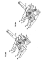
Figure 8A illustrates theswitch 10 having the transfer assembly arranged in a switch-deactuated position.Figure 8B illustrates the transfer assembly of theswitch 10 including theactuator 20,transfer carriage 40, a flip-flop mechanism, andcontacts actuator 20 via thetrigger 30, which causes thetransfer carriage 40 to move relative to theactuator 20. Theactuator 20 is moved to initiate delivery of thetransfer carriage 40 andfirst contact 12 toward thesecond contact 18. - When the
actuator 20 is moved toward thesecond contacts 18, a transfer barrier prevents movement of thecarriage 40 by providing an energy barrier. Preventing movement of thecarriage 40 while moving theactuator 20 causes transfer energy to build up in the flip-flop mechanism. Thetransfer carriage 40 is locked from movement until a sufficient amount of energy is input into the system. When a sufficient amount of energy is provided via thetrigger 30, thetransfer carriage 40 overcomes the transfer barrier. When the transfer barrier is overcome, the flip-flop mechanism changes states, thereby moving thecarriage 40 towards thesecond contacts 18. Theswitch 10 now is in the switch-actuated position and a transfer barrier prevents movement back to the switch-deactuated position. - Referring now to
Figures 8A-14B , various stages of select components within theswitch 10 are illustrated describing toggling of theswitch 10 between switch-actuated and switch-deactuated positions.Figures 8A and8B illustrate components of theswitch 10 arranged in astage 1 "release state."Figures 9A-9B illustrate the select components shown inFigure 8B arranged in astage 2 "first energy build up" state in which theactuator 20 is moved further towards thesecond contacts 18. Theactuator 20 presses against thetransfer carriage 40 to move thecam members 48 up to thecam balls 60 of the transfer barrier, such that thetransfer carriage 40 is at a transfer point. The first biasing member 44a is compressed, thereby creating and storing transfer energy in the first carriage biasing member 44a at the transfer point. -
Figures 10A-10B illustrate the select components ofFigure 8B arranged in a stage 3 "fly to on" state. If further pressure is applied to theactuator 20, thetransfer carriage 40 will overcome the transfer barrier and be free to move past the transfer point. In particular, the energy built up from the compression of the first biasing member 44a enables thecam members 48 of thetransfer carriage 40 to overcome the resistance of thecam balls 60. Thecam members 48 are allowed to move as a result of the space created by thesecond actuator cutouts 29. Thus, there is no force to resist movement of thetransfer carriage 40, towards thesecond contact 18. At this point, thecam members 48 quickly slide (i.e., or fly) over thecam balls 60. Thus, thecam balls 60 retract away from thetransfer carriage 40 by compression of theball biasing members 62 toward the ball stops 64. -
Figures 11A-11B illustrate the select components ofFigure 8B arranged in a stage 4 "switch on" state. Once thetransfer carriage 40 overcomes the transfer barrier and moves past thecam balls 60, thebridge plate 14 is delivered toward thesecond contacts 18. Thus, thefirst contacts 12 come into contact with thesecond contacts 18, thereby closing the circuit. This is analogous to the schematic wiring pattern illustrated inFigure 16 discussed above. Sufficient contact pressure is maintained between the first andsecond contacts second biasing member 44b. The energy built up from compression of the first biasing member 44a atstage 2 is released in pushing thebridge plate 14 towards thesecond contacts 18. -
Figures 12A-12B illustrate the select components ofFigure 8B arranged in a stage 5 "second energy pile up" state. At this point, even if theactuator 20 is released, the transfer barrier retains thetransfer carriage 40 in the "switch on" state such that contact between the first andsecond contacts actuator 20 must now be moved in a direction away from thesecond contacts 18 in order to toggle the switch to the switch-deactuated position. The first biasing member 44a is then compressed in a manner similar tostage 2, but from the opposite side.Second carriage plate 42b is slid throughfirst carriage cutout 49a, such that thesecond biasing surface 43b compresses the first biasing member 44a against thefirst biasing surface 43a of thefirst carriage plate 42a. A second transfer energy is stored at a second transfer point where thecam members 48 are pushed against thecam balls 60 from the opposite side. This energy storage configuration is analogous to the first energy storage configuration ofstage 2 illustrated inFigures 9A-9B . -
Figures 13A-13B illustrate the select components ofFigure 8B arranged in astage 6 "fly to off' state. After theactuator 20 is further released, thetransfer carriage 40 is pulled away from thesecond contacts 18 with sufficient force to overcome thecam balls 60. Thus, thecam members 48 slide quickly over thecam balls 60, thereby releasing the second transfer energy stored in stage 5. The release causes thebridge plate 14 to quickly separate from thesecond contacts 18. This configuration is analogous to the "fly to on" state of stage 3 illustrated inFigures 10A-10B , except that thetransfer carriage 40 andbridge plate 14 are moving in the opposite direction. After this stage, the select components of theswitch 10 return to thestage 1 "release" state. Thus, one switch-actuated/switch-deactuated position cycle is completed. - It is emphasized that this description represents one exemplary embodiment only and the invention is not limited to the specific arrangement as described herein. For instance, it will appreciated that the biasing
members - Referring now to
Figures 14A-14E , alocking device 50 maintains thetransfer carriage 40 in the closed circuit position (i.e., or "switch on" state) or maintains thetransfer carriage 40 in the "release" position.Figures 15A-15E illustrate partial perspective views of thelock device 50 of theswitch 10. Relevant components are shown for purposes of illustration. It is emphasized that thelock device 50 shown inFigures 14A-14E is exemplary only as other arrangements may be equally suitable. -
Figures 14A-14C illustrate thelock device 50 respectively in the "lock off, switch off" state, the "lock on, switch on" state, and the "lock off, switch on" state. According to one embodiment, thelock device 50 includes alock button 51. Thelock button 51 includes afastener 51a that connects to a reciprocatingmember 51b. The reciprocatingmember 51b is movable into and out of thehousing 70. According to another embodiment, alock biasing member 54 is disposed within thelock button 51. Preferably, thelock biasing member 54 is disposed annularly about thefastener member 51a and reciprocatingmember 51b. Thelock button 51 is connected to thehousing 70 through anannular collar 59. Thelock button 51 andcollar 59 provide a biasingspace 56 therebetween, such that thelock button 51 may move into and out of theannular collar 56. Areciprocating space 55 is provided within thehousing 70, such that the reciprocatingmember 51b may reciprocate into and out of thehousing 70. - The
lock button 51 connects with alock device lever 52 to engage acatch member 58. As shown inFigures 14A , thelever 52 is shown released from thecatch member 58 in a "lock off, switch off" position. InFigure 14B , thelever 52 is shown engaged with thecatch member 58 in a "lock on, switch on" position.Figure 14C illustrates thelever 52 released from thecatch member 58 in a "lock off, switch on" position. -
Figures 14D-14E illustrate an alternative embodiment for thelock device 50. As shown inFigures 14D-14E , alock device shoulder 38 may be employed such that theswitch 10 is locked in a switch-deactuated position and released in a switch-actuated position.Figure 14D shows thelock device 50 in a "lock on, switch-deactuated" stage.Figure 14E shows thelock device 50 in a "lock off, switch-actuated" stage. - It will be appreciated that while the
lock device 50 may be preferable for switch operation, it may not be necessary in all embodiments. -
Figures 16 (A-B) - 19(A-B) illustrate multiple schematic arrangements for using anon-teasable switch 100. In brief:Figure 16A illustrates one embodiment of aswitch 100 as a single-pole, single-throw, non-teasable switch. This configuration is analogous to the wiring pattern having a motor shown inFigure 15 .Figure 16B illustrates a schematic for multiple single-pole, single-throw,non-teasable switches 100 arranged in parallel. -
Figure 17A illustrates an embodiment of anon-teasable switch 101 arranged in a double-pole, single-throw,non-teasable switch 101 configuration.Figure 17B illustrates multiple double-pole, single-throw,non-teasable switches 101 arranged in parallel. -
Figure 18A illustrates a single-pole, single-throw,non-teasable switch 103 and further including a number ofbus bars 102 to drive a number of loads.Figure 18B illustrates multiple-pole, single-throw,non-teasable switches 103 including a number of bus bars to drive a number of loads. - The switch as herein described prevents teasing that may occur between contacts in a circuit, thereby preventing arcing and sparking. Welding of contacts may also be avoided when using this switch. Preferably, the switch is incorporated in a trigger for a hand operated power tool. It is emphasized that this application is exemplary only. The switch is not limited only to use with electrical circuits as described. It may also be adaptable for use with other known on/off circuits for preventing teasing. The non-teasable switch is also not limited only to the uses described herein. Other arrangements that produce similar functionality may be equally suitable.
- Furthermore, it is particularly noted that various embodiments of the switch may be adapted for use with various currents and voltages, and either AC or DC power. Moreover, as previously indicated, the present invention is not limited exclusively to electrical circuit interruption. Moreover, the switch is not limited only to the particular arrangement of electrical circuits shown and described herein. Embodiments of the present invention may be suitable for use with circuits operating at a variety of AC and DC voltages, and/or a variety of AC and DC currents.
- Although the switch is described herein in terms of a device that is integrated into an electrical circuit, this is exemplary only. Certain embodiments of the present invention may be suitable for partial or total integration into larger circuits, appliances, or other devices. However, other embodiments of the present invention may be suitable for use as modules used with other circuits or devices.
- The above specification, examples and data provide a complete description of the manufacture and use of the composition of the invention. Since many embodiments of the invention can be made without departing from the scope of the invention, the invention resides in the claims hereinafter appended.
Claims (9)
- A non-teasable switch (10), comprising:a first contact (12) movable toward a second contact (18) from a switch-deactuated position to a switch-actuated position and movable away from the said second contact (18) from said switch-actuated position back to said switch deactuated position, said first contact (12) releasably contacting said second contact (18) in said switch-actuated position and said first contact (12) being separated from said second contact (18) in said switch-deactuated position;a transfer carriage (40) operatively engaged with said first contact (12) and being movable toward and away from said second contact (18) between said switch-deactuated and switch-actuated positions, said transfer carriage (40) being arranged and configured to accommodate a flip-flop mechanism for bringing said first contact (12) into contact with said second contact (18) and for releasing said first contact (12) from said second contact (18); said flip-flop mechanism overcoming a transfer barrier between said switch-actuated and switch-deactuated positions; andan actuator (20) operative engaged with said transfer carriage (40) and being movable toward and away from said second contact (18), said actuator (20) being movable so as to impart movement on said transfer carriage (40) and said first contact (12) between said switch-deactuated and switch-actuated positions, and said actuator (20) being movable so as to impart movement on said transfer carriage (40) to overcome said transfer barrier from both said switch-deactuated and switch actuated positions;wherein, through said actuator (20) and transfer carriage (40), said first contact (12) is transferred into and out of contact with said second contact (18), wherein said flip-flop mechanism includes a bridge plate (14) cooperating with second carriage cutouts (49b) and a second biasing member (44b) to bias said bridge plate (14) toward said second contact (18), said bridge plate (14) including said first contact (12) connected thereto, whereby said bridge plate (14) is biased so as to provide contact between said first and second contact (12, 18),characterized in that the non-teasable switch comprises a lock device (50), said lock device (50) being configured and arranged such that when said lock device (50) is operated it maintains the said actuator (20) and said transfer carriage (40) either in said switch-actuated position or in said switch-deactuated position,and in that the flip-flop mechanism further includes first and second carriage plates (42a,42b) cooperating with first carriage cutouts (49a) and a first biasing member (44a), said flip-flop mechanism cooperating with said actuator (20) to move said transfer carriage (40) within said actuator (20) relative to the movement of said actuator (20).
- The non-teasable switch according to claim 1, further comprising a housing (70) and cover (90) for containing and protecting said switch (10).
- The non-teasable switch according to claim 1, further comprising at least one terminal connector and at least one line input (L1,L2), wherein said terminal connector is connectable to at least one of an electric load and a passive component (non-power consuming component), said line input being receivable of connectors to connect said switch with a power source (P).
- The non-teasable switch according to claim 1, further comprising a trigger (30), said trigger (30) being constructed and arranged to respectively activate and retease said actuator (20) and transfer carriage (40) in said switch-actuated position, and said switch-deactuated position.
- The non-teasable switch according to claim 1, wherein said actuator (20) and said transfer carriage (40) move relative to one another.
- The non-teasable switch according to claim 1, wherein said actuator (20) includes a shaft (22) and a carriage container (24) disposed at one end of said shaft (22), said carriage container (24) contains said transfer carriage (40), said carriage container (24) including cutouts (28,29) so as to allow said transfer carriage (40) to move within said carriage container (24).
- The non-teasable switch according to claim 1, wherein said first contact (12) includes two contact points.
- The non-teasable switch according to claim 1, wherein said transfer carriage (40) includes at least one cam member (48) to cooperate with said transfer barrier, said cam member (40) being movable toward one side of said transfer barrier in a first transfer energy storage stage when said transfer carriage (40) and actuator (20) are moved to a switch-actuated position, said cam member (40) being movable toward another side of said transfer barrier in a second transfer energy storage stage when said transfer carriage (40) and said actuator (20) are moved to a switch-deactuated position.
- The non-teasable switch according to claim 8, wherein said transfer barrier includes at least one cam ball (60), at least one ball biasing member (62), and at least one ball stop (64), wherein one end of the ball biasing member (62) couples to the ball stop (64) and the other end of the ball biasing member (62) couples to the cam ball (60), wherein said ball biasing member (62) biases said cam ball (60) toward said transfer carriage (40) and resists movement of said transfer carriage (40) by means of said cam member (48).
Priority Applications (1)
| Application Number | Priority Date | Filing Date | Title |
|---|---|---|---|
| EP06256509.8A EP1936645B1 (en) | 2006-12-21 | 2006-12-21 | Circuit interrupter that produces snap-action connection and disconnection between electrical contacts |
Applications Claiming Priority (1)
| Application Number | Priority Date | Filing Date | Title |
|---|---|---|---|
| EP06256509.8A EP1936645B1 (en) | 2006-12-21 | 2006-12-21 | Circuit interrupter that produces snap-action connection and disconnection between electrical contacts |
Publications (2)
| Publication Number | Publication Date |
|---|---|
| EP1936645A1 EP1936645A1 (en) | 2008-06-25 |
| EP1936645B1 true EP1936645B1 (en) | 2013-07-03 |
Family
ID=38045585
Family Applications (1)
| Application Number | Title | Priority Date | Filing Date |
|---|---|---|---|
| EP06256509.8A Active EP1936645B1 (en) | 2006-12-21 | 2006-12-21 | Circuit interrupter that produces snap-action connection and disconnection between electrical contacts |
Country Status (1)
| Country | Link |
|---|---|
| EP (1) | EP1936645B1 (en) |
Families Citing this family (3)
| Publication number | Priority date | Publication date | Assignee | Title |
|---|---|---|---|---|
| EP3101671B1 (en) | 2015-06-04 | 2019-02-20 | Satori Electric Co., Ltd. | Switch |
| JP6720901B2 (en) | 2017-03-14 | 2020-07-08 | オムロン株式会社 | Trigger switch |
| EP3926653A1 (en) | 2020-06-15 | 2021-12-22 | ABB Power Grids Switzerland AG | Contact bounce reduction system |
Citations (1)
| Publication number | Priority date | Publication date | Assignee | Title |
|---|---|---|---|---|
| EP0702381A1 (en) * | 1994-09-16 | 1996-03-20 | Heinrich Kopp Ag | Device for securing the switching position of an electric push-button switch |
Family Cites Families (5)
| Publication number | Priority date | Publication date | Assignee | Title |
|---|---|---|---|---|
| US2347874A (en) | 1942-09-07 | 1944-05-02 | Gen Motors Corp | Electric switch |
| US4154996A (en) | 1977-05-12 | 1979-05-15 | Mcgraw-Edison Company | Positive break snap action switch |
| DE19930558A1 (en) | 1998-07-24 | 2000-01-27 | Marquardt Gmbh | Electrical switch has an actuating mechanism, a fixed contact and switch contact for operating an elastic mechanism to influence the movement of a slide. |
| DE10034670A1 (en) | 2000-07-17 | 2002-01-31 | Kopp Heinrich Ag | Device for mechanically securing the ON and OFF switch position of an electrical pressure switch |
| DE10217406B4 (en) | 2001-04-19 | 2014-05-15 | Marquardt Gmbh | Electric switch |
-
2006
- 2006-12-21 EP EP06256509.8A patent/EP1936645B1/en active Active
Patent Citations (1)
| Publication number | Priority date | Publication date | Assignee | Title |
|---|---|---|---|---|
| EP0702381A1 (en) * | 1994-09-16 | 1996-03-20 | Heinrich Kopp Ag | Device for securing the switching position of an electric push-button switch |
Also Published As
| Publication number | Publication date |
|---|---|
| EP1936645A1 (en) | 2008-06-25 |
Similar Documents
| Publication | Publication Date | Title |
|---|---|---|
| US7211758B2 (en) | Circuit interrupter that produces snap-action connection and disconnection between electrical contacts | |
| CN1092392C (en) | Electromagnetic switching device | |
| US6864769B2 (en) | Lockout mechanism for residual current devices | |
| EP1936645B1 (en) | Circuit interrupter that produces snap-action connection and disconnection between electrical contacts | |
| CN108364835B (en) | High-voltage direct-current relay | |
| DE19930558A1 (en) | Electrical switch has an actuating mechanism, a fixed contact and switch contact for operating an elastic mechanism to influence the movement of a slide. | |
| CN102870185B (en) | Electrical switchgear and state indication component thereof | |
| KR102374581B1 (en) | High voltage latching relay with manual actuator | |
| CN109509653B (en) | Switching device and associated switch | |
| EP0720771B1 (en) | Switch device | |
| CN101840807B (en) | Switch module of electrical installation device | |
| US3143606A (en) | Depressible trigger switch with manual adjustable contact means | |
| CN107958806A (en) | Device and method for latching and system comprising the latching device | |
| US3908473A (en) | Linear motion snap-action mechanism | |
| CN108878185B (en) | Two-stage automatic change-over switch electric appliance | |
| CN212848145U (en) | Handle push switch with self-locking function | |
| CN212365849U (en) | Manual switching-on and switching-off device of electric spring operating mechanism | |
| CN217934478U (en) | Connector assembly | |
| KR100584826B1 (en) | Trigger Mechanism Device of Medium-voltage Switches and Breakers | |
| CN112185722A (en) | Action mechanism and switching device | |
| JPS645791Y2 (en) | ||
| CN117542708A (en) | Ground fault circuit breaker | |
| JP2023004202A (en) | switch device | |
| KR100486749B1 (en) | Hand operated trip device in three phase switch | |
| CN105027251A (en) | Contact device and circuit breaker |
Legal Events
| Date | Code | Title | Description |
|---|---|---|---|
| PUAI | Public reference made under article 153(3) epc to a published international application that has entered the european phase |
Free format text: ORIGINAL CODE: 0009012 |
|
| AK | Designated contracting states |
Kind code of ref document: A1 Designated state(s): AT BE BG CH CY CZ DE DK EE ES FI FR GB GR HU IE IS IT LI LT LU LV MC NL PL PT RO SE SI SK TR |
|
| AX | Request for extension of the european patent |
Extension state: AL BA HR MK RS |
|
| 17P | Request for examination filed |
Effective date: 20081112 |
|
| 17Q | First examination report despatched |
Effective date: 20081219 |
|
| AKX | Designation fees paid |
Designated state(s): AT BE BG CH CY CZ DE DK EE ES FI FR GB GR HU IE IS IT LI LT LU LV MC NL PL PT RO SE SI SK TR |
|
| GRAP | Despatch of communication of intention to grant a patent |
Free format text: ORIGINAL CODE: EPIDOSNIGR1 |
|
| RIN1 | Information on inventor provided before grant (corrected) |
Inventor name: LUI, NELSON MAN HOI |
|
| GRAS | Grant fee paid |
Free format text: ORIGINAL CODE: EPIDOSNIGR3 |
|
| GRAA | (expected) grant |
Free format text: ORIGINAL CODE: 0009210 |
|
| AK | Designated contracting states |
Kind code of ref document: B1 Designated state(s): AT BE BG CH CY CZ DE DK EE ES FI FR GB GR HU IE IS IT LI LT LU LV MC NL PL PT RO SE SI SK TR |
|
| REG | Reference to a national code |
Ref country code: GB Ref legal event code: FG4D |
|
| REG | Reference to a national code |
Ref country code: CH Ref legal event code: EP Ref country code: AT Ref legal event code: REF Ref document number: 620179 Country of ref document: AT Kind code of ref document: T Effective date: 20130715 |
|
| REG | Reference to a national code |
Ref country code: IE Ref legal event code: FG4D |
|
| REG | Reference to a national code |
Ref country code: CH Ref legal event code: NV Representative=s name: MARKS AND CLERK (LUXEMBOURG) LLP, CH |
|
| REG | Reference to a national code |
Ref country code: DE Ref legal event code: R096 Ref document number: 602006037081 Country of ref document: DE Effective date: 20130829 |
|
| PG25 | Lapsed in a contracting state [announced via postgrant information from national office to epo] |
Ref country code: SI Free format text: LAPSE BECAUSE OF FAILURE TO SUBMIT A TRANSLATION OF THE DESCRIPTION OR TO PAY THE FEE WITHIN THE PRESCRIBED TIME-LIMIT Effective date: 20130703 |
|
| REG | Reference to a national code |
Ref country code: AT Ref legal event code: MK05 Ref document number: 620179 Country of ref document: AT Kind code of ref document: T Effective date: 20130703 |
|
| REG | Reference to a national code |
Ref country code: NL Ref legal event code: VDEP Effective date: 20130703 |
|
| REG | Reference to a national code |
Ref country code: LT Ref legal event code: MG4D |
|
| PG25 | Lapsed in a contracting state [announced via postgrant information from national office to epo] |
Ref country code: SE Free format text: LAPSE BECAUSE OF FAILURE TO SUBMIT A TRANSLATION OF THE DESCRIPTION OR TO PAY THE FEE WITHIN THE PRESCRIBED TIME-LIMIT Effective date: 20130703 Ref country code: PT Free format text: LAPSE BECAUSE OF FAILURE TO SUBMIT A TRANSLATION OF THE DESCRIPTION OR TO PAY THE FEE WITHIN THE PRESCRIBED TIME-LIMIT Effective date: 20131104 Ref country code: IS Free format text: LAPSE BECAUSE OF FAILURE TO SUBMIT A TRANSLATION OF THE DESCRIPTION OR TO PAY THE FEE WITHIN THE PRESCRIBED TIME-LIMIT Effective date: 20131103 Ref country code: CY Free format text: LAPSE BECAUSE OF FAILURE TO SUBMIT A TRANSLATION OF THE DESCRIPTION OR TO PAY THE FEE WITHIN THE PRESCRIBED TIME-LIMIT Effective date: 20130724 Ref country code: LT Free format text: LAPSE BECAUSE OF FAILURE TO SUBMIT A TRANSLATION OF THE DESCRIPTION OR TO PAY THE FEE WITHIN THE PRESCRIBED TIME-LIMIT Effective date: 20130703 Ref country code: AT Free format text: LAPSE BECAUSE OF FAILURE TO SUBMIT A TRANSLATION OF THE DESCRIPTION OR TO PAY THE FEE WITHIN THE PRESCRIBED TIME-LIMIT Effective date: 20130703 Ref country code: BE Free format text: LAPSE BECAUSE OF FAILURE TO SUBMIT A TRANSLATION OF THE DESCRIPTION OR TO PAY THE FEE WITHIN THE PRESCRIBED TIME-LIMIT Effective date: 20130703 |
|
| PG25 | Lapsed in a contracting state [announced via postgrant information from national office to epo] |
Ref country code: LV Free format text: LAPSE BECAUSE OF FAILURE TO SUBMIT A TRANSLATION OF THE DESCRIPTION OR TO PAY THE FEE WITHIN THE PRESCRIBED TIME-LIMIT Effective date: 20130703 Ref country code: GR Free format text: LAPSE BECAUSE OF FAILURE TO SUBMIT A TRANSLATION OF THE DESCRIPTION OR TO PAY THE FEE WITHIN THE PRESCRIBED TIME-LIMIT Effective date: 20131004 Ref country code: NL Free format text: LAPSE BECAUSE OF FAILURE TO SUBMIT A TRANSLATION OF THE DESCRIPTION OR TO PAY THE FEE WITHIN THE PRESCRIBED TIME-LIMIT Effective date: 20130703 Ref country code: PL Free format text: LAPSE BECAUSE OF FAILURE TO SUBMIT A TRANSLATION OF THE DESCRIPTION OR TO PAY THE FEE WITHIN THE PRESCRIBED TIME-LIMIT Effective date: 20130703 Ref country code: FI Free format text: LAPSE BECAUSE OF FAILURE TO SUBMIT A TRANSLATION OF THE DESCRIPTION OR TO PAY THE FEE WITHIN THE PRESCRIBED TIME-LIMIT Effective date: 20130703 Ref country code: ES Free format text: LAPSE BECAUSE OF FAILURE TO SUBMIT A TRANSLATION OF THE DESCRIPTION OR TO PAY THE FEE WITHIN THE PRESCRIBED TIME-LIMIT Effective date: 20131014 |
|
| PG25 | Lapsed in a contracting state [announced via postgrant information from national office to epo] |
Ref country code: CY Free format text: LAPSE BECAUSE OF FAILURE TO SUBMIT A TRANSLATION OF THE DESCRIPTION OR TO PAY THE FEE WITHIN THE PRESCRIBED TIME-LIMIT Effective date: 20130703 |
|
| PG25 | Lapsed in a contracting state [announced via postgrant information from national office to epo] |
Ref country code: SK Free format text: LAPSE BECAUSE OF FAILURE TO SUBMIT A TRANSLATION OF THE DESCRIPTION OR TO PAY THE FEE WITHIN THE PRESCRIBED TIME-LIMIT Effective date: 20130703 Ref country code: EE Free format text: LAPSE BECAUSE OF FAILURE TO SUBMIT A TRANSLATION OF THE DESCRIPTION OR TO PAY THE FEE WITHIN THE PRESCRIBED TIME-LIMIT Effective date: 20130703 Ref country code: CZ Free format text: LAPSE BECAUSE OF FAILURE TO SUBMIT A TRANSLATION OF THE DESCRIPTION OR TO PAY THE FEE WITHIN THE PRESCRIBED TIME-LIMIT Effective date: 20130703 Ref country code: DK Free format text: LAPSE BECAUSE OF FAILURE TO SUBMIT A TRANSLATION OF THE DESCRIPTION OR TO PAY THE FEE WITHIN THE PRESCRIBED TIME-LIMIT Effective date: 20130703 Ref country code: RO Free format text: LAPSE BECAUSE OF FAILURE TO SUBMIT A TRANSLATION OF THE DESCRIPTION OR TO PAY THE FEE WITHIN THE PRESCRIBED TIME-LIMIT Effective date: 20130703 |
|
| PLBE | No opposition filed within time limit |
Free format text: ORIGINAL CODE: 0009261 |
|
| STAA | Information on the status of an ep patent application or granted ep patent |
Free format text: STATUS: NO OPPOSITION FILED WITHIN TIME LIMIT |
|
| 26N | No opposition filed |
Effective date: 20140404 |
|
| REG | Reference to a national code |
Ref country code: DE Ref legal event code: R097 Ref document number: 602006037081 Country of ref document: DE Effective date: 20140404 |
|
| PG25 | Lapsed in a contracting state [announced via postgrant information from national office to epo] |
Ref country code: TR Free format text: LAPSE BECAUSE OF FAILURE TO SUBMIT A TRANSLATION OF THE DESCRIPTION OR TO PAY THE FEE WITHIN THE PRESCRIBED TIME-LIMIT Effective date: 20130703 |
|
| PG25 | Lapsed in a contracting state [announced via postgrant information from national office to epo] |
Ref country code: HU Free format text: LAPSE BECAUSE OF FAILURE TO SUBMIT A TRANSLATION OF THE DESCRIPTION OR TO PAY THE FEE WITHIN THE PRESCRIBED TIME-LIMIT; INVALID AB INITIO Effective date: 20061221 Ref country code: BG Free format text: LAPSE BECAUSE OF FAILURE TO SUBMIT A TRANSLATION OF THE DESCRIPTION OR TO PAY THE FEE WITHIN THE PRESCRIBED TIME-LIMIT Effective date: 20130703 |
|
| REG | Reference to a national code |
Ref country code: FR Ref legal event code: PLFP Year of fee payment: 10 |
|
| PGFP | Annual fee paid to national office [announced via postgrant information from national office to epo] |
Ref country code: IE Payment date: 20151209 Year of fee payment: 10 |
|
| PGFP | Annual fee paid to national office [announced via postgrant information from national office to epo] |
Ref country code: MC Payment date: 20151028 Year of fee payment: 10 |
|
| REG | Reference to a national code |
Ref country code: FR Ref legal event code: PLFP Year of fee payment: 11 |
|
| PG25 | Lapsed in a contracting state [announced via postgrant information from national office to epo] |
Ref country code: MC Free format text: LAPSE BECAUSE OF NON-PAYMENT OF DUE FEES Effective date: 20170102 |
|
| REG | Reference to a national code |
Ref country code: IE Ref legal event code: MM4A |
|
| PG25 | Lapsed in a contracting state [announced via postgrant information from national office to epo] |
Ref country code: IE Free format text: LAPSE BECAUSE OF NON-PAYMENT OF DUE FEES Effective date: 20161221 |
|
| REG | Reference to a national code |
Ref country code: FR Ref legal event code: PLFP Year of fee payment: 12 |
|
| PGFP | Annual fee paid to national office [announced via postgrant information from national office to epo] |
Ref country code: LU Payment date: 20191219 Year of fee payment: 14 |
|
| PG25 | Lapsed in a contracting state [announced via postgrant information from national office to epo] |
Ref country code: LU Free format text: LAPSE BECAUSE OF NON-PAYMENT OF DUE FEES Effective date: 20201221 |
|
| PGFP | Annual fee paid to national office [announced via postgrant information from national office to epo] |
Ref country code: CH Payment date: 20230103 Year of fee payment: 17 |
|
| PGFP | Annual fee paid to national office [announced via postgrant information from national office to epo] |
Ref country code: GB Payment date: 20231220 Year of fee payment: 18 |
|
| PGFP | Annual fee paid to national office [announced via postgrant information from national office to epo] |
Ref country code: IT Payment date: 20231228 Year of fee payment: 18 Ref country code: FR Payment date: 20231221 Year of fee payment: 18 Ref country code: DE Payment date: 20231214 Year of fee payment: 18 |