EP1936543A1 - Hochfrequenzidentifikation - Google Patents
Hochfrequenzidentifikation Download PDFInfo
- Publication number
- EP1936543A1 EP1936543A1 EP07255011A EP07255011A EP1936543A1 EP 1936543 A1 EP1936543 A1 EP 1936543A1 EP 07255011 A EP07255011 A EP 07255011A EP 07255011 A EP07255011 A EP 07255011A EP 1936543 A1 EP1936543 A1 EP 1936543A1
- Authority
- EP
- European Patent Office
- Prior art keywords
- resonant
- array
- rfid tag
- frequencies
- transmitter
- Prior art date
- Legal status (The legal status is an assumption and is not a legal conclusion. Google has not performed a legal analysis and makes no representation as to the accuracy of the status listed.)
- Withdrawn
Links
Images

Classifications
-
- G—PHYSICS
- G06—COMPUTING; CALCULATING OR COUNTING
- G06K—GRAPHICAL DATA READING; PRESENTATION OF DATA; RECORD CARRIERS; HANDLING RECORD CARRIERS
- G06K19/00—Record carriers for use with machines and with at least a part designed to carry digital markings
- G06K19/06—Record carriers for use with machines and with at least a part designed to carry digital markings characterised by the kind of the digital marking, e.g. shape, nature, code
- G06K19/067—Record carriers with conductive marks, printed circuits or semiconductor circuit elements, e.g. credit or identity cards also with resonating or responding marks without active components
-
- G—PHYSICS
- G06—COMPUTING; CALCULATING OR COUNTING
- G06K—GRAPHICAL DATA READING; PRESENTATION OF DATA; RECORD CARRIERS; HANDLING RECORD CARRIERS
- G06K19/00—Record carriers for use with machines and with at least a part designed to carry digital markings
- G06K19/06—Record carriers for use with machines and with at least a part designed to carry digital markings characterised by the kind of the digital marking, e.g. shape, nature, code
- G06K19/08—Record carriers for use with machines and with at least a part designed to carry digital markings characterised by the kind of the digital marking, e.g. shape, nature, code using markings of different kinds or more than one marking of the same kind in the same record carrier, e.g. one marking being sensed by optical and the other by magnetic means
- G06K19/10—Record carriers for use with machines and with at least a part designed to carry digital markings characterised by the kind of the digital marking, e.g. shape, nature, code using markings of different kinds or more than one marking of the same kind in the same record carrier, e.g. one marking being sensed by optical and the other by magnetic means at least one kind of marking being used for authentication, e.g. of credit or identity cards
Definitions
- the present invention relates to radio frequency identification, and particularly but not exclusively to a passive writable radio-frequency identification tag.
- Radio frequency identification generally involves generating a radio-frequency electromagnetic signal that interacts with a tag or similar device. The interaction of the signal with the tag is detected and used to decode information recorded in the tag. RFID has been proposed for a variety of applications, such as inventory control.
- RFID has been proposed as a replacement to optical identification systems, such as barcode readers, but has not been widely adopted because of the higher cost, size and/or weight of RFID tags compared to barcodes.
- Another problem is the difficulty in encoding information in an RFID tag.
- the information may be encoded within the chip.
- the chip adds to the cost of the RFID tag.
- EP-A-0 845 754 discloses an RFID system in which the tag comprises a plurality of resonators, such as thin dipoles.
- the resonators may be coupled to resonance modifying means, such that application of a sufficiently high RF power level changes the resonant frequency of the resonators.
- AU-A-50630/93 discloses an RFID system with resonators having different detection and bum-out frequencies; foil forming the bum-out resonator has a narrow part that bums out due to high current density.
- an RFID tag comprising a plurality of resonators having corresponding discrete resonant frequencies, each resonator including a weak point arranged to create an electrical discontinuity when the resonator is subjected to a high power RF signal at the corresponding resonant frequency.
- the resonators may comprise printed or embedded conductive tracks or shapes, each having a thinner section forming the weak point.
- an RF transmitter for reading information from and writing information to a resonant RFID tag, the transmitter being operable to transmit a signal at a selectable one of a plurality of frequencies corresponding to resonant frequencies of the RFID tag, the transmitter having a low power setting for reading information from the resonant array RFID tag and a high power setting for writing information to the resonant array RFID tag.
- an RF transmitter for reading a resonant RFID tag, the transmitter being operable to transmit a signal at a selectable one of a plurality of frequencies corresponding to resonant frequencies of the RFID tag, and further including a power detector for detecting a reduction in the output power of the RF transmitter so as to determine the presence of a resonant component of the resonant array at the selected frequency.
- an RF transmitter 1 generates an RF signal that of variable frequency over the frequencies F1 to F8.
- a resonator array 2 comprises one or more resonators A1 to A8 that resonate at the corresponding frequencies F1 to F8.
- a detector 3 detects when the RF signal is at a resonant frequency F1-F8 of one of the resonators A1-A8 and generates an output that indicates that the presence of the corresponding resonator A1-A8 has been detected.
- This output indicates information encoded within the resonator array; in other words, the information is represented by the presence or absence of each of the resonators A1-A8.
- the resonator array 2 is suitable for use as an RFID tag.
- the detector 3 may comprise a power detector 3 coupled to the RF transmitter 1.
- the detector 3 may detect attenuation of the RF signal after it has passed the resonator array 2: when the RF signal is at one of the resonant frequencies F1-F8, the RF signal is attenuated and the attenuation is detected by the detector 3.
- the resonators A1-A8 may consist of a plurality of dipole antennas of different lengths.
- the resonant frequency F1-F8 of each antenna is determined by its length, with shorter lengths giving higher frequencies, and the length being a fraction of the wavelength of the resonant frequency.
- the lengths of the antennas are predetermined so that the antennas have corresponding ones of the resonant frequencies F1-F8.
- the information present in an RFID tag may be encoded in the number and lengths of the resonators in the resonator array 2.
- Each resonator A1-A8 may consist of a length of conductive material, with a common ground plane.
- the conductive material may printed or otherwise applied onto an insulating substrate, thus providing a printable RFID tag that can be manufactured without the disadvantages of size, cost and/or weight of RFID tags in the prior art.
- the conductive material may be embedded within a substrate and/or the object to be tagged.
- the resonators A1-A8 need not be linear, but may have any shape or form so long as they resonate at the desired frequencies F1-F8.
- each of the resonators A1-A8 has an electrically weak point P1-P8 along its length, arranged to undergo a change when the corresponding resonator A1-A8 is subjected to a high power RF signal at the corresponding resonant frequency.
- the electrically weak point P1-P8 may 'blow' (e.g. change to an open circuit condition) when it is no longer able to withstand the electric field or absorbed energy from the high power RF signal, thereby separating the resonator A1-A8 into electrically disconnected parts, neither of which are resonant at any of the frequencies F1-F8.
- the RF transmitter 1 is operated at a higher power level than is used for reading; either the power level of the RF transmitter 1 is selectable between a low power 'read' level and a high power 'write' level, or separate RF transmitters are used for reading and writing.
- the RF transmitter is set to transmit at the resonant frequency F1-F8 of the resonator A1-A8 to be 'blown', and the high power RF signal is transmitted under conditions sufficient to 'blow' that resonator.
- the writing process may be repeated for other ones of the resonators A1-A8 until the desired information is recorded.
- the writing process is essentially irreversible, but this is not a disadvantage as the RFID tag is not intended to be re-usable. Of course, it would be possible to blow further resonators at a subsequent stage, thereby changing further '0' bits to '1'.
- the resonant array 2 consists of the resonators A1-A8, each corresponding to a 'bit' of information to be recorded, giving one 8-bit byte of information.
- all of the resonators A1-A8 are functional, corresponding to a bit value of'00000000'.
- the RF transmitter 1 is set to the high power level, and the RF signal frequency is set to F2, F4, F6 and F8 in turn, essentially discontinuously and remaining at each frequency for a period sufficient to blow the corresponding resonators.
- the RF transmitter 1 is set to the low power level, and the RF signal frequency is set to each of F1 to F8 in turn.
- the detector 3 detects absorption of the signal by the resonant array 2; if the signal is attenuated, a bit value '1' is recorded, otherwise a bit value of '0' is recorded.
- the recorded bit values indicate the byte recorded in the resonant array 2.
- Embodiments of the invention provide a light, low-cost RFID tag that enables applications that have hitherto not been possible.
- the tag could be applied to disc media such as a CD, DVD or Blu-ray disc, without substantially affecting the balance of the disc media.
- the resonant array 2 may be embedded within the disc at the time of manufacture, with data being written to the resonant array 2 subsequently. Alternatively, the resonant array 2 may be printed on the surface of the disc.
- the tag may be embedded in other products at the time of manufacture, and subsequently written to create an identity code for the product.
- the identity code may be written by the purchaser or end user by means of a dedicated RF transmitter 1, allowing products to be tagged so as to deter theft.
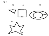
- FIG. 3 shows further embodiments of resonators A1 - A4 according to embodiments of the invention.
- the thick lines represent conductive tracks and the thin lines are the weak points P1-P4 that may be blown to alter the resonant characteristics of the artefact.
- the resonators may be of any shape that provides an electromagnetic path that includes a thin conductor that will be blown upon the application of a high burst of RF energy at the corresponding resonant frequency.
- the resonators may be formed as logos, pictograms, letters or symbols of any shape and may even form a printed description of the product.
- the resonators may be part of the structure of the product, or may be embedded within the product.
Applications Claiming Priority (1)
| Application Number | Priority Date | Filing Date | Title |
|---|---|---|---|
| GB0625812A GB2445171A (en) | 2006-12-22 | 2006-12-22 | An rfid tag comprising an array of resonators each comprising a conductive part including a weak section. |
Publications (1)
| Publication Number | Publication Date |
|---|---|
| EP1936543A1 true EP1936543A1 (de) | 2008-06-25 |
Family
ID=37758975
Family Applications (1)
| Application Number | Title | Priority Date | Filing Date |
|---|---|---|---|
| EP07255011A Withdrawn EP1936543A1 (de) | 2006-12-22 | 2007-12-21 | Hochfrequenzidentifikation |
Country Status (3)
| Country | Link |
|---|---|
| US (1) | US20080218352A1 (de) |
| EP (1) | EP1936543A1 (de) |
| GB (1) | GB2445171A (de) |
Families Citing this family (5)
| Publication number | Priority date | Publication date | Assignee | Title |
|---|---|---|---|---|
| US20110140842A1 (en) * | 2009-12-15 | 2011-06-16 | Morton Greene | System and method for identifying a genuine printed document |
| US9740975B2 (en) | 2015-06-08 | 2017-08-22 | Xerox Corporation | Printing system architecture for encoding chip-less RFID tags in real time |
| US9734446B2 (en) | 2015-11-17 | 2017-08-15 | Xerox Corporation | Post application editing of multiresonator chipless radio frequency identification (RFID) |
| US9691048B1 (en) | 2015-12-22 | 2017-06-27 | Xerox Corporation | Photoconductive multi-resonator chipless RFID |
| US9640855B1 (en) | 2015-12-22 | 2017-05-02 | Xerox Corporation | Photosensitive multi-resonator chipless RFID |
Citations (3)
| Publication number | Priority date | Publication date | Assignee | Title |
|---|---|---|---|---|
| DE2235309A1 (de) * | 1971-08-02 | 1973-02-15 | Ncr Co | Datenabtastvorrichtung |
| DE4338554A1 (de) * | 1992-11-14 | 1994-05-19 | Krone Ag | Verfahren und Schaltungsanordnung zur elektronischen Kennzeichnung von Gegenständen |
| EP0845754A1 (de) | 1992-10-29 | 1998-06-03 | Gordian Holding Corporation | Automatisches Radiofrequenz-Identifizierungssystem |
Family Cites Families (11)
| Publication number | Priority date | Publication date | Assignee | Title |
|---|---|---|---|---|
| JPS4877695A (de) * | 1971-12-30 | 1973-10-18 | ||
| US4423423A (en) * | 1980-09-09 | 1983-12-27 | L. Barker & Williamson, Inc. | Broad bandwidth folded dipole antenna |
| DE10148919A1 (de) * | 2001-10-04 | 2003-04-10 | Philips Corp Intellectual Pty | Verfahren und Vorrichtung zur Ortung bewegter Gegenstände |
| US7102522B2 (en) * | 2002-12-24 | 2006-09-05 | 3M Innovative Properties Company | Tamper-indicating radio frequency identification antenna and sticker, a radio frequency identification antenna, and methods of using the same |
| JP4383959B2 (ja) * | 2003-05-28 | 2009-12-16 | キヤノン株式会社 | 光電変換装置およびその製造方法 |
| US7040139B2 (en) * | 2003-06-10 | 2006-05-09 | Smiths Detection Inc. | Sensor arrangement |
| US7026936B2 (en) * | 2003-09-30 | 2006-04-11 | Id Solutions, Inc. | Distributed RF coupled system |
| US7132946B2 (en) * | 2004-04-08 | 2006-11-07 | 3M Innovative Properties Company | Variable frequency radio frequency identification (RFID) tags |
| JP4578139B2 (ja) * | 2004-04-13 | 2010-11-10 | 富士通株式会社 | 所定の情報を受信する情報処理装置、プログラム、記憶媒体および方法 |
| US7463155B2 (en) * | 2005-06-03 | 2008-12-09 | Sensormatic Electronics Corporation | Techniques for radio frequency identification and electronic article surveillance receivers |
| US20070063818A1 (en) * | 2005-09-22 | 2007-03-22 | Intermec Ip Corp. | Automatic data collection device, method and article for avoiding interference |
-
2006
- 2006-12-22 GB GB0625812A patent/GB2445171A/en not_active Withdrawn
-
2007
- 2007-12-21 US US11/962,664 patent/US20080218352A1/en not_active Abandoned
- 2007-12-21 EP EP07255011A patent/EP1936543A1/de not_active Withdrawn
Patent Citations (4)
| Publication number | Priority date | Publication date | Assignee | Title |
|---|---|---|---|---|
| DE2235309A1 (de) * | 1971-08-02 | 1973-02-15 | Ncr Co | Datenabtastvorrichtung |
| EP0845754A1 (de) | 1992-10-29 | 1998-06-03 | Gordian Holding Corporation | Automatisches Radiofrequenz-Identifizierungssystem |
| DE4338554A1 (de) * | 1992-11-14 | 1994-05-19 | Krone Ag | Verfahren und Schaltungsanordnung zur elektronischen Kennzeichnung von Gegenständen |
| AU5063093A (en) | 1992-11-14 | 1994-06-02 | Krone Aktiengesellschaft | Method and circuit configuration for electronically labelling articles |
Also Published As
| Publication number | Publication date |
|---|---|
| GB2445171A (en) | 2008-07-02 |
| US20080218352A1 (en) | 2008-09-11 |
| GB0625812D0 (en) | 2007-02-07 |
| GB2445171A8 (en) | 2008-07-10 |
Similar Documents
| Publication | Publication Date | Title |
|---|---|---|
| EP2286485B1 (de) | Hochfrequenztransponder | |
| US5204681A (en) | Radio frequency automatic identification system | |
| US7804407B2 (en) | Combination EAS and RFID label or tag with controllable read range | |
| EP2250631B1 (de) | Verfahren und vorrichtungen zum bewahren der privatsphäre in einem rfid-system | |
| Bhattacharyya et al. | RFID tag antenna based temperature sensing in the frequency domain | |
| US7245219B2 (en) | RFID tag for an object having metallic portions, tag coupler and method thereof | |
| US7663491B2 (en) | Substrate damage detection mechanism using RFID tag | |
| US20080088460A1 (en) | Combination eas and rfid label or tag using a hybrid rfid antenna | |
| US20080030324A1 (en) | Data communication with sensors using a radio frequency identification (RFID) protocol | |
| EP1936543A1 (de) | Hochfrequenzidentifikation | |
| US20090189768A1 (en) | Combination security tag using a perimeter rfid antenna surrounding an eas element and method thereof | |
| KR101270543B1 (ko) | 메타물질을 이용한 칩리스 알에프 아이디 시스템 및 그 인식 방법 | |
| EP3217327A1 (de) | Rfid-etikett mit manipulationssicherer anordnung | |
| US20040217171A1 (en) | Electronic identification label and interrogator for use therewith | |
| JP2922474B2 (ja) | 物の真正を証明するターゲットおよびそのシステム | |
| NL1017068C2 (nl) | Signaaltransponder voor CD- en DVD-dozen. | |
| JP4115478B2 (ja) | Rfタグの情報読み出し方法および情報書き込み方法 | |
| US7317398B2 (en) | Security and identification label and the production and use thereof | |
| US20070205900A1 (en) | Rfid tag with antenna and sense conductor | |
| US20060132288A1 (en) | Method of reading information from RF tag and method of writing information therein | |
| AU2003100727A4 (en) | Reduction in the Dynamic Range of an Electronic Label's Received Signal | |
| KR200443445Y1 (ko) | 복수의 전자태그에 의해 상태감시가 가능한 안테나 | |
| KR20110075209A (ko) | 공진 태그와 태그 정보 인식 장치 및 그 방법 | |
| KR20090113947A (ko) | Rfid 태그 코일안테나 | |
| JP2006140607A (ja) | 通信装置 |
Legal Events
| Date | Code | Title | Description |
|---|---|---|---|
| PUAI | Public reference made under article 153(3) epc to a published international application that has entered the european phase |
Free format text: ORIGINAL CODE: 0009012 |
|
| AK | Designated contracting states |
Kind code of ref document: A1 Designated state(s): AT BE BG CH CY CZ DE DK EE ES FI FR GB GR HU IE IS IT LI LT LU LV MC MT NL PL PT RO SE SI SK TR |
|
| AX | Request for extension of the european patent |
Extension state: AL BA HR MK RS |
|
| AKX | Designation fees paid | ||
| REG | Reference to a national code |
Ref country code: DE Ref legal event code: 8566 |
|
| STAA | Information on the status of an ep patent application or granted ep patent |
Free format text: STATUS: THE APPLICATION IS DEEMED TO BE WITHDRAWN |
|
| 18D | Application deemed to be withdrawn |
Effective date: 20081230 |