EP1936331A1 - Encoder and light receiving device for encoder - Google Patents
Encoder and light receiving device for encoder Download PDFInfo
- Publication number
- EP1936331A1 EP1936331A1 EP06811517A EP06811517A EP1936331A1 EP 1936331 A1 EP1936331 A1 EP 1936331A1 EP 06811517 A EP06811517 A EP 06811517A EP 06811517 A EP06811517 A EP 06811517A EP 1936331 A1 EP1936331 A1 EP 1936331A1
- Authority
- EP
- European Patent Office
- Prior art keywords
- light
- detected
- encoder
- scale
- photodetecting
- Prior art date
- Legal status (The legal status is an assumption and is not a legal conclusion. Google has not performed a legal analysis and makes no representation as to the accuracy of the status listed.)
- Withdrawn
Links
- 238000006073 displacement reaction Methods 0.000 description 19
- 230000003287 optical effect Effects 0.000 description 19
- 238000005259 measurement Methods 0.000 description 18
- 239000010408 film Substances 0.000 description 17
- 238000001514 detection method Methods 0.000 description 15
- 238000010276 construction Methods 0.000 description 4
- 238000010586 diagram Methods 0.000 description 4
- 230000015572 biosynthetic process Effects 0.000 description 3
- 230000000694 effects Effects 0.000 description 3
- OKTJSMMVPCPJKN-UHFFFAOYSA-N Carbon Chemical compound [C] OKTJSMMVPCPJKN-UHFFFAOYSA-N 0.000 description 2
- 229910052799 carbon Inorganic materials 0.000 description 2
- 230000000052 comparative effect Effects 0.000 description 2
- 239000000428 dust Substances 0.000 description 2
- 239000011521 glass Substances 0.000 description 2
- 239000011347 resin Substances 0.000 description 2
- 229920005989 resin Polymers 0.000 description 2
- XAGFODPZIPBFFR-UHFFFAOYSA-N aluminium Chemical compound [Al] XAGFODPZIPBFFR-UHFFFAOYSA-N 0.000 description 1
- 229910052782 aluminium Inorganic materials 0.000 description 1
- 230000006866 deterioration Effects 0.000 description 1
- 239000000463 material Substances 0.000 description 1
- 238000000034 method Methods 0.000 description 1
- 238000012986 modification Methods 0.000 description 1
- 230000004048 modification Effects 0.000 description 1
- 239000010409 thin film Substances 0.000 description 1
Images








Classifications
-
- G—PHYSICS
- G01—MEASURING; TESTING
- G01D—MEASURING NOT SPECIALLY ADAPTED FOR A SPECIFIC VARIABLE; ARRANGEMENTS FOR MEASURING TWO OR MORE VARIABLES NOT COVERED IN A SINGLE OTHER SUBCLASS; TARIFF METERING APPARATUS; MEASURING OR TESTING NOT OTHERWISE PROVIDED FOR
- G01D5/00—Mechanical means for transferring the output of a sensing member; Means for converting the output of a sensing member to another variable where the form or nature of the sensing member does not constrain the means for converting; Transducers not specially adapted for a specific variable
- G01D5/26—Mechanical means for transferring the output of a sensing member; Means for converting the output of a sensing member to another variable where the form or nature of the sensing member does not constrain the means for converting; Transducers not specially adapted for a specific variable characterised by optical transfer means, i.e. using infrared, visible, or ultraviolet light
- G01D5/32—Mechanical means for transferring the output of a sensing member; Means for converting the output of a sensing member to another variable where the form or nature of the sensing member does not constrain the means for converting; Transducers not specially adapted for a specific variable characterised by optical transfer means, i.e. using infrared, visible, or ultraviolet light with attenuation or whole or partial obturation of beams of light
- G01D5/34—Mechanical means for transferring the output of a sensing member; Means for converting the output of a sensing member to another variable where the form or nature of the sensing member does not constrain the means for converting; Transducers not specially adapted for a specific variable characterised by optical transfer means, i.e. using infrared, visible, or ultraviolet light with attenuation or whole or partial obturation of beams of light the beams of light being detected by photocells
- G01D5/347—Mechanical means for transferring the output of a sensing member; Means for converting the output of a sensing member to another variable where the form or nature of the sensing member does not constrain the means for converting; Transducers not specially adapted for a specific variable characterised by optical transfer means, i.e. using infrared, visible, or ultraviolet light with attenuation or whole or partial obturation of beams of light the beams of light being detected by photocells using displacement encoding scales
-
- G—PHYSICS
- G01—MEASURING; TESTING
- G01D—MEASURING NOT SPECIALLY ADAPTED FOR A SPECIFIC VARIABLE; ARRANGEMENTS FOR MEASURING TWO OR MORE VARIABLES NOT COVERED IN A SINGLE OTHER SUBCLASS; TARIFF METERING APPARATUS; MEASURING OR TESTING NOT OTHERWISE PROVIDED FOR
- G01D5/00—Mechanical means for transferring the output of a sensing member; Means for converting the output of a sensing member to another variable where the form or nature of the sensing member does not constrain the means for converting; Transducers not specially adapted for a specific variable
- G01D5/26—Mechanical means for transferring the output of a sensing member; Means for converting the output of a sensing member to another variable where the form or nature of the sensing member does not constrain the means for converting; Transducers not specially adapted for a specific variable characterised by optical transfer means, i.e. using infrared, visible, or ultraviolet light
- G01D5/32—Mechanical means for transferring the output of a sensing member; Means for converting the output of a sensing member to another variable where the form or nature of the sensing member does not constrain the means for converting; Transducers not specially adapted for a specific variable characterised by optical transfer means, i.e. using infrared, visible, or ultraviolet light with attenuation or whole or partial obturation of beams of light
- G01D5/34—Mechanical means for transferring the output of a sensing member; Means for converting the output of a sensing member to another variable where the form or nature of the sensing member does not constrain the means for converting; Transducers not specially adapted for a specific variable characterised by optical transfer means, i.e. using infrared, visible, or ultraviolet light with attenuation or whole or partial obturation of beams of light the beams of light being detected by photocells
- G01D5/347—Mechanical means for transferring the output of a sensing member; Means for converting the output of a sensing member to another variable where the form or nature of the sensing member does not constrain the means for converting; Transducers not specially adapted for a specific variable characterised by optical transfer means, i.e. using infrared, visible, or ultraviolet light with attenuation or whole or partial obturation of beams of light the beams of light being detected by photocells using displacement encoding scales
- G01D5/3473—Circular or rotary encoders
-
- G—PHYSICS
- G01—MEASURING; TESTING
- G01D—MEASURING NOT SPECIALLY ADAPTED FOR A SPECIFIC VARIABLE; ARRANGEMENTS FOR MEASURING TWO OR MORE VARIABLES NOT COVERED IN A SINGLE OTHER SUBCLASS; TARIFF METERING APPARATUS; MEASURING OR TESTING NOT OTHERWISE PROVIDED FOR
- G01D5/00—Mechanical means for transferring the output of a sensing member; Means for converting the output of a sensing member to another variable where the form or nature of the sensing member does not constrain the means for converting; Transducers not specially adapted for a specific variable
Definitions
- the present invention relates to an optical encoder and a photodetecting device for an encoder.
- an optical encoder described in Patent Document 1 is known as a conventional optical encoder.
- the conventional encoder has an optical scale in which lattice windows having different diffracting patterns are annularly arranged, and diffracted patterns of light to be detected to the lattice windows through a slit are picked up by an image sensor. Then, the lattice windows are specified from the picked-up diffracted patterns, and also the positions of the lattice windows are specified on the basis of the positions of the diffracted patterns in the image, whereby the absolute angle of a measurement target is detected.
- Patent Document 1 Japanese Published Examined Patent Application No. H08-10145
- the absolute angle is directly detected from the position of each specified lattice window. Therefore, when the arrangement relationship of the respective members constituting an optical system is displaced due to difficulties of disk processing of the scale, subsequent age-based deterioration or the like, and thus the irradiated position of the light to be detected with respect to the scale is displaced from a reference, the detection accuracy of the absolute angle is lowered.
- the present invention has been implemented to solve the above problem, and has an object to provide an encoder that can detect an absolute angle with high accuracy even when the irradiated position of light to be detected with respect to a scale is displaced from a reference and a photodetecting device for an encoder used for such an encoder.
- an encoder includes: a rotating member; a light source device for emitting light to be detected to the rotating member; and a photodetecting device including a scale having a plurality of photodetecting elements arranged thereon, and an output portion for outputting an output signal based on the light intensity of the light to be detected made incident to the photodetecting elements through the rotating member, wherein the photodetecting elements are arranged along an annularly arranged line on the scale, and the rotating member is designed so that, in the scale, an area containing mutually separate parts of the arranged line is set as a bright portion to which the light to be detected is irradiated, and an area containing the other portion excluding the parts of the arranged line concerned is set as a dark portion to which no light to be detected is irradiated.
- the encoder has the rotating member that sets, in the scale having the plurality of photodetecting elements arranged annularly thereon, the area containing mutually separate parts of the arranged line as the bright portion to which the light to be detected is irradiated, and the area containing the other portion excluding the mutually separate parts of the arranged line, as the dark portion to which no light to be detected is irradiated. Accordingly, at least two light intensity peaks are obtained from a one-dimensional profile of the output signal from the photodetecting elements, and the absolute angle can be calculated by specifying the photodetecting element corresponding to one light intensity peak.
- a relative angle between one light intensity peak and the other light intensity peak can be grasped from the shape of the bright portion formed on the scale in advance.
- the deviation amount of the relative angle is calculated as a corrected amount, and the corrected amount is added to or subtracted from the absolute angle determined from one light intensity peak, whereby the absolute angle can be detected with high accuracy even when the irradiated position of the light to be detected with respect to the scale is displaced from the reference.
- a straight-line light transmitting portion is formed in the rotating member, and the bright portion is formed of the light to be detected that has passed through the light transmitting portion.
- two light intensity peaks are obtained from a one-dimensional profile of the output signal, and a reference relative angle therebetween is uniquely provided as 180°. Accordingly, a corrected amount can be easily calculated.
- the width of one end side is different from the width of the other end side. Since this causes a difference in the width (full width at half maximum) between the two light intensity peaks, these light intensity peaks can be discriminated. Accordingly, it becomes possible to extend the angle detection range of the encoder.
- a straight-line light reflecting portion is formed in the rotating member, and the bright portion is formed of the light to be detected reflected from the light reflecting portion.
- the light transmitting portion is preferably a slit.
- the construction of the light transmitting portion is simplified, whereby a reduction in the cost of the encoder can be realized.
- the width of one end side is different from the width of the other end side. Since this causes a difference in the width (full width at half maximum) between the two light intensity peaks, these light intensity peaks can be discriminated. Accordingly, it becomes possible to extend the angle detection range of the encoder.
- the photodetecting elements are arranged in a zigzag form along the arranged line. In this case, the resolution of the angle detection can be enhanced while keeping the scale compact.
- a light absorbing film is formed in the area excluding the area where the photodetecting elements are arranged. According to such a construction, the effect of multiple reflections of the light to be detected, etc., can be moderated, and the S/N ratio of the one-dimensional profile of the output signal obtained from the photodetecting elements can be enhanced.
- a photodetecting device for an encoder includes: a scale having a plurality of photodetecting elements arranged thereon; and an output portion for outputting an output signal based on light intensity of light to be detected made incident to the photodetecting elements, wherein the photodetecting elements are arranged along an annularly arranged line on the scale, and in the scale, a light absorbing film is formed in an area excluding the area where the photodetecting elements are arranged.
- an area containing mutually separate parts of the arranged line, in the scale having the plurality of photodetecting elements arranged annularly thereon, can be set as a bright portion to which light to be detected is irradiated, and an area containing the other portion excluding the parts of the arranged line can be set as a dark portion to which no light to be detected is irradiated. Accordingly, at least two light intensity peaks are obtained from a one-dimensional profile of the output signal from the photodetecting elements, and the absolute angle can be calculated by specifying the photodetecting element corresponding to one light intensity peak.
- a relative angle between one light intensity peak and the other light intensity peak can be grasped from the shape of the bright portion formed on the scale in advance.
- the relative angle between the light intensity peaks on detecting the angle is displaced from the reference relative angle by a fixed amount. Therefore, in this encoder, the deviation amount of the relative angle is calculated as a corrected amount, and the corrected amount is added to or subtracted from the absolute angle determined from one light intensity peak, whereby the absolute angle can be detected with high accuracy even when the irradiated position of the light to be detected with respect to the scale is displaced from the reference.
- the output portion has a shift register that makes the output signal based on light intensity output in sequence from the photodetecting elements, and the shift register is arranged inside the arranged line. It becomes possible to miniaturize the scale by arranging the shift register in an extra space inside the arranged line.
- the photodetecting elements are arranged in a zigzag form along the arranged line. In this case, the resolution of the angle detection can be enhanced while keeping the scale compact.
- the absolute angle can be detected with high accuracy.
- photodetecting device 108...slit plate (rotating member) having a toothed gear, 110... PD (photodetecting element), 111... scale plate, 112... output portion, 113... shift register, 117, 120... slit (light transmitting portion), L101... first arranged line, L102... second arranged line, W101... slit width of one end side, W102... slit width of the other end side, X... optical axis
- Fig. 1 is a perspective view showing an encoder according to a first embodiment of the present invention.
- the encoder 1 shown in Fig. 1 is a so-called absolute type rotary encoder, and it is a device for detecting the absolute angle of a measurement target (not shown) such as the handle of a vehicle or the like.
- This encoder 1 is equipped with a rotational shaft 2 linked to the measurement target, and a disk 3 having a toothed gear fixed to the rotational shaft 2.
- the disk 3 having the toothed gear is rotated in the direction of an arrow A in connection with the rotation of the rotational shaft 2 interlocked with the measurement target.
- Fig. 2 is a perspective view showing an optical system S of the encoder 1.
- the optical system S of the encoder 1 is composed of an LED (light source device) 6 being a spot light source for emitting light to be detected, a photodetecting device (photodetecting device for an encoder) 7 that is disposed so as to face LED 6 and photodetects the light to be detected, a rotating plate (rotating member) 8 having a toothed gear which is engaged with the disk 3 having the toothed gear, and a pair of collimating lens 9A and 9B disposed so as to sandwich the rotating plate 8 having the toothed gear therebetween.
- the photodetecting device 7 has a scale plate 11 having a plurality of PDs (photodetecting elements) 10 arranged thereon, and an output portion 12 for outputting an output signal from each PD 10.
- a first arranged line L1 and a second arranged line L2 are concentrically set on the scale plate 11, and the respective PDs 10 are annularly arranged in a zigzag form on the arranged lines L1 and L2.
- Angle information is allocated to the respective PDs 10 from the first PD 10 1 (0°) to the last PD 10 n (359.5°), for example, at an angular interval of 0.5° in the clockwise direction.
- a light absorbing film 18 of black resin which contains carbon, for example is formed in the area on the surface of the scale plate 11 excluding the area where PDs 10 are arranged.
- the output portion 12 has a plurality of (four in this embodiment) shift registers 13, a video line 14 and a signal processor 16.
- the respective shift registers 13 are arranged in a substantially rectangular form concentrically with the scale plate 11 at the inside of the respective arranged lines L1 and L2, and supply scan signals to the respective PDs 10 for outputting the output signal based on the light intensity of the photodetected light to be detected.
- the video line 14 is concentrically arranged at the outside of the arranged lines L1 and L2, and outputs an output signal from each PD 10 to the signal processor 16.
- the signal processor 16 outputs the output signal received from each PD 10 via the video line 14 to the outside.
- a supply line (not shown) for a driving signal to each shift register 13 is connected between PD 10 1 and PD 10 n , for example.
- the rotating plate 8 having the toothed gear has a light transmitting portion 17 through which a part of the light to be detected emitted from LED 6 is passed.
- the light transmitting portion 17 is formed of, for example, glass in a straight-line shape so as to pass through the center of the rotating plate 8 having the toothed gear.
- the light transmitting portion 17 is formed so that the width is gradually reduced from one end side to the other end side, and the width W1 of one end side is about twice the width W2 of the other end side.
- a light absorbing film 21 is formed of the same material as the light absorbing film 18 on the surface of the rotating plate 8 having the toothed gear in the area excluding the light transmitting portion 17.
- the light transmitting portion 17 When the measurement target rotates, the light transmitting portion 17 is rotated in the direction of an arrow B around the optical axis X of the light to be detected in cooperation between the disk 3 having the toothed gear and the rotating plate 8 having the toothed gear as shown in Fig. 1 .
- the light to be detected that has passed through the light transmitting portion 17 is designed to have the same straight-line shape as that of the light transmitting portion 17. Accordingly, as shown in Fig.
- a bright portion 19 to which the light to be detected is irradiated is formed in an area containing mutually separate parts of the arranged lines L1 and L2 of the scale plate 11, that is, a straight-line area containing parts of intersections between the arranged lines L1 and L2 and one end side and the other end side of the light transmitting portion 17. Furthermore, a part of the light to be detected that has not passed through the light transmitting portion 17 is absorbed by the light absorbing film 21. Accordingly, a dark portion 20 to which no light to be detected is irradiated is formed in the area of the scale plate 11 excluding the bright portion 19.
- the light to be detected when the light to be detected is emitted from LED 6 being a spot light source, the light to be detected is collimated and bundled by the collimating lens 9A, and then made incident to the light transmitting portion 17 as shown in Fig. 2 .
- the light to be detected which has passed through the light transmitting portion 17 and formed into the straight-line shape is converged by the collimating lens 9B, and one end side and the other end side of the light to be detected are made incident, at two spots, to the respective PDs 10 arranged annularly.
- the output signal based on the light intensity of the photodetected light to be detected is output from each PD 10, and output from the signal processor 16 to the outside.
- the output signals obtained from the respective PDs 10 are collected, and a one-dimensional profile of the light intensity of the light to be detected with respect to the respective PDs 10 is acquired (step S01).
- the light to be detected that has passed through the light transmitting portion 17 is made incident, at two spots, to the respective PDs 10 arranged annularly, and thus when the one-dimensional profile is analyzed, two light intensity peaks P1 and P2 that are mutually separated are obtained as shown in Fig. 7(a) .
- the width W1 of one end side of the light transmitting portion 17 is about twice the width W2 of the other end side in the encoder 1
- the light intensity peak P1 has a full width at half maximum about twice that of the light intensity peak P2.
- the obtained light intensity peaks P1 and P2 are binarized on the basis of a predetermined comparative level (step S02).
- the PD 10 corresponding to the center at half maximum of the binarized light intensity peak P1 is set as a reference point to determine the absolute angle
- the PD 10 corresponding to the center at half maximum of the light intensity peak P2 is set as a relative point to determine a relative angle between the light intensity peaks P1 and P2.
- the angles of the reference point and the relative point are detected on the basis of the angle information allocated to the respective PDs 10 (step S03).
- the light transmitting portion 17 is formed in a straight-line shape. Therefore, when the light transmitting portion 17 does not have a positional displacement with respect to the scale plate 11, the relative angle (hereinafter, referred to as "reference relative angle") between the reference point and the relative point is uniquely calculated as 180°.
- the relative angle between the reference point and the relative point on detecting the angle is calculated as 180°+ ⁇ °.
- the ⁇ ° is calculated as a corrected amount for the angular displacement (step S04). Then, the corrected amount ⁇ ° is added to (or subtracted from) the angle of the reference point detected in step S03, thereby calculating the absolute angle at the reference point (step S05).
- the light to be detected is passed through the straight-line light transmitting portion 17 formed in the rotating plate 8 having the toothed gear, whereby the bright portion 19 to which the light to be detected is irradiated is formed in the area containing the mutually separate parts of the arranged lines L1 and L2 on the scale plate 11, and the dark portion 20 to which no light to be detected is irradiated is formed in the area excluding the bright portion 19.
- the two light intensity peaks P1 and P2 are obtained from the one-dimensional profile of the output signal from the PDs 10, and the absolute angle can be calculated by specifying the PD 10 corresponding to one light intensity peak P1.
- the relative angle between the light intensity peaks P1 and P2 can be uniquely calculated as 180° based on the shape of the light transmitting portion 17.
- the relative angle between the light intensity peaks P1 and P2 on detecting the angle is displaced from the reference relative angle by a fixed amount.
- the absolute angle of the measurement target can be detected with high accuracy by calculating the deviation amount of the relative angle as a corrected amount ⁇ °, and adding/subtracting the corrected amount ⁇ ° to/from the absolute angle determined by the light intensity peak P1.
- the light transmitting portion 17 has a straight-line shape, and thus a formation thereof is easy and a reduction in the cost of the encoder 1 can be realized.
- the light transmitting portion 17 is formed of glass, and thus it is less likely to be clogged with dust as compared with a case where a slit is used, so that it is possible to suppress a reduction in the detection accuracy of the absolute angle due to level reduction in the output signal, etc., even when the encoder 1 is used for a long time.
- the width W1 of one end side thereof is different from the width W2 of the other end side.
- the reference point and the relative point can be discriminated from each other, and extensive angle detection across the entire circumference of the scale becomes possible.
- the respective shift registers 13 are arranged in the substantially rectangular form so as to be concentric with the scale plate 11 inside the arranged lines L1 and L2.
- the photodetecting device 7 can be further miniaturized by arranging the respective shift registers 13 in an extra space inside the arranged lines L1 and L2.
- the respective PDs 10 are arranged in the zigzag form over the annularly arranged lines L1 and L2.
- the above arrangement of PDs 10 can keep the scale plate 11 compact and enhance the resolution of the angle detection.
- the light absorbing film 18 is formed in the area on the surface of the scale plate 11 in the area excluding the area where the PDs 10 are arranged. Accordingly, the effect of multiple reflection of the light to be detected, etc., can be moderated, and the S/N ratio of the one-dimensional profile of the output signal obtained from the respective PDs 10 can be enhanced.
- an encoder according to a second embodiment of the present invention will be described.
- the difference of an encoder 30 according to the second embodiment from the first embodiment in which the light to be detected is passed through the light transmitting portion 17 of the rotation plate 8 having the toothed gear resides in that light to be detected emitted from LED 6 is reflected from a light reflecting portion 32 of the rotating plate 31 having the toothed gear when the bright portion 19 and the dark portion 20 are formed on the scale plate 11.
- the rotating plate 31 having the toothed gear has a light reflecting portion 32 for reflecting a part of the light to be detected emitted from LED 6.
- the light reflecting portion 32 is formed of, for example, aluminum thin film in a straight-line shape so as to pass through the center of the rotating plate 31 having the toothed gear.
- the light reflecting portion 32 is formed, similar to the light transmitting portion 17 in the first embodiment, so that the width is gradually reduced from one end side to the other end side, and the width W3 of one end side of the light reflecting portion 32 is about twice the width W4 of the other end side.
- a light absorbing film 33 which is formed of black resin containing carbon, for example, is formed at the portion excluding the light reflecting portion 32 by print or the like.
- LED 6 is disposed at the center portion of the scale plate 11 in the photodetecting device 7.
- the bright portion 19 to which the light to be detected is irradiated is formed in the area containing the mutually separate parts of the arranged lines L1 and L2 in the scale plate 11, that is, the straight-line area containing the parts of intersections between the arranged lines L1 and L2 and one end side and the other end side of the light reflecting portion 32 (see Fig. 5 ).
- the absolute angle of the measurement target can be detected with high accuracy even when the irradiated position of the light to be detected with respect to the scale plate 11 is displaced from the reference.
- the straight-line light reflecting portion 32 is used to form the bright portion 19 and the dark portion 20, and thus it is unlikely to be clogged with dust as in the case of the first embodiment. Accordingly, even when the encoder 30 is used for a long time, the detection accuracy of the absolute angle can be suppressed from being reduced due to level reduction in the output signal, etc. Furthermore, LED 6 is disposed at the scale plate 11 side, and thus the optical system Sa can be miniaturized. In addition, for the light reflecting portion 32, the width W3 of one end side is different from the width W4 of the other end side. Therefore, by analyzing the one-dimensional profile of the output signal obtained from the respective PDs 10, the light intensity peaks P1 and P2 having different full widths at half maximum are obtained. Accordingly, the reference point and the relative point can be discriminated from each other, and extensive angle detection across the entire circumference of the scale becomes possible.
- the present invention is not limited to the above embodiments.
- the light absorbing film 21 is formed in the area excluding the light transmitting portion 17 in the rotating plate 8 having the toothed gear.
- a light reflecting film (not shown) may be formed.
- the light to be detected which does not pass through the light transmitting portion 17 is reflected from the light reflecting film to the opposite side of the photodetecting device 7, so that the S/N ratio of the one-dimensional profile of the output signal obtained from the respective PDs 10 can be enhanced.
- the formation pattern of the bright portion 19 and the dark portion 20 to be formed on the scale plate 11 may be inverted. That is, in the encoder 1, a light absorbing film (or light reflecting film) may be formed at the forming position of the light transmitting portion 17 in the rotating plate 8 having the toothed gear, and a light transmitting portion may be formed in the other area. Likewise, in the encoder 30, a light transmitting portion (or light absorbing film) may be formed at the forming position of the light reflecting portion 32 in the rotating plate 31 having the toothed gear, and a light transmitting portion may be formed in the other area.
- a one-dimensional profile of an output signal obtained from the respective PDs 10 is inverted from that in the case of the above embodiment, however, by carrying out the same processing as the aforementioned step S01 to step S05 based on two bottoms obtained in place of the light intensity peaks P1 and P2, the absolute angle of a measurement target can be detected with high accuracy even when the irradiated position of light to be detected with respect to the scale plate 11 is displaced from a reference.
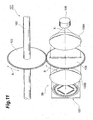
- Fig. 11 is a perspective view showing an embodiment of an encoder according to the present invention.
- the encoder 101 shown in Fig. 11 is a so-called absolute type rotary encoder, and it is a device for detecting the absolute angle of a measurement target (not shown) such as the handle of a vehicle or the like.
- This encoder 101 is equipped with a rotational shaft 102 linked to the measurement target, and a disk 103 having a toothed gear fixed to the rotational shaft 102.
- the disk 103 having the toothed gear is rotated in the direction of an arrow A in connection with the rotation of the rotational shaft 102 interlocked with the measurement target.
- Fig. 12 is a perspective view showing an optical system Sb of the encoder 101.
- the optical system Sb of the encoder 101 is composed of an LED (light source device) 106 being a spot light source for emitting light to be detected, a photodetecting device (photodetecting device for an encoder) 107 that is disposed so as to face LED 6 and photodetects the light to be detected, a slit plate (rotating member) 108 having a toothed gear which is engaged with the disk 103 having the toothed gear, and a pair of collimating lens 109A and 109B disposed so as to sandwich the slit plate 108 having the toothed gear therebetween.
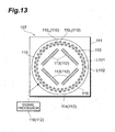
- the photodetecting device 107 has a scale plate 111 having a plurality of PDs (photodetecting elements) 110 arranged thereon, and an output portion 112 for outputting an output signal from each PD 110.
- a first arranged line L101 and a second arranged line L102 are concentrically set on a rim portion of the scale plate 111, and the respective PDs 110 are annularly arranged in a zigzag form on the arranged lines L101 and L102.
- Angle information is allocated to the respective PDs 110 from the first PD 110 1 (0°) to the last PD 110 n (359.5°), for example, at an angular interval of 0.5° in the clockwise direction.
- the output portion 112 has a plurality of (four in this embodiment) shift registers 113, a video line 114 and a signal processor 116.
- the respective shift registers 113 are arranged in a substantially rectangular form concentrically with the scale plate 111 at the inside of the respective arranged lines L101 and L102, and supply scan signals to the respective PDs 110 for outputting the output signal based on the light intensity of the photodetected light to be detected.
- the video line 114 is concentrically arranged at the outside of the arranged lines L101 and L102, and outputs an output signal from each PD 110 to the signal processor 116.
- the signal processor 116 outputs the output signal received from each PD 110 via the video line 114 to the outside.
- a supply line (not shown) for a driving signal to each shift register 113 is connected between PD 110 1 and PD 110 n , for example.
- the slit plate 108 having the toothed gear has a slit 117 through which a part of the light to be detected emitted from LED 106 is passed.
- the slit 117 is formed in a straight-line shape so as to pass through the center of the slit plate 108 having the toothed gear.
- the slit 117 is formed so that the slit width is gradually reduced from one end side to the other end side, and the slit width W101 of one end side is about twice the slit width W102 of the other end side.
- the slit 117 When the measurement target rotates, the slit 117 is rotated in the direction of an arrow B around the optical axis X of the light to be detected in cooperation between the disk 103 having the toothed gear and the slit plate 108 having the toothed gear as shown in Fig. 11 .
- the light to be detected that has passed through the slit 117 has the same straight-line shape as the shape of the slit 117, and intersects, as shown in Fig. 15 , at two spots of one end side and the other end side different in the slit width from each other, with the respective arranged lines L101 and L102.
- the light to be detected when the light to be detected is emitted from LED 106 being a spot light source, the light to be detected is collimated and bundled by the collimating lens 109A, and then made incident to the slit 117 as shown in Fig. 12 .
- the light to be detected which has passed through the slit 117 and formed into the straight-line shape is converged by the collimating lens 109B, and one end side and the other end side of the light to be detected are made incident, at two spots, to the respective PDs 110 arranged annularly.
- the output signal based on the light intensity of the photodetected light to be detected is output from each PD 110, and output from the signal processor 116 to the outside.
- the output signals obtained from the respective PDs 110 are collected, and a one-dimensional profile of the light intensity of the light to be detected with respect to the respective PDs 110 is acquired (step S101).
- the light to be detected that has passed through the slit 117 is made incident, at two spots, to the respective PDs 110 arranged annularly, and thus when the one-dimensional profile is analyzed, two light intensity peaks P101 and P102 mutually separated are obtained as shown in Fig. 17(a) .
- the light intensity peak P101 has a full width at half maximum about twice that of the light intensity peak P102.
- the obtained light intensity peaks P101 and P102 are binarized on the basis of a predetermined comparative level (step S102).
- the PD 110 corresponding to the center at half maximum of the binarized light intensity peak P101 is set as a reference point to determine the absolute angle
- the PD 110 corresponding to the center at half maximum of the light intensity peak P102 is set as a relative point to determine a relative angle between the light intensity peaks P101 and P102.
- the angles of the reference point and the relative point are detected on the basis of the angle information allocated to the respective PDs 110 (step S103).
- the slit 117 is formed in a straight-line shape. Therefore, when the light transmitting portion 117 does not have a positional displacement with respect to the scale plate 111, the relative angle (hereinafter, referred to as "reference relative angle") between the reference point and the relative point is uniquely calculated, as 180°.
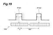
- the relative angle between the reference point and the relative point on detecting the angle is calculated as 180°+ ⁇ °.
- the ⁇ ° is calculated as a corrected amount for the angular displacement (step S104). Then, the corrected amount ⁇ ° is added to (or subtracted from) the angle of the reference point detected in step S103, thereby calculating the absolute angle at the reference point (step S 105).
- the light to be detected that has passed through the straight-line slit 117 is detected at two spots of the plurality of PDs 110 arranged annularly as a scale.
- the reference relative angle between the reference point corresponding to the light intensity peak P101 of the light to be detected and the relative point corresponding to the light intensity peak P102 can be uniquely calculated as 180° based on the shape of the straight-line slit 117.
- the absolute angle of the measurement target can be detected with high accuracy by calculating a corrected amount ⁇ ° based on the deviation amount of the relative angle between the reference point and relative point on detecting the angle from the reference relative angle.
- the light transmitting portion 117 has a straight-line shape, and thus a formation thereof is easy and a reduction in the cost of the encoder 101 can be realized. Furthermore, for the slit 117, the slit width W101 of one end side is different from the slit width W 102 of the other end side, and thus the light intensity peaks P101 and P102 having different full widths at half maximum are obtained. Accordingly, the reference point and the relative point can be discriminated from each other, and extensive angle detection across the entire circumference of the scale becomes possible.
- the respective PDs 110 are arranged in the zigzag form over the annularly arranged lines L101 and L102.
- the above arrangement of PDs 110 can keep the scale plate 111 compact and enhance the resolution of the angle detection.
- the photodetecting device 107 only the simple processing of outputting the output signal based on the light intensity of light to be detected made incident to each PD 110 to the outside is carried out at the photodetecting device 107 side, and thus the signal processing is rapidly carried out. Furthermore, a frame memory, etc., are not required, and miniaturization of the photodetecting device 107 and a reduction in the cost can be performed. Still furthermore, in the photodetecting device 107, the respective shift registers 113 are arranged in the substantially rectangular form so as to be concentric with the scale plate 111 inside the arranged lines L101 and L102. The photodetecting device 107 can be further miniaturized by arranging the respective shift registers 13 in an extra space inside the arranged lines L101 and L102.
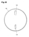
- a slit formed in the slit plate 108 having the toothed gear may have a shape, as in a slit 120 shown in Fig. 20 , where one end side and the other end side are separated.
- no light to be detected is transmitted from a center part of the slit plate 108 having the toothed gear, and thus the S/N ratio of the light intensity peaks P101 and P102 are enhanced, so that the absolute angle of the measurement target can be detected with a higher accuracy.
- photodetecting device 107 may be loaded with an A/D converter so as to make the output signal from each PD 110 as a digital output.
- the slit width W101 of one end side of the slit 117 and the slit width W102 of the other end side may be equal to each other.
- the reference point cannot be discriminated from the reference point, so that the angle detection range of the encoder 101 is substantially limited to a range of 180°. Therefore, a gear or the like (not shown) that rotates the slit plate 108 having the toothed gear half round with respect to one round of the disk 103 having the toothed gear may be interposed.
- an encoder includes: a rotating member having a slit formed thereon; a light source device for emitting light to be detected to the slit; and a photodetecting device including a scale having a plurality of photodetecting elements arranged thereon, and an output portion for outputting an output signal based on the light intensity of the light to be detected made incident to the photodetecting elements after passing through the slit, wherein the photodetecting elements are arranged along an annularly arranged line on the scale, and the light to be detected that has passed through the slit intersects with the arranged line at, at least, two spots mutually separated.
- the light to be detected that has passed through the slit is detected at, at least, two mutually separate spots of the plurality of photodetecting elements arranged annularly as a scale.
- a relative angle of the reference point from the other point can be grasped from the shape of the slit in advance.
- the slit has a positional displacement with respect to the scale, a relative angle between the reference point and the other point on detecting the angle is displaced from the reference relative angle by a fixed amount.
- the deviation amount of the relative angle is calculated as a corrected amount, and the corrected amount is added to or subtracted from an absolute angle indicated by the reference point, whereby the absolute angle can be detected with high accuracy even when the slit has a positional displacement with respect to the scale.
- the slit has a straight-line shape, and an end side and the other end side of the light to be detected that has passed through the slit respectively intersect with the arranged line. It is easy to form the straight line slit, whereby a reduction in the cost of the encoder can be realized
- the width of one end side is different from the width of the other end side. In this case, since an output signal having different peaks at the reference point and the other point is obtained, the reference point can be discriminated from the other point.
- the photodetecting elements are arranged in a zigzag form along the arranged line. In this case, the resolution of the angle detection can be enhanced while keeping the scale compact.
- a photodetecting device for an encoder includes: a scale having a plurality of photodetecting elements arranged thereon; and an output portion for outputting an output signal based on light intensity of light to be detected made incident to the photodetecting elements, wherein the photodetecting elements are arranged along an annularly arranged line on the scale.
- the photodetecting device for an encoder includes the plurality of photodetecting elements arranged annularly as a scale. Therefore, by interposing a rotating member having a slit formed thereon between the same and a light source device, it becomes possible to detect the light to be detected that has passed through the slit at, at least, two spots mutually separated. At this time, by providing either one of the points where the output signal peaks as a reference point to calculate an absolute angle, a relative angle of the reference point from the other point (reference relative angle) can be grasped from the shape of the slit in advance.
- the slit has a positional displacement with respect to the scale
- a relative angle between the reference point and the other point on detecting the angle is displaced from the reference relative angle by a fixed amount. Therefore, in this photodetecting device for an encoder, the deviation amount of the relative angle is calculated as a corrected amount, and the corrected amount is added to or subtracted from an absolute angle indicated by the reference point, whereby the absolute angle can be detected with high accuracy even when the slit has a positional displacement with respect to the scale.
- the output portion has a shift register that makes the output signal based on light intensity output in sequence from the photodetecting elements, and the shift register is arranged inside the arranged line. It becomes possible to miniaturize the scale by arranging the shift register in an extra space inside the arranged line.
- the photodetecting elements are arranged in a zigzag form along the arranged line. In this case, the resolution of the angle detection can be enhanced while keeping the scale compact.
Landscapes
- Physics & Mathematics (AREA)
- General Physics & Mathematics (AREA)
- Optical Transform (AREA)
- Steering Controls (AREA)
Abstract
Description
- The present invention relates to an optical encoder and a photodetecting device for an encoder.
- For example, an optical encoder described in
Patent Document 1 is known as a conventional optical encoder. The conventional encoder has an optical scale in which lattice windows having different diffracting patterns are annularly arranged, and diffracted patterns of light to be detected to the lattice windows through a slit are picked up by an image sensor. Then, the lattice windows are specified from the picked-up diffracted patterns, and also the positions of the lattice windows are specified on the basis of the positions of the diffracted patterns in the image, whereby the absolute angle of a measurement target is detected.
Patent Document 1: Japanese Published Examined Patent Application No.H08-10145 - However, in the conventional optical encoder, the absolute angle is directly detected from the position of each specified lattice window. Therefore, when the arrangement relationship of the respective members constituting an optical system is displaced due to difficulties of disk processing of the scale, subsequent age-based deterioration or the like, and thus the irradiated position of the light to be detected with respect to the scale is displaced from a reference, the detection accuracy of the absolute angle is lowered.
- The present invention has been implemented to solve the above problem, and has an object to provide an encoder that can detect an absolute angle with high accuracy even when the irradiated position of light to be detected with respect to a scale is displaced from a reference and a photodetecting device for an encoder used for such an encoder.
- In order to solve the above problem, an encoder according to the present invention includes: a rotating member; a light source device for emitting light to be detected to the rotating member; and a photodetecting device including a scale having a plurality of photodetecting elements arranged thereon, and an output portion for outputting an output signal based on the light intensity of the light to be detected made incident to the photodetecting elements through the rotating member, wherein the photodetecting elements are arranged along an annularly arranged line on the scale, and the rotating member is designed so that, in the scale, an area containing mutually separate parts of the arranged line is set as a bright portion to which the light to be detected is irradiated, and an area containing the other portion excluding the parts of the arranged line concerned is set as a dark portion to which no light to be detected is irradiated.
- The encoder has the rotating member that sets, in the scale having the plurality of photodetecting elements arranged annularly thereon, the area containing mutually separate parts of the arranged line as the bright portion to which the light to be detected is irradiated, and the area containing the other portion excluding the mutually separate parts of the arranged line, as the dark portion to which no light to be detected is irradiated. Accordingly, at least two light intensity peaks are obtained from a one-dimensional profile of the output signal from the photodetecting elements, and the absolute angle can be calculated by specifying the photodetecting element corresponding to one light intensity peak. On the other hand, a relative angle between one light intensity peak and the other light intensity peak (reference relative angle) can be grasped from the shape of the bright portion formed on the scale in advance. Here, if the irradiated position of the light to be detected with respect to the scale is displaced, a relative angle between the light intensity peaks on detecting the angle is displaced from the reference relative angle by a fixed amount. Therefore, in this encoder, the deviation amount of the relative angle is calculated as a corrected amount, and the corrected amount is added to or subtracted from the absolute angle determined from one light intensity peak, whereby the absolute angle can be detected with high accuracy even when the irradiated position of the light to be detected with respect to the scale is displaced from the reference.
- In addition, it is preferable that a straight-line light transmitting portion is formed in the rotating member, and the bright portion is formed of the light to be detected that has passed through the light transmitting portion. In this case, two light intensity peaks are obtained from a one-dimensional profile of the output signal, and a reference relative angle therebetween is uniquely provided as 180°. Accordingly, a corrected amount can be easily calculated.
- In addition, it is preferable that, for the light transmitting portion, the width of one end side is different from the width of the other end side. Since this causes a difference in the width (full width at half maximum) between the two light intensity peaks, these light intensity peaks can be discriminated. Accordingly, it becomes possible to extend the angle detection range of the encoder.
- In addition, it is preferable that a straight-line light reflecting portion is formed in the rotating member, and the bright portion is formed of the light to be detected reflected from the light reflecting portion.
- In addition, the light transmitting portion is preferably a slit. In this case, the construction of the light transmitting portion is simplified, whereby a reduction in the cost of the encoder can be realized.
- In addition, it is preferable that, for the light reflecting portion, the width of one end side is different from the width of the other end side. Since this causes a difference in the width (full width at half maximum) between the two light intensity peaks, these light intensity peaks can be discriminated. Accordingly, it becomes possible to extend the angle detection range of the encoder.
- In addition, it is preferable that the photodetecting elements are arranged in a zigzag form along the arranged line. In this case, the resolution of the angle detection can be enhanced while keeping the scale compact.
- In addition, it is preferable that, in the scale, a light absorbing film is formed in the area excluding the area where the photodetecting elements are arranged. According to such a construction, the effect of multiple reflections of the light to be detected, etc., can be moderated, and the S/N ratio of the one-dimensional profile of the output signal obtained from the photodetecting elements can be enhanced.
- In addition, a photodetecting device for an encoder according to the present invention includes: a scale having a plurality of photodetecting elements arranged thereon; and an output portion for outputting an output signal based on light intensity of light to be detected made incident to the photodetecting elements, wherein the photodetecting elements are arranged along an annularly arranged line on the scale, and in the scale, a light absorbing film is formed in an area excluding the area where the photodetecting elements are arranged.
- In the photodetecting device for an encoder, by interposing a rotating member between the same and a light source device, an area containing mutually separate parts of the arranged line, in the scale having the plurality of photodetecting elements arranged annularly thereon, can be set as a bright portion to which light to be detected is irradiated, and an area containing the other portion excluding the parts of the arranged line can be set as a dark portion to which no light to be detected is irradiated. Accordingly, at least two light intensity peaks are obtained from a one-dimensional profile of the output signal from the photodetecting elements, and the absolute angle can be calculated by specifying the photodetecting element corresponding to one light intensity peak. On the other hand, a relative angle between one light intensity peak and the other light intensity peak (reference relative angle) can be grasped from the shape of the bright portion formed on the scale in advance. Here, if the irradiated position of the light to be detected with respect to the scale is displaced, the relative angle between the light intensity peaks on detecting the angle is displaced from the reference relative angle by a fixed amount. Therefore, in this encoder, the deviation amount of the relative angle is calculated as a corrected amount, and the corrected amount is added to or subtracted from the absolute angle determined from one light intensity peak, whereby the absolute angle can be detected with high accuracy even when the irradiated position of the light to be detected with respect to the scale is displaced from the reference.
- In addition, it is preferable that the output portion has a shift register that makes the output signal based on light intensity output in sequence from the photodetecting elements, and the shift register is arranged inside the arranged line. It becomes possible to miniaturize the scale by arranging the shift register in an extra space inside the arranged line.
- In addition, it is preferable that the photodetecting elements are arranged in a zigzag form along the arranged line. In this case, the resolution of the angle detection can be enhanced while keeping the scale compact.
- According to the encoder and the photodetecting device for an encoder of the present invention, even when the irradiated position of the light to be detected with respect to the scale is displaced from the reference, the absolute angle can be detected with high accuracy.
-
-
Fig. 1 is a perspective view showing an encoder according to a first embodiment of the present invention. -
Fig. 2 is a perspective view showing an optical system of the encoder shown inFig. 1 . -
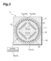
Fig. 3 is a plan view of a photodetecting device. -
Fig. 4 is a plan view of a rotating plate having a toothed gear. -
Fig. 5 is a view showing the arrangement relationship between a light transmitting portion and a scale. -
Fig. 6 is a flowchart showing the processing when an absolute angle of a measurement target is detected by the encoder shown inFig. 1 . -
Fig. 7 are diagrams showing one-dimensional profiles of the light intensity of light to be detected. -
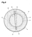
Fig. 8 is a view showing the arrangement relationship between the light transmitting portion and the scale when a positional displacement occurs. -
Fig. 9 is a diagram showing a one-dimensional profile of the light intensity of light to be detected when a displacement occurs. -
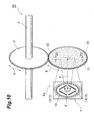
Fig. 10 is a perspective view showing an encoder according to a second embodiment of the present invention. -
Fig. 11 is a perspective view showing an encoder according to a third embodiment of the present invention. -
Fig. 12 is a perspective view showing an optical system of the encoder shown inFig. 11 . -
Fig. 13 is a plan view of a photodetecting device. -
Fig. 14 is a plan view of a slit plate having a toothed gear. -
Fig. 15 is a view showing the arrangement relationship between a slit and a scale. -
Fig. 16 is a flowchart showing the processing when an absolute angle of a measurement target is detected by the encoder shown inFig. 11 . -
Fig. 17 are diagrams showing one-dimensional profiles of the light intensity of light to be detected. -
Fig. 18 is a view showing the arrangement relationship between the slit - and the scale when a positional displacement occurs.
-
Fig. 19 is a diagram showing a one-dimensional profile of the light intensity of light to be detected when a positional displacement occurs. -
Fig. 20 is a plan view of a slit according to a modification. - 1, 3... encoder, 6... LED (light source device), 7... photodetecting device, 8, 31... rotating plate (rotating member) having a toothed gear, 10... PD (photodetecting element), 11... scale plate, 12... output portion, 13...shift register, 17... light transmitting portion, 18... light absorbing film, 19... bright portion, 20... dark portion, 32... light reflecting portion, L1... first arranged line, L2... second arranged line, W1... width of one end side of light transmitting portion, W2... width of the other end side of light transmitting portion, W3... width of one end side of light reflecting portion, W4... width of the other end side of light reflecting portion, 101... encoder, 106... LED (light source device), 107... photodetecting device, 108...slit plate (rotating member) having a toothed gear, 110... PD (photodetecting element), 111... scale plate, 112... output portion, 113... shift register, 117, 120... slit (light transmitting portion), L101... first arranged line, L102... second arranged line, W101... slit width of one end side, W102... slit width of the other end side, X... optical axis
- A preferred embodiment of an encoder and a photodetecting device for an encoder according to the present invention will be described in detail with reference to the drawings.
-
Fig. 1 is a perspective view showing an encoder according to a first embodiment of the present invention. Theencoder 1 shown inFig. 1 is a so-called absolute type rotary encoder, and it is a device for detecting the absolute angle of a measurement target (not shown) such as the handle of a vehicle or the like. Thisencoder 1 is equipped with arotational shaft 2 linked to the measurement target, and adisk 3 having a toothed gear fixed to therotational shaft 2. Thedisk 3 having the toothed gear is rotated in the direction of an arrow A in connection with the rotation of therotational shaft 2 interlocked with the measurement target. -
Fig. 2 is a perspective view showing an optical system S of theencoder 1. As shown inFig. 2 , the optical system S of theencoder 1 is composed of an LED (light source device) 6 being a spot light source for emitting light to be detected, a photodetecting device (photodetecting device for an encoder) 7 that is disposed so as to faceLED 6 and photodetects the light to be detected, a rotating plate (rotating member) 8 having a toothed gear which is engaged with thedisk 3 having the toothed gear, and a pair ofcollimating lens rotating plate 8 having the toothed gear therebetween. - As shown in
Fig. 3 , thephotodetecting device 7 has ascale plate 11 having a plurality of PDs (photodetecting elements) 10 arranged thereon, and anoutput portion 12 for outputting an output signal from eachPD 10. A first arranged line L1 and a second arranged line L2 are concentrically set on thescale plate 11, and therespective PDs 10 are annularly arranged in a zigzag form on the arranged lines L1 and L2. Angle information is allocated to therespective PDs 10 from the first PD 101 (0°) to the last PD 10n (359.5°), for example, at an angular interval of 0.5° in the clockwise direction. Furthermore, by print or the like, alight absorbing film 18 of black resin which contains carbon, for example, is formed in the area on the surface of thescale plate 11 excluding the area wherePDs 10 are arranged. - The
output portion 12 has a plurality of (four in this embodiment) shift registers 13, avideo line 14 and asignal processor 16. Therespective shift registers 13 are arranged in a substantially rectangular form concentrically with thescale plate 11 at the inside of the respective arranged lines L1 and L2, and supply scan signals to therespective PDs 10 for outputting the output signal based on the light intensity of the photodetected light to be detected. Thevideo line 14 is concentrically arranged at the outside of the arranged lines L1 and L2, and outputs an output signal from eachPD 10 to thesignal processor 16. Thesignal processor 16 outputs the output signal received from eachPD 10 via thevideo line 14 to the outside. A supply line (not shown) for a driving signal to eachshift register 13 is connected betweenPD 101 andPD 10n, for example. - On the other hand, as shown in
Fig. 4 , therotating plate 8 having the toothed gear has alight transmitting portion 17 through which a part of the light to be detected emitted fromLED 6 is passed. Thelight transmitting portion 17 is formed of, for example, glass in a straight-line shape so as to pass through the center of therotating plate 8 having the toothed gear. In addition, thelight transmitting portion 17 is formed so that the width is gradually reduced from one end side to the other end side, and the width W1 of one end side is about twice the width W2 of the other end side. Furthermore, alight absorbing film 21 is formed of the same material as thelight absorbing film 18 on the surface of therotating plate 8 having the toothed gear in the area excluding thelight transmitting portion 17. - When the measurement target rotates, the
light transmitting portion 17 is rotated in the direction of an arrow B around the optical axis X of the light to be detected in cooperation between thedisk 3 having the toothed gear and therotating plate 8 having the toothed gear as shown inFig. 1 . The light to be detected that has passed through thelight transmitting portion 17 is designed to have the same straight-line shape as that of thelight transmitting portion 17. Accordingly, as shown inFig. 5 , abright portion 19 to which the light to be detected is irradiated is formed in an area containing mutually separate parts of the arranged lines L1 and L2 of thescale plate 11, that is, a straight-line area containing parts of intersections between the arranged lines L1 and L2 and one end side and the other end side of thelight transmitting portion 17. Furthermore, a part of the light to be detected that has not passed through thelight transmitting portion 17 is absorbed by thelight absorbing film 21. Accordingly, adark portion 20 to which no light to be detected is irradiated is formed in the area of thescale plate 11 excluding thebright portion 19. - In such an optical system S, when the light to be detected is emitted from
LED 6 being a spot light source, the light to be detected is collimated and bundled by thecollimating lens 9A, and then made incident to thelight transmitting portion 17 as shown inFig. 2 . The light to be detected which has passed through thelight transmitting portion 17 and formed into the straight-line shape is converged by thecollimating lens 9B, and one end side and the other end side of the light to be detected are made incident, at two spots, to therespective PDs 10 arranged annularly. The output signal based on the light intensity of the photodetected light to be detected is output from eachPD 10, and output from thesignal processor 16 to the outside. - Next, the processing when the absolute angle of the measurement target is detected by the
encoder 1 having the above construction will be described with reference to the flowchart ofFig. 6 . - First, the output signals obtained from the
respective PDs 10 are collected, and a one-dimensional profile of the light intensity of the light to be detected with respect to therespective PDs 10 is acquired (step S01). At this time, in theencoder 1, the light to be detected that has passed through thelight transmitting portion 17 is made incident, at two spots, to therespective PDs 10 arranged annularly, and thus when the one-dimensional profile is analyzed, two light intensity peaks P1 and P2 that are mutually separated are obtained as shown inFig. 7(a) . In addition, since the width W1 of one end side of thelight transmitting portion 17 is about twice the width W2 of the other end side in theencoder 1, the light intensity peak P1 has a full width at half maximum about twice that of the light intensity peak P2. - Subsequently, the obtained light intensity peaks P1 and P2 are binarized on the basis of a predetermined comparative level (step S02). Thereafter, the
PD 10 corresponding to the center at half maximum of the binarized light intensity peak P1 is set as a reference point to determine the absolute angle, and thePD 10 corresponding to the center at half maximum of the light intensity peak P2 is set as a relative point to determine a relative angle between the light intensity peaks P1 and P2. Then, the angles of the reference point and the relative point are detected on the basis of the angle information allocated to the respective PDs 10 (step S03). - Here, in the
encoder 1, thelight transmitting portion 17 is formed in a straight-line shape. Therefore, when thelight transmitting portion 17 does not have a positional displacement with respect to thescale plate 11, the relative angle (hereinafter, referred to as "reference relative angle") between the reference point and the relative point is uniquely calculated as 180°. On the other hand, when thelight transmitting portion 17 has a positional displacement with respect to thescale plate 11 because of a shaft displacement, a rotational displacement or the like of therotating plate 8 having the toothed gear as shown inFig. 8 , for example, the position of the reference point is displaced by α° with respect to the true position, for example, as shown inFig. 9 . Therefore, the relative angle between the reference point and the relative point on detecting the angle is calculated as 180°+α°. - Therefore, if any difference α° occurs between the reference relative angle and the relative angle on detecting the angle, the α° is calculated as a corrected amount for the angular displacement (step S04). Then, the corrected amount α° is added to (or subtracted from) the angle of the reference point detected in step S03, thereby calculating the absolute angle at the reference point (step S05).
- As described above, in the
encoder 1, the light to be detected is passed through the straight-linelight transmitting portion 17 formed in therotating plate 8 having the toothed gear, whereby thebright portion 19 to which the light to be detected is irradiated is formed in the area containing the mutually separate parts of the arranged lines L1 and L2 on thescale plate 11, and thedark portion 20 to which no light to be detected is irradiated is formed in the area excluding thebright portion 19. Accordingly, the two light intensity peaks P1 and P2 are obtained from the one-dimensional profile of the output signal from thePDs 10, and the absolute angle can be calculated by specifying thePD 10 corresponding to one light intensity peak P1. - On the other hand, the relative angle between the light intensity peaks P1 and P2 (reference relative angle) can be uniquely calculated as 180° based on the shape of the
light transmitting portion 17. Here, if the irradiated position of the light to be detected with respect to thescale plate 11 is displaced from the reference, the relative angle between the light intensity peaks P1 and P2 on detecting the angle is displaced from the reference relative angle by a fixed amount. Therefore, in theencoder 1, even when the irradiated position of the light to be detected with respect to thescale plate 11 is displaced from the reference, the absolute angle of the measurement target can be detected with high accuracy by calculating the deviation amount of the relative angle as a corrected amount α°, and adding/subtracting the corrected amount α° to/from the absolute angle determined by the light intensity peak P1. - Furthermore, in the
encoder 1, thelight transmitting portion 17 has a straight-line shape, and thus a formation thereof is easy and a reduction in the cost of theencoder 1 can be realized. In addition, thelight transmitting portion 17 is formed of glass, and thus it is less likely to be clogged with dust as compared with a case where a slit is used, so that it is possible to suppress a reduction in the detection accuracy of the absolute angle due to level reduction in the output signal, etc., even when theencoder 1 is used for a long time. Furthermore, for thelight transmitting portion 17, the width W1 of one end side thereof is different from the width W2 of the other end side. Therefore, by analyzing the one-dimensional profile of the output signal obtained from therespective PDs 10, the light intensity peaks P1 and P2 having different full widths at half maximum are obtained. Accordingly, the reference point and the relative point can be discriminated from each other, and extensive angle detection across the entire circumference of the scale becomes possible. - On the other hand, only the simple processing of outputting the output signal based on the light intensity of light to be detected made incident to each
PD 10 to the outside is carried out at thephotodetecting device 7 side, and thus the signal processing is rapidly carried out. Furthermore, a frame memory, etc., are not required, and miniaturization of thephotodetecting device 7 and a reduction in the cost can be performed. Still furthermore, in thephotodetecting device 7, therespective shift registers 13 are arranged in the substantially rectangular form so as to be concentric with thescale plate 11 inside the arranged lines L1 and L2. Thephotodetecting device 7 can be further miniaturized by arranging therespective shift registers 13 in an extra space inside the arranged lines L1 and L2. - Furthermore, in the
scale plate 11, therespective PDs 10 are arranged in the zigzag form over the annularly arranged lines L1 and L2. The above arrangement ofPDs 10 can keep thescale plate 11 compact and enhance the resolution of the angle detection. In addition, thelight absorbing film 18 is formed in the area on the surface of thescale plate 11 in the area excluding the area where the PDs 10 are arranged. Accordingly, the effect of multiple reflection of the light to be detected, etc., can be moderated, and the S/N ratio of the one-dimensional profile of the output signal obtained from therespective PDs 10 can be enhanced. - Subsequently, an encoder according to a second embodiment of the present invention will be described. As shown in
Fig. 10 , the difference of anencoder 30 according to the second embodiment from the first embodiment in which the light to be detected is passed through thelight transmitting portion 17 of therotation plate 8 having the toothed gear resides in that light to be detected emitted fromLED 6 is reflected from alight reflecting portion 32 of therotating plate 31 having the toothed gear when thebright portion 19 and thedark portion 20 are formed on thescale plate 11. - That is, in the optical system Sa of the
encoder 30, the rotatingplate 31 having the toothed gear has alight reflecting portion 32 for reflecting a part of the light to be detected emitted fromLED 6. Thelight reflecting portion 32 is formed of, for example, aluminum thin film in a straight-line shape so as to pass through the center of therotating plate 31 having the toothed gear. In addition, thelight reflecting portion 32 is formed, similar to thelight transmitting portion 17 in the first embodiment, so that the width is gradually reduced from one end side to the other end side, and the width W3 of one end side of thelight reflecting portion 32 is about twice the width W4 of the other end side. Furthermore, in therotating plate 31 having the toothed gear, alight absorbing film 33 which is formed of black resin containing carbon, for example, is formed at the portion excluding thelight reflecting portion 32 by print or the like. And,LED 6 is disposed at the center portion of thescale plate 11 in thephotodetecting device 7. - In this
encoder 30, when light to be detected is emitted fromLED 6 to therotating plate 31 having the toothed gear, a straight-line part of the light to be detected which impinges against thelight reflecting portion 32 is reflected to thephotodetecting device 7 side. Accordingly, similar to the first embodiment, thebright portion 19 to which the light to be detected is irradiated is formed in the area containing the mutually separate parts of the arranged lines L1 and L2 in thescale plate 11, that is, the straight-line area containing the parts of intersections between the arranged lines L1 and L2 and one end side and the other end side of the light reflecting portion 32 (seeFig. 5 ). Furthermore, a part of the light to be detected which does not impinge against thelight reflecting portion 32 is absorbed by thelight absorbing film 33. Accordingly, thedark portion 20 to which no light to be detected is irradiated is formed in the area excluding thebright portion 19 of thescale plate 11. The output signal based on the light intensity of the photodetected light to be detected is output from eachPD 10, and then output from thesignal processor 16 to the outside. Accordingly, with thisencoder 30, by analyzing the one-dimensional profile of the output signal of the light to be detected according to the same procedure as the first embodiment, the absolute angle of the measurement target can be detected with high accuracy even when the irradiated position of the light to be detected with respect to thescale plate 11 is displaced from the reference. - Furthermore, in the
encoder 30, the straight-linelight reflecting portion 32 is used to form thebright portion 19 and thedark portion 20, and thus it is unlikely to be clogged with dust as in the case of the first embodiment. Accordingly, even when theencoder 30 is used for a long time, the detection accuracy of the absolute angle can be suppressed from being reduced due to level reduction in the output signal, etc. Furthermore,LED 6 is disposed at thescale plate 11 side, and thus the optical system Sa can be miniaturized. In addition, for thelight reflecting portion 32, the width W3 of one end side is different from the width W4 of the other end side. Therefore, by analyzing the one-dimensional profile of the output signal obtained from therespective PDs 10, the light intensity peaks P1 and P2 having different full widths at half maximum are obtained. Accordingly, the reference point and the relative point can be discriminated from each other, and extensive angle detection across the entire circumference of the scale becomes possible. - The present invention is not limited to the above embodiments. For example, in the
encoder 1 according to the first embodiment, thelight absorbing film 21 is formed in the area excluding thelight transmitting portion 17 in therotating plate 8 having the toothed gear. However, in place of thelight absorbing film 21, a light reflecting film (not shown) may be formed. In this case, the light to be detected which does not pass through thelight transmitting portion 17 is reflected from the light reflecting film to the opposite side of thephotodetecting device 7, so that the S/N ratio of the one-dimensional profile of the output signal obtained from therespective PDs 10 can be enhanced. - In addition, in the
encoder 1 and theencoder 30, the formation pattern of thebright portion 19 and thedark portion 20 to be formed on thescale plate 11 may be inverted. That is, in theencoder 1, a light absorbing film (or light reflecting film) may be formed at the forming position of thelight transmitting portion 17 in therotating plate 8 having the toothed gear, and a light transmitting portion may be formed in the other area. Likewise, in theencoder 30, a light transmitting portion (or light absorbing film) may be formed at the forming position of thelight reflecting portion 32 in therotating plate 31 having the toothed gear, and a light transmitting portion may be formed in the other area. - In this case, a one-dimensional profile of an output signal obtained from the
respective PDs 10 is inverted from that in the case of the above embodiment, however, by carrying out the same processing as the aforementioned step S01 to step S05 based on two bottoms obtained in place of the light intensity peaks P1 and P2, the absolute angle of a measurement target can be detected with high accuracy even when the irradiated position of light to be detected with respect to thescale plate 11 is displaced from a reference. - Subsequently, an encoder according to a third embodiment of the present invention will be described.
-
Fig. 11 is a perspective view showing an embodiment of an encoder according to the present invention. Theencoder 101 shown inFig. 11 is a so-called absolute type rotary encoder, and it is a device for detecting the absolute angle of a measurement target (not shown) such as the handle of a vehicle or the like. Thisencoder 101 is equipped with arotational shaft 102 linked to the measurement target, and adisk 103 having a toothed gear fixed to therotational shaft 102. Thedisk 103 having the toothed gear is rotated in the direction of an arrow A in connection with the rotation of therotational shaft 102 interlocked with the measurement target. -
Fig. 12 is a perspective view showing an optical system Sb of theencoder 101. As shown inFig. 12 , the optical system Sb of theencoder 101 is composed of an LED (light source device) 106 being a spot light source for emitting light to be detected, a photodetecting device (photodetecting device for an encoder) 107 that is disposed so as to faceLED 6 and photodetects the light to be detected, a slit plate (rotating member) 108 having a toothed gear which is engaged with thedisk 103 having the toothed gear, and a pair ofcollimating lens slit plate 108 having the toothed gear therebetween. - As shown in
Fig. 13 , thephotodetecting device 107 has ascale plate 111 having a plurality of PDs (photodetecting elements) 110 arranged thereon, and anoutput portion 112 for outputting an output signal from eachPD 110. A first arranged line L101 and a second arranged line L102 are concentrically set on a rim portion of thescale plate 111, and therespective PDs 110 are annularly arranged in a zigzag form on the arranged lines L101 and L102. Angle information is allocated to therespective PDs 110 from the first PD 1101 (0°) to the last PD 110n (359.5°), for example, at an angular interval of 0.5° in the clockwise direction. - The
output portion 112 has a plurality of (four in this embodiment)shift registers 113, avideo line 114 and asignal processor 116. Therespective shift registers 113 are arranged in a substantially rectangular form concentrically with thescale plate 111 at the inside of the respective arranged lines L101 and L102, and supply scan signals to therespective PDs 110 for outputting the output signal based on the light intensity of the photodetected light to be detected. Thevideo line 114 is concentrically arranged at the outside of the arranged lines L101 and L102, and outputs an output signal from eachPD 110 to thesignal processor 116. Thesignal processor 116 outputs the output signal received from eachPD 110 via thevideo line 114 to the outside. A supply line (not shown) for a driving signal to eachshift register 113 is connected betweenPD 1101 andPD 110n, for example. - On the other hand, as shown in
Fig. 14 , theslit plate 108 having the toothed gear has aslit 117 through which a part of the light to be detected emitted fromLED 106 is passed. Theslit 117 is formed in a straight-line shape so as to pass through the center of theslit plate 108 having the toothed gear. In addition, theslit 117 is formed so that the slit width is gradually reduced from one end side to the other end side, and the slit width W101 of one end side is about twice the slit width W102 of the other end side. - When the measurement target rotates, the
slit 117 is rotated in the direction of an arrow B around the optical axis X of the light to be detected in cooperation between thedisk 103 having the toothed gear and theslit plate 108 having the toothed gear as shown inFig. 11 . The light to be detected that has passed through theslit 117 has the same straight-line shape as the shape of theslit 117, and intersects, as shown inFig. 15 , at two spots of one end side and the other end side different in the slit width from each other, with the respective arranged lines L101 and L102. - In such an optical system Sb, when the light to be detected is emitted from
LED 106 being a spot light source, the light to be detected is collimated and bundled by thecollimating lens 109A, and then made incident to theslit 117 as shown inFig. 12 . The light to be detected which has passed through theslit 117 and formed into the straight-line shape is converged by thecollimating lens 109B, and one end side and the other end side of the light to be detected are made incident, at two spots, to therespective PDs 110 arranged annularly. The output signal based on the light intensity of the photodetected light to be detected is output from eachPD 110, and output from thesignal processor 116 to the outside. - Next, the processing when the absolute angle of the measurement target is detected by the
encoder 101 having the above construction will be described with reference to the flowchart ofFig. 16 . - First, the output signals obtained from the
respective PDs 110 are collected, and a one-dimensional profile of the light intensity of the light to be detected with respect to therespective PDs 110 is acquired (step S101). At this time, in theencoder 101, the light to be detected that has passed through theslit 117 is made incident, at two spots, to therespective PDs 110 arranged annularly, and thus when the one-dimensional profile is analyzed, two light intensity peaks P101 and P102 mutually separated are obtained as shown inFig. 17(a) . In addition, since the slit width W101 of one end side of thelight transmitting portion 17 is about twice the slit width W102 of the other end side in theencoder 101, the light intensity peak P101 has a full width at half maximum about twice that of the light intensity peak P102. - Subsequently, the obtained light intensity peaks P101 and P102 are binarized on the basis of a predetermined comparative level (step S102). Thereafter, the
PD 110 corresponding to the center at half maximum of the binarized light intensity peak P101 is set as a reference point to determine the absolute angle, and thePD 110 corresponding to the center at half maximum of the light intensity peak P102 is set as a relative point to determine a relative angle between the light intensity peaks P101 and P102. Then, the angles of the reference point and the relative point are detected on the basis of the angle information allocated to the respective PDs 110 (step S103). - Here, in the
encoder 101, theslit 117 is formed in a straight-line shape. Therefore, when thelight transmitting portion 117 does not have a positional displacement with respect to thescale plate 111, the relative angle (hereinafter, referred to as "reference relative angle") between the reference point and the relative point is uniquely calculated, as 180°. On the other hand, when thelight transmitting portion 117 has a positional displacement with respect to thescale plate 111 because of a shaft displacement, a rotational displacement or the like of therotating plate 108 having the toothed gear as shown inFig. 18 , for example, the position of the reference point is displaced by α° with respect to the true position, for example, as shown inFig. 19 . Therefore, the relative angle between the reference point and the relative point on detecting the angle is calculated as 180°+α°. - Therefore, if any difference α° occurs between the reference relative angle and the relative angle on detecting the angle, the α° is calculated as a corrected amount for the angular displacement (step S104). Then, the corrected amount α° is added to (or subtracted from) the angle of the reference point detected in step S103, thereby calculating the absolute angle at the reference point (step S 105).
- As described above, in the
encoder 101, the light to be detected that has passed through the straight-line slit 117 is detected at two spots of the plurality ofPDs 110 arranged annularly as a scale. At this time, the reference relative angle between the reference point corresponding to the light intensity peak P101 of the light to be detected and the relative point corresponding to the light intensity peak P102 can be uniquely calculated as 180° based on the shape of the straight-line slit 117. Accordingly, in theencoder 101, even if theslit 117 has a positional displacement with respect to thescale plate 111, the absolute angle of the measurement target can be detected with high accuracy by calculating a corrected amount α° based on the deviation amount of the relative angle between the reference point and relative point on detecting the angle from the reference relative angle. - Furthermore, in the
encoder 101, thelight transmitting portion 117 has a straight-line shape, and thus a formation thereof is easy and a reduction in the cost of theencoder 101 can be realized. Furthermore, for theslit 117, the slit width W101 of one end side is different from theslit width W 102 of the other end side, and thus the light intensity peaks P101 and P102 having different full widths at half maximum are obtained. Accordingly, the reference point and the relative point can be discriminated from each other, and extensive angle detection across the entire circumference of the scale becomes possible. - Furthermore, in the
encoder 101, therespective PDs 110 are arranged in the zigzag form over the annularly arranged lines L101 and L102. The above arrangement ofPDs 110 can keep thescale plate 111 compact and enhance the resolution of the angle detection. - On the other hand, only the simple processing of outputting the output signal based on the light intensity of light to be detected made incident to each
PD 110 to the outside is carried out at thephotodetecting device 107 side, and thus the signal processing is rapidly carried out. Furthermore, a frame memory, etc., are not required, and miniaturization of thephotodetecting device 107 and a reduction in the cost can be performed. Still furthermore, in thephotodetecting device 107, therespective shift registers 113 are arranged in the substantially rectangular form so as to be concentric with thescale plate 111 inside the arranged lines L101 and L102. Thephotodetecting device 107 can be further miniaturized by arranging therespective shift registers 13 in an extra space inside the arranged lines L101 and L102. - The present invention is not limited to the above embodiments. For example, a slit formed in the
slit plate 108 having the toothed gear may have a shape, as in aslit 120 shown inFig. 20 , where one end side and the other end side are separated. In this case, no light to be detected is transmitted from a center part of theslit plate 108 having the toothed gear, and thus the S/N ratio of the light intensity peaks P101 and P102 are enhanced, so that the absolute angle of the measurement target can be detected with a higher accuracy. In addition,photodetecting device 107 may be loaded with an A/D converter so as to make the output signal from eachPD 110 as a digital output. - Here, from a standpoint of detecting the absolute angle with high accuracy, the slit width W101 of one end side of the
slit 117 and the slit width W102 of the other end side may be equal to each other. In this case, the reference point cannot be discriminated from the reference point, so that the angle detection range of theencoder 101 is substantially limited to a range of 180°. Therefore, a gear or the like (not shown) that rotates theslit plate 108 having the toothed gear half round with respect to one round of thedisk 103 having the toothed gear may be interposed. - The following problems to be solved are derived from the third embodiment of the present invention described above.
- That is, an encoder according to the present invention includes: a rotating member having a slit formed thereon; a light source device for emitting light to be detected to the slit; and a photodetecting device including a scale having a plurality of photodetecting elements arranged thereon, and an output portion for outputting an output signal based on the light intensity of the light to be detected made incident to the photodetecting elements after passing through the slit, wherein the photodetecting elements are arranged along an annularly arranged line on the scale, and the light to be detected that has passed through the slit intersects with the arranged line at, at least, two spots mutually separated.
- In the encoder, the light to be detected that has passed through the slit is detected at, at least, two mutually separate spots of the plurality of photodetecting elements arranged annularly as a scale. At this time, by providing either one of the points where the output signal peaks as a reference point to calculate an absolute angle, a relative angle of the reference point from the other point (reference relative angle) can be grasped from the shape of the slit in advance. Here, if the slit has a positional displacement with respect to the scale, a relative angle between the reference point and the other point on detecting the angle is displaced from the reference relative angle by a fixed amount. Therefore, in this encoder, the deviation amount of the relative angle is calculated as a corrected amount, and the corrected amount is added to or subtracted from an absolute angle indicated by the reference point, whereby the absolute angle can be detected with high accuracy even when the slit has a positional displacement with respect to the scale.
- In addition, it is preferable that the slit has a straight-line shape, and an end side and the other end side of the light to be detected that has passed through the slit respectively intersect with the arranged line. It is easy to form the straight line slit, whereby a reduction in the cost of the encoder can be realized
- In addition, it is preferable that, for the slit, the width of one end side is different from the width of the other end side. In this case, since an output signal having different peaks at the reference point and the other point is obtained, the reference point can be discriminated from the other point.
- In addition, it is preferable that the photodetecting elements are arranged in a zigzag form along the arranged line. In this case, the resolution of the angle detection can be enhanced while keeping the scale compact.
- A photodetecting device for an encoder according to the present invention includes: a scale having a plurality of photodetecting elements arranged thereon; and an output portion for outputting an output signal based on light intensity of light to be detected made incident to the photodetecting elements, wherein the photodetecting elements are arranged along an annularly arranged line on the scale.
- The photodetecting device for an encoder includes the plurality of photodetecting elements arranged annularly as a scale. Therefore, by interposing a rotating member having a slit formed thereon between the same and a light source device, it becomes possible to detect the light to be detected that has passed through the slit at, at least, two spots mutually separated. At this time, by providing either one of the points where the output signal peaks as a reference point to calculate an absolute angle, a relative angle of the reference point from the other point (reference relative angle) can be grasped from the shape of the slit in advance. Here, if the slit has a positional displacement with respect to the scale, a relative angle between the reference point and the other point on detecting the angle is displaced from the reference relative angle by a fixed amount. Therefore, in this photodetecting device for an encoder, the deviation amount of the relative angle is calculated as a corrected amount, and the corrected amount is added to or subtracted from an absolute angle indicated by the reference point, whereby the absolute angle can be detected with high accuracy even when the slit has a positional displacement with respect to the scale.
- In addition, it is preferable that the output portion has a shift register that makes the output signal based on light intensity output in sequence from the photodetecting elements, and the shift register is arranged inside the arranged line. It becomes possible to miniaturize the scale by arranging the shift register in an extra space inside the arranged line.
- In addition, it is preferable that the photodetecting elements are arranged in a zigzag form along the arranged line. In this case, the resolution of the angle detection can be enhanced while keeping the scale compact.
Claims (11)
- An encoder comprising:a rotating member;a light source device for emitting light to be detected to the rotating member; anda photodetecting device including a scale having a plurality of photodetecting elements arranged thereon, and an output portion for outputting an output signal based on light intensity of the light to be detected made incident to the photodetecting elements through the rotating member, whereinthe photodetecting elements are arranged along an annularly arranged line on the scale, andthe rotating member is designed so that, in the scale, an area containing mutually separate parts of the arranged line is set as a bright portion to which the light to be detected is irradiated, and an area containing the other portion excluding the parts of the arranged line concerned is set as a dark portion to which no light to be detected is irradiated.
- The encoder according to claim 1, wherein a straight-line light transmitting portion is formed in the rotating member, and
the bright portion is formed of the light to be detected that has passed through the light transmitting portion. - The encoder according to claim 2, wherein for the light transmitting portion, a width of one end side is different from a width of the other end side.
- The encoder according to claim 2, wherein the light transmitting portion is a slit.
- The encoder according to claim 1, wherein a straight-line light reflecting portion is formed in the rotating member, and
the bright portion is formed of the light to be detected reflected from the light reflecting portion. - The encoder according to claim 5, wherein for the light reflecting portion, a width of one end side is different from a width of the other end side.
- The encoder according to claim 1, wherein the photodetecting elements are arranged in a zigzag form along the arranged line.
- The encoder according to claim 1, wherein, in the scale, a light absorbing film is formed in an area excluding the area where the photodetecting elements are arranged.
- A photodetecting device for an encoder comprising:a scale having a plurality of photodetecting elements arranged thereon; andan output portion for outputting an output signal based on light intensity of light to be detected made incident to the photodetecting elements, whereinthe photodetecting elements are arranged along an annularly arranged line on the scale, andin the scale, a light absorbing film is formed in an area excluding the area where the photodetecting elements are arranged.
- The photodetecting device for an encoder according to claim 9, wherein the output portion has a shift register that makes the output signal based on light intensity output in sequence from the photodetecting elements, and
the shift register is arranged inside the arranged line. - The photodetecting device for an encoder according to claim 9, wherein the photodetecting elements are arranged in a zigzag form along the arranged line.
Applications Claiming Priority (2)
| Application Number | Priority Date | Filing Date | Title |
|---|---|---|---|
| JP2005299068 | 2005-10-13 | ||
| PCT/JP2006/320204 WO2007043521A1 (en) | 2005-10-13 | 2006-10-10 | Encoder and light receiving device for encoder |
Publications (2)
| Publication Number | Publication Date |
|---|---|
| EP1936331A1 true EP1936331A1 (en) | 2008-06-25 |
| EP1936331A4 EP1936331A4 (en) | 2015-12-09 |
Family
ID=37942757
Family Applications (1)
| Application Number | Title | Priority Date | Filing Date |
|---|---|---|---|
| EP06811517.9A Withdrawn EP1936331A4 (en) | 2005-10-13 | 2006-10-10 | Encoder and light receiving device for encoder |
Country Status (6)
| Country | Link |
|---|---|
| US (1) | US8044340B2 (en) |
| EP (1) | EP1936331A4 (en) |
| JP (2) | JP5068542B2 (en) |
| KR (1) | KR101240792B1 (en) |
| CN (1) | CN100578155C (en) |
| WO (1) | WO2007043521A1 (en) |
Families Citing this family (8)
| Publication number | Priority date | Publication date | Assignee | Title |
|---|---|---|---|---|
| EP1936331A4 (en) | 2005-10-13 | 2015-12-09 | Hamamatsu Photonics Kk | Encoder and light receiving device for encoder |
| JP4839933B2 (en) * | 2006-04-10 | 2011-12-21 | パナソニック株式会社 | Rotation angle detector |
| JP2008096205A (en) * | 2006-10-10 | 2008-04-24 | Hamamatsu Photonics Kk | Encoder and light receiver for encoder |
| JP4945674B2 (en) * | 2010-11-08 | 2012-06-06 | 株式会社安川電機 | Reflective encoder, servo motor and servo unit |
| JP5950618B2 (en) * | 2012-02-24 | 2016-07-13 | キヤノン株式会社 | Method for forming light transmitting member and method for manufacturing imaging apparatus |
| WO2016150360A1 (en) * | 2015-03-25 | 2016-09-29 | 深圳光启智能光子技术有限公司 | Optical signal reception apparatus |
| JP2019158848A (en) * | 2018-03-16 | 2019-09-19 | 富士電機株式会社 | Absolute location information detection device, and absolute location information detection device control method |
| CN110160644B (en) * | 2018-07-23 | 2024-06-18 | 苏州安必轩微电子技术有限公司 | A real-time light intensity detection device for photoelectric encoder |
Family Cites Families (43)
| Publication number | Priority date | Publication date | Assignee | Title |
|---|---|---|---|---|
| FR2310549A1 (en) * | 1975-05-07 | 1976-12-03 | Sagem | IMPROVEMENTS TO OPTICAL DEVICES FOR DETERMINING THE POSITION OF A MOBILE ORGAN |
| US3983391A (en) * | 1975-05-21 | 1976-09-28 | Itek Corporation | Optical encoder of the reflective type |
| DE3035012C2 (en) | 1980-09-17 | 1982-08-12 | Fa. Carl Zeiss, 7920 Heidenheim | Device for angle measurement |
| US4644157A (en) | 1982-03-08 | 1987-02-17 | Matsushita Electric Industrial Co., Ltd. | Optical rotation detecting apparatus |
| WO1984001027A1 (en) | 1982-09-01 | 1984-03-15 | Rosemount Eng Co Ltd | Position measuring apparatus |
| JPS6047917A (en) | 1983-08-26 | 1985-03-15 | Fuji Electric Corp Res & Dev Ltd | Angle of rotation detector |
| JPS60210718A (en) * | 1984-04-04 | 1985-10-23 | Sumitomo Electric Ind Ltd | Light detection method |
| US4587513A (en) * | 1984-06-25 | 1986-05-06 | Energy Innovations, Inc. | Noncontact shaft angle detector |
| JPS61169703A (en) * | 1985-01-24 | 1986-07-31 | Nissan Motor Co Ltd | Location detecting device |
| JPS61241621A (en) * | 1985-04-19 | 1986-10-27 | Japan Aviation Electronics Ind Ltd | Optical fiber rotary encoder |
| JPS6288917A (en) | 1985-10-16 | 1987-04-23 | Fuji Electric Co Ltd | Rotational position detecting device |
| AT385682B (en) | 1985-11-08 | 1988-05-10 | Voest Alpine Ag | METHOD FOR SEPARATING GAS MIXTURES, AND APPARATUS FOR CARRYING OUT THIS METHOD |
| US4827123A (en) * | 1986-04-11 | 1989-05-02 | Sangamo Weston, Inc. | Direction sensitive optical shaft encoder |
| JPS636417A (en) * | 1986-06-27 | 1988-01-12 | Fuji Electric Co Ltd | Rotational position detecting device |
| JPH01196514A (en) | 1988-02-01 | 1989-08-08 | Fuji Electric Co Ltd | Photoelectric conversion type rotary position detector |
| US4906992A (en) | 1988-02-22 | 1990-03-06 | Dynamics Research Corporation | Single track absolute encoder |
| US4947166A (en) | 1988-02-22 | 1990-08-07 | Dynamics Research Corporation | Single track absolute encoder |
| JP2586121B2 (en) * | 1988-09-30 | 1997-02-26 | キヤノン株式会社 | Rotary encoder origin detection system |
| US5274476A (en) * | 1991-08-14 | 1993-12-28 | Gold Star Electron Co., Ltd. | CCD image sensor with photodiodes in a zig-zag pattern and particular transfer gate electrodes formed over channel stop regions and VCCD regions |
| JPH0810145A (en) | 1994-06-28 | 1996-01-16 | Matsushita Electric Ind Co Ltd | rice cooker |
| US5642297A (en) * | 1994-12-12 | 1997-06-24 | Gurley Precision Instruments, Inc. | Apparatus and method for measuring the kinematic accuracy in machines and mechanisms using absolute encoders |
| US5640007A (en) | 1995-06-21 | 1997-06-17 | Limitorque Corporation | Optical encoder comprising a plurality of encoder wheels |
| JP3631551B2 (en) * | 1996-01-23 | 2005-03-23 | 株式会社ミツトヨ | Optical encoder |
| JP3684281B2 (en) * | 1996-10-18 | 2005-08-17 | 日本電産コパル株式会社 | Optical encoder |
| JP4182299B2 (en) * | 1997-11-14 | 2008-11-19 | 株式会社安川電機 | Optical encoder and method for attaching fixed side element of optical encoder |
| US6127676A (en) | 1998-02-20 | 2000-10-03 | Tseng; Hsin Te | Photo sensing device with means to eliminate light beam interference |
| JP3659029B2 (en) * | 1998-11-04 | 2005-06-15 | 富士電機機器制御株式会社 | Absolute encoder |
| JP4981203B2 (en) | 2000-08-01 | 2012-07-18 | オリンパス株式会社 | Optical encoder |
| US6713756B2 (en) | 2000-05-09 | 2004-03-30 | Olympus Corporation | Optical encoder and optical rotary encoder |
| JP2002139353A (en) * | 2000-11-06 | 2002-05-17 | Olympus Optical Co Ltd | Optical rotary encoder |
| JP3737037B2 (en) | 2001-05-31 | 2006-01-18 | ニスカ株式会社 | Printing device |
| JP2003315101A (en) | 2002-04-22 | 2003-11-06 | Olympus Optical Co Ltd | Optical encoder |
| US7183537B2 (en) * | 2002-12-16 | 2007-02-27 | Gsi Group Corporation | Rotary position sensor with offset beam generating element and elliptical detector array |
| DE10308440A1 (en) * | 2003-02-27 | 2004-09-16 | Stegmann Gmbh & Co. Kg | Device for measuring the angle of rotation |
| JP4307895B2 (en) | 2003-04-17 | 2009-08-05 | 三洋電機株式会社 | Optical encoder |
| JP2005121612A (en) * | 2003-10-20 | 2005-05-12 | Hamamatsu Photonics Kk | Absolute encoder and angle detecting method |
| US7265336B2 (en) * | 2003-12-01 | 2007-09-04 | Avago Technologies Ecbu Ip (Singapore) Pte. Ltd. | Encoder utilizing a reflective cylindrical surface |
| JP2006119082A (en) | 2004-10-25 | 2006-05-11 | Hitachi Cable Ltd | Steering angle detector |
| EP1936331A4 (en) | 2005-10-13 | 2015-12-09 | Hamamatsu Photonics Kk | Encoder and light receiving device for encoder |
| US7784694B2 (en) | 2005-11-21 | 2010-08-31 | Avago Technologies General Ip (Singapore) Pte. Ltd. | Reflective encoder with lens on code strip |
| JP2008096205A (en) | 2006-10-10 | 2008-04-24 | Hamamatsu Photonics Kk | Encoder and light receiver for encoder |
| JP4890190B2 (en) | 2006-10-10 | 2012-03-07 | 浜松ホトニクス株式会社 | Encoder |
| US7608813B1 (en) | 2008-11-18 | 2009-10-27 | Mitutoyo Corporation | Scale track configuration for absolute optical encoder including a detector electronics with plurality of track detector portions |
-
2006
- 2006-10-10 EP EP06811517.9A patent/EP1936331A4/en not_active Withdrawn
- 2006-10-10 JP JP2006553382A patent/JP5068542B2/en active Active
- 2006-10-10 US US11/883,070 patent/US8044340B2/en active Active
- 2006-10-10 WO PCT/JP2006/320204 patent/WO2007043521A1/en not_active Ceased
- 2006-10-10 KR KR1020077020404A patent/KR101240792B1/en active Active
- 2006-10-10 CN CN200680015493A patent/CN100578155C/en active Active
-
2012
- 2012-05-30 JP JP2012123172A patent/JP5335970B2/en active Active
Non-Patent Citations (1)
| Title |
|---|
| See references of WO2007043521A1 * |
Also Published As
| Publication number | Publication date |
|---|---|
| KR101240792B1 (en) | 2013-03-07 |
| JP5068542B2 (en) | 2012-11-07 |
| US20080185505A1 (en) | 2008-08-07 |
| US8044340B2 (en) | 2011-10-25 |
| JP2012185175A (en) | 2012-09-27 |
| EP1936331A4 (en) | 2015-12-09 |
| JPWO2007043521A1 (en) | 2009-04-16 |
| CN100578155C (en) | 2010-01-06 |
| JP5335970B2 (en) | 2013-11-06 |
| KR20080056111A (en) | 2008-06-20 |
| WO2007043521A1 (en) | 2007-04-19 |
| CN101171498A (en) | 2008-04-30 |
Similar Documents
| Publication | Publication Date | Title |
|---|---|---|
| JP5335970B2 (en) | Encoder | |
| US6240652B1 (en) | Optoelectronical position detection | |
| JP6407502B1 (en) | Absolute encoder | |
| US10094684B2 (en) | Method of manufacturing rotary scale, rotary scale, rotary encoder, driving apparatus, image pickup apparatus and robot apparatus | |
| JPH0914941A (en) | Rotation angle detection device | |
| KR20090074725A (en) | Encoder | |
| US20070181790A1 (en) | Reflective encoder with reduced background noise | |
| JP3683375B2 (en) | Rotary encoder | |
| JP2008096205A (en) | Encoder and light receiver for encoder | |
| JP3448658B2 (en) | Multiplex detection method and multiple detection device for photoelectron signal | |
| US6818884B2 (en) | Optoelectronic sensor having transparent cover shaped as light deflecting element | |
| EP1795872B2 (en) | Photoelectric rotary encoder | |
| US20070120048A1 (en) | Reflective encoder module | |
| JPS6381212A (en) | rotary encoder | |
| JP2002139353A (en) | Optical rotary encoder | |
| JPH1123321A (en) | Optical scale and displacement information measuring device using the same | |
| JPH1079836A (en) | Image reading device | |
| JPH05118879A (en) | Position detection device | |
| JP2000121388A (en) | Optical encoder | |
| JP2692611B2 (en) | Multi-element imaging device | |
| JPH0715376B2 (en) | Rotation angle detector | |
| JPH1051628A (en) | Image reading device | |
| JPH1075331A (en) | Image reading device | |
| JPH0399220A (en) | Encoder | |
| JPH11205554A (en) | Handy scanner |
Legal Events
| Date | Code | Title | Description |
|---|---|---|---|
| PUAI | Public reference made under article 153(3) epc to a published international application that has entered the european phase |
Free format text: ORIGINAL CODE: 0009012 |
|
| 17P | Request for examination filed |
Effective date: 20070718 |
|
| AK | Designated contracting states |
Kind code of ref document: A1 Designated state(s): DE FR GB |
|
| RBV | Designated contracting states (corrected) |
Designated state(s): DE FR GB |
|
| DAX | Request for extension of the european patent (deleted) | ||
| RBV | Designated contracting states (corrected) |
Designated state(s): DE FR GB |
|
| RIC1 | Information provided on ipc code assigned before grant |
Ipc: G01D 5/347 20060101AFI20150615BHEP |
|
| RIC1 | Information provided on ipc code assigned before grant |
Ipc: G01D 5/347 20060101AFI20151007BHEP |
|
| RIC1 | Information provided on ipc code assigned before grant |
Ipc: G01D 5/347 20060101AFI20151012BHEP |
|
| RA4 | Supplementary search report drawn up and despatched (corrected) |
Effective date: 20151106 |
|
| RIC1 | Information provided on ipc code assigned before grant |
Ipc: G01D 5/347 20060101AFI20151030BHEP |
|
| 17Q | First examination report despatched |
Effective date: 20151127 |
|
| STAA | Information on the status of an ep patent application or granted ep patent |
Free format text: STATUS: THE APPLICATION IS DEEMED TO BE WITHDRAWN |
|
| 18D | Application deemed to be withdrawn |
Effective date: 20160408 |