EP1935844A1 - Hydrogen supply apparatus and fuel gas supply apparatus - Google Patents
Hydrogen supply apparatus and fuel gas supply apparatus Download PDFInfo
- Publication number
- EP1935844A1 EP1935844A1 EP06783199A EP06783199A EP1935844A1 EP 1935844 A1 EP1935844 A1 EP 1935844A1 EP 06783199 A EP06783199 A EP 06783199A EP 06783199 A EP06783199 A EP 06783199A EP 1935844 A1 EP1935844 A1 EP 1935844A1
- Authority
- EP
- European Patent Office
- Prior art keywords
- temperature
- gas
- odorant
- hydrogen gas
- hydrogen
- Prior art date
- Legal status (The legal status is an assumption and is not a legal conclusion. Google has not performed a legal analysis and makes no representation as to the accuracy of the status listed.)
- Granted
Links
Images




Classifications
-
- H—ELECTRICITY
- H01—ELECTRIC ELEMENTS
- H01M—PROCESSES OR MEANS, e.g. BATTERIES, FOR THE DIRECT CONVERSION OF CHEMICAL ENERGY INTO ELECTRICAL ENERGY
- H01M8/00—Fuel cells; Manufacture thereof
- H01M8/04—Auxiliary arrangements, e.g. for control of pressure or for circulation of fluids
- H01M8/04082—Arrangements for control of reactant parameters, e.g. pressure or concentration
- H01M8/04201—Reactant storage and supply, e.g. means for feeding, pipes
-
- C—CHEMISTRY; METALLURGY
- C01—INORGANIC CHEMISTRY
- C01B—NON-METALLIC ELEMENTS; COMPOUNDS THEREOF; METALLOIDS OR COMPOUNDS THEREOF NOT COVERED BY SUBCLASS C01C
- C01B3/00—Hydrogen; Gaseous mixtures containing hydrogen; Separation of hydrogen from mixtures containing it; Purification of hydrogen; Reversible storage of hydrogen
-
- F—MECHANICAL ENGINEERING; LIGHTING; HEATING; WEAPONS; BLASTING
- F17—STORING OR DISTRIBUTING GASES OR LIQUIDS
- F17C—VESSELS FOR CONTAINING OR STORING COMPRESSED, LIQUEFIED OR SOLIDIFIED GASES; FIXED-CAPACITY GAS-HOLDERS; FILLING VESSELS WITH, OR DISCHARGING FROM VESSELS, COMPRESSED, LIQUEFIED, OR SOLIDIFIED GASES
- F17C7/00—Methods or apparatus for discharging liquefied, solidified, or compressed gases from pressure vessels, not covered by another subclass
-
- H—ELECTRICITY
- H01—ELECTRIC ELEMENTS
- H01M—PROCESSES OR MEANS, e.g. BATTERIES, FOR THE DIRECT CONVERSION OF CHEMICAL ENERGY INTO ELECTRICAL ENERGY
- H01M8/00—Fuel cells; Manufacture thereof
- H01M8/04—Auxiliary arrangements, e.g. for control of pressure or for circulation of fluids
- H01M8/04082—Arrangements for control of reactant parameters, e.g. pressure or concentration
- H01M8/04089—Arrangements for control of reactant parameters, e.g. pressure or concentration of gaseous reactants
-
- F—MECHANICAL ENGINEERING; LIGHTING; HEATING; WEAPONS; BLASTING
- F17—STORING OR DISTRIBUTING GASES OR LIQUIDS
- F17C—VESSELS FOR CONTAINING OR STORING COMPRESSED, LIQUEFIED OR SOLIDIFIED GASES; FIXED-CAPACITY GAS-HOLDERS; FILLING VESSELS WITH, OR DISCHARGING FROM VESSELS, COMPRESSED, LIQUEFIED, OR SOLIDIFIED GASES
- F17C2221/00—Handled fluid, in particular type of fluid
- F17C2221/01—Pure fluids
- F17C2221/012—Hydrogen
-
- F—MECHANICAL ENGINEERING; LIGHTING; HEATING; WEAPONS; BLASTING
- F17—STORING OR DISTRIBUTING GASES OR LIQUIDS
- F17C—VESSELS FOR CONTAINING OR STORING COMPRESSED, LIQUEFIED OR SOLIDIFIED GASES; FIXED-CAPACITY GAS-HOLDERS; FILLING VESSELS WITH, OR DISCHARGING FROM VESSELS, COMPRESSED, LIQUEFIED, OR SOLIDIFIED GASES
- F17C2223/00—Handled fluid before transfer, i.e. state of fluid when stored in the vessel or before transfer from the vessel
- F17C2223/01—Handled fluid before transfer, i.e. state of fluid when stored in the vessel or before transfer from the vessel characterised by the phase
- F17C2223/0107—Single phase
- F17C2223/0123—Single phase gaseous, e.g. CNG, GNC
-
- F—MECHANICAL ENGINEERING; LIGHTING; HEATING; WEAPONS; BLASTING
- F17—STORING OR DISTRIBUTING GASES OR LIQUIDS
- F17C—VESSELS FOR CONTAINING OR STORING COMPRESSED, LIQUEFIED OR SOLIDIFIED GASES; FIXED-CAPACITY GAS-HOLDERS; FILLING VESSELS WITH, OR DISCHARGING FROM VESSELS, COMPRESSED, LIQUEFIED, OR SOLIDIFIED GASES
- F17C2223/00—Handled fluid before transfer, i.e. state of fluid when stored in the vessel or before transfer from the vessel
- F17C2223/03—Handled fluid before transfer, i.e. state of fluid when stored in the vessel or before transfer from the vessel characterised by the pressure level
- F17C2223/036—Very high pressure (>80 bar)
-
- F—MECHANICAL ENGINEERING; LIGHTING; HEATING; WEAPONS; BLASTING
- F17—STORING OR DISTRIBUTING GASES OR LIQUIDS
- F17C—VESSELS FOR CONTAINING OR STORING COMPRESSED, LIQUEFIED OR SOLIDIFIED GASES; FIXED-CAPACITY GAS-HOLDERS; FILLING VESSELS WITH, OR DISCHARGING FROM VESSELS, COMPRESSED, LIQUEFIED, OR SOLIDIFIED GASES
- F17C2225/00—Handled fluid after transfer, i.e. state of fluid after transfer from the vessel
- F17C2225/01—Handled fluid after transfer, i.e. state of fluid after transfer from the vessel characterised by the phase
- F17C2225/0107—Single phase
- F17C2225/0123—Single phase gaseous, e.g. CNG, GNC
-
- F—MECHANICAL ENGINEERING; LIGHTING; HEATING; WEAPONS; BLASTING
- F17—STORING OR DISTRIBUTING GASES OR LIQUIDS
- F17C—VESSELS FOR CONTAINING OR STORING COMPRESSED, LIQUEFIED OR SOLIDIFIED GASES; FIXED-CAPACITY GAS-HOLDERS; FILLING VESSELS WITH, OR DISCHARGING FROM VESSELS, COMPRESSED, LIQUEFIED, OR SOLIDIFIED GASES
- F17C2225/00—Handled fluid after transfer, i.e. state of fluid after transfer from the vessel
- F17C2225/03—Handled fluid after transfer, i.e. state of fluid after transfer from the vessel characterised by the pressure level
- F17C2225/036—Very high pressure, i.e. above 80 bars
-
- F—MECHANICAL ENGINEERING; LIGHTING; HEATING; WEAPONS; BLASTING
- F17—STORING OR DISTRIBUTING GASES OR LIQUIDS
- F17C—VESSELS FOR CONTAINING OR STORING COMPRESSED, LIQUEFIED OR SOLIDIFIED GASES; FIXED-CAPACITY GAS-HOLDERS; FILLING VESSELS WITH, OR DISCHARGING FROM VESSELS, COMPRESSED, LIQUEFIED, OR SOLIDIFIED GASES
- F17C2227/00—Transfer of fluids, i.e. method or means for transferring the fluid; Heat exchange with the fluid
- F17C2227/03—Heat exchange with the fluid
- F17C2227/0302—Heat exchange with the fluid by heating
- F17C2227/0304—Heat exchange with the fluid by heating using an electric heater
-
- F—MECHANICAL ENGINEERING; LIGHTING; HEATING; WEAPONS; BLASTING
- F17—STORING OR DISTRIBUTING GASES OR LIQUIDS
- F17C—VESSELS FOR CONTAINING OR STORING COMPRESSED, LIQUEFIED OR SOLIDIFIED GASES; FIXED-CAPACITY GAS-HOLDERS; FILLING VESSELS WITH, OR DISCHARGING FROM VESSELS, COMPRESSED, LIQUEFIED, OR SOLIDIFIED GASES
- F17C2227/00—Transfer of fluids, i.e. method or means for transferring the fluid; Heat exchange with the fluid
- F17C2227/03—Heat exchange with the fluid
- F17C2227/0367—Localisation of heat exchange
- F17C2227/0369—Localisation of heat exchange in or on a vessel
-
- F—MECHANICAL ENGINEERING; LIGHTING; HEATING; WEAPONS; BLASTING
- F17—STORING OR DISTRIBUTING GASES OR LIQUIDS
- F17C—VESSELS FOR CONTAINING OR STORING COMPRESSED, LIQUEFIED OR SOLIDIFIED GASES; FIXED-CAPACITY GAS-HOLDERS; FILLING VESSELS WITH, OR DISCHARGING FROM VESSELS, COMPRESSED, LIQUEFIED, OR SOLIDIFIED GASES
- F17C2227/00—Transfer of fluids, i.e. method or means for transferring the fluid; Heat exchange with the fluid
- F17C2227/03—Heat exchange with the fluid
- F17C2227/0367—Localisation of heat exchange
- F17C2227/0388—Localisation of heat exchange separate
-
- F—MECHANICAL ENGINEERING; LIGHTING; HEATING; WEAPONS; BLASTING
- F17—STORING OR DISTRIBUTING GASES OR LIQUIDS
- F17C—VESSELS FOR CONTAINING OR STORING COMPRESSED, LIQUEFIED OR SOLIDIFIED GASES; FIXED-CAPACITY GAS-HOLDERS; FILLING VESSELS WITH, OR DISCHARGING FROM VESSELS, COMPRESSED, LIQUEFIED, OR SOLIDIFIED GASES
- F17C2250/00—Accessories; Control means; Indicating, measuring or monitoring of parameters
- F17C2250/03—Control means
- F17C2250/032—Control means using computers
-
- F—MECHANICAL ENGINEERING; LIGHTING; HEATING; WEAPONS; BLASTING
- F17—STORING OR DISTRIBUTING GASES OR LIQUIDS
- F17C—VESSELS FOR CONTAINING OR STORING COMPRESSED, LIQUEFIED OR SOLIDIFIED GASES; FIXED-CAPACITY GAS-HOLDERS; FILLING VESSELS WITH, OR DISCHARGING FROM VESSELS, COMPRESSED, LIQUEFIED, OR SOLIDIFIED GASES
- F17C2250/00—Accessories; Control means; Indicating, measuring or monitoring of parameters
- F17C2250/04—Indicating or measuring of parameters as input values
- F17C2250/0404—Parameters indicated or measured
- F17C2250/0439—Temperature
-
- F—MECHANICAL ENGINEERING; LIGHTING; HEATING; WEAPONS; BLASTING
- F17—STORING OR DISTRIBUTING GASES OR LIQUIDS
- F17C—VESSELS FOR CONTAINING OR STORING COMPRESSED, LIQUEFIED OR SOLIDIFIED GASES; FIXED-CAPACITY GAS-HOLDERS; FILLING VESSELS WITH, OR DISCHARGING FROM VESSELS, COMPRESSED, LIQUEFIED, OR SOLIDIFIED GASES
- F17C2260/00—Purposes of gas storage and gas handling
- F17C2260/03—Dealing with losses
- F17C2260/035—Dealing with losses of fluid
- F17C2260/036—Avoiding leaks
-
- F—MECHANICAL ENGINEERING; LIGHTING; HEATING; WEAPONS; BLASTING
- F17—STORING OR DISTRIBUTING GASES OR LIQUIDS
- F17C—VESSELS FOR CONTAINING OR STORING COMPRESSED, LIQUEFIED OR SOLIDIFIED GASES; FIXED-CAPACITY GAS-HOLDERS; FILLING VESSELS WITH, OR DISCHARGING FROM VESSELS, COMPRESSED, LIQUEFIED, OR SOLIDIFIED GASES
- F17C2265/00—Effects achieved by gas storage or gas handling
- F17C2265/02—Mixing fluids
- F17C2265/025—Mixing fluids different fluids
- F17C2265/027—Mixing fluids different fluids with odorizing
-
- F—MECHANICAL ENGINEERING; LIGHTING; HEATING; WEAPONS; BLASTING
- F17—STORING OR DISTRIBUTING GASES OR LIQUIDS
- F17C—VESSELS FOR CONTAINING OR STORING COMPRESSED, LIQUEFIED OR SOLIDIFIED GASES; FIXED-CAPACITY GAS-HOLDERS; FILLING VESSELS WITH, OR DISCHARGING FROM VESSELS, COMPRESSED, LIQUEFIED, OR SOLIDIFIED GASES
- F17C2270/00—Applications
- F17C2270/01—Applications for fluid transport or storage
- F17C2270/0165—Applications for fluid transport or storage on the road
- F17C2270/0184—Fuel cells
-
- H—ELECTRICITY
- H01—ELECTRIC ELEMENTS
- H01M—PROCESSES OR MEANS, e.g. BATTERIES, FOR THE DIRECT CONVERSION OF CHEMICAL ENERGY INTO ELECTRICAL ENERGY
- H01M8/00—Fuel cells; Manufacture thereof
- H01M8/04—Auxiliary arrangements, e.g. for control of pressure or for circulation of fluids
- H01M8/04082—Arrangements for control of reactant parameters, e.g. pressure or concentration
- H01M8/04089—Arrangements for control of reactant parameters, e.g. pressure or concentration of gaseous reactants
- H01M8/04097—Arrangements for control of reactant parameters, e.g. pressure or concentration of gaseous reactants with recycling of the reactants
-
- Y—GENERAL TAGGING OF NEW TECHNOLOGICAL DEVELOPMENTS; GENERAL TAGGING OF CROSS-SECTIONAL TECHNOLOGIES SPANNING OVER SEVERAL SECTIONS OF THE IPC; TECHNICAL SUBJECTS COVERED BY FORMER USPC CROSS-REFERENCE ART COLLECTIONS [XRACs] AND DIGESTS
- Y02—TECHNOLOGIES OR APPLICATIONS FOR MITIGATION OR ADAPTATION AGAINST CLIMATE CHANGE
- Y02E—REDUCTION OF GREENHOUSE GAS [GHG] EMISSIONS, RELATED TO ENERGY GENERATION, TRANSMISSION OR DISTRIBUTION
- Y02E60/00—Enabling technologies; Technologies with a potential or indirect contribution to GHG emissions mitigation
- Y02E60/30—Hydrogen technology
- Y02E60/32—Hydrogen storage
-
- Y—GENERAL TAGGING OF NEW TECHNOLOGICAL DEVELOPMENTS; GENERAL TAGGING OF CROSS-SECTIONAL TECHNOLOGIES SPANNING OVER SEVERAL SECTIONS OF THE IPC; TECHNICAL SUBJECTS COVERED BY FORMER USPC CROSS-REFERENCE ART COLLECTIONS [XRACs] AND DIGESTS
- Y02—TECHNOLOGIES OR APPLICATIONS FOR MITIGATION OR ADAPTATION AGAINST CLIMATE CHANGE
- Y02E—REDUCTION OF GREENHOUSE GAS [GHG] EMISSIONS, RELATED TO ENERGY GENERATION, TRANSMISSION OR DISTRIBUTION
- Y02E60/00—Enabling technologies; Technologies with a potential or indirect contribution to GHG emissions mitigation
- Y02E60/30—Hydrogen technology
- Y02E60/50—Fuel cells
-
- Y—GENERAL TAGGING OF NEW TECHNOLOGICAL DEVELOPMENTS; GENERAL TAGGING OF CROSS-SECTIONAL TECHNOLOGIES SPANNING OVER SEVERAL SECTIONS OF THE IPC; TECHNICAL SUBJECTS COVERED BY FORMER USPC CROSS-REFERENCE ART COLLECTIONS [XRACs] AND DIGESTS
- Y02—TECHNOLOGIES OR APPLICATIONS FOR MITIGATION OR ADAPTATION AGAINST CLIMATE CHANGE
- Y02P—CLIMATE CHANGE MITIGATION TECHNOLOGIES IN THE PRODUCTION OR PROCESSING OF GOODS
- Y02P90/00—Enabling technologies with a potential contribution to greenhouse gas [GHG] emissions mitigation
- Y02P90/45—Hydrogen technologies in production processes
-
- Y—GENERAL TAGGING OF NEW TECHNOLOGICAL DEVELOPMENTS; GENERAL TAGGING OF CROSS-SECTIONAL TECHNOLOGIES SPANNING OVER SEVERAL SECTIONS OF THE IPC; TECHNICAL SUBJECTS COVERED BY FORMER USPC CROSS-REFERENCE ART COLLECTIONS [XRACs] AND DIGESTS
- Y10—TECHNICAL SUBJECTS COVERED BY FORMER USPC
- Y10T—TECHNICAL SUBJECTS COVERED BY FORMER US CLASSIFICATION
- Y10T137/00—Fluid handling
- Y10T137/6416—With heating or cooling of the system
-
- Y—GENERAL TAGGING OF NEW TECHNOLOGICAL DEVELOPMENTS; GENERAL TAGGING OF CROSS-SECTIONAL TECHNOLOGIES SPANNING OVER SEVERAL SECTIONS OF THE IPC; TECHNICAL SUBJECTS COVERED BY FORMER USPC CROSS-REFERENCE ART COLLECTIONS [XRACs] AND DIGESTS
- Y10—TECHNICAL SUBJECTS COVERED BY FORMER USPC
- Y10T—TECHNICAL SUBJECTS COVERED BY FORMER US CLASSIFICATION
- Y10T137/00—Fluid handling
- Y10T137/6416—With heating or cooling of the system
- Y10T137/6606—With electric heating element
Definitions
- the present invention relates to a hydrogen supply apparatus and a fuel gas supply apparatuses, each of which can be suitably used in a fuel cell system that generates electric energy by an electrochemical reaction in particular.
- a fuel cell system for obtaining electric energy by an electrochemical reaction between a hydrogen gas and an oxidation gas is known.
- the hydrogen gas serving as a fuel for this fuel cell system is flammable and odorless.
- the odorant and the hydrogen gas In order to detect the leakage of the hydrogen gas, the odorant and the hydrogen gas have to be mixed. However, in the case where the hydrogen gas has reached an extremely low temperature, the odorant has sometimes been solidified, and the hydrogen gas and the odorant have not been mixed at an extremely low temperature in some cases. In a system for storing the hydrogen gas in a high-pressure state, such as a high-pressure hydrogen tank in particular, the hydrogen gas has reached an extremely low temperature due to adiabatic expansion during the hydrogen supply, and the hydrogen gas has been supplied while not being mixed with the odorant in some cases.
- the present invention has been made in view of the various problems mentioned above, and it is an object of the present invention to provide a hydrogen supply apparatus capable of mixing an odorant with a hydrogen gas even at a low temperature, and detecting the hydrogen gas leakage.
- a hydrogen supply apparatus includes: gas storage means for storing a hydrogen gas; odorant addition means for adding an odorant to the hydrogen gas; and temperature adjustment means for adjusting a temperature of at least one of the hydrogen gas, the odorant, and the hydrogen gas to which the odorant has been added.
- the hydrogen supply apparatus upon supply of the hydrogen gas stored in the gas storage means to the outside thereof, the pressure of the hydrogen gas is reduced, and the hydrogen gas undergoes adiabatic expansion. Thus, the temperature of the hydrogen gas is reduced.
- the temperature of the hydrogen gas is reduced to a level equal to or lower than a predetermined temperature, the odorant to be mixed with the hydrogen gas is solidified or liquefied, and may have difficulty in mixing with the hydrogen gas.
- the hydrogen supply apparatus increases the temperature of at least one of the hydrogen gas and the odorant by the temperature adjustment means to suppress a temperature reduction in hydrogen gas, thus making it possible to maintain the odorant in a state in which (or at a temperature at which) the odorant can be mixed with the hydrogen gas.
- the hydrogen gas whose temperature is increased may be a hydrogen gas stored in the gas storage means, or may be a hydrogen gas supplied to the outside from the gas storage means. Further, the hydrogen gas supplied to the outside includes a hydrogen gas to which the odorant has been added. It should be noted that the hydrogen gas supply apparatus according to the present invention can add the odorant to the hydrogen gas by including odorant addition means.
- the hydrogen gas to which the odorant is to be added may be a hydrogen gas stored in the gas storage means, or may be a hydrogen gas discharged from the gas storage means. Further, the hydrogen gas, to which the odorant has been added by the odorant addition means, is supplied to the supply destination for the hydrogen gas, i.e., a hydrogen gas utilization apparatus such as a fuel cell or a hydrogen engine.
- a hydrogen gas utilization apparatus such as a fuel cell or a hydrogen engine.
- a hydrogen supply apparatus may be characterized by further including stored gas temperature detection means for detecting the temperature of the hydrogen gas stored in the gas storage means, and characterized in that the temperature adjustment means has gas temperature reduction suppression means for suppressing a temperature reduction in hydrogen gas stored in the gas storage means, when the temperature of the hydrogen gas detected by the stored gas temperature detection means is equal to or lower than a predetermined temperature.
- the predetermined temperature refers to a temperature below which the odorant is changed into, for example, a solid form incapable of mixing with the hydrogen gas, and is appropriately set in accordance with the properties of the odorant.
- a hydrogen supply apparatus may be characterized by further including hydrogen gas temperature detection means for detecting the temperature of the hydrogen gas supplied from the gas storage means, and characterized in that the temperature adjustment means has heating means for increasing the temperature of the hydrogen gas supplied from the gas storage means, when the temperature of the hydrogen gas detected by the hydrogen gas temperature detection means is equal to or lower than a predetermined temperature.
- the above-mentioned stored gas temperature detection means detects the temperature of the hydrogen gas stored in the gas storage means; on the other hand, the hydrogen gas temperature detection means detects the temperature of the hydrogen gas, supplied to the outside of the gas storage means, at the outside of the gas storage means. That is, the hydrogen gas temperature detection means is capable of detecting the temperature of the hydrogen gas to be supplied to the outside of the gas storage means, which has been reduced due to adiabatic expansion. Based on the temperature of the hydrogen gas detected, the temperature adjustment means increases the temperature of the hydrogen gas supplied from the gas storage means, thereby making it possible to suppress the liquefaction or solidification of the odorant, resulting from the cooling thereof by the hydrogen whose temperature has been reduced. It should be noted that the heating means may be any means as long as it is capable of increasing the temperature of the hydrogen gas, and an example of which may be a heater.
- the hydrogen supply apparatus may be characterized by further including an odorant temperature detection means for detecting the temperature of the odorant to be added by the odorant addition means, in which the temperature adjustment means has heating means for increasing the temperature of the odorant to be added by the odorant addition means, when the temperature of the odorant detected by the odorant temperature detection means is equal to or lower than a predetermined temperature.
- the necessary vapor pressure refers to a pressure at which the odorant added to the hydrogen gas does not liquefy or solidify.
- the supply of heat to the odorant may be carried out by providing an odorant storage means for storing an odorant, for example, and by raising the temperature of the odorant storage means using heating means such as a heater. By adjusting the vapor pressure of the odorant in this manner, the liquefaction or solidification of the odorant can be suppressed.
- the heating means may be any means as long as it can increase the temperature of the odorant, and an example of which may be a heater.
- the hydrogen supply apparatus may be characterized by further including: hydrogen gas temperature detection means for detecting the temperature of the hydrogen gas supplied from the gas storage means; and odorant temperature detection means for detecting the temperature of the odorant added by the odorant addition means, in which the temperature adjustment means has heating means for increasing the temperature of the odorant when at least one of the temperature of the hydrogen gas detected by the hydrogen gas temperature detection means and the temperature of the odorant detected by the odorant temperature detection means meets a predetermined condition.
- the temperature of the odorant is adjusted not only based on the temperature of the odorant detected by the odorant detection means, but also based on the temperature of the odorant detected by the hydrogen gas detection means.
- the predetermined condition means that the temperature of the hydrogen gas detected by the hydrogen gas temperature detection means is equal to or lower than a predetermined temperature, or the temperature of the odorant detected by the odorant temperature detection means is equal to or lower than a predetermined temperature. It should be noted that temperatures to be employed may be prioritized, and the temperature of the odorant may be increased based on a high-priority temperature.
- the heating means may be any means as long as it can increase the temperature(s) of the hydrogen gas and/or the odorant, and an example of which may be a heater.
- a hydrogen supply apparatus may be characterized by further including hydrogen gas temperature detection means for detecting the temperature of the hydrogen gas supplied from the gas storage means, and characterized in that the temperature adjustment means has heating means for increasing the temperature of the hydrogen gas which is supplied from the gas storage means and to which the odorant has been added by the odorant addition means, when the temperature of the hydrogen gas detected by the hydrogen gas temperature detection means is equal to or lower than a predetermined temperature.
- the temperature of the hydrogen gas, to which the odorant has been added by the odorant addition means is adjusted, thereby suppressing the liquefaction or solidification of the odorant contained in the hydrogen gas.
- the temperature may be reduced due to adiabatic expansion.
- the causes of the temperature reduction in hydrogen gas are not limited to this, and it may also be possible that the temperature of the hydrogen gas is reduced, for example, by placing the hydrogen gas supply apparatus in a below-freezing environment. Even if the hydrogen gas or odorant is heated, the temperature reduction in hydrogen gas due to such a cause may occur because of the subsequent gradual loss of heat from the hydrogen gas, for example.
- the temperature of the hydrogen gas after the addition of the odorant can be increased, and therefore, the liquefaction or the like of the odorant can be prevented even if the hydrogen gas supply apparatus is placed in a below-freezing environment.
- a hydrogen supply apparatus may be characterized by further including hydrogen gas supply amount adjustment means for adjusting a supply amount of the hydrogen gas supplied from the gas storage means, and characterized in that the temperature adjustment means decreases the supply amount of the hydrogen gas, supplied from the gas storage means, by the hydrogen gas supply amount adjustment means, to thereby suppress a temperature reduction in hydrogen gas.
- the hydrogen gas inside the gas storage means Upon supply of the hydrogen gas from the gas storage means to the outside thereof, the hydrogen gas inside the gas storage means is decreased, and the temperature of the hydrogen gas is reduced due to adiabatic expansion.
- the hydrogen gas if the hydrogen gas is stored in a high-pressure state in a high-pressure hydrogen tank, for example, the pressure is sharply reduced, which results in a significant temperature reduction.
- the temperature reduction is decreased upon decrease in the supply amount of the hydrogen gas.
- the supply amount of the hydrogen gas is preferably decreased by the hydrogen gas supply amount adjustment means, and the temperature reduction can be suppressed to facilitate the mixing of the odorant with the hydrogen gas by decreasing the supply amount of the hydrogen gas.
- a hydrogen supply apparatus may be characterized in that the predetermined temperature is equal to or higher than a melting point of the odorant. That is, when the temperature of the hydrogen gas detected by the stored gas temperature detection means or the hydrogen gas temperature detection means is equal to or lower than the predetermined temperature that is equal to or higher than the melting point of the odorant, the temperature adjustment means increases the temperature of at least one of the hydrogen stored in the gas storage means, the hydrogen gas supplied from the gas storage means, and the odorant.
- the melting point of the odorant is a temperature at which the odorant changes from a solid form to a liquid form.
- the temperature of the odorant is reduced to be lower than the melting point thereof, the odorant is turned into a solid form, which has difficulty in mixing with the hydrogen gas.
- the hydrogen gas and the odorant may not be mixed, and the detection accuracy of the hydrogen gas leakage may be degraded.
- the predetermined temperature is set equal to or higher than the melting point of the odorant so as to suppress a temperature reduction in hydrogen gas when the temperature of the hydrogen gas is equal to or lower than the predetermined temperature, thereby suppressing the solidification of the odorant, and allowing the odorant to be present in a liquid form or in a gaseous form.
- the odorant is provided in a liquid form or in a gaseous form, thus facilitating the mixing of the odorant with the hydrogen gas.
- the predetermined temperature is set equal to or higher than the melting point of the odorant because it is suitable for the odorant, which can be mixed with the hydrogen gas or is easily mixed therewith in a liquid state, and this temperature is appropriately changed in accordance with the properties of the odorant.
- a hydrogen supply apparatus may be characterized in that the predetermined temperature is equal to or higher than a boiling point of the odorant. That is, when the temperature of the hydrogen gas, detected by the gas temperature detection means, is equal to or lower than the predetermined temperature that is equal to or higher than the boiling point of the odorant, the gas temperature reduction suppression means increases the temperature of at least one of the hydrogen stored in the gas storage means, the hydrogen gas supplied from the gas storage means, and the odorant.
- the boiling point of the odorant is a temperature at which the odorant changes from a liquid form to a gaseous form.
- the temperature of the odorant is reduced to be lower than the boiling point thereof, the odorant is changed into a liquid form, which may have difficulty in mixing with the hydrogen gas depending on the properties of the odorant.
- the odorant which will not be mixed with the hydrogen gas or have difficulty in mixing therewith in a liquid state, may degrade the detection accuracy of the hydrogen gas leakage.
- the odorant is kept in a gaseous state, thus making it possible to facilitate the mixing of the odorant with the hydrogen gas.
- the predetermined temperature is set equal to or higher than the boiling point of the odorant because it is suitable for the odorant, which can be mixed with the hydrogen gas or is easily mixed therewith in a gaseous state, and this temperature is appropriately changed in accordance with the properties of the odorant.
- a hydrogen supply apparatus may be characterized by including: gas storage means for storing a hydrogen gas mixed with an odorant; gas supply means for supplying the hydrogen gas from the gas storage means; and gas temperature detection means for detecting the temperature of the hydrogen gas stored in the gas storage means; and gas temperature reduction suppression means for suppressing a temperature reduction in hydrogen gas stored in the gas storage means, when the temperature of the hydrogen gas detected by the gas temperature detection means is equal to or lower than a predetermined temperature.
- the odorant By suppressing a temperature reduction in hydrogen gas using the gas temperature reduction suppression means when the temperature of the hydrogen gas mixed with the odorant is equal to or lower than the predetermined temperature, the odorant can be maintained in a state in which (or at a temperature at which) it can be mixed with the hydrogen gas. Accordingly, the hydrogen gas mixed with the odorant can be supplied, thus enabling an improvement in the detection accuracy of the hydrogen gas leakage.
- the predetermined temperature is a temperature below which the odorant is changed into a solid state, for example, which cannot be mixed with the hydrogen gas, and is appropriately set in accordance with the properties of the odorant.
- a hydrogen supply apparatus may be characterized by further including hydrogen gas temperature detection means for detecting the temperature of the hydrogen gas supplied from the gas storage means, and characterized in that the temperature adjustment means has heating means for increasing the temperature of the hydrogen gas which is supplied from the gas storage means and to which the odorant has been added by the odorant addition means, when the temperature of the hydrogen gas detected by the hydrogen gas temperature detection means is equal to or lower than a predetermined temperature.
- the temperature adjustment means has heating means for increasing the temperature of the hydrogen gas which is supplied from the gas storage means and to which the odorant has been added by the odorant addition means, when the temperature of the hydrogen gas detected by the hydrogen gas temperature detection means is equal to or lower than a predetermined temperature.
- the hydrogen supply apparatus may be characterized in that the gas temperature reduction suppression means suppresses a temperature reduction in hydrogen gas by decreasing the supply amount of the hydrogen gas.
- the hydrogen supply apparatus is satisfactory as long as it can suppress a temperature reduction in hydrogen gas when the temperature of the hydrogen gas is equal to or lower than a predetermined temperature at which the hydrogen gas has difficulty in mixing with the odorant; for example, in addition to the above-mentioned configurations, the apparatus may be provided with a limiter for stopping the supply of the hydrogen gas when the temperature thereof is equal to or lower than the predetermined temperature, so as to prevent a decrease in the hydrogen gas inside a hydrogen storage device, and to suppress a temperature reduction in hydrogen gas, or the apparatus may be provided with a plurality of gas storage means so as to use the hydrogen gas inside the gas storage means in which the temperature of the hydrogen gas is higher than the predetermined temperature, without the use of the gas storage means in which the temperature of the hydrogen gas is lower than the predetermined temperature, thereby maintaining the temperature of the hydrogen gas to be supplied above the predetermined temperature.
- each of the hydrogen supply apparatuses described above is an apparatus for supplying a hydrogen gas as a fuel gas. It should be noted that problems that the odorant is not solidified at a low temperature and the hydrogen gas is not mixed with the odorant at an extremely low temperature are not limited to the hydrogen gas, but those problems are possible in general fuel gas. Accordingly, an object of the present invention is to provide a fuel gas supply apparatus capable of mixing an odorant with a fuel gas even at a low temperature, and detecting the fuel gas leakage.
- a fuel gas supply apparatus is characterized by including: gas storage means for storing a fuel gas; odorant addition means for adding an odorant to the fuel gas; and temperature adjustment means for adjusting the temperature of at least one of the hydrogen gas, the odorant, and the hydrogen gas to which the odorant has been added.
- the fuel gas supply apparatus has functions equivalent to those of each hydrogen supply apparatus already described above. This is because "fuel gas” is a generic name for a natural gas, a liquefied petroleum gas and the like, and a hydrogen gas is also included in a fuel gas. Accordingly, the configuration of the above-mentioned fuel gas supply apparatus can be described by replacing the hydrogen gas in each hydrogen supply apparatus already described above with a fuel gas. Therefore, the description thereof will be omitted.
- the fuel gas examples include a natural gas, and a liquefied petroleum gas (LPG) composed of propane and butane and utilized as a mixture thereof.
- the natural gas includes a compressed natural gas (hereinafter, referred to as "CNG").
- CNG compressed natural gas
- the fuel gas supply apparatus for supplying those fuel gases is applicable to a fuel cell serving as a fuel gas consumption device that consumes a fuel gas, a hydrogen engine, a CNG engine, an LPG engine, and a reformer for reforming a fuel gas, for example.
- a reformer for reforming a fuel gas refers to a reformer for reforming, for example, a fuel gas to hydrogen.
- a temperature reduction in a hydrogen gas can be suppressed even at a low temperature, an odorant and a hydrogen gas can be mixed, and the hydrogen gas leakage can be detected.
- FIG. 1 is a system block diagram of a fuel cell system 10 including a hydrogen supply apparatus according to Embodiment 1.
- This fuel cell system includes: a fuel cell 1; a high-pressure hydrogen tank 2 which stores a hydrogen gas serving as a fuel gas, and which functions as a hydrogen supply apparatus for supplying the hydrogen gas to the fuel cell 1; an air supply apparatus 3 for supplying air to the fuel cell 1; and an electronic control unit (ECU) 4 for controlling the various apparatuses.
- ECU electronice control unit
- the high-pressure hydrogen tank 2 includes: a tank 21 serving as gas storage means in which the hydrogen gas mixed with an odorant is stored; a main stop valve 22 through which the hydrogen gas is supplied to the fuel cell 1; a heater 23 serving as heating means for increasing the temperature of the hydrogen gas inside the tank 21; and a thermometer 24 serving as gas temperature detection means for detecting the temperature of the hydrogen gas inside the tank 21.
- the fuel cell 1 causes an electrochemical reaction between the hydrogen gas and an oxidation gas via an electrolyte to obtain electric energy.
- the fuel cell 1 according to Embodiment 1 is a solid polymer electrolyte fuel cell frequently used in an electric automobile that runs using a fuel cell as a power supply.
- the hydrogen gas stored in the high-pressure hydrogen tank 2 contains methyl acrylate as an odorant.
- the odorant gives the hydrogen gas an odor by mixing the odorant into an odorless hydrogen gas, and serves to detect the hydrogen gas leakage.
- the methyl acrylate has a boiling point of about 80°C and a melting point of about -75°C.
- the main stop valve 22 serves as a supply port through which the hydrogen gas is supplied from the tank 21 to the fuel cell 1, and a supply flow rate therethrough is controlled by the ECU 4. Further, the main stop valve 22 is a solenoid valve, which is heated by passing an electric current therethrough, and which can indirectly heat the hydrogen gas to be supplied to the fuel cell 1. That is, the main stop valve 22 has a function of a heating means like the heater 23.
- the heater 23 is disposed at a lower part of the tank 21, and can directly heat the hydrogen gas inside the tank 21 with the control of the ECU 4.
- the position at which the heater 23 is placed may be any position as long as the hydrogen gas inside the tank 21 can be heated, and is not limited to the lower part of the tank 21; however, when the odorant is in a solid form or in a liquid form, the hydrogen gas is accumulated at the lower part of the tank 21, and therefore, the hydrogen gas can be efficiently heated by placing the heater 23 at the lower part of the tank 21.
- the thermometer 24 serves to detect the temperature of the hydrogen gas inside the tank 21, and is configured so that the temperature of the hydrogen gas detected is inputted to the ECU 4.
- the ECU 4 controls the main stop valve 22 or the heater 23 based on the temperature of the hydrogen gas detected by the thermometer 24, thereby maintaining the hydrogen gas inside the tank 21 at an appropriate temperature.
- Embodiment 1 provides temperature control prior to the start of supply of the hydrogen gas, and is an embodiment in which when the temperature of the hydrogen gas inside the high-pressure hydrogen tank 2 is equal to or lower than a predetermined temperature, the temperature of the hydrogen gas is increased by the heater 23 or the main stop valve 22 to create a state where the mixing of the odorant with the hydrogen gas is facilitated, thus supplying the hydrogen gas mixed with the odorant to the fuel cell.
- FIG. 2 is a flow chart illustrating the temperature control of the hydrogen gas according to Embodiment 1.
- the temperature of the hydrogen gas inside the tank 21 is detected by the thermometer 24 (Step 101).
- the detected temperature is inputted to the ECU 4, and the ECU 4 determines whether the detected temperature is equal to or lower than a predetermined temperature T1 (Step 102).
- methyl acrylate is used as the odorant, and the predetermined temperature T1 is set to -70°C, which is 5°C higher than -75°C, i.e., the melting point of methyl acrylate. That is, at a temperature higher than the predetermined temperature T1, the methyl acrylate is present as a liquid, and is in a state in which the methyl acrylate is easily mixed with the hydrogen gas.
- the ECU 4 carries out a heating process so as to prevent the odorant from being solidified (Step 103).
- the hydrogen gas may be directly heated by passing an electric current through the heater 24, or the hydrogen gas to be supplied may be indirectly heated by passing an electric current through the main stop valve 22.
- the temperature of the hydrogen gas inside the tank 21 is detected again by the thermometer 24 (Step 101).
- Step 102 It is determined again whether the temperature of the hydrogen gas detected is equal to or lower than T1 (Step 102), and the heating process is repeated until it is determined that the temperature of the hydrogen gas inside the tank 21 is higher than the predetermined temperature T1. If the temperature of the hydrogen gas detected by the thermometer 24 is determined to be higher than the predetermined temperature T1 as a result of the determination of Step 102, it is determined that the methyl acrylate serving as the odorant is in a liquid form and is mixed with the hydrogen gas, thus starting the supply of the hydrogen gas (Step 104).
- the hydrogen gas can be supplied at a temperature at which the odorant is easily mixed with the hydrogen gas, thus facilitating the mixing of the hydrogen gas with the odorant, and enabling an improvement in the detection accuracy of the hydrogen gas leakage.
- the temperature control of the hydrogen gas is performed before the start of supply of the hydrogen gas, but the temperature control does not necessarily have to be performed before the start of supply of the hydrogen gas, and may be performed during the supply of the hydrogen gas.
- hydrogen supply stopping means for stopping the supply of the hydrogen gas may further be provided, if the temperature of the hydrogen gas is equal to or lower than the predetermined temperature T1. By providing the hydrogen supply stopping means, the supply of the hydrogen gas equal to or lower than the predetermined temperature is stopped, thus making it possible to prevent the hydrogen gas, which is not mixed with the odorant at a low temperature, from being supplied to the fuel cell 1.
- Embodiment 2 when the temperature of the hydrogen gas inside the high-pressure hydrogen tank 2 is equal to or lower than the predetermined temperature, the flow rate of the hydrogen gas to be supplied to the fuel cell 1 is reduced, thereby preventing a decrease in the hydrogen gas inside the tank 21. By preventing the decrease in the hydrogen gas inside the tank 21, the temperature reduction in hydrogen gas due to adiabatic expansion is suppressed.
- the hydrogen gas temperature control according to Embodiment 2 is the temperature control carried out during the supply of the hydrogen gas. It should be noted that the configuration of the fuel cell system is substantially the same as in Embodiment 1; therefore, the same components are identified by the same reference numerals, and the description thereof will be omitted.
- the ECU 4 serving as gas temperature control means has a function of adjusting the supply flow rate of the hydrogen gas to be supplied from the high-pressure hydrogen tank 2 to the fuel cell 1. If the temperature indicated by the thermometer 24 serving as gas temperature detection means is equal to or lower than a predetermined temperature, the ECU 4 reduces the supply flow rate of the hydrogen gas to suppress the adiabatic expansion of the hydrogen gas inside the tank 21, and to suppress the temperature reduction in hydrogen gas inside the tank 21.
- the odorant contained in the hydrogen gas can be maintained at a temperature higher than a constant temperature at which the odorant is easily mixed with the hydrogen gas, and the hydrogen gas mixed with the odorant can be furnished to the fuel cell 1.
- FIG. 3 is a flow chart illustrating the temperature control of the hydrogen gas according to Embodiment 2.
- the hydrogen gas is supplied from the high-pressure hydrogen tank 2 to the fuel cell 1 at a supply flow rate Q1 (Step 201).
- the temperature of the hydrogen gas inside the tank 21 is detected by the thermometer 24 (Step 202).
- the detected temperature is inputted to the ECU 4, and the ECU 4 determines whether the temperature of the hydrogen gas detected is equal to or lower than a predetermined temperature T2 (Step 203).
- the predetermined temperature T2 is set to -65°C, which is 10°C higher than -75°C, i.e., the melting point of methyl acrylate.
- the reason the predetermined temperature T2 is set higher than the predetermined temperature in Embodiment 1 is that in Embodiment 1, the temperature reduction to the predetermined temperature T1 or lower is impossible since the hydrogen gas is heated by the heating means, but in Embodiment 2, the slight temperature reduction to the predetermined temperature T2 or lower is possible since the temperature reduction is suppressed without performing any heating process. Accordingly, the predetermined temperature T2 in Embodiment 2 is set 5°C higher than the predetermined temperature T1 in Embodiment 1.
- the ECU 4 changes the supply flow rate of the hydrogen gas from Q1 to Q2 (where Q2 ⁇ Q1) in order to suppress the temperature reduction in hydrogen gas (Step 204).
- the adiabatic expansion of the hydrogen gas inside the tank 21 is suppressed, and the temperature reduction in hydrogen gas is suppressed.
- the temperature of the hydrogen gas is detected again (Step 202).
- the ECU 4 determines whether the temperature of the hydrogen gas detected is equal to or lower than the predetermined temperature T2 (Step 203), and the hydrogen gas is supplied at the supply flow rate Q2 until the temperature of the hydrogen gas is determined to be higher than the predetermined temperature T2. If the temperature of the hydrogen gas detected by the thermometer 24 is determined to be higher than the predetermined temperature T2 as a result of the determination of Step 203, the supply flow rate of the hydrogen gas is changed from Q2 to Q1, and the hydrogen gas is supplied at the supply flow rate Q1 (Step 205).
- the hydrogen gas can be supplied at a temperature at which the odorant is easily mixed with the hydrogen gas, thus making it possible to facilitate the mixing of the hydrogen gas with the odorant, and to improve the detection accuracy of the hydrogen gas leakage.
- a fuel cell system including the plurality of high-pressure hydrogen tanks 2 may be configured so that, instead of reducing the supply flow rate of the hydrogen gas when the temperature of the hydrogen gas is equal to or lower than the predetermined temperature T2, the high-pressure hydrogen tank, in which the temperature of the hydrogen gas is higher than the predetermined temperature T2, is selected to supply the hydrogen gas from the high-pressure hydrogen tank to the fuel cell.
- a fuel cell system 11 including a hydrogen supply apparatus will be described.
- the hydrogen gas inside the tank 21 is directly heated by the control of the ECU 4.
- the fuel cell system 11 according to Embodiment 3 heats the hydrogen gas, which has undergone adiabatic expansion and which is to be supplied from the high-pressure hydrogen tank 2.
- the hydrogen gas to be supplied may undergo adiabatic expansion due to pressure drop, and the temperature thereof may be reduced. Further, in a below-freezing environment, the temperature of the hydrogen gas is reduced.
- the temperature of the hydrogen gas is reduced.
- the fuel cell system 11 according to Embodiment 3 solves such a problem.
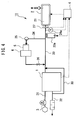
- FIG.4 is a system block diagram of the fuel cell system 11 including the hydrogen supply apparatus according to Embodiment 3.
- the fuel cell system 11 includes: the fuel cell 1; the high-pressure hydrogen tank 2; the air supply apparatus 3; the ECU 4; an odorant tank 5; a buffer tank 6; a heater 23a; a thermometer 24a; a hydrogen gas supply passage 30; an air supply passage 31; an anode off-gas passage 32; a circulating gas passage 33; and a hydrogen gas supply branch passage 34.
- the components already described above are identified by the same reference numerals, and thus the detailed description thereof will be omitted.
- the hydrogen gas supply passage 30 is connected, at its one end, to the high-pressure hydrogen tank 2, and is connected, at its other end, to the anode side of the fuel cell 1 to guide the hydrogen gas to the fuel cell 1.
- the hydrogen gas supply passage 30 is provided with a hydrogen flowmeter 27, the thermometer 24a, and the heater 23a in this order from the upstream side of the flow of the hydrogen gas.
- the hydrogen flowmeter 27 detects the flow rate of the hydrogen gas supplied from the high-pressure hydrogen tank 2.
- the hydrogen flowmeter 27 is electrically connected to the ECU 4, and the detected hydrogen flow rate is inputted to the ECU 4.
- the thermometer 24a detects the temperature of the hydrogen gas supplied from the high-pressure hydrogen tank 2.
- the thermometer 24a is electrically connected to the ECU 4, and the detected temperature is inputted to the ECU 4.
- the heater 23a is provided to the hydrogen supply passage 30, and heats the hydrogen gas, passing through the hydrogen supply passage 30, by the control of the ECU 4.
- the heater 23a can be placed, for example, at a lower part of the hydrogen supply passage 30, but is preferably placed so as to cover the hydrogen gas supply passage 30. This is because the hydrogen gas passing through the hydrogen gas supply passage 30 can be heated efficiently in such a configuration.
- the hydrogen gas supply branch passage 34 branches off from the hydrogen gas supply passage 30 at the downstream side of the heater 23a, and merges with the hydrogen gas supply passage 30 again. Further, the hydrogen gas supply branch passage 34 is provided with a pump 25, the odorant tank 5, the buffer tank 6, and an injector 26 in this order from the upstream side of the flow of the hydrogen gas.
- the pump 25 adjusts the flow rate of the hydrogen gas to which the odorant is to be added.
- the odorant tank 5 stores the odorant to be added to the hydrogen gas supplied from the high-pressure hydrogen tank 2.
- the buffer tank 6 temporarily retains the hydrogen gas supplied from the high-pressure hydrogen tank 2, adds the odorant, stored in the odorant tank 5, to the hydrogen gas, and carries out agitation.
- the injector 26 is supplied with the hydrogen gas, to which the odorant is added, from the high-pressure hydrogen tank 2, and mixes this hydrogen gas with the hydrogen gas guided through the hydrogen gas supply passage 30 functioning as a main passage.
- the air supply passage 31 is connected, at its one end, to the air supply apparatus 3, and is connected, at its other end, to the cathode side of the fuel cell 1 to guide air to the fuel cell 1.
- the anode off-gas passage 32 guides an anode off-gas, discharged from the anode side of the fuel cell 1, to the outside of the fuel cell system 11.
- the circulating gas passage 33 branches off from the anode off-gas passage, and merges with the hydrogen gas supply passage to guide the hydrogen gas, contained in the anode off-gas, to the fuel cell 1 again.
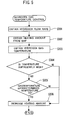
- FIG.5 is a flow chart illustrating the temperature control of the hydrogen gas according to Embodiment 3.
- the ECU 4 obtains the flow rate of the hydrogen gas supplied from the high-pressure hydrogen tank 2 to the fuel cell 1 (Step 301).
- the flow rate of the hydrogen gas can be obtained by the hydrogen flowmeter 27.
- the ECU 4 determines, from a map, a heater heating amount associated with the obtained hydrogen flow rate (Step 302).
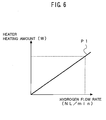
- a map of a necessary heating amount is shown in FIG. 6 .
- the horizontal axis represents the hydrogen flow rate (NL/min)
- the vertical axis represents the heater heating amount (W)
- the straight line P1 represents a variation in the heater heating amount.
- Such a map of the necessary heating amount may be stored in advance in a memory or the like of the ECU 4, for example.
- the ECU 4 obtains the temperature of the hydrogen gas supplied from the high-pressure hydrogen tank 2 (Step 303).
- the temperature of the hydrogen gas can be obtained by the thermometer 24a.
- the ECU 4 determines whether the temperature of the hydrogen gas obtained is sufficiently high (Step 304).
- the sufficiently high temperature of the hydrogen gas means a temperature at which the odorant to be added does not liquefy or solidify, and may be appropriately set depending on the odorant to be added. If the temperature of the hydrogen gas obtained is determined to be sufficiently high, the ECU 4 ends the temperature control process for the hydrogen gas according to Embodiment 3.
- the ECU 4 determines whether the temperature of the hydrogen gas obtained is equal to or lower than a predetermined temperature T3 (Step 305). If the temperature of the hydrogen gas is determined to be equal to or lower than the predetermined temperature T3, the ECU 4 increases the heating amount (Step 306), and ends the temperature control process for the hydrogen gas according to Embodiment 3.
- the predetermined temperature T3 may be the melting point or the boiling point of the odorant.
- the ECU 4 determines the heater heating amount from the map, and corrects the determined heater heating amount by the obtained temperature.
- the ECU 4 can obtain a more accurate heater heating amount.
- the odorant can be prevented from being liquefied or solidified.
- FIG.7 is a system block diagram of the fuel cell system 12 including the hydrogen supply apparatus according to Embodiment 4.
- the configuration of the fuel cell system 12 according to Embodiment 4 is basically similar to that of the fuel cell system 11 according to Embodiment 3 described above.
- the fuel cell system 12 according to Embodiment 4 is different from the fuel cell system 11 according to Embodiment 3 in that a heater 23b and a thermometer 24b are provided. It should be noted that the components already described above are identified by the same reference numerals, and thus the detailed description thereof will be omitted.
- the thermometer 24b detects the temperature of the odorant stored in the odorant tank 5. The detected temperature is inputted to the ECU 4.
- the heater 23b is provided at a lower part of the odorant tank 5, and heats the hydrogen gas, stored in the odorant tank 5, by the control of the ECU 4.
- the position at which the heater 23b is placed may be any position as long as the odorant stored in the odorant tank 5 can be heated, and is not limited to the lower part of the odorant tank 5.
- the odorant in a solid form or in a liquid form is accumulated at the lower part of the odorant tank 5, and therefore, the odorant can be efficiently heated by placing the heater 23b at the lower part of the odorant tank 5.
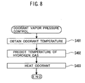
- FIG.8 is a flow chart illustrating the vapor pressure control of the odorant according to Embodiment 4.
- the ECU 4 obtains the temperature of the odorant, stored in the odorant tank 5, by the thermometer 24b (Step 401).
- the ECU 4 predicts how the temperature of the hydrogen gas, supplied from the high-pressure hydrogen tank 2, is reduced due to adiabatic expansion (Step 402).
- the temperature variation in the hydrogen gas due to adiabatic expansion is obtained as data beforehand, and based on this data, how the temperature of the hydrogen gas is reduced due to adiabatic expansion can be predicted. Further, the temperature of the hydrogen gas supplied from the high-pressure hydrogen tank 2 may be measured for a certain period of time, and based on this measurement, how the temperature is reduced thereafter may be predicted.
- the ECU 4 heats the odorant, stored in the odorant tank 5, by the heater 23b so that the odorant reaches a necessary vapor pressure (Step 403).
- the ECU 4 can determine the heater heating amount based on the temperature of the odorant obtained, the prediction of how the temperature of the hydrogen gas is reduced, and the property of the odorant.
- the heater heating amount is determined based on the temperature of the odorant, the temperature of the hydrogen gas, and the property of the odorant, the temperature of the odorant to be added to the hydrogen gas is raised in advance, and the odorant reaches a necessary vapor pressure, it is possible to prevent the liquefaction or solidification of the odorant, resulting from the cooling thereof by the hydrogen gas whose temperature has been reduced.
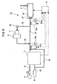
- FIG.9 is a schematic block diagram showing a fuel cell system 13 including a hydrogen supply apparatus according to Embodiment 5.
- the configuration of the fuel cell system 13 according to Embodiment 5 is basically similar to that of the fuel cell system 11 according to Embodiment 3.
- the fuel cell system 13 according to Embodiment 5 is different in configuration from the fuel cell system 11 according to Embodiment 3 in that a heater 23c and a thermometer 24c are further provided.
- the fuel cell system 13 according to Embodiment 3 includes the heater 23c, thus making it possible to heat the hydrogen gas, to which the odorant has been added through the buffer tank 6.
- the heating of the hydrogen gas, to which the odorant has been added may be carried out by obtaining the temperature of the hydrogen gas to which the odorant has been added, and by heating the hydrogen gas, to which the odorant has been added, to the extent that the odorant will not be liquefied or solidified, in addition to the execution of the control similar to the temperature control of the hydrogen gas according to Embodiment 3, for example.
- the fuel cell system 13 according to Embodiment 5 can heat the hydrogen gas again after the odorant has been added to the hydrogen gas, and can prevent the liquefaction or solidification of the odorant.
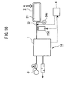
- FIG.10 is a schematic block diagram showing a fuel cell system 14 including a hydrogen supply apparatus according to Embodiment 6.
- the configuration of the fuel cell system 14 according to Embodiment 6 is basically similar to that of the fuel cell system 10 according to Embodiment 1.
- the fuel cell system 14 according to Embodiment 6 is different in configuration from the fuel cell system 10 according to Embodiment 1 in that a heater 23d and a thermometer 24d are provided instead of the heater 23 and the thermometer 24 in Embodiment 1, respectively.
- the fuel cell system 14 according to Embodiment 6 includes the heater 23d and the thermometer 24d, thus making it possible to heat the hydrogen gas mixed with the odorant and supplied from the high-pressure hydrogen tank 2. As a result, the odorant can be prevented from being liquefied or solidified.
- the temperature control of the hydrogen gas mixed with the odorant can be carried out by the ECU 4 based on the temperature of the hydrogen gas mixed with the odorant, detected by the thermometer 24d.
- FIG.11 is a flow chart illustrating the temperature control of the hydrogen gas according to Embodiment 6.
- the ECU 4 obtains the temperature of the hydrogen gas, mixed with the odorant, by the thermometer 24d (Step 501), and determines whether the obtained temperature of the hydrogen gas, mixed with the odorant, is equal to or lower than a predetermined temperature T4 (Step 502).
- the ECU 4 heats the hydrogen gas, mixed with the odorant, by the heater 23 (Step 503).
- the predetermined temperature T4 may be the melting point or the boiling point of the odorant.
- the hydrogen supply apparatus since the hydrogen supply apparatus according to the present invention is satisfactory so long as the temperature of the hydrogen gas to be supplied can be maintained at a temperature at which the hydrogen gas is easily mixed with the odorant, the present invention is not limited to the foregoing embodiments, and further includes a combination thereof as far as possible.
- each of the embodiments has been described using an example in which a hydrogen gas is used as a fuel gas.
- the present invention is not limited thereto, but examples of the fuel gas include a natural gas, and an LPG. Therefore, the present invention may be implemented as a fuel gas supply apparatus.
- the fuel gas supply apparatus is capable of suppressing a temperature reduction in fuel gas even at a low temperature, and is useful for the detection of the fuel gas leakage when an odorant and a fuel gas are mixed.
- the hydrogen supply apparatuses according to present invention described thus far include the following inventions.
- a hydrogen supply apparatus characterized by including: gas storage means for storing a hydrogen gas mixed with an odorant; gas supply means for supplying the hydrogen gas from the gas storage means; gas temperature detection means for detecting a temperature of the hydrogen gas stored in the gas storage means; and gas temperature reduction suppression means for suppressing a temperature reduction in hydrogen gas stored in the gas storage means, when the temperature of the hydrogen gas detected by the gas temperature detection means is equal to or lower than a predetermined temperature.
- a hydrogen supply apparatus characterized in that the predetermined temperature is equal to or higher than a melting point of the odorant.
- a hydrogen supply apparatus characterized in that the predetermined temperature is equal to or higher than a boiling point of the odorant.
- the hydrogen supply apparatus according to any one of Note 1 to Note 3, characterized by further including heating means for increasing the temperature of the hydrogen gas, in which the gas temperature reduction suppression means suppresses a temperature reduction in hydrogen gas by the heating means.
- the hydrogen supply apparatus according to any one of Note 1 to Note 3, characterized in that the gas temperature reduction suppression means decreases an amount of the hydrogen gas supplied by the gas supply means, to thereby suppress a temperature reduction in hydrogen gas.
Landscapes
- Chemical & Material Sciences (AREA)
- Engineering & Computer Science (AREA)
- General Chemical & Material Sciences (AREA)
- Sustainable Energy (AREA)
- Manufacturing & Machinery (AREA)
- Chemical Kinetics & Catalysis (AREA)
- Electrochemistry (AREA)
- Life Sciences & Earth Sciences (AREA)
- Sustainable Development (AREA)
- Organic Chemistry (AREA)
- Mechanical Engineering (AREA)
- Combustion & Propulsion (AREA)
- Inorganic Chemistry (AREA)
- General Engineering & Computer Science (AREA)
- Fuel Cell (AREA)
- Hydrogen, Water And Hydrids (AREA)
- Filling Or Discharging Of Gas Storage Vessels (AREA)
Abstract
Description
- The present invention relates to a hydrogen supply apparatus and a fuel gas supply apparatuses, each of which can be suitably used in a fuel cell system that generates electric energy by an electrochemical reaction in particular.
- A fuel cell system for obtaining electric energy by an electrochemical reaction between a hydrogen gas and an oxidation gas is known. The hydrogen gas serving as a fuel for this fuel cell system is flammable and odorless. On the other hand, in handling a hydrogen gas, it is preferable to be able to recognize the presence of the hydrogen gas with certainty.
- Therefore, a hydrogen supply apparatus that mixes a hydrogen gas with an odorant whose presence is recognizable due to its odor has been provided (see, for example, Patent Document 1). In this hydrogen supply apparatus, since the hydrogen gas and the odorant are mixed, the handling of the hydrogen gas is facilitated. Further, in the case where the leakage of the hydrogen gas has occurred, for example, the leakage of the hydrogen gas can be immediately detected due to the odor of the odorant.
[Patent document 1]JP 2002-29701 A
[Patent document 2]JP 2002-216812 A
[Patent document 3]JP 2004-111167 A - In order to detect the leakage of the hydrogen gas, the odorant and the hydrogen gas have to be mixed. However, in the case where the hydrogen gas has reached an extremely low temperature, the odorant has sometimes been solidified, and the hydrogen gas and the odorant have not been mixed at an extremely low temperature in some cases. In a system for storing the hydrogen gas in a high-pressure state, such as a high-pressure hydrogen tank in particular, the hydrogen gas has reached an extremely low temperature due to adiabatic expansion during the hydrogen supply, and the hydrogen gas has been supplied while not being mixed with the odorant in some cases.
- The present invention has been made in view of the various problems mentioned above, and it is an object of the present invention to provide a hydrogen supply apparatus capable of mixing an odorant with a hydrogen gas even at a low temperature, and detecting the hydrogen gas leakage.
- In order to solve the above-mentioned problems, the present invention adopts the following means. That is, a hydrogen supply apparatus according to the present invention includes: gas storage means for storing a hydrogen gas; odorant addition means for adding an odorant to the hydrogen gas; and temperature adjustment means for adjusting a temperature of at least one of the hydrogen gas, the odorant, and the hydrogen gas to which the odorant has been added.
- In the hydrogen supply apparatus, upon supply of the hydrogen gas stored in the gas storage means to the outside thereof, the pressure of the hydrogen gas is reduced, and the hydrogen gas undergoes adiabatic expansion. Thus, the temperature of the hydrogen gas is reduced. When the temperature of the hydrogen gas is reduced to a level equal to or lower than a predetermined temperature, the odorant to be mixed with the hydrogen gas is solidified or liquefied, and may have difficulty in mixing with the hydrogen gas.
- The hydrogen supply apparatus according to the present invention increases the temperature of at least one of the hydrogen gas and the odorant by the temperature adjustment means to suppress a temperature reduction in hydrogen gas, thus making it possible to maintain the odorant in a state in which (or at a temperature at which) the odorant can be mixed with the hydrogen gas. The hydrogen gas whose temperature is increased may be a hydrogen gas stored in the gas storage means, or may be a hydrogen gas supplied to the outside from the gas storage means. Further, the hydrogen gas supplied to the outside includes a hydrogen gas to which the odorant has been added. It should be noted that the hydrogen gas supply apparatus according to the present invention can add the odorant to the hydrogen gas by including odorant addition means. The hydrogen gas to which the odorant is to be added may be a hydrogen gas stored in the gas storage means, or may be a hydrogen gas discharged from the gas storage means. Further, the hydrogen gas, to which the odorant has been added by the odorant addition means, is supplied to the supply destination for the hydrogen gas, i.e., a hydrogen gas utilization apparatus such as a fuel cell or a hydrogen engine.
- Further, a hydrogen supply apparatus according to the present invention may be characterized by further including stored gas temperature detection means for detecting the temperature of the hydrogen gas stored in the gas storage means, and characterized in that the temperature adjustment means has gas temperature reduction suppression means for suppressing a temperature reduction in hydrogen gas stored in the gas storage means, when the temperature of the hydrogen gas detected by the stored gas temperature detection means is equal to or lower than a predetermined temperature.
- When the temperature of the hydrogen gas is equal to or lower than the predetermined temperature, a temperature reduction in hydrogen gas is suppressed by the gas temperature reduction suppression means, thus making it possible to maintain the odorant in a state in which (or at a temperature at which) the odorant can be mixed with the hydrogen gas. It should be noted that the hydrogen gas may be one mixed with the odorant. With the use of the hydrogen gas mixed with the odorant, the hydrogen gas mixed with the odorant can be supplied, and the detection accuracy of the hydrogen gas leakage can be improved. The predetermined temperature refers to a temperature below which the odorant is changed into, for example, a solid form incapable of mixing with the hydrogen gas, and is appropriately set in accordance with the properties of the odorant.
- Further, a hydrogen supply apparatus according to the present invention may be characterized by further including hydrogen gas temperature detection means for detecting the temperature of the hydrogen gas supplied from the gas storage means, and characterized in that the temperature adjustment means has heating means for increasing the temperature of the hydrogen gas supplied from the gas storage means, when the temperature of the hydrogen gas detected by the hydrogen gas temperature detection means is equal to or lower than a predetermined temperature.
- The above-mentioned stored gas temperature detection means detects the temperature of the hydrogen gas stored in the gas storage means; on the other hand, the hydrogen gas temperature detection means detects the temperature of the hydrogen gas, supplied to the outside of the gas storage means, at the outside of the gas storage means. That is, the hydrogen gas temperature detection means is capable of detecting the temperature of the hydrogen gas to be supplied to the outside of the gas storage means, which has been reduced due to adiabatic expansion. Based on the temperature of the hydrogen gas detected, the temperature adjustment means increases the temperature of the hydrogen gas supplied from the gas storage means, thereby making it possible to suppress the liquefaction or solidification of the odorant, resulting from the cooling thereof by the hydrogen whose temperature has been reduced. It should be noted that the heating means may be any means as long as it is capable of increasing the temperature of the hydrogen gas, and an example of which may be a heater.
- Further, the hydrogen supply apparatus according to the present invention may be characterized by further including an odorant temperature detection means for detecting the temperature of the odorant to be added by the odorant addition means, in which the temperature adjustment means has heating means for increasing the temperature of the odorant to be added by the odorant addition means, when the temperature of the odorant detected by the odorant temperature detection means is equal to or lower than a predetermined temperature.
- In order to increase the temperature of the odorant, it is preferable to calculate the vapor pressure of the odorant from the temperature of the odorant detected, and to apply heat to the odorant so that it reaches a necessary vapor pressure. The necessary vapor pressure refers to a pressure at which the odorant added to the hydrogen gas does not liquefy or solidify. The supply of heat to the odorant may be carried out by providing an odorant storage means for storing an odorant, for example, and by raising the temperature of the odorant storage means using heating means such as a heater. By adjusting the vapor pressure of the odorant in this manner, the liquefaction or solidification of the odorant can be suppressed. It should be noted that the heating means may be any means as long as it can increase the temperature of the odorant, and an example of which may be a heater.
- Further, the hydrogen supply apparatus according to the present invention may be characterized by further including: hydrogen gas temperature detection means for detecting the temperature of the hydrogen gas supplied from the gas storage means; and odorant temperature detection means for detecting the temperature of the odorant added by the odorant addition means, in which the temperature adjustment means has heating means for increasing the temperature of the odorant when at least one of the temperature of the hydrogen gas detected by the hydrogen gas temperature detection means and the temperature of the odorant detected by the odorant temperature detection means meets a predetermined condition.
- In the present invention, the temperature of the odorant is adjusted not only based on the temperature of the odorant detected by the odorant detection means, but also based on the temperature of the odorant detected by the hydrogen gas detection means. The predetermined condition means that the temperature of the hydrogen gas detected by the hydrogen gas temperature detection means is equal to or lower than a predetermined temperature, or the temperature of the odorant detected by the odorant temperature detection means is equal to or lower than a predetermined temperature. It should be noted that temperatures to be employed may be prioritized, and the temperature of the odorant may be increased based on a high-priority temperature. The heating means may be any means as long as it can increase the temperature(s) of the hydrogen gas and/or the odorant, and an example of which may be a heater.
- Further, a hydrogen supply apparatus according to the present invention may be characterized by further including hydrogen gas temperature detection means for detecting the temperature of the hydrogen gas supplied from the gas storage means, and characterized in that the temperature adjustment means has heating means for increasing the temperature of the hydrogen gas which is supplied from the gas storage means and to which the odorant has been added by the odorant addition means, when the temperature of the hydrogen gas detected by the hydrogen gas temperature detection means is equal to or lower than a predetermined temperature.
- According to the present invention, the temperature of the hydrogen gas, to which the odorant has been added by the odorant addition means, is adjusted, thereby suppressing the liquefaction or solidification of the odorant contained in the hydrogen gas. As described above, upon supply of the hydrogen gas stored in the gas storage means to the outside thereof, the temperature may be reduced due to adiabatic expansion. However, the causes of the temperature reduction in hydrogen gas are not limited to this, and it may also be possible that the temperature of the hydrogen gas is reduced, for example, by placing the hydrogen gas supply apparatus in a below-freezing environment. Even if the hydrogen gas or odorant is heated, the temperature reduction in hydrogen gas due to such a cause may occur because of the subsequent gradual loss of heat from the hydrogen gas, for example. According to the present invention, the temperature of the hydrogen gas after the addition of the odorant can be increased, and therefore, the liquefaction or the like of the odorant can be prevented even if the hydrogen gas supply apparatus is placed in a below-freezing environment.
- Further, a hydrogen supply apparatus according to the present invention may be characterized by further including hydrogen gas supply amount adjustment means for adjusting a supply amount of the hydrogen gas supplied from the gas storage means, and characterized in that the temperature adjustment means decreases the supply amount of the hydrogen gas, supplied from the gas storage means, by the hydrogen gas supply amount adjustment means, to thereby suppress a temperature reduction in hydrogen gas.
- Upon supply of the hydrogen gas from the gas storage means to the outside thereof, the hydrogen gas inside the gas storage means is decreased, and the temperature of the hydrogen gas is reduced due to adiabatic expansion. In particular, if the hydrogen gas is stored in a high-pressure state in a high-pressure hydrogen tank, for example, the pressure is sharply reduced, which results in a significant temperature reduction. However, upon decrease in the supply amount of the hydrogen gas, the temperature reduction is decreased.
- Accordingly, when the temperature of the hydrogen gas is equal to or lower than the predetermined temperature, the supply amount of the hydrogen gas is preferably decreased by the hydrogen gas supply amount adjustment means, and the temperature reduction can be suppressed to facilitate the mixing of the odorant with the hydrogen gas by decreasing the supply amount of the hydrogen gas.
- Further, a hydrogen supply apparatus according to the present invention may be characterized in that the predetermined temperature is equal to or higher than a melting point of the odorant. That is, when the temperature of the hydrogen gas detected by the stored gas temperature detection means or the hydrogen gas temperature detection means is equal to or lower than the predetermined temperature that is equal to or higher than the melting point of the odorant, the temperature adjustment means increases the temperature of at least one of the hydrogen stored in the gas storage means, the hydrogen gas supplied from the gas storage means, and the odorant.
- The melting point of the odorant is a temperature at which the odorant changes from a solid form to a liquid form. When the temperature of the odorant is reduced to be lower than the melting point thereof, the odorant is turned into a solid form, which has difficulty in mixing with the hydrogen gas. At such a temperature, the hydrogen gas and the odorant may not be mixed, and the detection accuracy of the hydrogen gas leakage may be degraded.
- Accordingly, the predetermined temperature is set equal to or higher than the melting point of the odorant so as to suppress a temperature reduction in hydrogen gas when the temperature of the hydrogen gas is equal to or lower than the predetermined temperature, thereby suppressing the solidification of the odorant, and allowing the odorant to be present in a liquid form or in a gaseous form. Generally, it is difficult to mix the odorant in a solid form with the hydrogen gas, and therefore, the odorant is provided in a liquid form or in a gaseous form, thus facilitating the mixing of the odorant with the hydrogen gas.
- It should be noted that the predetermined temperature is set equal to or higher than the melting point of the odorant because it is suitable for the odorant, which can be mixed with the hydrogen gas or is easily mixed therewith in a liquid state, and this temperature is appropriately changed in accordance with the properties of the odorant.
- Further, a hydrogen supply apparatus according to the present invention may be characterized in that the predetermined temperature is equal to or higher than a boiling point of the odorant. That is, when the temperature of the hydrogen gas, detected by the gas temperature detection means, is equal to or lower than the predetermined temperature that is equal to or higher than the boiling point of the odorant, the gas temperature reduction suppression means increases the temperature of at least one of the hydrogen stored in the gas storage means, the hydrogen gas supplied from the gas storage means, and the odorant.
- The boiling point of the odorant is a temperature at which the odorant changes from a liquid form to a gaseous form. When the temperature of the odorant is reduced to be lower than the boiling point thereof, the odorant is changed into a liquid form, which may have difficulty in mixing with the hydrogen gas depending on the properties of the odorant. The odorant, which will not be mixed with the hydrogen gas or have difficulty in mixing therewith in a liquid state, may degrade the detection accuracy of the hydrogen gas leakage.
- Accordingly, by suppressing a temperature reduction in hydrogen gas when the temperature of the hydrogen gas is at the predetermined temperature that is equal to or higher than the boiling point of the odorant, the odorant is kept in a gaseous state, thus making it possible to facilitate the mixing of the odorant with the hydrogen gas.
- It should be noted that the predetermined temperature is set equal to or higher than the boiling point of the odorant because it is suitable for the odorant, which can be mixed with the hydrogen gas or is easily mixed therewith in a gaseous state, and this temperature is appropriately changed in accordance with the properties of the odorant.
- Further, a hydrogen supply apparatus according to the present invention may be characterized by including: gas storage means for storing a hydrogen gas mixed with an odorant; gas supply means for supplying the hydrogen gas from the gas storage means; and gas temperature detection means for detecting the temperature of the hydrogen gas stored in the gas storage means; and gas temperature reduction suppression means for suppressing a temperature reduction in hydrogen gas stored in the gas storage means, when the temperature of the hydrogen gas detected by the gas temperature detection means is equal to or lower than a predetermined temperature.
- By suppressing a temperature reduction in hydrogen gas using the gas temperature reduction suppression means when the temperature of the hydrogen gas mixed with the odorant is equal to or lower than the predetermined temperature, the odorant can be maintained in a state in which (or at a temperature at which) it can be mixed with the hydrogen gas. Accordingly, the hydrogen gas mixed with the odorant can be supplied, thus enabling an improvement in the detection accuracy of the hydrogen gas leakage. The predetermined temperature is a temperature below which the odorant is changed into a solid state, for example, which cannot be mixed with the hydrogen gas, and is appropriately set in accordance with the properties of the odorant.
- Further, a hydrogen supply apparatus according to the present invention may be characterized by further including hydrogen gas temperature detection means for detecting the temperature of the hydrogen gas supplied from the gas storage means, and characterized in that the temperature adjustment means has heating means for increasing the temperature of the hydrogen gas which is supplied from the gas storage means and to which the odorant has been added by the odorant addition means, when the temperature of the hydrogen gas detected by the hydrogen gas temperature detection means is equal to or lower than a predetermined temperature. Thus, it is possible to increase the temperature of the hydrogen gas, which has been mixed with the odorant, and which is to be supplied to the outside from the gas storage means.
- Besides, the hydrogen supply apparatus according to the present invention may be characterized in that the gas temperature reduction suppression means suppresses a temperature reduction in hydrogen gas by decreasing the supply amount of the hydrogen gas.
- The hydrogen supply apparatus according to the present invention is satisfactory as long as it can suppress a temperature reduction in hydrogen gas when the temperature of the hydrogen gas is equal to or lower than a predetermined temperature at which the hydrogen gas has difficulty in mixing with the odorant; for example, in addition to the above-mentioned configurations, the apparatus may be provided with a limiter for stopping the supply of the hydrogen gas when the temperature thereof is equal to or lower than the predetermined temperature, so as to prevent a decrease in the hydrogen gas inside a hydrogen storage device, and to suppress a temperature reduction in hydrogen gas, or the apparatus may be provided with a plurality of gas storage means so as to use the hydrogen gas inside the gas storage means in which the temperature of the hydrogen gas is higher than the predetermined temperature, without the use of the gas storage means in which the temperature of the hydrogen gas is lower than the predetermined temperature, thereby maintaining the temperature of the hydrogen gas to be supplied above the predetermined temperature.
- Actually, each of the hydrogen supply apparatuses described above is an apparatus for supplying a hydrogen gas as a fuel gas. It should be noted that problems that the odorant is not solidified at a low temperature and the hydrogen gas is not mixed with the odorant at an extremely low temperature are not limited to the hydrogen gas, but those problems are possible in general fuel gas. Accordingly, an object of the present invention is to provide a fuel gas supply apparatus capable of mixing an odorant with a fuel gas even at a low temperature, and detecting the fuel gas leakage.
- In order to solve the above-mentioned problems, the present invention adopts the following means. That is, a fuel gas supply apparatus according to the present invention is characterized by including: gas storage means for storing a fuel gas; odorant addition means for adding an odorant to the fuel gas; and temperature adjustment means for adjusting the temperature of at least one of the hydrogen gas, the odorant, and the hydrogen gas to which the odorant has been added.
- The fuel gas supply apparatus according to the present invention has functions equivalent to those of each hydrogen supply apparatus already described above. This is because "fuel gas" is a generic name for a natural gas, a liquefied petroleum gas and the like, and a hydrogen gas is also included in a fuel gas. Accordingly, the configuration of the above-mentioned fuel gas supply apparatus can be described by replacing the hydrogen gas in each hydrogen supply apparatus already described above with a fuel gas. Therefore, the description thereof will be omitted.
- It should be noted that examples of the fuel gas include a natural gas, and a liquefied petroleum gas (LPG) composed of propane and butane and utilized as a mixture thereof. It should be noted that the natural gas includes a compressed natural gas (hereinafter, referred to as "CNG"). Further, if hydrogen is reformed by a reformer, a resultant reformed gas is also included in the fuel gas. Further, the fuel gas supply apparatus for supplying those fuel gases is applicable to a fuel cell serving as a fuel gas consumption device that consumes a fuel gas, a hydrogen engine, a CNG engine, an LPG engine, and a reformer for reforming a fuel gas, for example. It should be noted that a reformer for reforming a fuel gas refers to a reformer for reforming, for example, a fuel gas to hydrogen.
- According to the hydrogen supply apparatus of the present invention, a temperature reduction in a hydrogen gas can be suppressed even at a low temperature, an odorant and a hydrogen gas can be mixed, and the hydrogen gas leakage can be detected.
-
- [
FIG.1 ] A block diagram of afuel cell system 10 according toEmbodiment 1. - [
FIG.2 ] A flow chart illustrating the temperature control of a hydrogen gas in thefuel cell system 10 according toEmbodiment 1. - [
FIG.3 ] A flow chart illustrating the temperature control of a hydrogen gas in thefuel cell system 10 according toEmbodiment 2. - [
FIG.4 ] A block diagram of a waterfuel cell system 11 according toEmbodiment 3. - [
FIG.5 ] A flow chart illustrating the temperature control of a hydrogen gas according toEmbodiment 3. - [
FIG.6 ] A map of a necessary heating amount. - [
FIG.7 ] A block diagram of afuel cell system 12 according to Embodiment 4. - [
FIG.8 ] A flow chart illustrating the vapor pressure control of an odorant according to Embodiment 4. - [
FIG.9 ] A block diagram of afuel cell system 13 according toEmbodiment 5. - [
FIG.10 ] A block diagram of afuel cell system 14 according toEmbodiment 6. - [
FIG.11 ] A flow chart illustrating the temperature control of a hydrogen gas according toEmbodiment 6. - Embodiments of hydrogen supply apparatuses according to the present invention will be described in detail with reference to the drawings.
-
FIG. 1 is a system block diagram of afuel cell system 10 including a hydrogen supply apparatus according toEmbodiment 1. This fuel cell system includes: afuel cell 1; a high-pressure hydrogen tank 2 which stores a hydrogen gas serving as a fuel gas, and which functions as a hydrogen supply apparatus for supplying the hydrogen gas to thefuel cell 1; anair supply apparatus 3 for supplying air to thefuel cell 1; and an electronic control unit (ECU) 4 for controlling the various apparatuses. - The high-
pressure hydrogen tank 2 includes: atank 21 serving as gas storage means in which the hydrogen gas mixed with an odorant is stored; amain stop valve 22 through which the hydrogen gas is supplied to thefuel cell 1; aheater 23 serving as heating means for increasing the temperature of the hydrogen gas inside thetank 21; and athermometer 24 serving as gas temperature detection means for detecting the temperature of the hydrogen gas inside thetank 21. - The
fuel cell 1 causes an electrochemical reaction between the hydrogen gas and an oxidation gas via an electrolyte to obtain electric energy. Thefuel cell 1 according toEmbodiment 1 is a solid polymer electrolyte fuel cell frequently used in an electric automobile that runs using a fuel cell as a power supply. - The hydrogen gas stored in the high-
pressure hydrogen tank 2 contains methyl acrylate as an odorant. The odorant gives the hydrogen gas an odor by mixing the odorant into an odorless hydrogen gas, and serves to detect the hydrogen gas leakage. The methyl acrylate has a boiling point of about 80°C and a melting point of about -75°C. - The
main stop valve 22 serves as a supply port through which the hydrogen gas is supplied from thetank 21 to thefuel cell 1, and a supply flow rate therethrough is controlled by the ECU 4. Further, themain stop valve 22 is a solenoid valve, which is heated by passing an electric current therethrough, and which can indirectly heat the hydrogen gas to be supplied to thefuel cell 1. That is, themain stop valve 22 has a function of a heating means like theheater 23. - The
heater 23 is disposed at a lower part of thetank 21, and can directly heat the hydrogen gas inside thetank 21 with the control of the ECU 4. The position at which theheater 23 is placed may be any position as long as the hydrogen gas inside thetank 21 can be heated, and is not limited to the lower part of thetank 21; however, when the odorant is in a solid form or in a liquid form, the hydrogen gas is accumulated at the lower part of thetank 21, and therefore, the hydrogen gas can be efficiently heated by placing theheater 23 at the lower part of thetank 21. - The
thermometer 24 serves to detect the temperature of the hydrogen gas inside thetank 21, and is configured so that the temperature of the hydrogen gas detected is inputted to the ECU 4. The ECU 4 controls themain stop valve 22 or theheater 23 based on the temperature of the hydrogen gas detected by thethermometer 24, thereby maintaining the hydrogen gas inside thetank 21 at an appropriate temperature. - Hereinafter, the temperature control of the hydrogen gas in the
fuel cell system 10 configured as described above will be described in detail. Each of the various controls described below is executed by the ECU 4, and is a routine repeated at regular intervals. -
Embodiment 1 provides temperature control prior to the start of supply of the hydrogen gas, and is an embodiment in which when the temperature of the hydrogen gas inside the high-pressure hydrogen tank 2 is equal to or lower than a predetermined temperature, the temperature of the hydrogen gas is increased by theheater 23 or themain stop valve 22 to create a state where the mixing of the odorant with the hydrogen gas is facilitated, thus supplying the hydrogen gas mixed with the odorant to the fuel cell.FIG. 2 is a flow chart illustrating the temperature control of the hydrogen gas according toEmbodiment 1. - First, at the start of the supply of the hydrogen gas from the high-
pressure hydrogen tank 2 to thefuel cell 1, the temperature of the hydrogen gas inside thetank 21 is detected by the thermometer 24 (Step 101). The detected temperature is inputted to the ECU 4, and the ECU 4 determines whether the detected temperature is equal to or lower than a predetermined temperature T1 (Step 102). - In
Embodiment 1, methyl acrylate is used as the odorant, and the predetermined temperature T1 is set to -70°C, which is 5°C higher than -75°C, i.e., the melting point of methyl acrylate. That is, at a temperature higher than the predetermined temperature T1, the methyl acrylate is present as a liquid, and is in a state in which the methyl acrylate is easily mixed with the hydrogen gas. - When the temperature of the hydrogen gas detected is equal to or lower than the predetermined temperature T1, the ECU 4 carries out a heating process so as to prevent the odorant from being solidified (Step 103). In the heating process, the hydrogen gas may be directly heated by passing an electric current through the
heater 24, or the hydrogen gas to be supplied may be indirectly heated by passing an electric current through themain stop valve 22. After having carried out the heating process for a certain period of time by any one of methods, the temperature of the hydrogen gas inside thetank 21 is detected again by the thermometer 24 (Step 101). - It is determined again whether the temperature of the hydrogen gas detected is equal to or lower than T1 (Step 102), and the heating process is repeated until it is determined that the temperature of the hydrogen gas inside the
tank 21 is higher than the predetermined temperature T1. If the temperature of the hydrogen gas detected by thethermometer 24 is determined to be higher than the predetermined temperature T1 as a result of the determination ofStep 102, it is determined that the methyl acrylate serving as the odorant is in a liquid form and is mixed with the hydrogen gas, thus starting the supply of the hydrogen gas (Step 104). - It should be noted that if the supply of the hydrogen gas is continued, the temperature thereof is reduced due to the adiabatic expansion of the hydrogen gas, and therefore, the present control is repeated at certain periods of time even after the supply of the hydrogen gas has been started. As described above, according to
Embodiment 1, the hydrogen gas can be supplied at a temperature at which the odorant is easily mixed with the hydrogen gas, thus facilitating the mixing of the hydrogen gas with the odorant, and enabling an improvement in the detection accuracy of the hydrogen gas leakage. - Further, in
Embodiment 1, the temperature control of the hydrogen gas is performed before the start of supply of the hydrogen gas, but the temperature control does not necessarily have to be performed before the start of supply of the hydrogen gas, and may be performed during the supply of the hydrogen gas. It should be noted that when the temperature control is performed during the supply of the hydrogen gas, hydrogen supply stopping means for stopping the supply of the hydrogen gas may further be provided, if the temperature of the hydrogen gas is equal to or lower than the predetermined temperature T1. By providing the hydrogen supply stopping means, the supply of the hydrogen gas equal to or lower than the predetermined temperature is stopped, thus making it possible to prevent the hydrogen gas, which is not mixed with the odorant at a low temperature, from being supplied to thefuel cell 1. - In
Embodiment 2, when the temperature of the hydrogen gas inside the high-pressure hydrogen tank 2 is equal to or lower than the predetermined temperature, the flow rate of the hydrogen gas to be supplied to thefuel cell 1 is reduced, thereby preventing a decrease in the hydrogen gas inside thetank 21. By preventing the decrease in the hydrogen gas inside thetank 21, the temperature reduction in hydrogen gas due to adiabatic expansion is suppressed. The hydrogen gas temperature control according toEmbodiment 2 is the temperature control carried out during the supply of the hydrogen gas. It should be noted that the configuration of the fuel cell system is substantially the same as inEmbodiment 1; therefore, the same components are identified by the same reference numerals, and the description thereof will be omitted. - In the
fuel cell system 10 according toEmbodiment 2, the ECU 4, serving as gas temperature control means, has a function of adjusting the supply flow rate of the hydrogen gas to be supplied from the high-pressure hydrogen tank 2 to thefuel cell 1. If the temperature indicated by thethermometer 24 serving as gas temperature detection means is equal to or lower than a predetermined temperature, the ECU 4 reduces the supply flow rate of the hydrogen gas to suppress the adiabatic expansion of the hydrogen gas inside thetank 21, and to suppress the temperature reduction in hydrogen gas inside thetank 21. By suppressing the temperature reduction in hydrogen gas in this manner, the odorant contained in the hydrogen gas can be maintained at a temperature higher than a constant temperature at which the odorant is easily mixed with the hydrogen gas, and the hydrogen gas mixed with the odorant can be furnished to thefuel cell 1. -
FIG. 3 is a flow chart illustrating the temperature control of the hydrogen gas according toEmbodiment 2. First, the hydrogen gas is supplied from the high-pressure hydrogen tank 2 to thefuel cell 1 at a supply flow rate Q1 (Step 201). After a certain period of time has passed since the supply of the hydrogen gas, the temperature of the hydrogen gas inside thetank 21 is detected by the thermometer 24 (Step 202). The detected temperature is inputted to the ECU 4, and the ECU 4 determines whether the temperature of the hydrogen gas detected is equal to or lower than a predetermined temperature T2 (Step 203). - Also in
Embodiment 2, similarly toEmbodiment 1, methyl acrylate is used as the odorant. However, the predetermined temperature T2 is set to -65°C, which is 10°C higher than -75°C, i.e., the melting point of methyl acrylate. The reason the predetermined temperature T2 is set higher than the predetermined temperature inEmbodiment 1 is that inEmbodiment 1, the temperature reduction to the predetermined temperature T1 or lower is impossible since the hydrogen gas is heated by the heating means, but inEmbodiment 2, the slight temperature reduction to the predetermined temperature T2 or lower is possible since the temperature reduction is suppressed without performing any heating process. Accordingly, the predetermined temperature T2 inEmbodiment 2 is set 5°C higher than the predetermined temperature T1 inEmbodiment 1. - If the temperature of the hydrogen gas detected is equal to or lower than the predetermined temperature T2, the ECU 4 changes the supply flow rate of the hydrogen gas from Q1 to Q2 (where Q2 < Q1) in order to suppress the temperature reduction in hydrogen gas (Step 204). By reducing the supply flow rate of the hydrogen gas, the adiabatic expansion of the hydrogen gas inside the
tank 21 is suppressed, and the temperature reduction in hydrogen gas is suppressed. - After having supplied the hydrogen gas to the
fuel cell 1 at the supply flow rate Q2 for a certain period of time, the temperature of the hydrogen gas is detected again (Step 202). The ECU 4 determines whether the temperature of the hydrogen gas detected is equal to or lower than the predetermined temperature T2 (Step 203), and the hydrogen gas is supplied at the supply flow rate Q2 until the temperature of the hydrogen gas is determined to be higher than the predetermined temperature T2. If the temperature of the hydrogen gas detected by thethermometer 24 is determined to be higher than the predetermined temperature T2 as a result of the determination ofStep 203, the supply flow rate of the hydrogen gas is changed from Q2 to Q1, and the hydrogen gas is supplied at the supply flow rate Q1 (Step 205). - By detecting the temperature of the hydrogen gas during the supply of the hydrogen gas and reducing the supply flow rate of the hydrogen gas when the temperature of the hydrogen gas is reduced nearly to the melting point in this manner, the hydrogen gas can be supplied at a temperature at which the odorant is easily mixed with the hydrogen gas, thus making it possible to facilitate the mixing of the hydrogen gas with the odorant, and to improve the detection accuracy of the hydrogen gas leakage.
- Alternatively, in another embodiment, a fuel cell system including the plurality of high-
pressure hydrogen tanks 2 may be configured so that, instead of reducing the supply flow rate of the hydrogen gas when the temperature of the hydrogen gas is equal to or lower than the predetermined temperature T2, the high-pressure hydrogen tank, in which the temperature of the hydrogen gas is higher than the predetermined temperature T2, is selected to supply the hydrogen gas from the high-pressure hydrogen tank to the fuel cell. - Next, a
fuel cell system 11 including a hydrogen supply apparatus according toEmbodiment 3 will be described. In thefuel cell system 10 according toEmbodiment 1, the hydrogen gas inside thetank 21 is directly heated by the control of the ECU 4. On the other hand, in thefuel cell system 11 according toEmbodiment 3 heats the hydrogen gas, which has undergone adiabatic expansion and which is to be supplied from the high-pressure hydrogen tank 2. Upon supply of the hydrogen gas inside the high-pressure hydrogen tank 2 to the outside thereof, the hydrogen gas to be supplied may undergo adiabatic expansion due to pressure drop, and the temperature thereof may be reduced. Further, in a below-freezing environment, the temperature of the hydrogen gas is reduced. Upon reduction of the temperature of the hydrogen gas, there arises a problem that the odorant to be mixed therewith is liquefied or solidified. Thefuel cell system 11 according toEmbodiment 3 solves such a problem. -
FIG.4 is a system block diagram of thefuel cell system 11 including the hydrogen supply apparatus according toEmbodiment 3. Thefuel cell system 11 includes: thefuel cell 1; the high-pressure hydrogen tank 2; theair supply apparatus 3; the ECU 4; anodorant tank 5; abuffer tank 6; aheater 23a; athermometer 24a; a hydrogengas supply passage 30; anair supply passage 31; an anode off-gas passage 32; a circulatinggas passage 33; and a hydrogen gassupply branch passage 34. It should be noted that the components already described above are identified by the same reference numerals, and thus the detailed description thereof will be omitted. - The hydrogen
gas supply passage 30 is connected, at its one end, to the high-pressure hydrogen tank 2, and is connected, at its other end, to the anode side of thefuel cell 1 to guide the hydrogen gas to thefuel cell 1. The hydrogengas supply passage 30 is provided with ahydrogen flowmeter 27, thethermometer 24a, and theheater 23a in this order from the upstream side of the flow of the hydrogen gas. - The
hydrogen flowmeter 27 detects the flow rate of the hydrogen gas supplied from the high-pressure hydrogen tank 2. Thehydrogen flowmeter 27 is electrically connected to the ECU 4, and the detected hydrogen flow rate is inputted to the ECU 4. Further, thethermometer 24a detects the temperature of the hydrogen gas supplied from the high-pressure hydrogen tank 2. Thethermometer 24a is electrically connected to the ECU 4, and the detected temperature is inputted to the ECU 4. - The
heater 23a is provided to thehydrogen supply passage 30, and heats the hydrogen gas, passing through thehydrogen supply passage 30, by the control of the ECU 4. Theheater 23a can be placed, for example, at a lower part of thehydrogen supply passage 30, but is preferably placed so as to cover the hydrogengas supply passage 30. This is because the hydrogen gas passing through the hydrogengas supply passage 30 can be heated efficiently in such a configuration. - The hydrogen gas
supply branch passage 34 branches off from the hydrogengas supply passage 30 at the downstream side of theheater 23a, and merges with the hydrogengas supply passage 30 again. Further, the hydrogen gassupply branch passage 34 is provided with apump 25, theodorant tank 5, thebuffer tank 6, and aninjector 26 in this order from the upstream side of the flow of the hydrogen gas. - The
pump 25 adjusts the flow rate of the hydrogen gas to which the odorant is to be added. Theodorant tank 5 stores the odorant to be added to the hydrogen gas supplied from the high-pressure hydrogen tank 2. Thebuffer tank 6 temporarily retains the hydrogen gas supplied from the high-pressure hydrogen tank 2, adds the odorant, stored in theodorant tank 5, to the hydrogen gas, and carries out agitation. Further, theinjector 26 is supplied with the hydrogen gas, to which the odorant is added, from the high-pressure hydrogen tank 2, and mixes this hydrogen gas with the hydrogen gas guided through the hydrogengas supply passage 30 functioning as a main passage. - The
air supply passage 31 is connected, at its one end, to theair supply apparatus 3, and is connected, at its other end, to the cathode side of thefuel cell 1 to guide air to thefuel cell 1. The anode off-gas passage 32 guides an anode off-gas, discharged from the anode side of thefuel cell 1, to the outside of thefuel cell system 11. The circulatinggas passage 33 branches off from the anode off-gas passage, and merges with the hydrogen gas supply passage to guide the hydrogen gas, contained in the anode off-gas, to thefuel cell 1 again. - Hereinafter, the temperature control of the hydrogen gas in the
fuel cell system 11 configured as described above will be described in detail. Each of the various controls described below is executed by the above-mentioned ECU 4, and is a routine repeated at regular intervals. -
FIG.5 is a flow chart illustrating the temperature control of the hydrogen gas according toEmbodiment 3. First, the ECU 4 obtains the flow rate of the hydrogen gas supplied from the high-pressure hydrogen tank 2 to the fuel cell 1 (Step 301). The flow rate of the hydrogen gas can be obtained by thehydrogen flowmeter 27. - Next, the ECU 4 determines, from a map, a heater heating amount associated with the obtained hydrogen flow rate (Step 302). In this regard, a map of a necessary heating amount is shown in
FIG. 6 . As shown inFIG. 6 , the horizontal axis represents the hydrogen flow rate (NL/min), the vertical axis represents the heater heating amount (W), and the straight line P1 represents a variation in the heater heating amount. Such a map of the necessary heating amount may be stored in advance in a memory or the like of the ECU 4, for example. - Then, the ECU 4 obtains the temperature of the hydrogen gas supplied from the high-pressure hydrogen tank 2 (Step 303). The temperature of the hydrogen gas can be obtained by the
thermometer 24a. Subsequently, the ECU 4 determines whether the temperature of the hydrogen gas obtained is sufficiently high (Step 304). It should be noted that the sufficiently high temperature of the hydrogen gas means a temperature at which the odorant to be added does not liquefy or solidify, and may be appropriately set depending on the odorant to be added. If the temperature of the hydrogen gas obtained is determined to be sufficiently high, the ECU 4 ends the temperature control process for the hydrogen gas according toEmbodiment 3. - On the other hand, if the temperature of the hydrogen gas obtained is not determined to be sufficiently high, the ECU 4 determines whether the temperature of the hydrogen gas obtained is equal to or lower than a predetermined temperature T3 (Step 305). If the temperature of the hydrogen gas is determined to be equal to or lower than the predetermined temperature T3, the ECU 4 increases the heating amount (Step 306), and ends the temperature control process for the hydrogen gas according to
Embodiment 3. It should be noted that the predetermined temperature T3 may be the melting point or the boiling point of the odorant. - As described above, in the temperature control of the hydrogen gas according to
Embodiment 3, the ECU 4 determines the heater heating amount from the map, and corrects the determined heater heating amount by the obtained temperature. Thus, the ECU 4 can obtain a more accurate heater heating amount. As a result, in the case where the temperature of the hydrogen gas to be supplied is reduced due to adiabatic expansion or the like, the odorant can be prevented from being liquefied or solidified. - Next, a
fuel cell system 12 including a hydrogen supply apparatus according to Embodiment 4 will be described.FIG.7 is a system block diagram of thefuel cell system 12 including the hydrogen supply apparatus according to Embodiment 4. The configuration of thefuel cell system 12 according to Embodiment 4 is basically similar to that of thefuel cell system 11 according toEmbodiment 3 described above. Thefuel cell system 12 according to Embodiment 4 is different from thefuel cell system 11 according toEmbodiment 3 in that aheater 23b and athermometer 24b are provided. It should be noted that the components already described above are identified by the same reference numerals, and thus the detailed description thereof will be omitted. - The
thermometer 24b detects the temperature of the odorant stored in theodorant tank 5. The detected temperature is inputted to the ECU 4. Theheater 23b is provided at a lower part of theodorant tank 5, and heats the hydrogen gas, stored in theodorant tank 5, by the control of the ECU 4. The position at which theheater 23b is placed may be any position as long as the odorant stored in theodorant tank 5 can be heated, and is not limited to the lower part of theodorant tank 5. However, the odorant in a solid form or in a liquid form is accumulated at the lower part of theodorant tank 5, and therefore, the odorant can be efficiently heated by placing theheater 23b at the lower part of theodorant tank 5. - Next, the vapor pressure control of the odorant according to Embodiment 4 will be described.
FIG.8 is a flow chart illustrating the vapor pressure control of the odorant according to Embodiment 4. First, the ECU 4 obtains the temperature of the odorant, stored in theodorant tank 5, by thethermometer 24b (Step 401). - Then, the ECU 4 predicts how the temperature of the hydrogen gas, supplied from the high-
pressure hydrogen tank 2, is reduced due to adiabatic expansion (Step 402). The temperature variation in the hydrogen gas due to adiabatic expansion is obtained as data beforehand, and based on this data, how the temperature of the hydrogen gas is reduced due to adiabatic expansion can be predicted. Further, the temperature of the hydrogen gas supplied from the high-pressure hydrogen tank 2 may be measured for a certain period of time, and based on this measurement, how the temperature is reduced thereafter may be predicted. - Subsequently, the ECU 4 heats the odorant, stored in the
odorant tank 5, by theheater 23b so that the odorant reaches a necessary vapor pressure (Step 403). The ECU 4 can determine the heater heating amount based on the temperature of the odorant obtained, the prediction of how the temperature of the hydrogen gas is reduced, and the property of the odorant. - As described above, by carrying out the control so that the heater heating amount is determined based on the temperature of the odorant, the temperature of the hydrogen gas, and the property of the odorant, the temperature of the odorant to be added to the hydrogen gas is raised in advance, and the odorant reaches a necessary vapor pressure, it is possible to prevent the liquefaction or solidification of the odorant, resulting from the cooling thereof by the hydrogen gas whose temperature has been reduced.
- In addition to the above-described embodiments, for example, the hydrogen gas, to which the odorant has been added, may be heated.
FIG.9 is a schematic block diagram showing afuel cell system 13 including a hydrogen supply apparatus according toEmbodiment 5. The configuration of thefuel cell system 13 according toEmbodiment 5 is basically similar to that of thefuel cell system 11 according toEmbodiment 3. Thefuel cell system 13 according toEmbodiment 5 is different in configuration from thefuel cell system 11 according toEmbodiment 3 in that aheater 23c and athermometer 24c are further provided. Thefuel cell system 13 according toEmbodiment 3 includes theheater 23c, thus making it possible to heat the hydrogen gas, to which the odorant has been added through thebuffer tank 6. - It should be noted that the heating of the hydrogen gas, to which the odorant has been added, may be carried out by obtaining the temperature of the hydrogen gas to which the odorant has been added, and by heating the hydrogen gas, to which the odorant has been added, to the extent that the odorant will not be liquefied or solidified, in addition to the execution of the control similar to the temperature control of the hydrogen gas according to
Embodiment 3, for example. - Even if the hydrogen gas is heated by the
heater 23a, the temperature of the hydrogen gas is gradually reduced thereafter in a below-freezing environment or the like. However, thefuel cell system 13 according toEmbodiment 5 can heat the hydrogen gas again after the odorant has been added to the hydrogen gas, and can prevent the liquefaction or solidification of the odorant. - Further, in the case where the hydrogen gas mixed with the odorant is stored in the high-
pressure hydrogen tank 2, the hydrogen gas mixed with the odorant may be heated outside of the high-pressure hydrogen tank.FIG.10 is a schematic block diagram showing afuel cell system 14 including a hydrogen supply apparatus according toEmbodiment 6. The configuration of thefuel cell system 14 according toEmbodiment 6 is basically similar to that of thefuel cell system 10 according toEmbodiment 1. Thefuel cell system 14 according toEmbodiment 6 is different in configuration from thefuel cell system 10 according toEmbodiment 1 in that aheater 23d and athermometer 24d are provided instead of theheater 23 and thethermometer 24 inEmbodiment 1, respectively. Thefuel cell system 14 according toEmbodiment 6 includes theheater 23d and thethermometer 24d, thus making it possible to heat the hydrogen gas mixed with the odorant and supplied from the high-pressure hydrogen tank 2. As a result, the odorant can be prevented from being liquefied or solidified. - It should be noted that the temperature control of the hydrogen gas mixed with the odorant can be carried out by the ECU 4 based on the temperature of the hydrogen gas mixed with the odorant, detected by the
thermometer 24d.FIG.11 is a flow chart illustrating the temperature control of the hydrogen gas according toEmbodiment 6. The ECU 4 obtains the temperature of the hydrogen gas, mixed with the odorant, by thethermometer 24d (Step 501), and determines whether the obtained temperature of the hydrogen gas, mixed with the odorant, is equal to or lower than a predetermined temperature T4 (Step 502). Then, if the temperature of the hydrogen gas, mixed with the odorant, is determined to be equal to or lower than the predetermined temperature T4, the ECU 4 heats the hydrogen gas, mixed with the odorant, by the heater 23 (Step 503). On the other hand, if the temperature of the hydrogen gas mixed with the odorant is not determined to be equal to or lower than the predetermined temperature T4, the ECU 4 ends the temperature control of the hydrogen gas mixed with the odorant. It should be noted that the predetermined temperature T4 may be the melting point or the boiling point of the odorant. - In this manner, since the hydrogen supply apparatus according to the present invention is satisfactory so long as the temperature of the hydrogen gas to be supplied can be maintained at a temperature at which the hydrogen gas is easily mixed with the odorant, the present invention is not limited to the foregoing embodiments, and further includes a combination thereof as far as possible.
- It should be noted that each of the embodiments has been described using an example in which a hydrogen gas is used as a fuel gas. However, the present invention is not limited thereto, but examples of the fuel gas include a natural gas, and an LPG. Therefore, the present invention may be implemented as a fuel gas supply apparatus.
- The fuel gas supply apparatus according to the present invention is capable of suppressing a temperature reduction in fuel gas even at a low temperature, and is useful for the detection of the fuel gas leakage when an odorant and a fuel gas are mixed.
- The hydrogen supply apparatuses according to present invention described thus far include the following inventions.
- A hydrogen supply apparatus characterized by including: gas storage means for storing a hydrogen gas mixed with an odorant; gas supply means for supplying the hydrogen gas from the gas storage means; gas temperature detection means for detecting a temperature of the hydrogen gas stored in the gas storage means; and gas temperature reduction suppression means for suppressing a temperature reduction in hydrogen gas stored in the gas storage means, when the temperature of the hydrogen gas detected by the gas temperature detection means is equal to or lower than a predetermined temperature.
- A hydrogen supply apparatus according to
Note 1, characterized in that the predetermined temperature is equal to or higher than a melting point of the odorant. - A hydrogen supply apparatus according to
Note 1, characterized in that the predetermined temperature is equal to or higher than a boiling point of the odorant. - The hydrogen supply apparatus according to any one of
Note 1 to Note 3, characterized by further including heating means for increasing the temperature of the hydrogen gas, in which the gas temperature reduction suppression means suppresses a temperature reduction in hydrogen gas by the heating means. - The hydrogen supply apparatus according to any one of
Note 1 to Note 3, characterized in that the gas temperature reduction suppression means decreases an amount of the hydrogen gas supplied by the gas supply means, to thereby suppress a temperature reduction in hydrogen gas.
Claims (28)
- A hydrogen supply apparatus, comprising:gas storage means for storing a hydrogen gas;odorant addition means for adding an odorant to the hydrogen gas; andtemperature adjustment means for adjusting a temperature of at least one of the hydrogen gas, the odorant, and the hydrogen gas to which the odorant has been added.
- A hydrogen supply apparatus according to claim 1, further comprising stored gas temperature detection means for detecting the temperature of the hydrogen gas stored in the gas storage means,
wherein the temperature adjustment means has gas temperature reduction suppression means for suppressing a temperature reduction in hydrogen gas stored in the gas storage means, when the temperature of the hydrogen gas detected by the stored gas temperature detection means is equal to or lower than a predetermined temperature. - A hydrogen supply apparatus according to claim 1, further comprising hydrogen gas temperature detection means for detecting the temperature of the hydrogen gas supplied from the gas storage means,
wherein the temperature adjustment means has heating means for increasing the temperature of the hydrogen gas supplied from the gas storage means, when the temperature of the hydrogen gas detected by the hydrogen gas temperature detection means is equal to or lower than a predetermined temperature. - A hydrogen supply apparatus according to claim 1, further comprising odorant temperature detection means for detecting the temperature of the odorant to be added by the odorant addition means,
wherein the temperature adjustment means has heating means for increasing the temperature of the odorant to be added by the odorant addition means, when the temperature of the odorant detected by the odorant temperature detection means is equal to or lower than a predetermined temperature. - A hydrogen supply apparatus according to claim 1, further comprising hydrogen gas temperature detection means for detecting the temperature of the hydrogen gas supplied from the gas storage means; and
odorant temperature detection means for detecting the temperature of the odorant added by the odorant addition means,
wherein the temperature adjustment means has heating means for increasing the temperature of the odorant when at least one of the temperature of the hydrogen gas detected by the hydrogen gas temperature detection means and the temperature of the odorant detected by the odorant temperature detection means meets a predetermined condition. - A hydrogen supply apparatus according to claim 1, further comprising hydrogen gas temperature detection means for detecting the temperature of the hydrogen gas supplied from the gas storage means,
wherein the temperature adjustment means has heating means for increasing the temperature of the hydrogen gas which is supplied from the gas storage means and to which the odorant has been added by the odorant addition means, when the temperature of the hydrogen gas detected by the hydrogen gas temperature detection means is equal to or lower than a predetermined temperature. - A hydrogen supply apparatus according to any one of claims 1 to 6, further comprising hydrogen gas supply amount adjustment means for adjusting a supply amount of the hydrogen gas supplied from the gas storage means,
wherein the temperature adjustment means decreases the supply amount of the hydrogen gas, supplied from the gas storage means, by the hydrogen gas supply amount adjustment means, to thereby suppress a temperature reduction in hydrogen gas. - A hydrogen supply apparatus according to any one of claims 2 to 6, wherein the predetermined temperature is equal to or higher than a melting point of the odorant.
- A hydrogen supply apparatus according to any one of claims 2 to 6, wherein the predetermined temperature is equal to or higher than a boiling point of the odorant.
- A hydrogen supply apparatus, comprising:gas storage means for storing a hydrogen gas mixed with an odorant;gas supply means for supplying the hydrogen gas from the gas storage means;gas temperature detection means for detecting the temperature of the hydrogen gas stored in the gas storage means; andgas temperature reduction suppression means for suppressing a temperature reduction in hydrogen gas stored in the gas storage means, when the temperature of the hydrogen gas detected by the gas temperature detection means is equal to or lower than a predetermined temperature.
- A hydrogen supply apparatus according to claim 10, further comprising hydrogen gas temperature detection means for detecting the temperature of the hydrogen gas supplied from the gas storage means,
wherein the temperature adjustment means has heating means for increasing the temperature of the hydrogen gas supplied from the gas storage means, when the temperature of the hydrogen gas detected by the hydrogen gas temperature detection means is equal to or lower than a predetermined temperature. - A hydrogen supply apparatus according to claim 10 or 11, further comprising hydrogen gas supply amount adjustment means for adjusting a supply amount of the hydrogen gas supplied from the gas storage means,
wherein the temperature adjustment means decreases the supply amount of the hydrogen gas, supplied from the gas storage means, by the hydrogen gas supply amount adjustment means, to thereby suppress a temperature reduction in hydrogen gas. - A hydrogen supply apparatus according to claim 11 or 12, wherein the predetermined temperature is equal to or higher than a melting point of the odorant.
- A hydrogen supply apparatus according to claim 11 or 12, wherein the predetermined temperature is equal to or higher than a boiling point of the odorant.
- A fuel gas supply apparatus, comprising:gas storage means for storing a fuel gas;odorant addition means for adding an odorant to the fuel gas; andtemperature adjustment means for adjusting the temperature of at least one of the hydrogen gas, the odorant, and the hydrogen gas to which the odorant has been added.
- A fuel gas supply apparatus according to claim 15, further comprising stored gas temperature detection means for detecting the temperature of the fuel gas stored in the gas storage means,
wherein the temperature adjustment means has gas temperature reduction suppression means for suppressing a temperature reduction in fuel gas stored in the gas storage means, when the temperature of the fuel gas detected by the stored gas temperature detection means is equal to or lower than a predetermined temperature. - A fuel gas supply apparatus according to claim 15, further comprising fuel gas temperature detection means for detecting the temperature of the fuel gas supplied from the gas storage means,
wherein the temperature adjustment means has heating means for increasing the temperature of the fuel gas supplied from the gas storage means, when the temperature of the fuel gas detected by the fuel gas temperature detection means is equal to or lower than a predetermined temperature. - A fuel gas supply apparatus according to claim 15, further comprising odorant temperature detection means for detecting the temperature of the odorant to be added by the odorant addition means,
wherein the temperature adjustment means has heating means for increasing the temperature of the odorant to be added by the odorant addition means, when the temperature of the odorant detected by the odorant temperature detection means is equal to or lower than a predetermined temperature. - A fuel gas supply apparatus according to claim 15, further comprising fuel gas temperature detection means for detecting the temperature of the fuel gas supplied from the gas storage means; and
odorant temperature detection means for detecting the temperature of the odorant added by the odorant addition means,
wherein the temperature adjustment means has heating means for increasing the temperature of the odorant when at least one of the temperature of the hydrogen fuel gas detected by the fuel gas temperature detection means and the temperature of the odorant detected by the odorant temperature detection means meets a predetermined condition. - A fuel gas supply apparatus according to claim 15, further comprising fuel gas temperature detection means for detecting the temperature of the fuel gas supplied from the gas storage means,
wherein the temperature adjustment means has heating means for increasing the temperature of the fuel gas which is supplied from the gas storage means and to which the odorant has been added by the odorant addition means, when the temperature of the fuel gas detected by the fuel gas temperature detection means is equal to or lower than a predetermined temperature. - A fuel gas supply apparatus according to any one of claims 15 to 20, further comprising fuel gas supply amount adjustment means for adjusting a supply amount of the fuel gas supplied from the gas storage means,
wherein the temperature adjustment means decreases the supply amount of the fuel gas, supplied from the gas storage means, by the fuel gas supply amount adjustment means, to thereby suppress a temperature reduction in fuel gas. - A fuel gas supply apparatus according to any one of claims 16 to 20, wherein the predetermined temperature is equal to or higher than a melting point of the odorant.
- A fuel gas supply apparatus according to any one of claims 16 to 20, wherein the predetermined temperature is equal to or higher than a boiling point of the odorant.
- A fuel gas supply apparatus, comprising:gas storage means for storing a fuel gas mixed with an odorant;gas supply means for supplying the fuel gas from the gas storage means;gas temperature detection means for detecting the temperature of the fuel gas stored in the gas storage means; andgas temperature reduction suppression means for suppressing a temperature reduction in fuel gas stored in the gas storage means, when the temperature of the fuel gas detected by the gas temperature detection means is equal to or lower than a predetermined temperature.
- A fuel gas supply apparatus according to claim 24, further comprising fuel gas temperature detection means for detecting the temperature of the fuel gas supplied from the gas storage means,
wherein the temperature adjustment means has heating means for increasing the temperature of the fuel gas supplied from the gas storage means, when the temperature of the fuel gas detected by the fuel gas temperature detection means is equal to or lower than a predetermined temperature. - A fuel gas supply apparatus according to claim 24 or 25, further comprising fuel gas supply amount adjustment means for adjusting a supply amount of the fuel gas supplied from the gas storage means,
wherein the temperature adjustment means decreases the supply amount of the fuel gas, supplied from the gas storage means, by the fuel gas supply amount adjustment means, to thereby suppress a temperature reduction in hydrogen gas. - A fuel gas supply apparatus according to claim 24 or 25, wherein the predetermined temperature is equal to or higher than a melting point of the odorant.
- A fuel gas supply apparatus according to claim 24 or 25, wherein the predetermined temperature is equal to or higher than a boiling point of the odorant.
Applications Claiming Priority (3)
| Application Number | Priority Date | Filing Date | Title |
|---|---|---|---|
| JP2005259129 | 2005-09-07 | ||
| JP2006211730A JP5055883B2 (en) | 2005-09-07 | 2006-08-03 | Hydrogen supply device |
| PCT/JP2006/317670 WO2007029748A1 (en) | 2005-09-07 | 2006-09-06 | Hydrogen supply apparatus and fuel gas supply apparatus |
Publications (3)
| Publication Number | Publication Date |
|---|---|
| EP1935844A1 true EP1935844A1 (en) | 2008-06-25 |
| EP1935844A4 EP1935844A4 (en) | 2009-09-16 |
| EP1935844B1 EP1935844B1 (en) | 2015-05-13 |
Family
ID=37835865
Family Applications (1)
| Application Number | Title | Priority Date | Filing Date |
|---|---|---|---|
| EP06783199.0A Not-in-force EP1935844B1 (en) | 2005-09-07 | 2006-09-06 | Hydrogen supply apparatus and fuel gas supply apparatus |
Country Status (6)
| Country | Link |
|---|---|
| US (2) | US20090110990A1 (en) |
| EP (1) | EP1935844B1 (en) |
| JP (1) | JP5055883B2 (en) |
| CN (1) | CN101258103B (en) |
| CA (1) | CA2621401C (en) |
| WO (1) | WO2007029748A1 (en) |
Cited By (8)
| Publication number | Priority date | Publication date | Assignee | Title |
|---|---|---|---|---|
| WO2010022836A1 (en) * | 2008-08-27 | 2010-03-04 | Daimler Ag | Method and device for operating a gas tank in a vehicle |
| DE112007001822B4 (en) * | 2006-08-03 | 2012-07-26 | Toyota Jidosha K.K. | Hydrogen supply device and method for its control |
| EP2149596A4 (en) * | 2007-04-19 | 2013-01-02 | Toyota Motor Co Ltd | DEVICE FOR ADDING AN ODORANT SUBSTANCE AND SYSTEM FOR SUPPLYING GASEOUS FUEL |
| ITBO20110544A1 (en) * | 2011-09-23 | 2013-03-24 | Maria Cecilia Longhini | GASSOUS FUEL DISPENSER UNIT AND ADDITIVATING PRODUCTS OF A GAS SYSTEM FOR MOTOR VEHICLES. |
| EP2924788A3 (en) * | 2014-03-25 | 2015-10-21 | Aisin Seiki Kabushiki Kaisha | Fuel cell system |
| FR3032257A1 (en) * | 2015-02-04 | 2016-08-05 | Air Liquide | METHOD AND DEVICE FOR FILLING HYDROGEN RESERVOIR |
| EP3196533A1 (en) | 2016-01-25 | 2017-07-26 | Plastic Omnium Advanced Innovation and Research | Leakage detection system for pressure vessel |
| AT523678A1 (en) * | 2020-03-27 | 2021-10-15 | Avl List Gmbh | Dosing unit for generating a mixed gas |
Families Citing this family (19)
| Publication number | Priority date | Publication date | Assignee | Title |
|---|---|---|---|---|
| US20140255814A1 (en) | 2013-03-11 | 2014-09-11 | Ford Global Technologies, Llc | Fuel Cell Purge Line System |
| US9586806B2 (en) * | 2013-03-15 | 2017-03-07 | Honda Motor Co., Ltd. | Hydrogen fuel dispenser with pre-cooling circuit |
| US9464762B2 (en) * | 2013-03-15 | 2016-10-11 | Honda Motor Co., Ltd. | Hydrogen fuel dispenser with pre-cooling circuit |
| US9595725B2 (en) * | 2013-05-03 | 2017-03-14 | Ford Global Technologies, Llc | Heated ejector assembly for a fuel cell |
| JP5643887B2 (en) * | 2013-10-09 | 2014-12-17 | 本田技研工業株式会社 | Fuel cell system |
| JP5901608B2 (en) * | 2013-12-26 | 2016-04-13 | 本田技研工業株式会社 | Fuel filling system |
| DE102014019463A1 (en) * | 2014-12-23 | 2016-06-23 | Linde Aktiengesellschaft | Method and Odorierungsmittelspeicher for odorizing a Nutzgases, especially natural gas |
| JP6514611B2 (en) * | 2015-09-10 | 2019-05-15 | 本田技研工業株式会社 | Gas filling method |
| DK201600136A1 (en) * | 2016-03-02 | 2017-10-02 | Nel Hydrogen As | Cooling of a supply pipe in a hydrogen refueling system |
| FR3065375B1 (en) * | 2017-04-25 | 2019-06-28 | Arkema France | METHOD FOR ODORIZING CRYOGENIC FLUID |
| AU2019253959A1 (en) * | 2018-04-17 | 2020-12-03 | Electriq-Global Energy Solutions Ltd. | A hydrogen reactor with catalyst in flow conduit |
| CN109027663B (en) * | 2018-06-13 | 2021-01-15 | 浙江昊凡科技有限公司 | Standby filling device and filling system for hydrogen energy of hydrogen station |
| CN111174088B (en) * | 2019-01-16 | 2021-04-20 | 北方工业大学 | Temperature drop control system and method for deflation process of high-pressure gas cylinder |
| CN110567657A (en) * | 2019-08-16 | 2019-12-13 | 武汉格罗夫氢能汽车有限公司 | A method for monitoring hydrogen leakage of hydrogen energy locomotive |
| CN116877910A (en) * | 2019-09-19 | 2023-10-13 | 宝马股份公司 | Pressure vessel and motor vehicle |
| CN216903021U (en) * | 2021-12-09 | 2022-07-05 | 本田技研工业株式会社 | fuel cell system |
| US12290791B2 (en) * | 2022-05-03 | 2025-05-06 | GPL Odorizers LLC | Accurate odorization control |
| CN118031120A (en) * | 2024-03-27 | 2024-05-14 | 煤炭科学研究总院有限公司 | A method, system and vehicle for regulating temperature of vehicle hydrogen transmission pipeline |
| EP4667811A1 (en) * | 2024-06-20 | 2025-12-24 | Cummins, Inc. | Systems and methods for building pressure when using low pressure liquid hydrogen storage |
Family Cites Families (28)
| Publication number | Priority date | Publication date | Assignee | Title |
|---|---|---|---|---|
| US3123252A (en) * | 1964-03-03 | kuntz | ||
| US2322617A (en) * | 1941-09-24 | 1943-06-22 | Standard Oil Co California | Method and apparatus for odorizing liquefied gas |
| US3634053A (en) * | 1970-04-06 | 1972-01-11 | Inst Gas Technology | Odorization method and apparatus |
| US4025315A (en) * | 1971-05-19 | 1977-05-24 | San Diego Gas & Electric Co. | Method of odorizing liquid natural gas |
| US3907515A (en) * | 1972-10-02 | 1975-09-23 | San Diego Gas & Electric Co | Apparatus for odorizing liquid natural gas |
| US4219725A (en) * | 1978-08-01 | 1980-08-26 | The Dow Chemical Company | Heating apparatus for vaporizing liquefied gases |
| JPS59219392A (en) * | 1983-05-27 | 1984-12-10 | Tokyo Gas Eng Kk | Odorization of gas and device for it |
| US4611294A (en) * | 1984-05-01 | 1986-09-09 | Stanfill Ira C | Method of and apparatus for monitoring odorizer performance |
| US4684786A (en) * | 1984-08-01 | 1987-08-04 | Navistar International Corporation | Electrically heated fuel pick-up assembly for vehicle fuel tanks |
| US5105063A (en) * | 1990-12-17 | 1992-04-14 | Hockemier Roger G | Fuel heating system utilizing a liquid level responsive thermistor selector |
| JPH07507826A (en) * | 1992-06-16 | 1995-08-31 | アーゲーアー アクツイエボラーグ | Method and apparatus for adding odorant to consumer gas |
| US5531242A (en) * | 1993-12-28 | 1996-07-02 | American Air Liquide | Cylinder solvent pumping system |
| JPH08325583A (en) * | 1995-05-31 | 1996-12-10 | Mitsubishi Kakoki Kaisha Ltd | Line heater for city gas |
| JPH10279968A (en) * | 1997-03-31 | 1998-10-20 | Ootaki Gas Kk | Movable natural gas generator and natural gas supply method |
| US6142162A (en) * | 1999-06-18 | 2000-11-07 | Odoreyes Technology, Inc. | System and method for odorizing natural gas |
| US6609540B1 (en) * | 1999-06-24 | 2003-08-26 | Showa Denko Kabushiki Kaisha | Method and apparatus for supplying fluorine gas |
| JP2002029701A (en) * | 2000-07-10 | 2002-01-29 | Toyota Motor Corp | Hydrogen supply device, fuel cell device including the hydrogen supply device, and hydrogen detection method |
| JP4374782B2 (en) * | 2001-01-18 | 2009-12-02 | トヨタ自動車株式会社 | In-vehicle fuel cell system and control method thereof |
| TW499777B (en) * | 2001-04-16 | 2002-08-21 | Asia Pacific Fuel Cell Tech | Supply device for use with hydrogen source |
| JP2003028394A (en) * | 2001-07-13 | 2003-01-29 | Takata Corp | Heating apparatus for liquefied gas cylinder |
| JP4023731B2 (en) | 2002-09-18 | 2007-12-19 | 本田技研工業株式会社 | Hydrogen supply device |
| US6839508B2 (en) * | 2002-10-18 | 2005-01-04 | Csxt Intellectual Properties Corporation | Fuel heater |
| US20040197919A1 (en) * | 2003-04-01 | 2004-10-07 | Herman Gregory S. | Fuel cell leak detection |
| JP2004315566A (en) * | 2003-04-11 | 2004-11-11 | Ishikawajima Harima Heavy Ind Co Ltd | Gas odor method and device |
| EP1653148B1 (en) * | 2003-07-25 | 2018-05-02 | Toyota Jidosha Kabushiki Kaisha | Gas supply system |
| CA2445023C (en) * | 2003-11-06 | 2013-02-19 | Peter R. Toth | Heater control |
| US6898374B1 (en) * | 2003-11-10 | 2005-05-24 | Shiuan Shiau Wen | Fuel container having air supplying device |
| JP2007024192A (en) | 2005-07-15 | 2007-02-01 | Nissan Motor Co Ltd | Fuel supply device |
-
2006
- 2006-08-03 JP JP2006211730A patent/JP5055883B2/en not_active Expired - Fee Related
- 2006-09-06 EP EP06783199.0A patent/EP1935844B1/en not_active Not-in-force
- 2006-09-06 US US11/991,666 patent/US20090110990A1/en not_active Abandoned
- 2006-09-06 CA CA2621401A patent/CA2621401C/en not_active Expired - Fee Related
- 2006-09-06 WO PCT/JP2006/317670 patent/WO2007029748A1/en not_active Ceased
- 2006-09-06 CN CN200680032833XA patent/CN101258103B/en not_active Expired - Fee Related
-
2013
- 2013-03-08 US US13/790,457 patent/US8746274B2/en not_active Expired - Fee Related
Cited By (17)
| Publication number | Priority date | Publication date | Assignee | Title |
|---|---|---|---|---|
| DE112007001822B4 (en) * | 2006-08-03 | 2012-07-26 | Toyota Jidosha K.K. | Hydrogen supply device and method for its control |
| US8236073B2 (en) | 2006-08-03 | 2012-08-07 | Toyota Jidosha Kabushiki Kaisha | Hydrogen supplying apparatus and method for controlling hydrogen supplying apparatus |
| EP2149596A4 (en) * | 2007-04-19 | 2013-01-02 | Toyota Motor Co Ltd | DEVICE FOR ADDING AN ODORANT SUBSTANCE AND SYSTEM FOR SUPPLYING GASEOUS FUEL |
| WO2010022836A1 (en) * | 2008-08-27 | 2010-03-04 | Daimler Ag | Method and device for operating a gas tank in a vehicle |
| ITBO20110544A1 (en) * | 2011-09-23 | 2013-03-24 | Maria Cecilia Longhini | GASSOUS FUEL DISPENSER UNIT AND ADDITIVATING PRODUCTS OF A GAS SYSTEM FOR MOTOR VEHICLES. |
| EP2573448A1 (en) * | 2011-09-23 | 2013-03-27 | Maria Cecilia Longhini | Unit for delivering gaseous fuel and additive products in a motor vehicle gas system. |
| EP2924788A3 (en) * | 2014-03-25 | 2015-10-21 | Aisin Seiki Kabushiki Kaisha | Fuel cell system |
| WO2016124838A1 (en) * | 2015-02-04 | 2016-08-11 | L'air Liquide, Societe Anonyme Pour L'etude Et L'exploitation Des Procedes Georges Claude | Method and device for filling a hydrogen tank |
| FR3032257A1 (en) * | 2015-02-04 | 2016-08-05 | Air Liquide | METHOD AND DEVICE FOR FILLING HYDROGEN RESERVOIR |
| CN107208840A (en) * | 2015-02-04 | 2017-09-26 | 乔治洛德方法研究和开发液化空气有限公司 | Method and apparatus for filling a hydrogen tank |
| CN107208840B (en) * | 2015-02-04 | 2019-05-31 | 乔治洛德方法研究和开发液化空气有限公司 | Method and apparatus for filling a hydrogen tank |
| US10451219B2 (en) | 2015-02-04 | 2019-10-22 | L'air Liquide Societe Anonyme Pour L'etude Et L'exploitation Des Procedes Georges Claude | Method and device for filling a hydrogen tank |
| EP3196533A1 (en) | 2016-01-25 | 2017-07-26 | Plastic Omnium Advanced Innovation and Research | Leakage detection system for pressure vessel |
| WO2017129597A1 (en) * | 2016-01-25 | 2017-08-03 | Plastic Omnium Advanced Innovation And Research | Pressure vessel system. |
| US10823333B2 (en) | 2016-01-25 | 2020-11-03 | Plastic Omnium Advanced Innovation And Research | Pressure vessel system |
| AT523678A1 (en) * | 2020-03-27 | 2021-10-15 | Avl List Gmbh | Dosing unit for generating a mixed gas |
| AT523678B1 (en) * | 2020-03-27 | 2021-12-15 | Avl List Gmbh | Dosing unit for generating a mixed gas |
Also Published As
| Publication number | Publication date |
|---|---|
| CN101258103A (en) | 2008-09-03 |
| WO2007029748A1 (en) | 2007-03-15 |
| US20130189593A1 (en) | 2013-07-25 |
| EP1935844A4 (en) | 2009-09-16 |
| CA2621401A1 (en) | 2007-03-15 |
| JP5055883B2 (en) | 2012-10-24 |
| US8746274B2 (en) | 2014-06-10 |
| JP2007103347A (en) | 2007-04-19 |
| EP1935844B1 (en) | 2015-05-13 |
| US20090110990A1 (en) | 2009-04-30 |
| CN101258103B (en) | 2012-08-08 |
| CA2621401C (en) | 2013-04-02 |
Similar Documents
| Publication | Publication Date | Title |
|---|---|---|
| US8746274B2 (en) | Hydrogen supply apparatus and fuel gas supply apparatus | |
| EP2046466B1 (en) | In-vehicle hydrogen storage apparatus | |
| JP4622857B2 (en) | Gas supply device | |
| JP5178919B2 (en) | Power generation system | |
| JP2021173232A (en) | Engine system | |
| EP3182491B1 (en) | Solid oxide fuel cell system and method for controlling same | |
| US9252440B2 (en) | Gas supply system | |
| CN101488577B (en) | Gas supply system | |
| US8808935B2 (en) | Fuel cell system | |
| CN113471489B (en) | Control method, fuel cell system, vehicle, and readable storage medium | |
| JP2006331821A (en) | Fuel cell system | |
| US10763528B2 (en) | Operation of a fuel cell stack to prevent low oxygen concentrations in a surrounding enclosed space | |
| JPH01195671A (en) | Fuel cell power generation system and its operation method | |
| JP2007157492A (en) | Fuel cell system | |
| JP2012104434A (en) | Fuel cell system, and method for operating fuel cell system | |
| KR101300709B1 (en) | Auto operation system and method for forcing vaporizer of lng carrier | |
| WO2012063921A1 (en) | Fuel cell system and method for operating fuel cell system | |
| CN102834960A (en) | Fuel cell system, reformer system, and method of operating the fuel cell system | |
| JP2006029143A (en) | Fuel supply system for liquefied gas engine | |
| JP2010238456A (en) | Fuel cell system |
Legal Events
| Date | Code | Title | Description |
|---|---|---|---|
| PUAI | Public reference made under article 153(3) epc to a published international application that has entered the european phase |
Free format text: ORIGINAL CODE: 0009012 |
|
| 17P | Request for examination filed |
Effective date: 20080313 |
|
| AK | Designated contracting states |
Kind code of ref document: A1 Designated state(s): DE FR GB IT |
|
| DAX | Request for extension of the european patent (deleted) | ||
| RBV | Designated contracting states (corrected) |
Designated state(s): DE FR GB IT |
|
| A4 | Supplementary search report drawn up and despatched |
Effective date: 20090814 |
|
| 17Q | First examination report despatched |
Effective date: 20110318 |
|
| 17Q | First examination report despatched |
Effective date: 20110329 |
|
| RAP1 | Party data changed (applicant data changed or rights of an application transferred) |
Owner name: TOYOTA JIDOSHA KABUSHIKI KAISHA |
|
| RIC1 | Information provided on ipc code assigned before grant |
Ipc: C01B 3/00 20060101AFI20130809BHEP Ipc: H01M 8/04 20060101ALI20130809BHEP Ipc: F17C 7/00 20060101ALI20130809BHEP |
|
| RIN1 | Information on inventor provided before grant (corrected) |
Inventor name: MATSUBA, ATSUSHI Inventor name: IZUTANI, TAKAHIDE Inventor name: WATANABE, NOBUO Inventor name: FUJITANI, HIROSHI Inventor name: YOKOYAMA, TATSUAKI Inventor name: KUWAHARA, TAKUMI Inventor name: MATSUSUE, MASAAKI Inventor name: HIROSE, KATSUHIKO Inventor name: YUMITA, OSAMU Inventor name: OSHIKAWA, KATSUHIKO Inventor name: HIRAKATA, SYUUJI Inventor name: SUEMATSU, KEIGO |
|
| GRAP | Despatch of communication of intention to grant a patent |
Free format text: ORIGINAL CODE: EPIDOSNIGR1 |
|
| GRAJ | Information related to disapproval of communication of intention to grant by the applicant or resumption of examination proceedings by the epo deleted |
Free format text: ORIGINAL CODE: EPIDOSDIGR1 |
|
| GRAJ | Information related to disapproval of communication of intention to grant by the applicant or resumption of examination proceedings by the epo deleted |
Free format text: ORIGINAL CODE: EPIDOSDIGR1 |
|
| GRAP | Despatch of communication of intention to grant a patent |
Free format text: ORIGINAL CODE: EPIDOSNIGR1 |
|
| INTG | Intention to grant announced |
Effective date: 20141107 |
|
| GRAP | Despatch of communication of intention to grant a patent |
Free format text: ORIGINAL CODE: EPIDOSNIGR1 |
|
| INTC | Intention to grant announced (deleted) | ||
| INTG | Intention to grant announced |
Effective date: 20141211 |
|
| GRAS | Grant fee paid |
Free format text: ORIGINAL CODE: EPIDOSNIGR3 |
|
| GRAA | (expected) grant |
Free format text: ORIGINAL CODE: 0009210 |
|
| AK | Designated contracting states |
Kind code of ref document: B1 Designated state(s): DE FR GB IT |
|
| REG | Reference to a national code |
Ref country code: GB Ref legal event code: FG4D |
|
| REG | Reference to a national code |
Ref country code: DE Ref legal event code: R096 Ref document number: 602006045430 Country of ref document: DE Effective date: 20150625 |
|
| REG | Reference to a national code |
Ref country code: DE Ref legal event code: R084 Ref document number: 602006045430 Country of ref document: DE |
|
| REG | Reference to a national code |
Ref country code: DE Ref legal event code: R097 Ref document number: 602006045430 Country of ref document: DE |
|
| PLBE | No opposition filed within time limit |
Free format text: ORIGINAL CODE: 0009261 |
|
| STAA | Information on the status of an ep patent application or granted ep patent |
Free format text: STATUS: NO OPPOSITION FILED WITHIN TIME LIMIT |
|
| 26N | No opposition filed |
Effective date: 20160216 |
|
| PG25 | Lapsed in a contracting state [announced via postgrant information from national office to epo] |
Ref country code: IT Free format text: LAPSE BECAUSE OF FAILURE TO SUBMIT A TRANSLATION OF THE DESCRIPTION OR TO PAY THE FEE WITHIN THE PRESCRIBED TIME-LIMIT Effective date: 20150513 |
|
| GBPC | Gb: european patent ceased through non-payment of renewal fee |
Effective date: 20150906 |
|
| REG | Reference to a national code |
Ref country code: FR Ref legal event code: ST Effective date: 20160531 |
|
| PG25 | Lapsed in a contracting state [announced via postgrant information from national office to epo] |
Ref country code: GB Free format text: LAPSE BECAUSE OF NON-PAYMENT OF DUE FEES Effective date: 20150906 |
|
| PG25 | Lapsed in a contracting state [announced via postgrant information from national office to epo] |
Ref country code: FR Free format text: LAPSE BECAUSE OF NON-PAYMENT OF DUE FEES Effective date: 20150930 |
|
| PGFP | Annual fee paid to national office [announced via postgrant information from national office to epo] |
Ref country code: DE Payment date: 20180821 Year of fee payment: 13 |
|
| REG | Reference to a national code |
Ref country code: DE Ref legal event code: R119 Ref document number: 602006045430 Country of ref document: DE |
|
| PG25 | Lapsed in a contracting state [announced via postgrant information from national office to epo] |
Ref country code: DE Free format text: LAPSE BECAUSE OF NON-PAYMENT OF DUE FEES Effective date: 20200401 |