EP1935763B1 - Stanchion for a closeable loading aperture of a vehicle superstructure - Google Patents
Stanchion for a closeable loading aperture of a vehicle superstructure Download PDFInfo
- Publication number
- EP1935763B1 EP1935763B1 EP20070024735 EP07024735A EP1935763B1 EP 1935763 B1 EP1935763 B1 EP 1935763B1 EP 20070024735 EP20070024735 EP 20070024735 EP 07024735 A EP07024735 A EP 07024735A EP 1935763 B1 EP1935763 B1 EP 1935763B1
- Authority
- EP
- European Patent Office
- Prior art keywords
- stanchion
- protection element
- lever
- protective element
- stanchion according
- Prior art date
- Legal status (The legal status is an assumption and is not a legal conclusion. Google has not performed a legal analysis and makes no representation as to the accuracy of the status listed.)
- Active
Links
- 239000000463 material Substances 0.000 claims description 11
- 229920001971 elastomer Polymers 0.000 claims description 7
- 229910052751 metal Inorganic materials 0.000 claims description 5
- 239000002184 metal Substances 0.000 claims description 5
- 229910052782 aluminium Inorganic materials 0.000 claims description 3
- XAGFODPZIPBFFR-UHFFFAOYSA-N aluminium Chemical compound [Al] XAGFODPZIPBFFR-UHFFFAOYSA-N 0.000 claims description 3
- 239000004411 aluminium Substances 0.000 claims 1
- 230000001681 protective effect Effects 0.000 description 75
- XLYOFNOQVPJJNP-UHFFFAOYSA-N water Substances O XLYOFNOQVPJJNP-UHFFFAOYSA-N 0.000 description 6
- 230000007797 corrosion Effects 0.000 description 3
- 238000005260 corrosion Methods 0.000 description 3
- 230000001419 dependent effect Effects 0.000 description 3
- 150000003839 salts Chemical class 0.000 description 3
- 230000002349 favourable effect Effects 0.000 description 2
- AZDRQVAHHNSJOQ-UHFFFAOYSA-N alumane Chemical group [AlH3] AZDRQVAHHNSJOQ-UHFFFAOYSA-N 0.000 description 1
- 238000013459 approach Methods 0.000 description 1
- 238000005452 bending Methods 0.000 description 1
- 230000000903 blocking effect Effects 0.000 description 1
- 239000002131 composite material Substances 0.000 description 1
- 238000011109 contamination Methods 0.000 description 1
- 230000006735 deficit Effects 0.000 description 1
- 238000011161 development Methods 0.000 description 1
- 230000018109 developmental process Effects 0.000 description 1
- 238000006073 displacement reaction Methods 0.000 description 1
- 239000000806 elastomer Substances 0.000 description 1
- 230000005484 gravity Effects 0.000 description 1
- 230000007774 longterm Effects 0.000 description 1
- 239000004033 plastic Substances 0.000 description 1
- 229920003023 plastic Polymers 0.000 description 1
- 238000007789 sealing Methods 0.000 description 1
- 239000007921 spray Substances 0.000 description 1
Images


Classifications
-
- B—PERFORMING OPERATIONS; TRANSPORTING
- B62—LAND VEHICLES FOR TRAVELLING OTHERWISE THAN ON RAILS
- B62D—MOTOR VEHICLES; TRAILERS
- B62D33/00—Superstructures for load-carrying vehicles
- B62D33/02—Platforms; Open load compartments
- B62D33/0207—Connections of movable or detachable racks or stanchions to platforms
Definitions
- the invention relates to a stanchion for a loading opening of a vehicle body, which is provided in its lower part with a lever arrangement for locking the stanchion on a vehicle-fixed stake holder and with a protective element.
- stanchions As z. B. from the EP 0 941 195 B1 and the EP 1 517 824 B1 are known setting the stanchions on the closed by movable side walls or tarpaulins commercial vehicle body via vehicle-mounted stake holder, which are mounted in the lower part of the stanch around the level of the loading area of the vehicle.
- the locking of the stanchion on the stanchion holder is done by hand by stretching a provided on the stanchion of two articulated levers lever arms, of which usually a lever arm is provided with an actuating lever, which reduces the effort required to stretch the toggle lever assembly.
- the upper portion of the stanchion is in practice covered by the tarpaulin of the vehicle body, and is therefore not directly exposed to the influence of the weather or the salt water raised in winter driving.
- the lower part of the Runge is free and is therefore exposed to the influence of the weather and the prevailing especially during highway driving in the winter salt fog. In this way, it may come to the stanchion to unwanted contamination and corrosion, and thus in the long term to an impairment of the joint parts and locking elements of the stanchion.
- this is provided in its lower part with a lever arrangement for locking the stanchion on the vehicle-fixed stake holder.
- the lever of the lever arrangement is provided with a flat cover plate which conceals the mechanical elements arranged behind it as well as the stake holder. Between this cover plate and arranged on the left and right longitudinal profiles of Runge are column through which z. As dirt or water spray can pass through which the risk of corrosion or clogging or soiling of the parts arranged behind it.
- Such a protective element is suitable to cover the otherwise outwardly open Runge far enough that with locked Runge no dirt and no splash of water can reach the parts behind the Runge arranged behind. The risk of corrosion or clogging or soiling of the joints and moving parts arranged there is therefore at least reduced.
- the protective element automatically engages with the lever assembly closed to the longitudinal portion of the stanchion, whereas the protective element protrudes with the lever assembly open from the rearwardly arranged longitudinal portion of the stanchion, z. B. at an angle.
- the protective element has along its extension at least one deformation region over which changing distances can be compensated for when closing the lever arrangement.
- the protective element extends between the lower end of the stanchion and a lever of the lever arrangement.
- a lower edge of the protective element is attached to the stanchion, and an upper edge of the protective element is secured to a lever of the lever assembly, which is pivotally supported against the stanchion holder
- the protective element is a cover of a flat, generally flexible material. It is particularly advantageous if the protective element consists of a weatherproof rubber web.
- the width of the protective element is preferably greater than the sum of the width of the stanchion section covered by the protective element and the widths of the gaps arranged on either side of the stanchion to adjacent movable sidewalls. In this way, at the same time the protruding vertical edge portion of the protective element is bent inwardly with the creation of the usually hinged side walls, whereby in the columns on both sides of the stanchion a particularly advantageous seal to the respective side wall is reached.
- a further advantageous embodiment provides that the protective element is rigid and is secured in the region of its upper end to a lever of the lever arrangement.
- Rigid protective elements for example molded aluminum parts, are weather-resistant than, for example, rubber material existing protective elements and are characterized in this respect by a long service life.
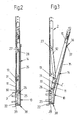
- Fig. 1 shows a truck with a box-shaped loading structure 1.
- two or more vertical stanchions 2. These are at the top of a rail 4 out, and lockable at the bottom of the loading floor 3 of the body 1. They can be moved after unlocking in the vehicle longitudinal direction, so as to increase the loading openings located between you in addition.
- the stanchions 2 Between the stanchions 2, the lower portions of the loading openings are closed by movable side walls 5.
- the side walls 5 are hinged down via corresponding hinges down. In the swung-up state, the side walls 5 can be locked to the stanchions, for which purpose additional locking elements can be attached laterally to the stanchions 2.
- FIGS. 2 and 3 show the lower longitudinal section of one of the stanchions in a sectional view.
- the stanchion is shown locked, whereas the Fig. 3 the Runge in partially unlocked state reproduces.
- At the upper end of each stanchion 2 is guided in the rail 4 of the vehicle body 1, so that it can be moved in the unlocked state in this rail 4 hanging in the vehicle longitudinal direction.
- a toggle lever assembly This is composed, inter alia, of a first lever arm 11 between the stanchion holder 10 and a toggle joint 13, and a second lever arm 12 between the toggle joint 13 and the stanchion 2.
- Another part of the locking of the stanchion serving lever assembly is a lever arm 11 via The lever 14 extends substantially in extension and for actuating the first lever arm 11 upwards, and it is coupled to the lever arm 11 with respect to the achievable pivotal movement.
- the lever 14 extends substantially in extension and for actuating the first lever arm 11 upwards, and it is coupled to the lever arm 11 with respect to the achievable pivotal movement.
- an additional manually releasable blocking element can be located on the handle 15 or in the region of the handle 15 in order to prevent accidental release and pivoting away of the actuating lever 14 to the outside.
- the elongated Runge 2 is preferably made of a metal profile or of several composite metal profiles.
- a positive locking element 22 is attached or formed on the stanchion 2. This sets, when the stanchion 2 is raised, from below against a corresponding form-fitting contour 23 of the vehicle-fixed stanchion holder 10, whereby the stanchion locked in this raised state form fit to the stanchion holder 10.
- the required lifting of the stanchion is carried out by the lever assembly 11, 12, 13, 14.
- Their first lever arm 11 is provided at the bottom with a bearing shell 25. About the bearing shell 25, the lever arm 11 is supported on a corresponding, part-cylindrical bearing contour of the stanchion holder 10 from.
- the bearing shell 25 forms together with the corresponding bearing contour a joint 26 between the first lever arm 11 and stanchion holder 10.
- This joint 26 is separable, ie the bearing shell 25 can be completely detached from the bearing contour of the stanchion holder 10, then the stanchion completely over Swing the stanchion holder 10 away outwards to be able to. This is necessary to then move the entire stanchion 2 in the vehicle longitudinal direction.
- the two lever arms 11, 12 are about the toggle joint 13 in articulated connection.
- the upper lever arm 12 is supported on the other hand at a hinge point 27 from. This is located on a mounted in the Runge 2 tab 28. Is in the in Fig. 3 shown starting position pushes the toggle lever assembly, ie by stretching the outwardly angled lever arms 11, 12, this leads to a displacement of Runge upwards, and thus to the already described locking of the very bottom of the stanchion arranged form-fitting element 22 on the form-fitting contour 23 of the stanchion holder 10.
- the required for the extension of the toggle lever assembly force is applied by the provided with the handle 15 lever 14. This is connected via a pivot axis 30 with the lever arm 11 arranged behind it.
- serving as an actuating lever 14 is not rigidly to the lever arm 11, but about the pivot axis 30 slightly pivotable to the lever arm 11.
- the pivot axis 30 is located relatively far below the first lever arm eleventh in the vicinity of the bearing shell 25.
- the possible pivoting path S is limited by a Schwenkwegbegrenzer 31 to 1 ° to 10 °.
- the lower longitudinal section of the stanchion is covered to the outside by a protective element 35.
- the protective element 35 further prevents rainwater or even splash water from reaching the vehicle interior in the region of the stanchion, where it can lead to moisture damage to the cargo.
- the protective element 35 according to the embodiments in the FIGS. 11 to 18 over its entire length of a rigid material.
- the upper edge 36 of the in FIGS. 2 to 5 shown protective element 35 is attached by means of an attached bar 37 on the outside of the lever 14, preferably just below the handle 15. In the region of its lower edge 38, the protective element 35 is guided around the lower end of the stanchion 2, and at the downwardly facing end face 39 attached. Also for attachment of this lower edge 38 on the front side 39 may be useful from the outside patch bar comparable to the bar 37.
- the attachment of both the upper and the lower edge is otherwise by riveting, wherein the rivet 34 and the respective, patch bar 37 passes.
- the cover 35 is a generally flat and band-shaped strip of rubber or a similar flexible or bendable material.
- the cover 35 with unlocked Runge ( Fig. 4 ) bend or curve over its entire length, and thus adapt well to the pivoting of the operating lever 14.
- the cover 35 is stretched and covers the outside of the stanchion 2 flat and completely. Splashing water and dirt can not reach the area of the sensitive joints of the lever arrangement arranged behind.
- FIG. 6 Another embodiment for the cover of the stanchion is in Fig. 6 shown. Also shown here is the adjacent side wall 5, which can be locked laterally next to the stanchion 2.
- the protective element 35 serving as a cover is formed by a strip of rubber which can be deformed over its entire length.
- the width BS of the protection member 35 exceeds the width BR of the ridge portion covered by the protection member 35.
- the width BS of the protective member is larger than the sum of the width BR of the stile portion covered by the protective member and the widths of the gaps 40 disposed on both sides of the stanchion 2.
- the gaps 40 are adjacent ones Side walls 5.
- the deformable protective element 35 cover the stanchion 2 arranged behind it, but in addition it also seals against the side wall 5. Splashing water and dirt can therefore no longer easily pass between the stanchion 2 and the adjacent side wall 5. Further, the inwardly bent edge portions 46a, 46b prevent the airstream from reaching under the protection member 35 from the side and lifting it off the stanchion or fluttering in the airstream.
- the protective element 35 also has the already described excess width in order to provide an additional seal when the side wall 5 is folded.
- the protective element 35 is pulled in the region of its lower edge 38 around the lower stake end, and provided for attachment to an angle piece or here a cap 45. This is on the downwardly facing end face 39 of the stanchion (see. Fig. 5 riveted. Since the cap 45 also has lateral surfaces 48, it causes in this area a concern of the edge portions 46a, 46b of the protective element 35 on the respective sides of the stanchion 2. However, this applies only to this lower portion of the protective element 35, whereas the elastic Edge sections 46a, 46b can issue freely upwards, and they are created there only by closing the side walls 5.
- the upper edge 36 of the cover is fastened by means of the strip 37 already described, e.g. with the rivet 34.
- the strip 37 should be shorter in width than the entire width BS of the underlying protective element 35, but not longer than the width BR of the covered Rurgiabitess. In this way, prevents the bar 37 that bulges inwardly bent edge portions 46a, 46b due to the bending forces of the upper edge 36 of the protective element 35, and here dirt or rainwater can penetrate from above.
- the attachment of the flexible protective element 35 is carried out both with its lower edge 38, as with its upper edge 36a on the Runge 2 itself.
- the lower edge 38 is permanently attached to the sides of the stanchion, as by two by the folded edge portions 46a, 46b
- the upper edge 36a of the cover can be suspended by hand in the stanchion 2.
- the Runge 2 can be mounted at the upper edge 36a as a fastening hook 50th attached serving profile, which can be on a crosspiece 51, here a cross pin.
- the protective element 35 sets when closing the lever assembly 11, 12, 14 is not automatically at the longitudinal portion of the stanchion 2. It is necessary after closing the lever assembly 11, 12, 14 to mount the protective element 35 by hand on the crosspiece 51 of the stanchion, whereby the contact of the protective element 35 is achieved at the longitudinal portion of the stanchion 2. Since the protective element 35 according to the FIGS. 9 and 10 so that is not dependent on the geometry of the lever 11, 12, 14 used, it is particularly suitable as a retrofit solution for stanchions without protective element.
- the upper edge 36a of the protective element 35 Before opening or unlocking the stanchion 2, therefore, the upper edge 36a of the protective element 35 must first be unhooked.
- the protective element 35 including its edge portions 46a, 46b arching outwardly along the greatest part of its length, then hangs limply down, as in FIG Fig. 10 shown. In this way, the locking elements 52 of the stanchion 2 arranged behind are free. The restoration of the cover is done in reverse order.
- a preferred material for in the FIGS. 2 to 10 shown cover 35 is mechanically resistant, weatherproof and largely UV-resistant rubber.
- other materials can be used as far as they have these properties and they are deformable along their extension and including their mutual edge portions in at least one deformation region.
- the protective element 35 consists of a rigid material, preferably aluminum. However, other metallic and also rigid elastomer materials and plastics are also conceivable.
- the rigid protective element 35 is pivotally mounted in the region of its upper end 60 to the lever 14 of the lever assembly.
- the upper end 60 of the protective element 35 is provided for this purpose with at right angles angled tabs 62, which are inserted into slot-shaped openings 64 of the lever 14 of the vehicle outside.
- the tabs 62 are shorter than the slots 64 so that the tabs 62 can reciprocate within the slots 64.
- the protective element 35 has a between the Tabs 62 extending securing bolt 63, which is located on the vehicle inner side of the lever 14, see. Fig. 17 , In this way, the protective element 35 or its upper end 60 is hinged relative to the lever 14, but at the same time in the longitudinal direction of the lever 14 movable.
- the upper end 60 of the protective element 35 and the tabs 62 also sits pivotally in the openings 64.
- the gravity-dependent depending protection element 35 regardless of the pivot angle of the lever 14 maintains an approximately vertical position.
- the pivot angle between the upper end 60 and the lever 14 is reduced, whereby the protective element 35 of the stanchion 2 approaches, until finally, as shown in FIG Fig. 11 attached to this.
- this is laterally provided there with angular entrainment elements 65.
- the tab-shaped driving elements 65 are taken or pushed inwards, so that the protective element 35 abuts against the stanchion 2 from the outside, and is locked in this position by the side wall.
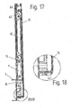
- the in the FIGS. 14 to 18 shown Runge 2 differs from the Runge 2 as shown in the FIGS. 11 to 13 due to the lower end 61 of the protective element 35.
- the attachment of the upper end 60 of the protective element 35 is analogous to the previously described embodiment. While in the execution after Fig. 11 to 13 a length compensation, as in the previously using the FIGS. 2 to 10 described embodiments is achieved by the deformation region, due to the Wegschwenkens the lower end 61 of the protective element 35 is not required, the lower end 61 remains in the execution FIGS. 14 to 18 also locked when opening the lever assembly in the lower part of the stanchion 2.
- a pivotable connector 66 is provided in the region of the lower end 61 of the protective element 35. This consists of a provided in the stanchion 2 opening 68 and an inserted into this male element 67.
- the male element 67 is, as in particular the illustrations in FIGS. 17 and 18 can recognize, formed by a double bend at the lower end of the protective element 35.
- the material thickness of the male member 67 is selected so that a certain play in the opening 68 remains forwards and backwards, so that the male member 67 with the opening 68 a pivotable connector forms, see. FIGS. 14 . 16 ,
- the width B 1 of the opening 68 is selected to be greater than the width B 2 of the plug element 67.
- the protective element 35 when closing the lever assembly and the associated lifting the stanchion 2 are pressed from below against the stanchion holder 10. As a result, rattling noise of the protective element 35 are suppressed while driving.
- the protective element 35 is in the provided at the lower end 61 of the protective element 35 male member 67 to an integral bend of the protective element 35.
- the protective element 35 is with the exception of the bolt 63 as a sheet-metal forming part, for example, made of aluminum, in one piece.
Description
Die Erfindung betrifft eine Runge für eine Ladeöffnung eines Fahrzeugaufbaus, welche in ihrem unteren Teil mit einer Hebelanordnung zum Verriegeln der Runge an einem fahrzeugfesten Rungenhalter und mit einem Schutzelement versehen ist.The invention relates to a stanchion for a loading opening of a vehicle body, which is provided in its lower part with a lever arrangement for locking the stanchion on a vehicle-fixed stake holder and with a protective element.
Bei Rungen, wie sie z. B. aus der
Der obere Bereich der Runge wird in der Praxis durch die Plane des Fahrzeugaufbaus bedeckt, und ist daher nicht unmittelbar dem Einfluss der Witterung oder des im Winterfahrbetrieb aufgewirbelten Salzwassers ausgesetzt. Hingegen liegt der untere Teil der Runge frei und ist daher dem Einfluss der Witterung sowie dem gerade bei Autobahnfahrten im Winter vorherrschenden Salznebel ausgesetzt. Auf diese Weise kann es an der Runge zu unerwünschten Verschmutzungen und auch Korrosionen kommen, und damit langfristig zu einer Beeinträchtigung der Gelenkteile und Verriegelungselemente der Runge.The upper portion of the stanchion is in practice covered by the tarpaulin of the vehicle body, and is therefore not directly exposed to the influence of the weather or the salt water raised in winter driving. By contrast, the lower part of the Runge is free and is therefore exposed to the influence of the weather and the prevailing especially during highway driving in the winter salt fog. In this way, it may come to the stanchion to unwanted contamination and corrosion, and thus in the long term to an impairment of the joint parts and locking elements of the stanchion.
Bei der Runge nach der
Es ist daher das Ziel der Erfindung, durch geeignete konstruktive Maßnahmen derartige Gefahren einer Schädigung der Runge zumindest gering zu halten.It is therefore the object of the invention to keep such risks of damage to the stanchion at least low by suitable design measures.
ZurLösung wird eine Runge mit den Merkmalen des Patentanspruchs 1 vorgeschlagen.To solve a stanchion with the features of
Ein solches Schutzelement ist geeignet, die ansonsten nach außen offene liegende Runge soweit abzudecken, dass bei verriegelter Runge kein Schmutz und kein Spritzwasser an die dahinter angeordneten Teile der Runge gelangen kann. Die Gefahr von Korrosionen oder des Zusetzens oder Verschmutzens der dort angeordneten Gelenke und beweglichen Teile wird daher zumindest reduziert.Such a protective element is suitable to cover the otherwise outwardly open Runge far enough that with locked Runge no dirt and no splash of water can reach the parts behind the Runge arranged behind. The risk of corrosion or clogging or soiling of the joints and moving parts arranged there is therefore at least reduced.
Gemäß einer Ausführungsform wird vorgeschlagen, dass sich das Schutzelement bei geschlossener Hebelanordnung selbsttätig an den Längsabschnitt der Runge legt, wohingegen das Schutzelement bei geöffneter Hebelanordnung von dem dahinter eingeordneten Längsabschnitt der Runge absteht, z. B. in einem Winkel. Durch das gleichsame Anlegen des Schutzelements erst beim Schließen der Hebelanordnung sind keine separaten Handgriffe für die Anbringung des Schutzelements nötig. Es ergibt sich ein guter Bedienkomfort der Runge.According to one embodiment, it is proposed that the protective element automatically engages with the lever assembly closed to the longitudinal portion of the stanchion, whereas the protective element protrudes with the lever assembly open from the rearwardly arranged longitudinal portion of the stanchion, z. B. at an angle. By the same application of the protective element only when closing the lever assembly no separate handles for attaching the protective element are needed. This results in a good ease of use of Runge.
Gemäß einer Ausführungsform weist das Schutzelement entlang seiner Erstreckung mindestens einen Verformungsbereich auf, über den beim Schließen der Hebelanordnung sich verändernde Abstände ausgeglichen werden können.According to one embodiment, the protective element has along its extension at least one deformation region over which changing distances can be compensated for when closing the lever arrangement.
Gemäß einer Ausführungsform erstreckt sich das Schutzelement zwischen dem unteren Ende der Runge und einem Hebel der Hebelanordnung. Vorzugsweise ist ein unterer Rand des Schutzelementes an der Runge, und ein oberer Rand des Schutzelements an einem Hebel der Hebelanordnung befestigt, der schwenkbeweglich gegen den Rungenhalter abgestützt istAccording to one embodiment, the protective element extends between the lower end of the stanchion and a lever of the lever arrangement. Preferably, a lower edge of the protective element is attached to the stanchion, and an upper edge of the protective element is secured to a lever of the lever assembly, which is pivotally supported against the stanchion holder
Gemäß einer bevorzugten Ausführungsform ist das Schutzelement eine Abdeckung aus einem flachen, insgesamt biegsamen Material. Von besonderem Vorteil ist, wenn das Schutzelement aus einer wetterfesten Bahn aus Gummi besteht.According to a preferred embodiment, the protective element is a cover of a flat, generally flexible material. It is particularly advantageous if the protective element consists of a weatherproof rubber web.
Vorzugsweise ist die Breite des Schutzelementes größer, als die Summe aus der Breite des durch das Schutzelement abgedeckten Rungenabschnittes und den Breiten der beiderseits der Runge angeordneten Spalte zu angrenzenden, beweglichen Bordwänden. Auf diese Weise wird mit dem Anlegen der üblicherweise abklappbaren Bordwände zugleich der überstehende vertikale Randabschnitt des Schutzelements nach innen gebogen, wodurch in den Spalten beiderseits der Runge eine besonders vorteilhafte Abdichtung zu der jeweiligen Bordwand hin erreicht wird.The width of the protective element is preferably greater than the sum of the width of the stanchion section covered by the protective element and the widths of the gaps arranged on either side of the stanchion to adjacent movable sidewalls. In this way, at the same time the protruding vertical edge portion of the protective element is bent inwardly with the creation of the usually hinged side walls, whereby in the columns on both sides of the stanchion a particularly advantageous seal to the respective side wall is reached.
Zur Erzielung einer günstigen Verformung des Schutzelementes beim Anklappen der Bordwände, ohne dass es zu dem Entstehen von Spalten kommt, wird mit einer weiteren Ausgestaltung vorgeschlagen, dass auf den oberen Rand des Schutzelementes von außen eine Leiste aufgesetzt ist, die kürzer ist als die Breite des darunter angeordneten Schutzelementes, und nicht länger als die Breite des abgedeckten Rungenabschnittes.To achieve a favorable deformation of the protective element when folding the side walls, without causing the emergence of columns, it is proposed with a further embodiment that on the upper edge of the protective element from the outside a strip is placed, which is shorter than the width of the protective element arranged underneath, and no longer than the width of the covered Runge section.
Eine weitere vorteilhafte Ausführungsform sieht vor, dass das Schutzelement starr ist und im Bereich seines oberen Endes an einem Hebel der Hebelanordnung befestigt ist. Starre Schutzelemente, beispielsweise aus Aluminium gepresste Formteile, sind witterungsbeständiger als beispielsweise aus Gummimaterial bestehende Schutzelemente und zeichnen sich insoweit durch eine hohe Lebensdauer aus.A further advantageous embodiment provides that the protective element is rigid and is secured in the region of its upper end to a lever of the lever arrangement. Rigid protective elements, for example molded aluminum parts, are weather-resistant than, for example, rubber material existing protective elements and are characterized in this respect by a long service life.
Weiterbildungen einer Runge mit einem starr ausgebildeten Schutzelement sind in den abhängigen Unteransprüchen 18 bis 28 angegeben.Further developments of a stanchion with a rigidly formed protective element are specified in the dependent subclaims 18 to 28.
Weitere Vorteile und Einzelheiten werden nachfolgend anhand der zugehörigen Zeichnungen erläutert. Darin zeigen:
- Fig. 1
- ein Fahrzeug mit einem Fahrzeugaufbau, dessen seitliche Ladeöffnung durch vertikale Rungen unterteilt ist;
- Fig. 2
- einen Schnitt durch den unteren Teil einer der Rungen, wobei die Runge in verriegelter bzw. gesperrter Stellung dargestellt ist;
- Fig. 3
- die Runge nach
Fig. 2 in teilweise entriegelter Stellung; - Fig. 4
- die teilweise entriegelte Runge nach
Fig. 3 in einer perspektivischen Darstellung; - Fig. 5
- die verriegelte Runge nach
Fig. 2 in einer anderen perspektivischen Darstellung; - Fig. 6
- in einer zweiten Ausführungsform den unteren Teil einer Runge mit teilweise angeschwenkter Bordwand;
- Fig. 7
- in einer dritten Ausführungsform den unteren Teil einer Runge mit teilweise angeschwenkter Bordwand;
- Fig. 8
- die Gegenstände nach
Fig. 7 bei entriegelter Runge;
- Fig. 9
- in einer vierten Ausführungsform den unteren Teil einer Runge mit einem an der Runge einhängbaren Schutzelement;
- Fig. 10
- die Gegenstände nach
Fig. 9 bei geöffneter Abdeckung; - Fig. 11
- eine perspektivische Ansicht einer Runge in verriegelter Stellung gemäß einer weiteren Ausführung der Erfindung;
- Fig. 12
- eine vergrößerte Detailansicht gemäß der in
Fig. 11 mit XII bezeichneten Einzelheit; - Fig. 13
- die Runge nach
Fig. 11 in entriegelter Stellung; - Fig. 14
- eine weitere Ausführungsform einer Runge in entriegelter Stellung;
- Fig. 15
- die Runge nach
Fig. 14 in verriegelter Stellung; - Fig. 16
- eine perspektivische Detailansicht der Runge aus
Fig. 15 in vergrößerter Ansicht und von unten her betrachtet; - Fig. 17
- eine Schnittdarstellung der in
Fig. 15 dargestellten Runge und - Fig. 18
- eine vergrößerte Detailansicht der in
Fig. 17 mit XVIII bezeichneten Einzelheit.
- Fig. 1
- a vehicle having a vehicle body whose side loading port is divided by vertical stakes;
- Fig. 2
- a section through the lower part of the stanchions, wherein the stanchion is shown in locked or locked position;
- Fig. 3
- the stanchion after
Fig. 2 in partially unlocked position; - Fig. 4
- the partially unlocked Runge after
Fig. 3 in a perspective view; - Fig. 5
- the locked Runge after
Fig. 2 in another perspective view; - Fig. 6
- in a second embodiment, the lower part of a stanchion with partially swiveled side wall;
- Fig. 7
- in a third embodiment, the lower part of a Runge with partially swiveled side wall;
- Fig. 8
- the objects after
Fig. 7 with unlocked stanchion;
- Fig. 9
- in a fourth embodiment, the lower part of a stanchion with a protective element which can be attached to the stanchion;
- Fig. 10
- the objects after
Fig. 9 with the cover open; - Fig. 11
- a perspective view of a stanchion in the locked position according to another embodiment of the invention;
- Fig. 12
- an enlarged detail view according to the in
Fig. 11 detail designated XII; - Fig. 13
- the stanchion after
Fig. 11 in unlocked position; - Fig. 14
- a further embodiment of a stanchion in the unlocked position;
- Fig. 15
- the stanchion after
Fig. 14 in locked position; - Fig. 16
- a detailed perspective view of the stanchion
Fig. 15 in an enlarged view and viewed from below; - Fig. 17
- a sectional view of in
Fig. 15 represented Runge and - Fig. 18
- an enlarged detail view of in
Fig. 17 detail designated with XVIII.
Die
Die Befestigung des unteren Endes der Runge 2 erfolgt an einem Rungenhalter 10. Dieser ist gegen den Ladeboden 3 des Fahrzeugs verschraubt. Zur Verriegelung der Runge 2 an dem Rungenhalter 10 dient eine Kniehebelanordnung. Diese setzt sich unter anderem zusammen aus einem ersten Hebelarm 11 zwischen dem Rungenhalter 10 und einem Kniehebelgelenk 13, und einem zweiten Hebelarm 12 zwischen dem Kniehebelgelenk 13 und der Runge 2. Ein weiterer Bestandteil der der Verriegelung der Runge dienenden Hebelanordnung ist ein den Hebelarm 11 über das Kniehebelgelenk 13 hinaus verlängernder Hebel 14. Der Hebel 14 erstreckt sich im wesentlichen in Verlängerung und zur Betätigung des ersten Hebelarms 11 nach oben hin, und er ist mit dem Hebelarm 11 hinsichtlich der erzielbaren Schwenkbewegung gekoppelt. Allerdings kann zwischen der Schwenkbeweglichkeit des Hebels 14 und der Schwenkbeweglichkeit des Hebelarms 11 ein gewisses Spiel bestehen.The attachment of the lower end of the
An seinem äußersten oberen Ende ist der Betätigungshebel 14 mit einem Handgriff 15 versehen. Aus Gründen zusätzlicher Sicherheit kann sich am Handgriff 15 oder im Bereich des Handgriffs 15 ein zusätzlich von Hand zu lösendes Sperrelement befinden, um ein versehentliches Lösen und Wegschwenken des Betätigungshebels 14 nach außen zu verhindern.At its extreme upper end of the actuating
Die langgestreckte Runge 2 besteht vorzugsweise aus einem Metallprofil oder aus mehreren zusammengesetzten Metallprofilen. An ihrem unteren Ende ist an der Runge 2 ein Formschlusselement 22 befestigt oder ausgebildet. Dieses legt sich, wenn die Runge 2 angehoben wird, von unten gegen eine entsprechende Formschlusskontur 23 des fahrzeugfesten Rungenhalters 10, wodurch die Runge in diesem angehobenen Zustand formschlüssig an dem Rungenhalter 10 verriegelt. Das hierfür erforderliche Anheben der Runge erfolgt durch die Hebelanordnung 11, 12, 13, 14. Deren erster Hebelarm 11 ist unten mit einer Lagerschale 25 versehen. Über die Lagerschale 25 stützt sich der Hebelarm 11 auf einer korrespondierenden, teilzylindrischen Lagerkontur des Rungenhalters 10 ab. Auf diese Weise bildet die Lagerschale 25 zusammen mit der entsprechenden Lagerkontur ein Gelenk 26 zwischen erstem Hebelarm 11 und Rungenhalter 10. Dieses Gelenk 26 ist trennbar, d. h. die Lagerschale 25 lässt sich vollständig von der Lagerkontur des Rungenhalters 10 lösen, um dann die Runge komplett über den Rungenhalter 10 hinweg nach außen wegschwenken zu können. Dies ist erforderlich, um sodann die gesamte Runge 2 in Fahrzeuglängsrichtung zu verschieben.The elongated
Die beiden Hebelarme 11, 12 stehen über das Kniehebelgelenk 13 in gelenkiger Verbindung. Der obere Hebelarm 12 stützt sich andererseits an einem Gelenkpunkt 27 ab. Dieser befindet sich an einer in der Runge 2 angebrachten Lasche 28. Wird in der in
Im Endzustand, wie er in
Um in der Praxis die Entriegelung der Runge zu erleichtern, ist der als Betätigungsarm dienende Hebel 14 nicht starr zu dem Hebelarm 11, sondern über die Schwenkachse 30 geringfügig schwenkbar zu dem Hebelarm 11. Die Schwenkachse 30 befindet sich relativ weit unten an dem ersten Hebelarm 11 in Nähe zu der Lagerschale 25. Jedoch ist die Verschwenkbarkeit des Betätigungshebels 14 relativ zu dem ersten Hebelarm 11 nur gering. Der mögliche Schwenkweg S ist durch einen Schwenkwegbegrenzer 31 auf 1° bis 10° begrenzt.In order to facilitate in practice the release of the Runge, serving as an
Zum Schutz der Runge gegen Witterungseinflüsse, Streusalz etc. ist der untere Längsabschnitt der Runge nach außen hin durch ein Schutzelement 35 abgedeckt. Das Schutzelement 35 verhindert ferner, dass Regenwasser oder auch Spritzwasser im Bereich der Runge nach fahrzeuginnen gelangen und dort zu Feuchteschäden an der Ladung führen kann. Bei den Ausführungsbeispielen gemäß den
Der obere Rand 36 des in den
Bei der Ausführungsform nach den
Eine andere Ausführungsform für die Abdeckung der Runge ist in
Wird die jeweilige Bordwand 5 hochgeschwenkt und an Verriegelungselementen 42, die von der Seite her an der Runge 2 befestigt sind, verriegelt, so nimmt beim Hochschwenken der seitliche Rand 43 der Bordwand 5 den jeweiligen Randabschnitt 46a, 46b mit, und biegt diesen flexibel nach innen. Auf diese Weise kommt es zu einer Abdichtung des biegsamen Schutzelements 35 gegen den Rand 43 der Bordwand 5. In der Praxis befindet sich dieser Rand 43, wie auch in
Es wird daher ein mehrfacher Vorteil erzielt. Nicht nur deckt das verformbare Schutzelement 35 die dahinter angeordnete Runge 2 ab, sondern es erfolgt zusätzlich auch eine Abdichtung gegenüber der Bordwand 5. Spritzwasser und Schmutz kann also nicht mehr ohne weiteres zwischen der Runge 2 und der jeweils angrenzenden Bordwand 5 hindurchtreten. Ferner verhindern die nach innen gebogenen Randabschnitte 46a, 46b, dass der Fahrtwind von der Seite her unter das Schutzelement 35 greift und dieses von der Runge abhebt oder im Fahrtwind flattert.It is therefore achieved a multiple advantage. Not only does the deformable
Bei der Ausführungsform nach den
Von Vorteil ist es, wenn der obere Rand 36 der Abdeckung mittels der bereits beschriebenen Leiste 37 befestigt ist, z.B. mit dem Niet 34. Die Leiste 37 sollte in ihrer Breite kürzer als die gesamte Breite BS des darunter angeordneten Schutzelements 35 sein, aber auch nicht länger als die Breite BR des abgedeckten Rungenabschnitts. Auf diese Weise verhindert die Leiste 37, dass sich bei nach innen umgebogenen Randabschnitten 46a, 46b aufgrund der Biegekräfte der obere Rand 36 des Schutzelements 35 aufwölbt, und hier Schmutz oder Regenwasser von oben her eindringen kann.It is advantageous if the
Bei der Ausführungsform nach den
Im Gegensatz zu den zuvor anhand der
Vor dem Öffnen bzw. Entriegeln der Runge 2 muß also zunächst der obere Rand 36a des Schutzelements 35 ausgehängt werden. Das Schutzelement 35 einschließlich seiner sich auf dem größten Teil ihrer Länge nach außen weg wölbenden Randabschnitte 46a, 46b hängt dann schlaff herunter, wie in
Ein bevorzugtes Material für die in den
Bei den in den
Bei der Runge gemäß den
Darüber hinaus sitzt das obere Ende 60 des Schutzelements 35 bzw. die Laschen 62 auch schwenkbeweglich in den Öffnungen 64. Mit seinem unteren Ende 61 liegt das in den
Die in den
Im Bereich des unteren Endes 61 des Schutzelements 35 ist eine schwenkbewegliche Steckverbindung 66 vorgesehen. Diese besteht aus einer in der Runge 2 vorgesehenen Öffnung 68 und einem in diese eingesteckten Einsteckelement 67. Das Einsteckelement 67 ist, wie insbesondere die Darstellungen in
Beim Öffnen der Kniehebelanordnung schwenkt das obere Ende 60 gemeinsam mit dem Hebel 14 nach fahrzeugaußen. Das untere Ende 61 des Schutzelements 35 wird unter Beibehaltung der Steckverbindung 66 ebenfalls verschwenkt, so dass das Schutzelement 35 in der in
Aufgrund der sich beim Öffnen der Hebelanordnung ändernden Längenverhältnisse ist bei dieser Ausführungsform ein Längenausgleich erforderlich. Dieser ist dadurch realisiert, dass die Laschen 62 so dimensioniert sind, dass sie relativ zu den Schlitzen 64 beweglich sind. In der geschlossenen Stellung gemäß
Wie sich den Schnittdarstellungen in den
Wie sich insbesondere den Darstellungen in
Claims (25)
- A stanchion for a loading opening of a vehicle superstructure, which is provided in the lower part thereof with a lever arrangement (11, 12, 14) for locking the stanchion (2) to a stanchion holder (10) fixed with respect to the vehicle and with a protection element (35), characterized in that in the locked setting of the stanchion (2) a longitudinal portion of the stanchion (2) situated behind the protection element (35) is covered towards the outside by the latter, wherein the width of the protection element (35) is at least equal to the width (BR) of the stanchion (2) in the stanchion portion covered by the protection element (35).
- A stanchion according to Claim 1, characterized in that when the lever arrangement (11, 12, 14) is closed the protection element (35) automatically rests against the longitudinal portion of the stanchion (2).
- A stanchion according to Claim 1 and/or Claim 2, characterized in that the protection element has at least one deformation region along its extension.
- A stanchion according to any one of Claims 1 to 3, characterized in that the protection element (35) extends between the lower end of the stanchion (2) and a lever (14) of the lever arrangement.
- A stanchion according to Claim 4, characterized in that a lower edge (38) of the protection element (35) is fastened to the stanchion (2), and an upper edge (36) of the protection element (35) is fastened to a lever (14) of the lever arrangement which is supported against the stanchion holder (10) in a pivotably movable manner.
- A stanchion according to Claim 5, characterized in that the upper edge (36) is fastened to the outside of the lever (14), for example by riveting.
- A stanchion according to Claim 5 or Claim 6, characterized in that in the region of its lower edge (38) the protection element (35) is passed around the lower end of the stanchion (2) and it is fastened, preferably by riveting, to the end face (39) thereof facing downwards.
- A stanchion according to Claim 7, characterized in that in the region of its passing around the lower end of the stanchion (2) the protection element (35) is covered by an angle element or a cap (45).
- A stanchion according to Claim 8, characterized in that in the case of riveting of the lower edge (38) the rivet passes through the angle element or the cap (45) respectively.
- A stanchion according to any one of the preceding Claims, characterized in that the protection element (35) is a covering consisting of a flat material which is flexible as a whole.
- A stanchion according to Claim 10, characterized in that the protection element (35) consists of a strip of rubber.
- A stanchion according to one of Claims 10 or 11, characterized in that the width (BS) of the protection element is greater than the sum of the width (BR) of the portion of the stanchion covered by the protection element and the widths of the gaps (40) present on both sides of the stanchion (2) from the adjacent movable side walls (5).
- A stanchion according to Claim 12, characterized in that a strip (37), which is shorter than the width (BS) of the protection element (35) situated below it and which is not longer than the width (BR) of the stanchion (2) in the covered portion of the stanchion, is placed on the upper edge (36) of the protection element (35) from the outside.
- A stanchion according to Claim 1, characterized in that a lower edge (38) of the protection element (35) is fastened to the stanchion (2), and an upper edge (36a) of the protection element is capable of being suspended on the stanchion (2).
- A stanchion according to Claim 14, characterized in that the protection element (35) is provided in the region of the upper edge (36a) thereof with a hook (50) which is capable of being suspended on a transverse member (51) of the stanchion (2).
- A stanchion according to Claim 1 or 2, characterized in that the protection element (35) is rigid and is fastened in the region of the upper end (60) thereof on a lever (14) of the lever arrangement.
- A stanchion according to Claim 16, characterized in that the upper end (60) of the protection element (35) is provided with connecting elements (62, 63) which co-operate with connecting elements (64) provided on the lever (14).
- A stanchion according to Claim 17, characterized in that the connecting elements (62, 63) of the protection element (35) are movable with respect to the connecting elements (64) of the lever (14) whilst retaining the connection.
- A stanchion according to any one of Claims 17 and/or 18, characterized in that the connecting elements of the lever (14) are slots (64) extending in the longitudinal direction thereof, and the connecting elements of the protection element (35) are fastening plates (62) capable of being inserted into these slots and a pin (63) connecting the fastening plates (62) to one another.
- A stanchion according to any one of Claims 16 to 19, characterized in that in the region of the lower end (61) thereof the protection element (35) is pivotable towards the stanchion (2) and is capable of being fixed there.
- A stanchion according to Claim 20, characterized in that the securing element (35) is provided on the side with at least one entrainment element (65) for entrainment by a side wall (5) arranged in a pivotably movable manner with respect to the stanchion (2).
- A stanchion according to any one of Claims 15 to 18, characterized in that in the region of the lower end (61) thereof the protection element (35) is fixed with respect to the stanchion (2) by way of a pivotably movable plug-in connection (66).
- A stanchion according to Claim 22, characterized in that the plug-in connection (66) comprises a plug-in element (67) provided on the protection element (35) and an opening (68) provided on the stanchion (2).
- A stanchion according to Claim 23, characterized in that the plug-in element (67) is a one-piece curved portion of the protection element (35).
- A stanchion according to any one of Claims 15 to 24, characterized in that the protection element (35) is a moulded sheet metal part, in particular a moulded part of aluminium.
Applications Claiming Priority (1)
| Application Number | Priority Date | Filing Date | Title |
|---|---|---|---|
| DE200610061339 DE102006061339A1 (en) | 2006-12-22 | 2006-12-22 | Runge for a lockable loading opening of a vehicle body |
Publications (2)
| Publication Number | Publication Date |
|---|---|
| EP1935763A1 EP1935763A1 (en) | 2008-06-25 |
| EP1935763B1 true EP1935763B1 (en) | 2013-02-27 |
Family
ID=39200021
Family Applications (1)
| Application Number | Title | Priority Date | Filing Date |
|---|---|---|---|
| EP20070024735 Active EP1935763B1 (en) | 2006-12-22 | 2007-12-20 | Stanchion for a closeable loading aperture of a vehicle superstructure |
Country Status (3)
| Country | Link |
|---|---|
| EP (1) | EP1935763B1 (en) |
| DE (1) | DE102006061339A1 (en) |
| ES (1) | ES2404662T3 (en) |
Family Cites Families (8)
| Publication number | Priority date | Publication date | Assignee | Title |
|---|---|---|---|---|
| FR2535655A1 (en) * | 1982-11-08 | 1984-05-11 | Trailor Sa | Articulated lockable stanchion for transport vehicle |
| DE9417255U1 (en) * | 1994-10-27 | 1996-02-22 | Robert Orten Gmbh U Co Fahrzeu | Trucks with a lifting / lowering roof |
| DE19545616C1 (en) * | 1995-12-07 | 1997-05-15 | Schmitz Anhaenger Fahrzeugbau | Folding stanchion for lorry |
| SE507862C2 (en) | 1996-12-05 | 1998-07-20 | Rosen Goran | Post to load box |
| DE20000004U1 (en) | 2000-01-03 | 2000-04-06 | Hesterberg & Soehne Gmbh & Co | Hanger for trucks |
| DE10228982A1 (en) * | 2002-06-28 | 2004-01-15 | Edscha Lkw-Schiebeverdecke Gmbh | stake |
| DE20301201U1 (en) * | 2003-01-27 | 2003-04-30 | Lorenz Gillhuber Transporte Un | Stanchion for transporting vehicle has rectilinear center section upon which are formed protrusions at least on one side so that longitudinal side securing of load units can be achieved |
| ES2232272B1 (en) * | 2003-03-11 | 2007-02-01 | Mecadetol.S.A | ANCHOR CLOSURE, FOR PILLARS OF VEHICLE LOADING PLATFORMS.-. |
-
2006
- 2006-12-22 DE DE200610061339 patent/DE102006061339A1/en not_active Withdrawn
-
2007
- 2007-12-20 ES ES07024735T patent/ES2404662T3/en active Active
- 2007-12-20 EP EP20070024735 patent/EP1935763B1/en active Active
Also Published As
| Publication number | Publication date |
|---|---|
| ES2404662T3 (en) | 2013-05-28 |
| DE102006061339A1 (en) | 2008-06-26 |
| EP1935763A1 (en) | 2008-06-25 |
Similar Documents
| Publication | Publication Date | Title |
|---|---|---|
| EP3107798B1 (en) | Rear spoiler device for a vehicle | |
| DE102014113780B4 (en) | Rear spoiler device for a vehicle | |
| EP2731855B1 (en) | Rear side spoiler for a lorry or its trailer | |
| DE60133543T2 (en) | VERSATILE RIGGED ROOF SYSTEM FOR CABRIO VEHICLES | |
| DE102013201000A1 (en) | Folding plate and bow for a sliding roof structure of a lorry | |
| DE19856741A1 (en) | Load compartment cover or parcel shelf with movable end pieces | |
| EP1955932B1 (en) | Locking mechanism for a vehicle superstructure | |
| EP1935763B1 (en) | Stanchion for a closeable loading aperture of a vehicle superstructure | |
| DE3900455C2 (en) | Roof boxes for motor vehicles | |
| EP1862340A2 (en) | Rear wall of a load vehicle equipped with a wing door | |
| EP0010065A1 (en) | Latch for hinged sideboards of trucks and their trailers | |
| DE102019103047B3 (en) | Device for storing a tailgate of an electric vehicle | |
| EP0250807B1 (en) | Multipurpose passenger car | |
| DE4237410A1 (en) | Container-type goods vehicle - has cargo body made of hollow extruded profiles with L=section hinging upward at edge of roof | |
| EP1847447B1 (en) | Posts for the loading aperture of a vehicle superstructure | |
| DE3333215C2 (en) | ||
| DE102012108359B4 (en) | Commercial vehicle | |
| DE102013106452A1 (en) | Transport vehicle loading ramp | |
| DE202022105736U1 (en) | caravan | |
| DE102019108127B4 (en) | Tarpaulin construction | |
| DE10111373A1 (en) | Protective cover for motor vehicles has separate detachable cover for windscreen, with integral profiled rail engaging on sealing rail on windscreen | |
| DE102017117042A1 (en) | Closing device with adjusting lever | |
| DE19714127A1 (en) | Vehicle roof folding into compartment behind seats | |
| EP3219890B1 (en) | Bar lock for doors or sides of utility vehicle superstructures | |
| WO2015128468A1 (en) | Foldable slat |
Legal Events
| Date | Code | Title | Description |
|---|---|---|---|
| PUAI | Public reference made under article 153(3) epc to a published international application that has entered the european phase |
Free format text: ORIGINAL CODE: 0009012 |
|
| AK | Designated contracting states |
Kind code of ref document: A1 Designated state(s): AT BE BG CH CY CZ DE DK EE ES FI FR GB GR HU IE IS IT LI LT LU LV MC MT NL PL PT RO SE SI SK TR |
|
| AX | Request for extension of the european patent |
Extension state: AL BA HR MK RS |
|
| 17P | Request for examination filed |
Effective date: 20081023 |
|
| AKX | Designation fees paid |
Designated state(s): AT BE BG CH CY CZ DE DK EE ES FI FR GB GR HU IE IS IT LI LT LU LV MC MT NL PL PT RO SE SI SK TR |
|
| 17Q | First examination report despatched |
Effective date: 20110203 |
|
| GRAP | Despatch of communication of intention to grant a patent |
Free format text: ORIGINAL CODE: EPIDOSNIGR1 |
|
| GRAS | Grant fee paid |
Free format text: ORIGINAL CODE: EPIDOSNIGR3 |
|
| GRAA | (expected) grant |
Free format text: ORIGINAL CODE: 0009210 |
|
| AK | Designated contracting states |
Kind code of ref document: B1 Designated state(s): AT BE BG CH CY CZ DE DK EE ES FI FR GB GR HU IE IS IT LI LT LU LV MC MT NL PL PT RO SE SI SK TR |
|
| REG | Reference to a national code |
Ref country code: GB Ref legal event code: FG4D Free format text: NOT ENGLISH |
|
| REG | Reference to a national code |
Ref country code: CH Ref legal event code: EP |
|
| REG | Reference to a national code |
Ref country code: AT Ref legal event code: REF Ref document number: 598338 Country of ref document: AT Kind code of ref document: T Effective date: 20130315 |
|
| REG | Reference to a national code |
Ref country code: IE Ref legal event code: FG4D Free format text: LANGUAGE OF EP DOCUMENT: GERMAN |
|
| REG | Reference to a national code |
Ref country code: DE Ref legal event code: R096 Ref document number: 502007011357 Country of ref document: DE Effective date: 20130425 |
|
| REG | Reference to a national code |
Ref country code: SE Ref legal event code: TRGR |
|
| REG | Reference to a national code |
Ref country code: ES Ref legal event code: FG2A Ref document number: 2404662 Country of ref document: ES Kind code of ref document: T3 Effective date: 20130528 |
|
| REG | Reference to a national code |
Ref country code: LT Ref legal event code: MG4D |
|
| PG25 | Lapsed in a contracting state [announced via postgrant information from national office to epo] |
Ref country code: LT Free format text: LAPSE BECAUSE OF FAILURE TO SUBMIT A TRANSLATION OF THE DESCRIPTION OR TO PAY THE FEE WITHIN THE PRESCRIBED TIME-LIMIT Effective date: 20130227 Ref country code: IS Free format text: LAPSE BECAUSE OF FAILURE TO SUBMIT A TRANSLATION OF THE DESCRIPTION OR TO PAY THE FEE WITHIN THE PRESCRIBED TIME-LIMIT Effective date: 20130627 Ref country code: BG Free format text: LAPSE BECAUSE OF FAILURE TO SUBMIT A TRANSLATION OF THE DESCRIPTION OR TO PAY THE FEE WITHIN THE PRESCRIBED TIME-LIMIT Effective date: 20130527 |
|
| REG | Reference to a national code |
Ref country code: NL Ref legal event code: VDEP Effective date: 20130227 |
|
| PG25 | Lapsed in a contracting state [announced via postgrant information from national office to epo] |
Ref country code: FI Free format text: LAPSE BECAUSE OF FAILURE TO SUBMIT A TRANSLATION OF THE DESCRIPTION OR TO PAY THE FEE WITHIN THE PRESCRIBED TIME-LIMIT Effective date: 20130227 Ref country code: PT Free format text: LAPSE BECAUSE OF FAILURE TO SUBMIT A TRANSLATION OF THE DESCRIPTION OR TO PAY THE FEE WITHIN THE PRESCRIBED TIME-LIMIT Effective date: 20130627 Ref country code: LV Free format text: LAPSE BECAUSE OF FAILURE TO SUBMIT A TRANSLATION OF THE DESCRIPTION OR TO PAY THE FEE WITHIN THE PRESCRIBED TIME-LIMIT Effective date: 20130227 Ref country code: GR Free format text: LAPSE BECAUSE OF FAILURE TO SUBMIT A TRANSLATION OF THE DESCRIPTION OR TO PAY THE FEE WITHIN THE PRESCRIBED TIME-LIMIT Effective date: 20130528 Ref country code: PL Free format text: LAPSE BECAUSE OF FAILURE TO SUBMIT A TRANSLATION OF THE DESCRIPTION OR TO PAY THE FEE WITHIN THE PRESCRIBED TIME-LIMIT Effective date: 20130227 Ref country code: SI Free format text: LAPSE BECAUSE OF FAILURE TO SUBMIT A TRANSLATION OF THE DESCRIPTION OR TO PAY THE FEE WITHIN THE PRESCRIBED TIME-LIMIT Effective date: 20130227 |
|
| PG25 | Lapsed in a contracting state [announced via postgrant information from national office to epo] |
Ref country code: SK Free format text: LAPSE BECAUSE OF FAILURE TO SUBMIT A TRANSLATION OF THE DESCRIPTION OR TO PAY THE FEE WITHIN THE PRESCRIBED TIME-LIMIT Effective date: 20130227 Ref country code: DK Free format text: LAPSE BECAUSE OF FAILURE TO SUBMIT A TRANSLATION OF THE DESCRIPTION OR TO PAY THE FEE WITHIN THE PRESCRIBED TIME-LIMIT Effective date: 20130227 Ref country code: NL Free format text: LAPSE BECAUSE OF FAILURE TO SUBMIT A TRANSLATION OF THE DESCRIPTION OR TO PAY THE FEE WITHIN THE PRESCRIBED TIME-LIMIT Effective date: 20130227 Ref country code: EE Free format text: LAPSE BECAUSE OF FAILURE TO SUBMIT A TRANSLATION OF THE DESCRIPTION OR TO PAY THE FEE WITHIN THE PRESCRIBED TIME-LIMIT Effective date: 20130227 Ref country code: CZ Free format text: LAPSE BECAUSE OF FAILURE TO SUBMIT A TRANSLATION OF THE DESCRIPTION OR TO PAY THE FEE WITHIN THE PRESCRIBED TIME-LIMIT Effective date: 20130227 Ref country code: RO Free format text: LAPSE BECAUSE OF FAILURE TO SUBMIT A TRANSLATION OF THE DESCRIPTION OR TO PAY THE FEE WITHIN THE PRESCRIBED TIME-LIMIT Effective date: 20130227 |
|
| PG25 | Lapsed in a contracting state [announced via postgrant information from national office to epo] |
Ref country code: CY Free format text: LAPSE BECAUSE OF FAILURE TO SUBMIT A TRANSLATION OF THE DESCRIPTION OR TO PAY THE FEE WITHIN THE PRESCRIBED TIME-LIMIT Effective date: 20130227 |
|
| PLBE | No opposition filed within time limit |
Free format text: ORIGINAL CODE: 0009261 |
|
| STAA | Information on the status of an ep patent application or granted ep patent |
Free format text: STATUS: NO OPPOSITION FILED WITHIN TIME LIMIT |
|
| 26N | No opposition filed |
Effective date: 20131128 |
|
| REG | Reference to a national code |
Ref country code: DE Ref legal event code: R097 Ref document number: 502007011357 Country of ref document: DE Effective date: 20131128 |
|
| BERE | Be: lapsed |
Owner name: F. HESTERBERG & SOHNE G.M.B.H. & CO. KG Effective date: 20131231 |
|
| REG | Reference to a national code |
Ref country code: CH Ref legal event code: PL |
|
| PG25 | Lapsed in a contracting state [announced via postgrant information from national office to epo] |
Ref country code: MC Free format text: LAPSE BECAUSE OF FAILURE TO SUBMIT A TRANSLATION OF THE DESCRIPTION OR TO PAY THE FEE WITHIN THE PRESCRIBED TIME-LIMIT Effective date: 20130227 Ref country code: LU Free format text: LAPSE BECAUSE OF FAILURE TO SUBMIT A TRANSLATION OF THE DESCRIPTION OR TO PAY THE FEE WITHIN THE PRESCRIBED TIME-LIMIT Effective date: 20131220 |
|
| REG | Reference to a national code |
Ref country code: IE Ref legal event code: MM4A |
|
| PG25 | Lapsed in a contracting state [announced via postgrant information from national office to epo] |
Ref country code: CH Free format text: LAPSE BECAUSE OF NON-PAYMENT OF DUE FEES Effective date: 20131231 Ref country code: LI Free format text: LAPSE BECAUSE OF NON-PAYMENT OF DUE FEES Effective date: 20131231 Ref country code: IE Free format text: LAPSE BECAUSE OF NON-PAYMENT OF DUE FEES Effective date: 20131220 Ref country code: BE Free format text: LAPSE BECAUSE OF NON-PAYMENT OF DUE FEES Effective date: 20131231 |
|
| REG | Reference to a national code |
Ref country code: DE Ref legal event code: R082 Ref document number: 502007011357 Country of ref document: DE Representative=s name: BUNGARTZ CHRISTOPHERSEN PARTNERSCHAFT MBB PATE, DE |
|
| REG | Reference to a national code |
Ref country code: AT Ref legal event code: MM01 Ref document number: 598338 Country of ref document: AT Kind code of ref document: T Effective date: 20131220 |
|
| PG25 | Lapsed in a contracting state [announced via postgrant information from national office to epo] |
Ref country code: AT Free format text: LAPSE BECAUSE OF NON-PAYMENT OF DUE FEES Effective date: 20131220 |
|
| PG25 | Lapsed in a contracting state [announced via postgrant information from national office to epo] |
Ref country code: HU Free format text: LAPSE BECAUSE OF FAILURE TO SUBMIT A TRANSLATION OF THE DESCRIPTION OR TO PAY THE FEE WITHIN THE PRESCRIBED TIME-LIMIT; INVALID AB INITIO Effective date: 20071220 |
|
| PG25 | Lapsed in a contracting state [announced via postgrant information from national office to epo] |
Ref country code: MT Free format text: LAPSE BECAUSE OF FAILURE TO SUBMIT A TRANSLATION OF THE DESCRIPTION OR TO PAY THE FEE WITHIN THE PRESCRIBED TIME-LIMIT Effective date: 20130227 |
|
| REG | Reference to a national code |
Ref country code: FR Ref legal event code: PLFP Year of fee payment: 9 |
|
| REG | Reference to a national code |
Ref country code: FR Ref legal event code: PLFP Year of fee payment: 10 |
|
| REG | Reference to a national code |
Ref country code: FR Ref legal event code: PLFP Year of fee payment: 11 |
|
| REG | Reference to a national code |
Ref country code: DE Ref legal event code: R082 Ref document number: 502007011357 Country of ref document: DE Representative=s name: JANKE SCHOLL PATENTANWAELTE PARTG MBB, DE |
|
| PGFP | Annual fee paid to national office [announced via postgrant information from national office to epo] |
Ref country code: TR Payment date: 20221219 Year of fee payment: 16 Ref country code: ES Payment date: 20230119 Year of fee payment: 16 |
|
| PGFP | Annual fee paid to national office [announced via postgrant information from national office to epo] |
Ref country code: IT Payment date: 20221228 Year of fee payment: 16 |
|
| PGFP | Annual fee paid to national office [announced via postgrant information from national office to epo] |
Ref country code: GB Payment date: 20231220 Year of fee payment: 17 |
|
| PGFP | Annual fee paid to national office [announced via postgrant information from national office to epo] |
Ref country code: SE Payment date: 20231219 Year of fee payment: 17 Ref country code: FR Payment date: 20231219 Year of fee payment: 17 Ref country code: DE Payment date: 20231213 Year of fee payment: 17 |
|
| PGFP | Annual fee paid to national office [announced via postgrant information from national office to epo] |
Ref country code: ES Payment date: 20240118 Year of fee payment: 17 |