EP1935533A1 - Molding machine - Google Patents
Molding machine Download PDFInfo
- Publication number
- EP1935533A1 EP1935533A1 EP07011273A EP07011273A EP1935533A1 EP 1935533 A1 EP1935533 A1 EP 1935533A1 EP 07011273 A EP07011273 A EP 07011273A EP 07011273 A EP07011273 A EP 07011273A EP 1935533 A1 EP1935533 A1 EP 1935533A1
- Authority
- EP
- European Patent Office
- Prior art keywords
- flask
- match plate
- squeeze member
- pressure
- molding machine
- Prior art date
- Legal status (The legal status is an assumption and is not a legal conclusion. Google has not performed a legal analysis and makes no representation as to the accuracy of the status listed.)
- Granted
Links
Images


Classifications
-
- B—PERFORMING OPERATIONS; TRANSPORTING
- B22—CASTING; POWDER METALLURGY
- B22C—FOUNDRY MOULDING
- B22C11/00—Moulding machines characterised by the relative arrangement of the parts of same
- B22C11/10—Moulding machines characterised by the relative arrangement of the parts of same with one or more flasks forming part of the machine, from which only the sand moulds made by compacting are removed
-
- B—PERFORMING OPERATIONS; TRANSPORTING
- B22—CASTING; POWDER METALLURGY
- B22C—FOUNDRY MOULDING
- B22C15/00—Moulding machines characterised by the compacting mechanism; Accessories therefor
- B22C15/28—Compacting by different means acting simultaneously or successively, e.g. preliminary blowing and finally pressing
-
- B—PERFORMING OPERATIONS; TRANSPORTING
- B22—CASTING; POWDER METALLURGY
- B22C—FOUNDRY MOULDING
- B22C17/00—Moulding machines characterised by the mechanism for separating the pattern from the mould or for turning over the flask or the pattern plate
- B22C17/08—Moulding machines with mechanisms to turn over the pattern plate or the mould around a horizontal axis
- B22C17/10—Turning-over pattern plate and flask only
-
- B—PERFORMING OPERATIONS; TRANSPORTING
- B22—CASTING; POWDER METALLURGY
- B22C—FOUNDRY MOULDING
- B22C17/00—Moulding machines characterised by the mechanism for separating the pattern from the mould or for turning over the flask or the pattern plate
- B22C17/08—Moulding machines with mechanisms to turn over the pattern plate or the mould around a horizontal axis
- B22C17/12—Turning-over pattern plate, flask, and compacting device as a unit
Abstract
Description
- This invention relates to a molding machine, more particularly, one to mold upper and drag flaskless molds at the same time.
- In the flaskless molding method, an attempt has been made to improve work efficiency by using a well-known flaskless molding machine. For example,
Japanese Early-Patent Publication No. 04-66245 - However, the flaskless molding machine employed as in the above disclosure is well known, and has also been used in a conventional flaskless molding method, where the pattern plates are exchanged manually. Therefore, this disclosure and the conventional flaskless molding method, where the pattern plates are manually exchanged, are the same as in the processes of forming a pair of mold cavities with the flaskless molding machine. That is, a pattern plate having patterns on both faces is horizontally clamped between a pair of flasks in a sandwich relationship at the side of the molding machine. They are then rotated in unison to a location below a sand supplying device such that they are vertical. Then a pair of opposed squeeze heads is horizontally inserted in the pair of the vertical flasks, which between them clamp the pattern plate, to define a pair of mold cavities. Accordingly, in the conventional flaskless molding machine the processes of forming a pair of mold cavities could not begin until the cope and drag flasks that clamp the match plate therebetween are in the vertical position. Because this situation results in a molding cycle in the conventional flaskless molding machine that still requires much time, the production efficiency of molds is low.
- Accordingly, this invention aims to provide a molding machine that can shorten the time required to form flaskless molds, and that can increase production efficiency.
- The present invention provides a molding machine to mold a pair of flaskless molds. This molding machine comprises a first flask and a second flask; an exchangeable match plate having a first face and a second face corresponding to the first flask and the second flask, wherein the match plate is adapted to be held between the first flask and the second flask in a sandwich relationship; means for relatively moving either or both of the first flask and the second flask to the match plate such that the first and second flasks can hold and release the match plate therebetween; a first squeeze member having a first pressure-applying plane, wherein the first squeeze member is insertable into the first flask with the first pressure-applying plane being opposed to the first face of the match plate, and wherein the first squeeze member is inserted into the first flask when the first flask and the second flask hold the match plate in a sandwich relationship therebetween to define a first mold cavity by the first pressure-applying plane, the first face of the match plate, and the first flask; supporting means for supporting the first flask, the second flask, the match plate, and the first squeeze member, and for rotating them in unison between a horizontal position in which the first flask and the second flask hold the match plate therebetween in the sandwich relationship with the first pressure-applying plane of the first squeeze member being oriented vertically and downward, and a vertical position in which the first pressure-applying plane is oriented horizontally; a filling frame located to abut the second flask in a perpendicular position in the filling frame when the first and second flasks hold the match plate therebetween in the sandwich relationship at the vertical position; a second squeeze member having a second pressure-applying plane that is oriented horizontally, wherein the second squeeze member is insertable into the filling frame, and wherein the second squeeze member is insertable into the second flask through the filling frame when the first and second flasks hold the match plate therebetween with the second pressure-applying plane being opposed to the second face of the match plate at the vertical position to define a second mold cavity by the second pressure-applying plane, the second face of the match plate, the filling frame, and the second flask; a first actuator to move the first squeeze member to the first face of the match plate such that molding sand within the first mold cavity is squeezed by the first pressure-applying plane of the inserted first squeeze member; and a second actuator to move the second squeeze member to the second face of the match plate such that molding sand within the second mold cavity is squeezed by the second pressure-applying plane of the second squeeze member.
- In one embodiment of the present invention, the first flask is a cope flask, and the second flask is a drag flask.
- Preferably, the first mold cavity is defined by the first pressure-applying plane of the first squeeze member, the first face of the match plate, and the first flask, while the first and second flasks, the match plate, and the first squeeze member are rotated from the horizontal position to the vertical position.
- In this case, the second squeeze member initiates the insertion into the filling frame while rotating from the horizontal position to the vertical position. The second mold cavity is then defined by the second pressure-applying plane of the second squeeze member, the second face of the match plate, and the second flask when the filling frame abuts the second flask.
- Each first or second actuator may be a hydraulic cylinder or an electrical cylinder.
- The first and second flasks may have sand filling ports on their sidewalls for supplying molding sand. In this case, the molding machine further includes means for introducing by air the molding sand into the defined first and second mold cavities through the sand filling ports.
- The means for introducing the molding sand may include a device for fluidizing the molding sand with an airflow of compressed air.
- The molding machine may further include a shuttle for carrying in and carrying out the match plate between the first flask and the second flask at the horizontal position.
- The molding machine may further include means for stripping a pair of the molds from the first and second flasks.
- Preferably, the means for stripping a pair of the molds includes means for pushing out the molds from the first flask and the second flask, which are in a stacked relationship, and which contain a pair of the molds.
- The above and other features and objects of the present invention are further clarified by the following descriptions that refer to the accompanying drawings.
-
-
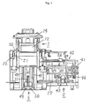
FIG. 1 is a front view of the molding machine of an embodiment of the present invention. -
FIG. 2 is a front view, partly in cross section, of the molding machine ofFIG. 1 . -
FIG. 3 is a top view of the molding machine ofFIG. 1 . -
FIG. 4 is a right-side view of the molding machine ofFIG. 1 . -
FIG. 5 is a top view of the molding machine ofFIG. 1 with a pair of mold cavities defined by the molding machine and related elements. -
FIG. 6 is a front view, partly in cross section, of the molding machine ofFIG. 1 with a pair of mold cavities defined by the molding machine and related elements. -
FIGS. 7 (A) - (D) illustrate the continuous process of molding a pair of molds with the molding machine ofFIG.1 . -
FIGS.8 (A)- (D) illustrate the continuous process of removing a match plate from a pair of flasks with the molding machine ofFIG.1 . -
FIGS.9 (A), (B), and (C) illustrate the continuous process of stripping a pair of molds from a pair of flasks with the molding machine ofFIG.1 . -
FIGS. 1 to 4 show one embodiment of the flaskless molding machine of the present invention. The flaskless molding machine generally includes a main unit 1 on amachinery mount 20 of the machine, a shuttle 2 (FIG. 3 ) for carrying in and carrying out a match plate 11 (FIG. 2 ) between ancope flask 12 and adrag flask 13 of the main unit 1, and amold stripping equipment 3 for stripping the resulting upper and lower molds that are molded in the main unit 1 from the cope and thedrag flasks match plate 11 are mount with patterns. - On the molding machine of the present invention, first the main unit 1 of it will be described. As is best shown in
FIG. 2 , the main unit 1 includes the cope flask (a first flask) 12 and the drag flask (a second flask) 3, which can clamp and hold thematch plate 11 therebetween, anupper squeeze member 14 that is insertable in the cope flask to oppose the upper plane of thematch plate 11, afilling frame 15 that is attached to themachinery mount 20 in its vertical position, and alower squeeze member 16. The squeeze plane of thelower squeeze member 16 is oriented horizontally such that it is insertable into thefilling frame 15. -
FIG.2 illustrates the initial state of the main unit 1. In this state, thematch plate 11, thecope flask 12, thedrag flask 13, and theupper squeeze member 14 are in their horizontal positions, where the squeeze plane of theupper squeeze member 14 is oriented to point downward in the vertical direction. Thematch plate 11, thecope flask 12, thedrag flask 13, and theupper squeeze member 14 can be rotated to their vertical positions in unison, as described in more detail below. - In contrast, neither the
filling frame 15 nor thelower squeeze member 16 can be rotated, and thus they are oriented and attached horizontally. Thefilling frame 15 is attached to the position in which it abuts thedrag flask 13 when thecope flask 12, thedrag flask 13,and thematch plate 11 sandwiched therebetween, have been rotated in their vertical positions. Thelower squeeze member 16 can be inserted into thedrag flask 13 in its vertical position through thefilling frame 15. - Arranged in the upper-center part of the main unit 1 is a
sand supplying device 17 for filling molding sand into a pair of mold cavities to be defined below thesand supplying device 17. (In the state as inFIGS. 1 and2 , the mold cavities have not yet been defined.) - Below and near the
sand supplying device 17, a pair of first, transverse, cylinders (upper cylinders) 18 (shown inFIGS. 1 ,3 , and4 ) and a second, transverse, cylinder (a lower cylinder) 19 are opposed and arranged such that they operate the corresponding upper andlower squeeze members second cylinders - As shown in
FIGS. 1 and2 , arotating axis 21 is arranged at the upper right on themachinery mount 20 and extended in the crosswise direction of a main unit 1 (the normal line againstFIGS. 1 and2 ). Therefore, therotating axis 21 is just shown with its forward end inFIGS. 1 and2 . The rotatingaxis 21 is rotatably mounted in a pair of bearings 22 (just a front bearing 22 is shown inFIG. 1 ), which are mounted on themachinery mount 20 at a predetermined interval therebetween in the crosswise direction. Attached at about the center of the length, therotating axis 21 is apivotable frame 23, which is extended substantially vertically. - As best shown in
FIG. 2 , thedrag flask 13, which left wall has holes to fill molding sand, is mounted on the bottom of the right side of the pivotingframe 23 via a supporting member 24. - On the right side of the
pivoting frame 23, a pair of guide rods 25 (FIGS. 1 and2 illustrate just the front guide rod 25) is attached at a predetermined interval therebetween in the crosswise direction such that they extend substantially vertically. - As shown in
FIG. 2 , acarrier plate 26, on which thematch plate 11 will be placed, is slidably supported on thevertical guide rods 25 via aguide holder 27 above thedrag flask 13. Above thecarrier plate 26, the copeflask 12,whose left wall has holes to fill molding sand, is also slidably supported on thevertical guide rods 25 via aguide holder 28. Thecarrier plate 26 is moveably supported on aguide rail 30, which is extended in the crosswise direction of the machine. Theguide rail 30 can be moved up and down by a telescopic motion of athird cylinder 29 mounted on the pivotingframe 23. The copeflask 12 is attached to a fourth, downwardly moving,cylinder 31 via a supporting member (not shown). The distal end of the piston rod of thefourth cylinder 31 is attached to the pivotingframe 23 such that the copeflask 12 can be moved forward and backward relative to thecarrier plate 26 by a telescopic motion of thefourth cylinder 31. - As shown in
FIG. 1 , a pair offifth cylinders 32 is mounted on the center positions on both sides of the cope flask (just the front side of it is shown inFIG. 1 ). Theupper squeeze member 14 is suspended between the distal ends of the piston rods of thefifth cylinders 32 such that theupper squeeze member 14 can be moved forward and backward relative to the copeflask 12 by telescopic motions of thefifth cylinders 32. Thefifth cylinders 32 thus can be rotated in unison with the copeflask 12 and theupper squeeze member 14. - Mounted on the corners of the back and front sides of the cope
flask 12 are two pairs of sixth, downwardly-facing,cylinders 33. They push away the copeflask 12 from thematch plate 11. Mounted on the back and front sides of the drag flask 13 (FIG. 2 ) are four of seventh, upwardly-moving,cylinders 53. They push away thedrag flask 13 from thematch plate 11. Alternatively, two of theseventh cylinders 53 may be omitted by replacing their functions with those of thethird cylinder 29. Mounted on the front and rear sides of the upper plane of themachinery mount 20 is a pair of eighth, right-facing,cylinders 34. The upper part of the pivotingframe 23 is coupled between the distal ends of the piston rods of theeighth cylinders 34 via acoupling mechanism 35 such that the pivotingframe 23 pivotingly moves up and down about the rotatingaxis 21 by a telescopic motion of the eightcylinders 34. - The filling
device 17 of the main unit 1 is located on themachinery mount 20 between the pair of the eightcylinders 34, as shown inFIG. 1 . As shown inFIG. 2 , attached below asand tank 36 of the fillingdevice 17 is a blowingnozzle 37 for supplying compressed air to fluidize molding sand. -
FIG. 5 (the plane view) andFIG. 6 (the front elevational view) illustrate the arrangement wherein thematch plate 11, the cope and dragflasks lower squeeze members frame 15, define the upper and lower mold cavities in the state shown inFIGS. 1 and2 , as in the above-described manner. Thus the mold cavities and their associated elements are rotated immediately beneath the fillingdevice 17. InFIGS. 5 and6 , asupport framework 38, which plane cross section forms a substantially "C" shape, is installed in a machinery mount 20 (FIGS. 1 and2 ) under the filling device 17 (FIG.6 ). - As best shown in
FIG. 5 , the fillingframe 15 in its vertical position is fixed to the inside of a left-side frame of thesupport framework 38 such that the fillingframe 15 will abut thedrag flask 13 when the lower mold cavity is defined. The secondsingle cylinder 19, which is mentioned above, is mounted on the center portion of the left-side frame of thesupport frame unit 38 such that thesecond cylinder 19 faces rightward. The distal end of the piston rod of thesecond cylinder 19 is fixed to thelower squeeze member 16 in its vertical position. Eachfirst cylinder 18, which is mentioned above, is mounted on a pair of the open ends of thesupport frame 38 such that eachfirst cylinder 18 faces left. - The
shuttle 2 of the molding machine of the present invention will now be described. Theshuttle 2 is located behind the main unit 1 shown inFIGS. 1 and2 . - As shown in
FIG. 4 (the right-side view of the molding machine), theshuttle 2 includes a rail 39 for leading thecarrier plate 26 for the match plate 11 (FIG. 2 ) into a space between the copeflask 12 and thedrag flask 13. Theshuttle 2 also includes two horizontal tie bars 40. They extend forward and backward (this corresponds to the lateral direction inFIG. 4 ) of the machine. They are mounted on themachinery mount 20 of the main unit 1 with a predetermined interval therebetween in the vertical direction under the rail 39. Theshuttle 2 also includes aconnector 42 for detachably connectingrails 41 to thecarrier plate 26. - The
shuttle 2 also includes a driving mechanism 43 for reciprocately moving therails 41 along the tie bars 40. The driving mechanism 43 includes a driver 45 having a pivoting arm 44 that can pivot forward and backward. The distal end of the pivoting arm 44 is supported on theroller 46. Theroller 46 is received in between the pair ofrails 41. By driving the driver 45 the reciprocating and pivoting motion of the pivoting arm 44 causes thecarrier plate 26 to reciprocately move forward and backward via therails 41. Alternatively, theroller 46 and rails 41 may be replaced by any sliding members. - The
mold stripping equipment 3, for stripping the flasks of the molding machine of the invention, will now be described. Themold stripping equipment 3 is arranged at the lower-right part inFIGS. 1 and2 . - As shown in
FIG.4 , themold stripping equipment 3 has two vertical guide rods 47, which are mounted on the base of themachinery mount 20 at a predetermined interval in the crosswise direction (this corresponds to the lateral direction inFIG.4 ) of the machine. Aframe 49 that moves up and down is slidably mounted on the vertical guide rods 47. Suspended from themachinery mount 20 is a pair of ninth, downwardly-facing,cylinders 48, whose piston rods are attached to theframe 49 that moves up and down so as to move it up or down by contracting theninth cylinders 48. - Located above the
frame 49 that moves up and down of themold stripping equipment 3 is areceiver 50 for receiving the stacked upper and lower molds, which are stripped from the stacked cope and dragflasks receiver 50 is supported on the distal end of the piston rod of a tenth, upwardly-facing,cylinder 51 mounted on theframe 49 that moves up and down. Thereceiver 50 thus further rises by the expansion of thetenth cylinder 51 after thereceiver 50 and theframe 49 that moves up and down have been raised in unison by the contraction of theninth cylinders 48. Themold stripping equipment 3 also includes anextruder 52 for extruding the stacked upper and lower molds onto thereceiver 50. - By referring to
FIGS. 7 ,8 , and9 , the procedure will now be explained for molding an upper flaskless mold and a lower flaskless mold in their stacked state as shownFIGS. 1 and2 , using the molding machine as shown inFIGS. 1-6 of the present invention. - First, the fourth, downwardly-facing,
cylinder 31 of the main unit 1 is contracted such that thedrag flask 13, thematch plate 11, and the copeflask 12 overlap in this order in their horizontal positions. Consequently, thematch plate 11 is sandwiched and held between the copeflask 12 and the drag flask 13 (FIG. 7 (A) ). - The
first cylinder 18 of the main unit 1 is then contracted, while the pair of the eightcylinders 34 of the main unit 1 are extended to rotate the pivotingframe 23 clockwise about the rotatingaxis 21. Consequently, the copeflask 12 and thedrag flask 13, with thematch plate 11 sandwiched therebetween, and theupper squeeze member 14, are transported between thefirst cylinder 18 and the fillingframe 15 in their vertical positions . Simultaneously with this rotation, or pivoting motion, thesecond cylinder 19 is extended in a predetermined range, and the pair of thefifth cylinders 32 is contracted, to begin defining the upper and lower mold cavities as shown inFIG. 5 . More particularly, at the state where the copeflask 12 and thedrag flask 13 sandwich and hold thematch plate 11 therebetween, theupper squeeze member 14 is inserted in the copeflask 12 opposite thematch plate 11, and thus the upper mold cavity is defined. Because the copeflask 12 and thedrag flask 13, with thematch plate 11 sandwiched therebetween, theupper squeeze member 14, and the associatedfifth cylinders 32 for driving it, can be rotated in unison, the upper mold cavity can be defined during its rotating motion. At the same time as this rotating motion occurs, thesecond cylinder 19 is extended such that thelower squeeze member 16 is inserted through the fillingframe 15 and the approachingdrag flask 13. Its approaching is caused by the rotating motion in its substantially vertical position. The lower mold cavity is also defined when the rotating motion has been completed and thus thedrag flask 13 abuts the filling frame 15 (FIG. 7 (B) ). This means that the time required for defining the mold cavities and thus for molding molds can be considerably shortened compared to the conventional molding machine. - Compressed air is then supplied from a source (not shown) into the
injector 37, which injects the air for fluidizing the molding sand, of thesand tank 36, to fill the upper and lower mold cavities with the molding sand by means of the injected air (FIG. 7(C) ). Preferably, but not a limiting aspect of the present invention, to shorten the time needed to fill the mold cavities with the molding sand, the compressed air may also be introduced in thesand tank 36 during the filling of the molding sand. - The
first cylinders 18 and thesecond cylinders 19 are then extended to move theupper squeeze member 14 and thelower squeeze member 16 into thematch plate 11 to squeeze the molding sand within the upper and lower mold cavities (FIG.7 (D) ). This squeezing process molds an upper mold and a lower mold within the upper and lower mold cavities. - The
eighth cylinders 34 are then contracted to swivel the pivotingframe 23 counterclockwise, to transfer the copeflask 12 and thedrag flask 13, which are contained within the corresponding upper mold and the corresponding lower mold, to the mold stripping equipment 3 (FIG. 8(A) ). - The
fourth cylinder 31 is then contracted to lift the copeflask 12, while thesixth cylinders 33 are extended to push away thematch plate 11 from the copeflask 12. At the same time, theseventh cylinders 53 are extended to push away thematch plate 11 from the drag flask 13 (FIG. 8(B) ). In this step, preferably the increasing velocity of the copeflask 12 caused by the contraction of thefourth cylinder 31 is about twice the velocity of the separation, in which thematch plate 11 is separated from thedrag flask 13 by the extensions of the sixth andseventh cylinders match plate 11 is separated from the copeflask 12, being able to be substantially the same as that in which thematch plate 11 is separated from thedrag flask 13. - The driver 45 of the driving mechanism 43 is then operated to reversely rotate the pivoting arm 44 such that the
rail 41 and thecarrier plate 26 reciprocatingly move crosswise to remove thematch plate 11 from between the copeflask 12 and drag flask 13 (FIG. 8(C) ). - The
ninth cylinders 48 of themold stripping equipment 3 are then contracted to raise theframe 49 that goes up and down, to raise thetenth cylinder 51, and to raise the associated parts (FIG. 8(D) ). Prior to this raising step, a core may be manually set in the mold within thedrag flask 13 by an operator, if desired, as diagrammatically illustrated inFIG. 8(D) . - The
fourth cylinder 31 is then contracted to lower the copeflask 12 so as to stack it on thedrag flask 13. Thetenth cylinder 51 of themold stripping equipment 3 is then extended to raise thetray 50 so as to have it abut the bottom of the drag flask 13 (FIG. 9(A) ). - The
fifth cylinders 32 are then contracted so as to pressurize push downward the mold within the copeflask 12 by means of theupper squeeze member 14, while thetenth cylinder 51 is contracted. Theninth cylinders 48 are then extended to lower thetray 50 to pull out the upper mold and the lower mold from the copeflask 12 and thedrag flask 13. Thefifth cylinders 32 are then extended to raise the upper squeeze member 14 (FIG.9(B) ). - The
extruder 52 is then operated to push out the stacked upper and lower molds onto the tray 50 (FIG.9(C) ). Consequently, the stacked, flaskless upper and lower molds are obtained. - Although the present invention has been described herein with reference to an exemplary embodiment, the invention is not intended to be limited to the particulars disclosed herein. Those skilled in the art will recognize that many variations or modifications can be made within the spirit and scope of the present invention, which is defined by the appended claims.
Claims (10)
- A molding machine to mold a pair of flaskless molds, comprising:a first flask and a second flask;an exchangeable match plate having a first face and a second face corresponding to the first flask and the second flask respectively, wherein said match plate is adapted to be held between the first flask and the second flask in a sandwich relationship;means for relatively moving either or both of the first flask and the second flask to said match plate such that the first and second flasks can hold and release said match plate being held therebetween;a first squeeze member having a first pressure-applying plane, wherein the first squeeze member is insertable into the first flask while the first pressure-applying plane is opposed to the first face of said match plate, and wherein the first squeeze member is inserted into the first flask when the first flask and the second flask hold said match plate therebetween in a sandwich relationship to define a first mold cavity by the first pressure-applying plane, the first face of the match plate, and the first flask;supporting means for supporting the first flask, the second flask, said match plate, and the first squeeze member, and for rotating them in unison between a horizontal position in which the first flask and the second flask hold said match plate therebetween in the sandwich relationship while the first pressure-applying plane of the first squeeze member is oriented vertically and facing downward and a vertical position in which the first pressure-applying plane is oriented horizontally;a filling frame located to abut the second flask in a perpendicular position of said filling frame when the first and second flasks hold said match plate therebetween in the sandwich relationship at said vertical position;a second squeeze member having a second pressure-applying plane that is oriented horizontally, wherein the second squeeze member is insertable into said filling frame, and wherein the second squeeze member is insertable into the second flask through said filling frame when the first and second flasks hold said match plate therebetween while the second pressure-applying plane is opposed to the second face of said match plate at said vertical position to define a second mold cavity by the second pressure-applying plane, the second face of said match plates, said filling frame, and the second flask;a first actuator to move the first squeeze member to the first faces of said match plates such that molding sand within the first mold cavity is squeezed by the first pressure-applying plane of said inserted first squeeze member; anda second actuator to move the second squeeze member to the second face of said match plate such that molding sand within the second mold cavity is squeezed by the second pressure-applying plane of the second squeeze member.
- The molding machine of claim 1,wherein the first flask is an cope flask and the second flask is a drag flask.
- The molding machine of claim 2,wherein the first mold cavity is defined by the first pressure-applying plane of the first squeeze member, the first face of said match plate, and the first flask, while the first and second flasks, said match plate, and the first squeeze member are rotated from said horizontal position to said vertical position.
- The molding machine of claim 3, wherein the second squeeze member initiates the insertion into said filling frame while said rotation from said horizontal position to said vertical position is carried out, and wherein the second mold cavity is defined by the second pressure-applying plane of the second squeeze member, the second face of said match plate, and the second flask when said filling frame abuts the second flask.
- A molding machine of any one of claims 2, 3, and 4, wherein the first and second actuators include a hydraulic cylinder or an electrical cylinder.
- A molding machine of any one of claims 2 to 5, wherein the first and second flasks have sand filling ports on their side walls for supplying molding sand, and wherein said molding machine further includes means for introducing by air the molding sand into said defined first and second mold cavities through said sand filling ports.
- The molding machine of claim 6, wherein said means for introducing the molding sand includes a fluidizing mechanism for fluidizing the molding sand with an airflow of compressed air.
- A molding machine of any one of claims 2 to 7, wherein it further comprises a shuttle for carrying in and carrying out said match plate between the first flask and the second flask at said horizontal position.
- A molding machine of any one of claims 2 to 8, wherein it further comprises means for stripping a pair of the molds from the first and second flasks.
- A molding machine of claim 9, wherein said means for stripping a pair of the molds includes means for pushing out the molds from the first flask and the second flask, which are in a stacked relationship and which contain a pair of the flaskless molds.
Applications Claiming Priority (1)
| Application Number | Priority Date | Filing Date | Title |
|---|---|---|---|
| JP2006339533 | 2006-12-18 |
Publications (2)
| Publication Number | Publication Date |
|---|---|
| EP1935533A1 true EP1935533A1 (en) | 2008-06-25 |
| EP1935533B1 EP1935533B1 (en) | 2010-06-02 |
Family
ID=38520052
Family Applications (1)
| Application Number | Title | Priority Date | Filing Date |
|---|---|---|---|
| EP07011273A Active EP1935533B1 (en) | 2006-12-18 | 2007-06-08 | Molding machine |
Country Status (12)
| Country | Link |
|---|---|
| US (1) | US8251124B2 (en) |
| EP (1) | EP1935533B1 (en) |
| JP (1) | JP4502077B2 (en) |
| KR (1) | KR101046487B1 (en) |
| CN (1) | CN101563178B (en) |
| AT (1) | ATE469712T1 (en) |
| BR (1) | BRPI0721158B1 (en) |
| DE (2) | DE102007026537A1 (en) |
| DK (1) | DK1935533T3 (en) |
| ES (1) | ES2347083T3 (en) |
| MX (1) | MX2009006524A (en) |
| WO (1) | WO2008075474A1 (en) |
Families Citing this family (8)
| Publication number | Priority date | Publication date | Assignee | Title |
|---|---|---|---|---|
| CN102632204B (en) * | 2012-04-28 | 2013-11-20 | 许云东 | Molding device and method for molding by molding sand |
| CN105798242B (en) * | 2016-04-19 | 2019-01-08 | 殷风平 | A kind of cast iron floor Special moulding machine |
| CN108655350A (en) * | 2017-03-29 | 2018-10-16 | 河北犇创机电设备制造有限公司 | A kind of double-station horizontal parting device |
| CN107321934B (en) * | 2017-06-26 | 2023-05-26 | 江苏盐电铸业有限公司 | Sand molding production system is gone into in resin sand casting |
| CN107321935B (en) * | 2017-06-26 | 2023-01-31 | 江苏盐电铸业有限公司 | Resin sand casting molding system |
| CN110788285A (en) * | 2019-11-28 | 2020-02-14 | 德林智能科技有限公司 | Double-station full-automatic molding machine and using method thereof |
| CN113278866A (en) * | 2021-04-28 | 2021-08-20 | 中航上大高温合金材料股份有限公司 | Preparation method of ferritic stainless steel for stopper rod |
| CN117047047B (en) * | 2023-10-12 | 2024-01-23 | 靖江市晟丰电气机械制造有限公司 | Auto-parts production casting equipment |
Citations (6)
| Publication number | Priority date | Publication date | Assignee | Title |
|---|---|---|---|---|
| JPH0466245A (en) | 1990-06-29 | 1992-03-02 | Tokyu Kk | Molding machine |
| EP0836900A1 (en) | 1996-04-05 | 1998-04-22 | Sintokogio, Ltd. | Method of supplying sand to blow head of blow type molding machine |
| EP1161319B1 (en) * | 1999-02-23 | 2002-08-07 | Disa Industries A/S | Machine for producing flaskless moulds |
| EP1695776A1 (en) * | 2003-12-18 | 2006-08-30 | Sintokogio, Ltd. | Method and device for forming flaskless cope and drag, and method of replacing matchplate |
| EP1726382A1 (en) * | 2004-03-18 | 2006-11-29 | Sintokogio, Ltd. | Method of forming molding-flask-less, upper and lower molds and device therefor |
| EP1837099A2 (en) * | 2006-12-06 | 2007-09-26 | Sintokogio, Ltd. | Moulding machine for making an upper and a lower mould and method for operating said machine |
Family Cites Families (9)
| Publication number | Priority date | Publication date | Assignee | Title |
|---|---|---|---|---|
| US3828840A (en) * | 1972-03-10 | 1974-08-13 | Pettibone Corp | Cyclicly-operable machine adapted to produce and assemble cope and drag mold parts |
| JPS5973148A (en) * | 1982-10-19 | 1984-04-25 | Toyoda Autom Loom Works Ltd | Flaskless type mold forming device |
| JP2772859B2 (en) * | 1990-07-27 | 1998-07-09 | 新東工業株式会社 | Frameless mold making machine |
| CN100376344C (en) * | 2000-04-21 | 2008-03-26 | 新东工业株式会社 | Molding machine and a pattern carrier used therefor |
| EP1433548B1 (en) * | 2001-08-06 | 2017-11-29 | Sintokogio, Ltd. | Method and system for monitoring a molding machine |
| JP4274838B2 (en) * | 2002-04-25 | 2009-06-10 | 株式会社日本触媒 | Cement admixture and method for producing the same |
| KR100863104B1 (en) * | 2004-04-28 | 2008-10-13 | 신토고교 가부시키가이샤 | Method of squeezing foundry sand, match plate, and upper and lower flasks |
| JP2006326590A (en) * | 2005-05-23 | 2006-12-07 | Sintokogio Ltd | Remote monitoring system for mold making apparatus |
| EP1857200B1 (en) * | 2007-05-25 | 2010-10-06 | Sintokogio, Ltd. | Flaskless molding machine |
-
2007
- 2007-06-08 AT AT07011273T patent/ATE469712T1/en not_active IP Right Cessation
- 2007-06-08 DE DE102007026537A patent/DE102007026537A1/en not_active Ceased
- 2007-06-08 EP EP07011273A patent/EP1935533B1/en active Active
- 2007-06-08 DK DK07011273.5T patent/DK1935533T3/en active
- 2007-06-08 DE DE602007006892T patent/DE602007006892D1/en active Active
- 2007-06-08 ES ES07011273T patent/ES2347083T3/en active Active
- 2007-06-22 BR BRPI0721158A patent/BRPI0721158B1/en active IP Right Grant
- 2007-06-22 MX MX2009006524A patent/MX2009006524A/en active IP Right Grant
- 2007-06-22 JP JP2009518666A patent/JP4502077B2/en active Active
- 2007-06-22 CN CN2007800465702A patent/CN101563178B/en active Active
- 2007-06-22 US US12/516,647 patent/US8251124B2/en active Active
- 2007-06-22 WO PCT/JP2007/063058 patent/WO2008075474A1/en active Application Filing
- 2007-06-22 KR KR1020097014051A patent/KR101046487B1/en active IP Right Grant
Patent Citations (6)
| Publication number | Priority date | Publication date | Assignee | Title |
|---|---|---|---|---|
| JPH0466245A (en) | 1990-06-29 | 1992-03-02 | Tokyu Kk | Molding machine |
| EP0836900A1 (en) | 1996-04-05 | 1998-04-22 | Sintokogio, Ltd. | Method of supplying sand to blow head of blow type molding machine |
| EP1161319B1 (en) * | 1999-02-23 | 2002-08-07 | Disa Industries A/S | Machine for producing flaskless moulds |
| EP1695776A1 (en) * | 2003-12-18 | 2006-08-30 | Sintokogio, Ltd. | Method and device for forming flaskless cope and drag, and method of replacing matchplate |
| EP1726382A1 (en) * | 2004-03-18 | 2006-11-29 | Sintokogio, Ltd. | Method of forming molding-flask-less, upper and lower molds and device therefor |
| EP1837099A2 (en) * | 2006-12-06 | 2007-09-26 | Sintokogio, Ltd. | Moulding machine for making an upper and a lower mould and method for operating said machine |
Also Published As
| Publication number | Publication date |
|---|---|
| CN101563178B (en) | 2011-06-08 |
| KR101046487B1 (en) | 2011-07-04 |
| ATE469712T1 (en) | 2010-06-15 |
| DK1935533T3 (en) | 2010-09-20 |
| ES2347083T3 (en) | 2010-10-25 |
| US8251124B2 (en) | 2012-08-28 |
| EP1935533B1 (en) | 2010-06-02 |
| WO2008075474A1 (en) | 2008-06-26 |
| BRPI0721158B1 (en) | 2016-06-28 |
| JP4502077B2 (en) | 2010-07-14 |
| JP2010512246A (en) | 2010-04-22 |
| DE602007006892D1 (en) | 2010-07-15 |
| BRPI0721158A2 (en) | 2013-03-26 |
| US20100071867A1 (en) | 2010-03-25 |
| KR20090094456A (en) | 2009-09-07 |
| MX2009006524A (en) | 2009-06-30 |
| DE102007026537A1 (en) | 2007-11-29 |
| CN101563178A (en) | 2009-10-21 |
Similar Documents
| Publication | Publication Date | Title |
|---|---|---|
| US8251124B2 (en) | Molding machine | |
| KR101086998B1 (en) | Flask unit, cope and drag molding device, and molding line | |
| EP1857200B1 (en) | Flaskless molding machine | |
| EP1880781B1 (en) | Flaskless molding method | |
| EP1897634B1 (en) | Apparatus for molding molding flask-free upper casting mold and lower casting mold | |
| US20150367407A1 (en) | Molding flask for a molding machine and a molding process using the molding flask | |
| EP1897635B1 (en) | A method for making flaskless upper and lower molds, an apparatus therefor, and a method for placing a core. | |
| KR20070006844A (en) | Method of forming molding-flask-less, upper and lower molds and device therefor | |
| KR101110929B1 (en) | Method of replacing match plate in molding apparatus for cope and drag without flask | |
| US7891404B2 (en) | Machine for producing flaskless molds | |
| CN211679894U (en) | Host machine for double-station automatic molding machine | |
| RU2354491C2 (en) | Casting-box for moulding machine and moulding method using casting-box | |
| JPH08132179A (en) | Molding apparatus and molding method |
Legal Events
| Date | Code | Title | Description |
|---|---|---|---|
| PUAI | Public reference made under article 153(3) epc to a published international application that has entered the european phase |
Free format text: ORIGINAL CODE: 0009012 |
|
| 17P | Request for examination filed |
Effective date: 20071022 |
|
| AK | Designated contracting states |
Kind code of ref document: A1 Designated state(s): AT BE BG CH CY CZ DE DK EE ES FI FR GB GR HU IE IS IT LI LT LU LV MC MT NL PL PT RO SE SI SK TR |
|
| AX | Request for extension of the european patent |
Extension state: AL BA HR MK RS |
|
| 17Q | First examination report despatched |
Effective date: 20080801 |
|
| AKX | Designation fees paid |
Designated state(s): AT BE BG CH CY CZ DE DK EE ES FI FR GB GR HU IE IS IT LI LT LU LV MC MT NL PL PT RO SE SI SK TR |
|
| GRAP | Despatch of communication of intention to grant a patent |
Free format text: ORIGINAL CODE: EPIDOSNIGR1 |
|
| GRAS | Grant fee paid |
Free format text: ORIGINAL CODE: EPIDOSNIGR3 |
|
| GRAA | (expected) grant |
Free format text: ORIGINAL CODE: 0009210 |
|
| AK | Designated contracting states |
Kind code of ref document: B1 Designated state(s): AT BE BG CH CY CZ DE DK EE ES FI FR GB GR HU IE IS IT LI LT LU LV MC MT NL PL PT RO SE SI SK TR |
|
| REG | Reference to a national code |
Ref country code: GB Ref legal event code: FG4D |
|
| REG | Reference to a national code |
Ref country code: CH Ref legal event code: EP |
|
| REG | Reference to a national code |
Ref country code: IE Ref legal event code: FG4D |
|
| REF | Corresponds to: |
Ref document number: 602007006892 Country of ref document: DE Date of ref document: 20100715 Kind code of ref document: P |
|
| REG | Reference to a national code |
Ref country code: DK Ref legal event code: T3 |
|
| REG | Reference to a national code |
Ref country code: NL Ref legal event code: VDEP Effective date: 20100602 |
|
| REG | Reference to a national code |
Ref country code: ES Ref legal event code: FG2A Ref document number: 2347083 Country of ref document: ES Kind code of ref document: T3 |
|
| PG25 | Lapsed in a contracting state [announced via postgrant information from national office to epo] |
Ref country code: LT Free format text: LAPSE BECAUSE OF FAILURE TO SUBMIT A TRANSLATION OF THE DESCRIPTION OR TO PAY THE FEE WITHIN THE PRESCRIBED TIME-LIMIT Effective date: 20100602 Ref country code: SE Free format text: LAPSE BECAUSE OF FAILURE TO SUBMIT A TRANSLATION OF THE DESCRIPTION OR TO PAY THE FEE WITHIN THE PRESCRIBED TIME-LIMIT Effective date: 20100602 |
|
| LTIE | Lt: invalidation of european patent or patent extension |
Effective date: 20100602 |
|
| PG25 | Lapsed in a contracting state [announced via postgrant information from national office to epo] |
Ref country code: AT Free format text: LAPSE BECAUSE OF FAILURE TO SUBMIT A TRANSLATION OF THE DESCRIPTION OR TO PAY THE FEE WITHIN THE PRESCRIBED TIME-LIMIT Effective date: 20100602 Ref country code: SI Free format text: LAPSE BECAUSE OF FAILURE TO SUBMIT A TRANSLATION OF THE DESCRIPTION OR TO PAY THE FEE WITHIN THE PRESCRIBED TIME-LIMIT Effective date: 20100602 Ref country code: LV Free format text: LAPSE BECAUSE OF FAILURE TO SUBMIT A TRANSLATION OF THE DESCRIPTION OR TO PAY THE FEE WITHIN THE PRESCRIBED TIME-LIMIT Effective date: 20100602 Ref country code: FI Free format text: LAPSE BECAUSE OF FAILURE TO SUBMIT A TRANSLATION OF THE DESCRIPTION OR TO PAY THE FEE WITHIN THE PRESCRIBED TIME-LIMIT Effective date: 20100602 |
|
| PG25 | Lapsed in a contracting state [announced via postgrant information from national office to epo] |
Ref country code: PL Free format text: LAPSE BECAUSE OF FAILURE TO SUBMIT A TRANSLATION OF THE DESCRIPTION OR TO PAY THE FEE WITHIN THE PRESCRIBED TIME-LIMIT Effective date: 20100602 Ref country code: CY Free format text: LAPSE BECAUSE OF FAILURE TO SUBMIT A TRANSLATION OF THE DESCRIPTION OR TO PAY THE FEE WITHIN THE PRESCRIBED TIME-LIMIT Effective date: 20100602 |
|
| PG25 | Lapsed in a contracting state [announced via postgrant information from national office to epo] |
Ref country code: NL Free format text: LAPSE BECAUSE OF FAILURE TO SUBMIT A TRANSLATION OF THE DESCRIPTION OR TO PAY THE FEE WITHIN THE PRESCRIBED TIME-LIMIT Effective date: 20100602 Ref country code: MC Free format text: LAPSE BECAUSE OF NON-PAYMENT OF DUE FEES Effective date: 20100630 Ref country code: GR Free format text: LAPSE BECAUSE OF FAILURE TO SUBMIT A TRANSLATION OF THE DESCRIPTION OR TO PAY THE FEE WITHIN THE PRESCRIBED TIME-LIMIT Effective date: 20100903 Ref country code: EE Free format text: LAPSE BECAUSE OF FAILURE TO SUBMIT A TRANSLATION OF THE DESCRIPTION OR TO PAY THE FEE WITHIN THE PRESCRIBED TIME-LIMIT Effective date: 20100602 |
|
| PG25 | Lapsed in a contracting state [announced via postgrant information from national office to epo] |
Ref country code: BE Free format text: LAPSE BECAUSE OF FAILURE TO SUBMIT A TRANSLATION OF THE DESCRIPTION OR TO PAY THE FEE WITHIN THE PRESCRIBED TIME-LIMIT Effective date: 20100602 Ref country code: SK Free format text: LAPSE BECAUSE OF FAILURE TO SUBMIT A TRANSLATION OF THE DESCRIPTION OR TO PAY THE FEE WITHIN THE PRESCRIBED TIME-LIMIT Effective date: 20100602 Ref country code: RO Free format text: LAPSE BECAUSE OF FAILURE TO SUBMIT A TRANSLATION OF THE DESCRIPTION OR TO PAY THE FEE WITHIN THE PRESCRIBED TIME-LIMIT Effective date: 20100602 Ref country code: PT Free format text: LAPSE BECAUSE OF FAILURE TO SUBMIT A TRANSLATION OF THE DESCRIPTION OR TO PAY THE FEE WITHIN THE PRESCRIBED TIME-LIMIT Effective date: 20101004 Ref country code: IS Free format text: LAPSE BECAUSE OF FAILURE TO SUBMIT A TRANSLATION OF THE DESCRIPTION OR TO PAY THE FEE WITHIN THE PRESCRIBED TIME-LIMIT Effective date: 20101002 |
|
| PLBE | No opposition filed within time limit |
Free format text: ORIGINAL CODE: 0009261 |
|
| STAA | Information on the status of an ep patent application or granted ep patent |
Free format text: STATUS: NO OPPOSITION FILED WITHIN TIME LIMIT |
|
| PG25 | Lapsed in a contracting state [announced via postgrant information from national office to epo] |
Ref country code: MT Free format text: LAPSE BECAUSE OF FAILURE TO SUBMIT A TRANSLATION OF THE DESCRIPTION OR TO PAY THE FEE WITHIN THE PRESCRIBED TIME-LIMIT Effective date: 20100602 Ref country code: IE Free format text: LAPSE BECAUSE OF NON-PAYMENT OF DUE FEES Effective date: 20100608 |
|
| 26N | No opposition filed |
Effective date: 20110303 |
|
| REG | Reference to a national code |
Ref country code: FR Ref legal event code: ST Effective date: 20110228 |
|
| REG | Reference to a national code |
Ref country code: DE Ref legal event code: R097 Ref document number: 602007006892 Country of ref document: DE Effective date: 20110302 |
|
| PG25 | Lapsed in a contracting state [announced via postgrant information from national office to epo] |
Ref country code: FR Free format text: LAPSE BECAUSE OF NON-PAYMENT OF DUE FEES Effective date: 20100802 |
|
| REG | Reference to a national code |
Ref country code: CH Ref legal event code: PL |
|
| GBPC | Gb: european patent ceased through non-payment of renewal fee |
Effective date: 20110608 |
|
| PG25 | Lapsed in a contracting state [announced via postgrant information from national office to epo] |
Ref country code: CH Free format text: LAPSE BECAUSE OF NON-PAYMENT OF DUE FEES Effective date: 20110630 Ref country code: LI Free format text: LAPSE BECAUSE OF NON-PAYMENT OF DUE FEES Effective date: 20110630 |
|
| PG25 | Lapsed in a contracting state [announced via postgrant information from national office to epo] |
Ref country code: GB Free format text: LAPSE BECAUSE OF NON-PAYMENT OF DUE FEES Effective date: 20110608 |
|
| PG25 | Lapsed in a contracting state [announced via postgrant information from national office to epo] |
Ref country code: BG Free format text: LAPSE BECAUSE OF FAILURE TO SUBMIT A TRANSLATION OF THE DESCRIPTION OR TO PAY THE FEE WITHIN THE PRESCRIBED TIME-LIMIT Effective date: 20100602 Ref country code: LU Free format text: LAPSE BECAUSE OF NON-PAYMENT OF DUE FEES Effective date: 20100608 Ref country code: HU Free format text: LAPSE BECAUSE OF FAILURE TO SUBMIT A TRANSLATION OF THE DESCRIPTION OR TO PAY THE FEE WITHIN THE PRESCRIBED TIME-LIMIT Effective date: 20101203 |
|
| PG25 | Lapsed in a contracting state [announced via postgrant information from national office to epo] |
Ref country code: BG Free format text: LAPSE BECAUSE OF FAILURE TO SUBMIT A TRANSLATION OF THE DESCRIPTION OR TO PAY THE FEE WITHIN THE PRESCRIBED TIME-LIMIT Effective date: 20100902 |
|
| PGFP | Annual fee paid to national office [announced via postgrant information from national office to epo] |
Ref country code: ES Payment date: 20160622 Year of fee payment: 10 Ref country code: CZ Payment date: 20160606 Year of fee payment: 10 |
|
| PGFP | Annual fee paid to national office [announced via postgrant information from national office to epo] |
Ref country code: DK Payment date: 20160622 Year of fee payment: 10 |
|
| REG | Reference to a national code |
Ref country code: DK Ref legal event code: EBP Effective date: 20170630 |
|
| PG25 | Lapsed in a contracting state [announced via postgrant information from national office to epo] |
Ref country code: CZ Free format text: LAPSE BECAUSE OF NON-PAYMENT OF DUE FEES Effective date: 20170608 |
|
| PG25 | Lapsed in a contracting state [announced via postgrant information from national office to epo] |
Ref country code: DK Free format text: LAPSE BECAUSE OF NON-PAYMENT OF DUE FEES Effective date: 20170630 |
|
| REG | Reference to a national code |
Ref country code: ES Ref legal event code: FD2A Effective date: 20181116 |
|
| PG25 | Lapsed in a contracting state [announced via postgrant information from national office to epo] |
Ref country code: ES Free format text: LAPSE BECAUSE OF NON-PAYMENT OF DUE FEES Effective date: 20170609 |
|
| PGFP | Annual fee paid to national office [announced via postgrant information from national office to epo] |
Ref country code: DE Payment date: 20230620 Year of fee payment: 17 |
|
| PGFP | Annual fee paid to national office [announced via postgrant information from national office to epo] |
Ref country code: TR Payment date: 20230607 Year of fee payment: 17 |
|
| PGFP | Annual fee paid to national office [announced via postgrant information from national office to epo] |
Ref country code: IT Payment date: 20230623 Year of fee payment: 17 |