EP1934523B1 - Combustion chamber and gas turbine plant - Google Patents
Combustion chamber and gas turbine plant Download PDFInfo
- Publication number
- EP1934523B1 EP1934523B1 EP06793722.7A EP06793722A EP1934523B1 EP 1934523 B1 EP1934523 B1 EP 1934523B1 EP 06793722 A EP06793722 A EP 06793722A EP 1934523 B1 EP1934523 B1 EP 1934523B1
- Authority
- EP
- European Patent Office
- Prior art keywords
- combustion chamber
- burner
- wall
- insert
- burner insert
- Prior art date
- Legal status (The legal status is an assumption and is not a legal conclusion. Google has not performed a legal analysis and makes no representation as to the accuracy of the status listed.)
- Not-in-force
Links
Images

Classifications
-
- F—MECHANICAL ENGINEERING; LIGHTING; HEATING; WEAPONS; BLASTING
- F23—COMBUSTION APPARATUS; COMBUSTION PROCESSES
- F23R—GENERATING COMBUSTION PRODUCTS OF HIGH PRESSURE OR HIGH VELOCITY, e.g. GAS-TURBINE COMBUSTION CHAMBERS
- F23R3/00—Continuous combustion chambers using liquid or gaseous fuel
- F23R3/42—Continuous combustion chambers using liquid or gaseous fuel characterised by the arrangement or form of the flame tubes or combustion chambers
- F23R3/60—Support structures; Attaching or mounting means
-
- F—MECHANICAL ENGINEERING; LIGHTING; HEATING; WEAPONS; BLASTING
- F23—COMBUSTION APPARATUS; COMBUSTION PROCESSES
- F23D—BURNERS
- F23D14/00—Burners for combustion of a gas, e.g. of a gas stored under pressure as a liquid
- F23D14/46—Details, e.g. noise reduction means
- F23D14/72—Safety devices, e.g. operative in case of failure of gas supply
- F23D14/78—Cooling burner parts
-
- F—MECHANICAL ENGINEERING; LIGHTING; HEATING; WEAPONS; BLASTING
- F23—COMBUSTION APPARATUS; COMBUSTION PROCESSES
- F23R—GENERATING COMBUSTION PRODUCTS OF HIGH PRESSURE OR HIGH VELOCITY, e.g. GAS-TURBINE COMBUSTION CHAMBERS
- F23R3/00—Continuous combustion chambers using liquid or gaseous fuel
- F23R3/02—Continuous combustion chambers using liquid or gaseous fuel characterised by the air-flow or gas-flow configuration
- F23R3/04—Air inlet arrangements
- F23R3/10—Air inlet arrangements for primary air
Definitions
- the present invention relates to a combustion chamber, in particular a combustion chamber for a gas turbine plant, comprising a burner and a burner insert surrounding the burner while leaving a gap open towards the interior of the combustion chamber.
- a gas turbine plant with such a combustion chamber.
- a gas turbine plant is a turbomachine that essentially comprises a compressor section, a turbine section and a burner section with one or more combustion chambers arranged between the compressor section and the turbine section.
- ambient air is sucked through the compressor and compressed to an elevated pressure.
- the compressed air is supplied to the burner section, where it is burned by means of a burner in a combustion chamber.
- the combustion exhaust gas which is hot due to combustion and is under high pressure, is finally supplied as a working medium to the turbine section, where it relaxes and cools under power, converting the energy of the working fluid into mechanical work.
- the energy converted in the turbine section in mechanical work serves on the one hand to drive the compressor and on the other hand to drive a consumer, for example a generator for generating electricity.
- premix combustion In modern gas turbine plants mostly the so-called premix combustion is used.
- premix combustion the fuel is first mixed with an oxidant, typically air, before the mixture is ignited.
- pilot fuel mass flow In the premix combustion often comes a separate fuel mass flow used, which is used to stabilize the flame use and is referred to as pilot fuel mass flow.
- the pilot fuel mass flow becomes fed via a separate from the main fuel supply system. It serves to protect the flame from instabilities due to the thermoacoustic behavior of the combustion.
- pilot mixed premix combustion Premix combustion using a pilot gas stream is also called pilot mixed premix combustion.
- piloted premix combustion the NO x emission of the combustion system depends on the amount of pilot mass fuel flow supplied. The lower the pilot fuel mass flow, the lower the NO x emission.
- a combustion chamber with a burner designed for piloted premix combustion is known, for example, in US Pat US 2005/0016178 A1 described.
- the burner is surrounded by a burner insert, wherein between the burner insert and the burner to the combustion chamber interior open annular gap is present.
- the combustion chamber insert comprises a carrier as well as a burner insert wall arranged upstream of the carrier towards the interior of the combustion chamber and simultaneously forming the combustion chamber wall in the region of the burner.
- a cooling air channel is formed between the burner insert wall and the carrier, which is supplied from the outside of the combustion chamber with cooling air. This cooling air channel is sealed against the annular gap between the burner insert and the burner.
- At the end of the burner insert wall remote from the burner there is also an opening to the interior of the combustion chamber, via which the cooling air flowing through the cooling air passage is discharged into the combustion chamber interior.
- Another object of the present invention is to provide an improved gas turbine plant.
- the first object is achieved by a combustion chamber with a burner and a burner insert surrounding the burner according to claim 1.
- the second object by a gas turbine plant according to claim 8.
- a combustion chamber according to the invention is equipped with a burner and a burner insert surrounding the burner.
- the burner may be suitable in particular for pilot-operated premix combustion. Between the burner and the burner insert, a gap open towards the interior of the combustion chamber is left.
- the combustion chamber insert comprises a carrier and a carrier insert wall which precedes the carrier toward the combustion chamber interior and between which a flow channel communicating with a cooling fluid source is formed. The flow channel opens into the gap between the burner and the burner insert and is otherwise sealed against the combustion chamber interior.
- the inventive design of the combustion chamber makes it possible to cool the burner insert wall, which also forms the combustion chamber wall usually used cooling fluid in the gap between the burner and the burner insert. In this way, an introduction of cooling fluid, usually cooling air, take place directly at the burner outlet.
- cooling fluid usually cooling air
- By introducing cooling fluid in the immediate vicinity of the burner outlet into the combustion chamber it is possible to achieve an improvement in the thermoacoustic behavior of the combustion exhaust gases in the combustion chamber. Due to the improved thermoacoustic behavior can be made a reduction in the pilot gas quantity, resulting in a reduction in NO x emissions follows.
- the burner insert wall is usually fastened by means of a rib engaging in a groove of the carrier rib in the region of the flow channel on the carrier.
- the rib in this case has at least one passage opening enabling the passage of cooling fluid, for example at least one bore.
- the carrier has cooling fluid channels, which communicate directly or indirectly with the cooling fluid source and open into the flow channel.
- cooling fluid channels which communicate directly or indirectly with the cooling fluid source and open into the flow channel.
- the combustion chamber according to the invention can in particular be designed as an axially symmetrical annular combustion chamber with a number of burners distributed around the axis of symmetry and at least one burner insert.
- the burner insert wall of a burner insert has at least one abutting edge on which it adjoins a abutting edge of an adjacent burner insert or on a combustion chamber wall.
- a seal is then present, which seals the burner insert wall against the combustion chamber interior. In this way you can prevent that from flowing through the flow channel flowing cooling fluid instead through the gap between the burner and the burner insert flows through gaps between adjacent burner inserts or between a burner insert and the combustion chamber wall into the combustion chamber.
- a gas turbine plant according to the invention is equipped with a combustion chamber according to the invention.
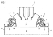
- FIG. 1 A section of a combustion chamber according to the invention is in FIG. 1 shown in a sectional view.
- a burner 1 a burner insert 3, which annularly surrounds the burner 1, and to recognize a part of the combustion chamber wall 5.
- the combustion chamber is arranged in a Brennschplenum 4 and extends annularly around a turbine shaft (not shown).
- the burner 1 is inserted into a receptacle of the burner insert 3.
- the burner insert 3 adjoins the combustion chamber wall 5 and closes off the combustion chamber.
- the burner insert 3 comprises a carrier 7, which is designed as a grooved ring: In this run one or more annular grooves around the burner 1 around, can be supplied to the burner 1 by the cooling air. For better clarity, the grooves are not shown.
- the grooved ring 7 upstream of the combustion chamber interior 2 towards a burner insert wall 9 is present, which at the same time represents the burner 1 surrounding the end wall of the combustion chamber 1.
- the burner insert wall 9 has a circumferential web 23, with which the wall is inserted into a groove 21 of the grooved ring 7 and held there. Through bores 11, 15 in the grooved ring 7, the side of the burner insert wall 9 facing away from the combustion chamber interior 2 can be blown with cooling air in order to effect impingement cooling.
- FIG. 3 The grooved ring 7, the burner insert wall 9 and a section of the combustion chamber wall 5 and a section of the burner 1 are in FIG. 3 shown enlarged. Between the U-ring 7 and the burner insert wall 9, a flow channel 13 is formed, which is supplied from the Brennschplenum 4 fro cooling air as cooling fluid. In this sense, combustor plenum 4 may be considered as a source of cooling fluid.
- the flow paths of the cooling air are in FIG. 3 indicated by arrows.
- a seal 19 is arranged between the abutting edge and the combustion chamber wall 5.
- the seal is preferably flexible in order to compensate for thermal expansions. It can e.g. be made as metal.
- the gap between the burner 1 and the burner insert 3 is sealed by a serving as a seal piston ring 31.
- the cooling air used for cooling the burner insert wall 9 flows into the combustion chamber directly next to the burner outlet 33 through an annular gap 29 and is fed to the combustion process. This improves the thermoacoustic behavior of the combustion chamber and thereby enables a reduction of the supplied pilot fuel quantity and thus to a reduction of the NO x emissions.
- FIG. 2 A top view of the burner insert 3 and the burner 1 seen from the combustion chamber interior is in FIG. 2 shown. Arrows indicate the flow paths of the cooling air along the combustion chamber insert wall 9.
- combustion chamber In the center of the burner insert 3, the burner wall 33 surrounding the burner opening 27 can be seen. Between the burner insert wall 9 and the combustion wall 27 is the annular gap 29 through which the cooling air used for cooling the burner insert wall 9 flows into the combustion chamber interior 2.
- combustion chamber In the FIG. 2 illustrated combustion chamber is an annular combustion chamber, which is arranged axially symmetrically around a turbine rotor.
- the radially outer combustion chamber wall 5A and the radially inner combustion chamber wall 5B can be seen.
- seals 19A and 19B are provided, which seal the flow channel of the combustion chamber insert 3 against the combustion chamber interior 2.
- a separate burner insert 3 is present for each burner 1.
- the burner inserts 3 adjoin one another in the circumferential direction of the combustion chamber. Gaps between opposing abutting edges 17C, 17D of burner insert walls 9 of adjacent burner inserts 3 are also sealed with seals 19C, 19D against the combustion chamber interior to prevent leakage of cooling air through these gaps.
- seals 19C, 19D against the combustion chamber interior to prevent leakage of cooling air through these gaps.
- the air mass flow supplied to the combustion chamber interior 2 through the flow channel 13 corresponds to only a few percent of the air mass flow fed through the burner 1.
- the air mass flow supplied through the flow channel 13 is less than about 5% of the air mass flow supplied by the burner 1.
- combustion chamber can also be designed as an approximately cylindrical combustion chamber with at least one burner and at least one burner insert on the end face of the cylinder.
Description
Die vorliegende Erfindung betrifft eine Brennkammer, insbesondere eine Brennkammer für eine Gasturbinenanlage, mit einem Brenner und einem den Brenner unter Belassung eines zum Brennkammerinneren hin offenen Spaltes umgebenden Brennereinsatz. Daneben betrifft die vorliegende Erfindung eine Gasturbinenanlage mit einer derartigen Brennkammer.The present invention relates to a combustion chamber, in particular a combustion chamber for a gas turbine plant, comprising a burner and a burner insert surrounding the burner while leaving a gap open towards the interior of the combustion chamber. In addition, the present invention relates to a gas turbine plant with such a combustion chamber.
Eine Gasturbinenanlage ist eine Strömungsmaschine, die im Wesentlichen einen Verdichterabschnitt, einen Turbinenabschnitt und einen zwischen dem Verdichterabschnitt und dem Turbinenabschnitt angeordneten Brennerabschnitt mit einer oder mehreren Brennkammern umfasst. Im Betrieb der Gasturbinenanlage wird Umgebungsluft durch den Verdichter angesaugt und auf einen erhöhten Druck verdichtet. Die verdichtete Luft wird dem Brennerabschnitt zugeführt, wo sie mittels eines Brenners in einer Brennkammer verbrannt wird. Das aufgrund der Verbrennung heiße und unter hohem Druck stehende Verbrennungsabgas wird schließlich als ein Arbeitmedium dem Turbinenabschnitt zugeführt, wo es unter Arbeitsleistung entspannt und abkühlt, wobei die Energie des Arbeitsmediums in mechanische Arbeit umgewandelt wird. Die im Turbinenabschnitt in mechanischer Arbeit umgewandelte Energie dient einerseits zum Antreiben des Verdichters und andererseits zum Antreiben eines Verbrauchers, beispielsweise eines Generators zum Erzeugen von Elektrizität.A gas turbine plant is a turbomachine that essentially comprises a compressor section, a turbine section and a burner section with one or more combustion chambers arranged between the compressor section and the turbine section. During operation of the gas turbine plant ambient air is sucked through the compressor and compressed to an elevated pressure. The compressed air is supplied to the burner section, where it is burned by means of a burner in a combustion chamber. The combustion exhaust gas, which is hot due to combustion and is under high pressure, is finally supplied as a working medium to the turbine section, where it relaxes and cools under power, converting the energy of the working fluid into mechanical work. The energy converted in the turbine section in mechanical work serves on the one hand to drive the compressor and on the other hand to drive a consumer, for example a generator for generating electricity.
In modernen Gasturbinenanlagen kommt zumeist die sogenannte Vormischverbrennung zur Anwendung. In der Vormischverbrennung wird der Brennstoff erst mit einem Oxidationsmittel, in der Regel Luft, vermischt, bevor das Gemisch gezündet wird. Bei der Vormischverbrennung kommt häufig auch ein gesonderter Brennstoffmassenstrom zur Anwendung, der zum Stabilisieren der Flamme Verwendung findet und als Pilotbrennstoffmassenstrom bezeichnet wird. Der Pilotbrennstoffmassenstrom wird über ein von der Hauptbrennstoffzufuhr gesondertes Zufuhrsystem zugeleitet. Er dient dazu, die Flamme vor Instabilitäten aufgrund des thermoakustischen Verhaltens der Verbrennung zu bewahren. Eine Vormischverbrennung, in der ein Pilotgassenstrom zur Anwendung kommt wird auch pilotierte Vormischverbrennung genannt. In einer pilotierten Vormischverbrennung hängt die NOx-Emission des Verbrennungssystems von der Menge des zugeführten Pilotbrennstoffmassenstroms ab. Je niedriger der Pilotbrennstoffmassenstrom ist, desto geringer ist auch die NOx-Emission.In modern gas turbine plants mostly the so-called premix combustion is used. In premix combustion, the fuel is first mixed with an oxidant, typically air, before the mixture is ignited. In the premix combustion often comes a separate fuel mass flow used, which is used to stabilize the flame use and is referred to as pilot fuel mass flow. The pilot fuel mass flow becomes fed via a separate from the main fuel supply system. It serves to protect the flame from instabilities due to the thermoacoustic behavior of the combustion. Premix combustion using a pilot gas stream is also called pilot mixed premix combustion. In piloted premix combustion, the NO x emission of the combustion system depends on the amount of pilot mass fuel flow supplied. The lower the pilot fuel mass flow, the lower the NO x emission.
Eine Brennkammer mit einem für eine pilotierte Vormischverbrennung ausgebildeten Brenner ist beispielsweise in
Gegenüber diesem Stand der Technik ist es Aufgabe der vorliegenden Erfindung, eine verbesserte Brennkammer mit einem Brenner und einem den Brenner umgebenden Brennereinsatz zur Verfügung zu stellen.Compared to this prior art, it is an object of the present invention to provide an improved combustion chamber with a burner and a burner insert surrounding the burner.
Eine weitere Aufgabe der vorliegenden Erfindung ist es, eine verbesserte Gasturbinenanlage zur Verfügung zu stellen.Another object of the present invention is to provide an improved gas turbine plant.
Die erste Aufgabe wird durch eine Brennkammer mit einem Brenner und einem den Brenner umgebenden Brennereinsatz nach Anspruch 1 gelöst. Die zweite Aufgabe durch eine Gasturbinenanlage nach Anspruch 8.The first object is achieved by a combustion chamber with a burner and a burner insert surrounding the burner according to claim 1. The second object by a gas turbine plant according to claim 8.
Eine erfindungsgemäße Brennkammer ist mit einem Brenner und einem den Brenner umgebenden Brennereinsatz ausgestattet. Der Brenner kann insbesondere zur pilotierten Vormischverbrennung geeignet sein. Zwischen dem Brenner und dem Brennereinsatz ist ein zum Brennkammerinneren hin offener Spalt belassen. Der Brennkammereinsatz umfasst einen Träger und eine dem Träger zum Brennkammerinneren hin vorgelagerte Brennereinsatzwand, zwischen denen ein mit einer Kühlfluidquelle in Verbindung stehender Strömungskanal gebildet ist. Der Strömungskanal mündet in den Spalt zwischen dem Brenner und dem Brennereinsatz und ist im Übrigen gegen das Brennkammerinnere abgedichtet.A combustion chamber according to the invention is equipped with a burner and a burner insert surrounding the burner. The burner may be suitable in particular for pilot-operated premix combustion. Between the burner and the burner insert, a gap open towards the interior of the combustion chamber is left. The combustion chamber insert comprises a carrier and a carrier insert wall which precedes the carrier toward the combustion chamber interior and between which a flow channel communicating with a cooling fluid source is formed. The flow channel opens into the gap between the burner and the burner insert and is otherwise sealed against the combustion chamber interior.
Die erfindungsgemäße Ausgestaltung der Brennkammer ermöglicht es, zum Kühlen der Brennereinsatzwand, die in der Regel auch die Brennkammerwand bildet, verwendetes Kühlfluid in den Spalt zwischen dem Brenner und den Brennereinsatz einzuleiten. Auf diese Weise kann ein Einbringen von Kühlfluid, in der Regel Kühlluft, unmittelbar am Brennerausgang erfolgen. Durch das Einbringen von Kühlfluid in unmittelbarer Nähe des Brennerausgangs in die Brennkammer lässt sich eine Verbesserung des thermoakustischen Verhaltens der Verbrennungsabgase in der Brennkammer erzielen. Aufgrund des verbesserten thermoakustischen Verhaltens kann eine Absenkung der Pilotgasmenge vorgenommen werden, woraus eine Reduzierung der NOx-Emissionen folgt.The inventive design of the combustion chamber makes it possible to cool the burner insert wall, which also forms the combustion chamber wall usually used cooling fluid in the gap between the burner and the burner insert. In this way, an introduction of cooling fluid, usually cooling air, take place directly at the burner outlet. By introducing cooling fluid in the immediate vicinity of the burner outlet into the combustion chamber, it is possible to achieve an improvement in the thermoacoustic behavior of the combustion exhaust gases in the combustion chamber. Due to the improved thermoacoustic behavior can be made a reduction in the pilot gas quantity, resulting in a reduction in NO x emissions follows.
Im eingangs beschriebenen Stand der Technik ist es hingegen aufgrund der Führung der Kühlluft vom Brenner weg nicht möglich, die Kühlluft in der Nähe der Brenneröffnung in die Brennkammer einzuleiten.In the prior art described above, however, it is not possible due to the leadership of the cooling air away from the burner to introduce the cooling air in the vicinity of the burner opening in the combustion chamber.
Konstruktiv ist die Brennereinsatzwand in der Regel mittels einer im Bereich des Strömungskanals in eine Nut des Trägers eingreifenden Rippe am Träger befestigt. Um den Strömungskanal zum Spalt zwischen dem Brenner und dem Brennereinsatz zu öffnen, weist die Rippe in diesem Fall wenigstens eine den Durchtritt von Kühlfluid ermöglichende Durchgangsöffnung, beispielsweise wenigstens eine Bohrung, auf.Structurally, the burner insert wall is usually fastened by means of a rib engaging in a groove of the carrier rib in the region of the flow channel on the carrier. In order to open the flow channel to the gap between the burner and the burner insert, the rib in this case has at least one passage opening enabling the passage of cooling fluid, for example at least one bore.
In einer weiteren Ausgestaltung der erfindungsgemäßen Brennkammer weist der Träger Kühlfluidkanäle auf, die mittelbar oder unmittelbar mit der Kühlfluidquelle in Verbindung stehen und in den Strömungskanal münden. Es sind jedoch auch konstruktive Ausgestaltungen möglich, welche den Kühlfluidstrom am Träger vorbei in den Strömungskanal leiten. Beide Ausgestaltungen können zudem auch miteinander kombiniert werden.In a further embodiment of the combustion chamber according to the invention, the carrier has cooling fluid channels, which communicate directly or indirectly with the cooling fluid source and open into the flow channel. However, there are also constructive embodiments possible, which guide the cooling fluid flow past the carrier in the flow channel. Both embodiments can also be combined with each other.
Falls der Spalt zwischen dem Brenner und dem Brennereinsatz an keiner Stelle zu einem Brennkammerplenum hin konstruktiv geschlossen ist, ist zwischen dem Brenner und dem Brennereinsatz eine den Spalt zum Brennkammerplenum hin abdichtende Dichtung vorhanden. Dadurch lässt sich verhindern, dass Kühlfluid unter Umgehung des Strömungskanals in den Spalt zwischen Brenner und Brennereinsatz strömt.If the gap between the burner and the burner insert is not structurally closed at any point to a Brennkammerplenum out, a gap to the Brennkammerplenum sealing gasket is present between the burner and the burner insert. This makes it possible to prevent cooling fluid from flowing into the gap between burner and burner insert, bypassing the flow channel.
Die erfindungsgemäße Brennkammer kann insbesondere als axialsymmetrische Ringbrennkammer mit einer Anzahl von um die Symmetrieachse verteilten Brennern und wenigstens einem Brennereinsatz ausgestaltet sein.The combustion chamber according to the invention can in particular be designed as an axially symmetrical annular combustion chamber with a number of burners distributed around the axis of symmetry and at least one burner insert.
In einer weiteren Ausgestaltung der erfindungsgemäßen Brennkammer weist die Brennereinsatzwand eines Brennereinsatzes wenigstens eine Stoßkante auf, an der sie an eine Stoßkante eines benachbarten Brennereinsatzes oder an eine Brennkammerwand angrenzt. Zwischen den Stoßkanten benachbarter Brennereinsätze und/oder zwischen der Stoßkante und der Brennkammerwand ist dann eine Dichtung vorhanden, welche die Brennereinsatzwand gegen das Brennkammerinnere hin abdichtet. Auf diese Weise lässt sich verhindern, dass das durch den Strömungskanal strömende Kühlfluid statt durch den Spalt zwischen dem Brenner und dem Brennereinsatz durch Spalte zwischen benachbarten Brennereinsätzen oder zwischen einem Brenneinsatz und der Brennkammerwand in die Brennkammer strömt.In a further embodiment of the combustion chamber according to the invention, the burner insert wall of a burner insert has at least one abutting edge on which it adjoins a abutting edge of an adjacent burner insert or on a combustion chamber wall. Between the abutting edges of adjacent burner inserts and / or between the abutting edge and the combustion chamber wall, a seal is then present, which seals the burner insert wall against the combustion chamber interior. In this way you can prevent that from flowing through the flow channel flowing cooling fluid instead through the gap between the burner and the burner insert flows through gaps between adjacent burner inserts or between a burner insert and the combustion chamber wall into the combustion chamber.
Eine erfindungsgemäße Gasturbinenanlage ist mit einer erfindungsgemäßen Brennkammer ausgestattet.A gas turbine plant according to the invention is equipped with a combustion chamber according to the invention.
Weitere Merkmale, Eigenschaften und Vorteile der vorliegenden Erfindung ergeben sich aus der nachfolgenden Beschreibung eines Ausführungsbeispiels unter Bezugnahme auf die beiliegenden Figuren.
- FIG 1
- zeigt einen Ausschnitt aus einer erfindungsgemäßen Brennkammer mit einem Brenner und einem Brennereinsatz,
- FIG 2
- zeigt den Brennereinsatz aus
FIG 1 in einer schematischen Draufsicht, - FIG 3
- zeigt einen Ausschnitt aus
FIG 1 im Detail.
- FIG. 1
- shows a section of a combustion chamber according to the invention with a burner and a burner insert,
- FIG. 2
- shows the burner insert
FIG. 1 in a schematic plan view, - FIG. 3
- shows a section
FIG. 1 in detail.
Ein Ausschnitt aus einer erfindungsgemäßen Brennkammer ist in
Der Brennereinsatz 3 umfasst einen Träger 7, der als Nutring ausgebildet ist: In diesem verlaufen eine oder mehrere Ringnuten um den Brenner 1 herum, durch die Kühlluft zum Brenner 1 zugeführt werden kann. Der besseren Übersichtlichkeit halber sind die Nuten nicht eingezeichnet.The
Dem Nutring 7 zum Brennkammerinneren 2 hin vorgelagert ist eine Brennereinsatzwand 9 vorhanden, welche gleichzeitig die den Brenner 1 umgebende Abschlusswand der Brennkammer 1 darstellt. Die Brennereinsatzwand 9 weist einen umlaufenden Steg 23 auf, mit dem die Wand in eine Nut 21 des Nutringes 7 eingesetzt und dort gehalten ist. Durch Bohrungen 11, 15 im Nutring 7 lässt sich die dem Brennkammerinneren 2 abgewandte Seite der Brennereinsatzwand 9 mit Kühlluft anblasen, um eine Prallkühlung zu bewirken.The grooved ring 7 upstream of the
Der Nutring 7, die Brennereinsatzwand 9 sowie ein Ausschnitt der Brennkammerwand 5 und ein Ausschnitt des Brenners 1 sind in
Im Nutring 7 sind Bohrungen 11, 15 vorhanden, durch welche die Brennereinsatzwand 9 mit Kühlluft angeblasen werden kann, um eine Prallkühlung der Brennereinsatzwand 9 zu bewirken. Um zu verhindern, dass die Kühlluft im Bereich der Stoßkante 17, mit der die Brennereinsatzwand 9 an die Brennkammerwand 5 angrenzt, in das Brennkammerinnere 2 strömt, ist eine Dichtung 19 zwischen der Stoßkante und der Brennkammerwand 5 angeordnet. Die Dichtung ist vorzugsweise flexibel, um thermische Dehnungen kompensieren zu können. Sie kann z.B. als Metall hergestellt sein.In the grooved ring 7
Der Steg 23, mit dem die Brennereinsatzwand 9 in der Haltenut 21 des Nutringes 7 gehalten ist, sind Bohrungen 25 vorhanden, die es ermöglichen, dass die Kühlluft auf den Brenner 1 zuströmt. Von der Brennerwand 27 wird die Kühlluft in Richtung auf das Innere der Brennkammer umgelenkt und strömt durch den Ringspalt 29 zwischen der Brennerwand 27 und der Brennereinsatzwand 9 in das Innere 2 der Brennkammer ein.The
Gegen das Brennkammerplenum 4 ist der Zwischenraum zwischen dem Brenner 1 und dem Brennereinsatz 3 durch einen als Dichtung dienender Kolbenring 31 abgedichtet.Against the Brennkammerplenum 4, the gap between the burner 1 and the
In der erfindungsgemäßen Brennkammer strömt die zur Kühlung der Brennereinsatzwand 9 herangezogene Kühlluft unmittelbar neben dem Brennerausgäng 33 durch einen Ringspalt 29 in die Brennkammer ein und wird dem Verbrennungsprozess zugeführt. Dies verbessert das thermoakustische Verhalten der Brennkammer und ermöglicht dadurch eine Verringerung der zugeführten Pilotbrennstoffmenge und damit zu einer Verringerung der NOx-Emissionen.In the combustion chamber according to the invention, the cooling air used for cooling the
Eine Draufsicht auf den Brennereinsatz 3 und den Brenner 1 vom Brennkammerinneren aus gesehen ist in
Im Zentrum des Brennereinsatzes 3 ist die die Brenneröffnung 33 umgebende Brennerwand 27 zu erkennen. Zwischen der Brennereinsatzwand 9 und der Brennwand 27 befindet sich der Ringspalt 29, durch den die zum Kühlen der Brennereinsatzwand 9 verwendete Kühlluft in das Brennkammerinnere 2 einströmt. Die in
Im vorliegenden Ausführungsbeispiel ist für jeden Brenner 1 ein eigener Brennereinsatz 3 vorhanden. Die Brennereinsätze 3 grenzen in Umfangsrichtung der Brennkammer aneinander an. Spalte zwischen einander gegenüberliegenden Stoßkanten 17C, 17D von Brennereinsatzwänden 9 benachbarter Brennereinsätze 3 sind ebenfalls mit Dichtungen 19C, 19D gegen das Brennkammerinnere abgedichtet, um ein Ausströmen von Kühlluft durch diese Spalte zu verhindern. Alternativ ist es jedoch auch möglich, einen einzigen ringförmigen Brennereinsatz mit einer Mehrzahl von Aufnahmen für Brenner vorzusehen.In the present embodiment, a
Zum Schluss sein noch angemerkt, dass der durch den Strömungskanal 13 dem Brennkammerinneren 2 zugeführte Luftmassenstrom nur wenige Prozent des durch den Brenner 1 zugeführten Luftmassenstroms entspricht. Vorzugsweise beträgt der durch den Strömungskanal 13 zugeführte Luftmassenstrom weniger als ca. 5% des durch den Brenner 1 zugeführten Luftmassenstroms.Finally, it should be noted that the air mass flow supplied to the
Zwar wurde die Erfindung anhand einer Ringbrennkammer erläutert, jedoch kann die Brennkammer auch als in etwa zylindrische Brennkammer mit wenigstens einem Brenner und wenigstens einem Brennereinsatz an der Stirnseite des Zylinders ausgestaltet sein.Although the invention has been explained with reference to an annular combustion chamber, the combustion chamber can also be designed as an approximately cylindrical combustion chamber with at least one burner and at least one burner insert on the end face of the cylinder.
Claims (8)
- Combustion chamber with a burner (1) and a burner insert (3) surrounding the burner (1) leaving a gap (29) that opens toward the combustion chamber interior (2), comprising a carrier (7) and a burner insert wall (9) located in front of the carrier (7) toward the combustion chamber interior (2), with a flow duct (13) connected to a cooling fluid source (4) being formed between the carrier (7) and the burner insert wall (9), characterised in that the flow duct (13) opens into the gap (29) between the burner (1) and the burner insert (3) and is also sealed off from the combustion chamber interior (2).
- Combustion chamber according to claim 1,
characterised in that the burner insert wall (9) is secured to the carrier (7) by means of a rib (23) engaging in a groove (21) on the carrier (7) in the area of the flow duct (13) and the rib (23) has at least one through-aperture (25) allowing the passage of cooling fluid. - Combustion chamber according to claim 2,
characterised in that the at least one through-aperture is embodied as a hole (25) through the rib. - Combustion chamber according to one of the preceding claims, characterised in that the carrier (7) has cooling fluid ducts (11, 15) which are connected indirectly or directly to the cooling fluid source (4) and open into the flow duct (13).
- Combustion chamber according to one of the preceding claims, characterised in that a seal (31) sealing off the gap (29) from a combustion chamber plenum is present between the carrier (7) and the burner (1).
- Combustion chamber according to one of the preceding claims, characterised by its embodiment as an axially symmetrical annular combustion chamber with a number of burners (1) distributed about the axis of symmetry and at least one burner insert (3).
- Combustion chamber according to one of the preceding claims, characterised in that the burner insert wall (9) of a burner insert (3) has at least one abutting edge (17), at which the burner insert wall (9) adjoins an abutting edge (17) of an adjacent burner insert (3) or a combustion chamber wall (5) and that a seal (19) is present between the abutting edges (17) of adjacent burner inserts (3) and/or between the abutting edge (17) and the combustion chamber wall (5), to seal the burner insert wall (9) off from the combustion chamber interior (2).
- Gas turbine installation with a combustion chamber according to one of the preceding claims.
Priority Applications (1)
| Application Number | Priority Date | Filing Date | Title |
|---|---|---|---|
| EP06793722.7A EP1934523B1 (en) | 2005-09-27 | 2006-09-21 | Combustion chamber and gas turbine plant |
Applications Claiming Priority (3)
| Application Number | Priority Date | Filing Date | Title |
|---|---|---|---|
| EP05021085A EP1767855A1 (en) | 2005-09-27 | 2005-09-27 | Combustion Chamber and Gas Turbine Plant |
| EP06793722.7A EP1934523B1 (en) | 2005-09-27 | 2006-09-21 | Combustion chamber and gas turbine plant |
| PCT/EP2006/066602 WO2007036486A1 (en) | 2005-09-27 | 2006-09-21 | Combustion chamber and gas turbine plant |
Publications (2)
| Publication Number | Publication Date |
|---|---|
| EP1934523A1 EP1934523A1 (en) | 2008-06-25 |
| EP1934523B1 true EP1934523B1 (en) | 2014-10-29 |
Family
ID=35636740
Family Applications (2)
| Application Number | Title | Priority Date | Filing Date |
|---|---|---|---|
| EP05021085A Withdrawn EP1767855A1 (en) | 2005-09-27 | 2005-09-27 | Combustion Chamber and Gas Turbine Plant |
| EP06793722.7A Not-in-force EP1934523B1 (en) | 2005-09-27 | 2006-09-21 | Combustion chamber and gas turbine plant |
Family Applications Before (1)
| Application Number | Title | Priority Date | Filing Date |
|---|---|---|---|
| EP05021085A Withdrawn EP1767855A1 (en) | 2005-09-27 | 2005-09-27 | Combustion Chamber and Gas Turbine Plant |
Country Status (3)
| Country | Link |
|---|---|
| US (1) | US8393161B2 (en) |
| EP (2) | EP1767855A1 (en) |
| WO (1) | WO2007036486A1 (en) |
Cited By (1)
| Publication number | Priority date | Publication date | Assignee | Title |
|---|---|---|---|---|
| DE102019217983A1 (en) * | 2019-11-21 | 2021-05-27 | Siemens Aktiengesellschaft | Burner insert, process for its production and use of such a burner insert |
Families Citing this family (7)
| Publication number | Priority date | Publication date | Assignee | Title |
|---|---|---|---|---|
| US9121609B2 (en) * | 2008-10-14 | 2015-09-01 | General Electric Company | Method and apparatus for introducing diluent flow into a combustor |
| US20100089022A1 (en) * | 2008-10-14 | 2010-04-15 | General Electric Company | Method and apparatus of fuel nozzle diluent introduction |
| EP2182285A1 (en) * | 2008-10-29 | 2010-05-05 | Siemens Aktiengesellschaft | Burner insert for a gas turbine combustion chamber and gas turbine |
| EP2354661B1 (en) | 2010-02-04 | 2018-04-11 | General Electric Technology GmbH | Combustion device of a gas turbine |
| GB201107090D0 (en) * | 2011-04-28 | 2011-06-08 | Rolls Royce Plc | A head part of an annular combustion chamber |
| EP2522909B1 (en) * | 2011-05-12 | 2015-04-08 | Siemens Aktiengesellschaft | Gas turbine with burner and method for regulating a gas turbine with such a burner |
| FR3019216B1 (en) * | 2014-03-31 | 2018-08-10 | Safran Aircraft Engines | TURBOMACHINE COMBUSTION CHAMBER BOTTOM DEFLECTOR HAVING GROOVES OVER THE PERIOD OF A CENTRAL OPENING |
Family Cites Families (7)
| Publication number | Priority date | Publication date | Assignee | Title |
|---|---|---|---|---|
| US4322945A (en) * | 1980-04-02 | 1982-04-06 | United Technologies Corporation | Fuel nozzle guide heat shield for a gas turbine engine |
| DE19508111A1 (en) * | 1995-03-08 | 1996-09-12 | Bmw Rolls Royce Gmbh | Heat shield arrangement for a gas turbine combustor |
| ITMI991207A1 (en) * | 1999-05-31 | 2000-12-01 | Nuovo Pignone Spa | COMBUSTION CHAMBER FOR GAS TURBINES |
| US6314739B1 (en) * | 2000-01-13 | 2001-11-13 | General Electric Company | Brazeless combustor dome assembly |
| US6546733B2 (en) * | 2001-06-28 | 2003-04-15 | General Electric Company | Methods and systems for cooling gas turbine engine combustors |
| US6581386B2 (en) * | 2001-09-29 | 2003-06-24 | General Electric Company | Threaded combustor baffle |
| US7080515B2 (en) | 2002-12-23 | 2006-07-25 | Siemens Westinghouse Power Corporation | Gas turbine can annular combustor |
-
2005
- 2005-09-27 EP EP05021085A patent/EP1767855A1/en not_active Withdrawn
-
2006
- 2006-09-21 EP EP06793722.7A patent/EP1934523B1/en not_active Not-in-force
- 2006-09-21 US US11/992,530 patent/US8393161B2/en not_active Expired - Fee Related
- 2006-09-21 WO PCT/EP2006/066602 patent/WO2007036486A1/en active Application Filing
Cited By (2)
| Publication number | Priority date | Publication date | Assignee | Title |
|---|---|---|---|---|
| DE102019217983A1 (en) * | 2019-11-21 | 2021-05-27 | Siemens Aktiengesellschaft | Burner insert, process for its production and use of such a burner insert |
| WO2021099055A1 (en) | 2019-11-21 | 2021-05-27 | Siemens Energy Global GmbH & Co. KG | Burner insert, method for the production thereof and use of said type of burner insert |
Also Published As
| Publication number | Publication date |
|---|---|
| EP1767855A1 (en) | 2007-03-28 |
| US20090133378A1 (en) | 2009-05-28 |
| WO2007036486A1 (en) | 2007-04-05 |
| US8393161B2 (en) | 2013-03-12 |
| EP1934523A1 (en) | 2008-06-25 |
Similar Documents
| Publication | Publication Date | Title |
|---|---|---|
| EP1934523B1 (en) | Combustion chamber and gas turbine plant | |
| DE69818376T2 (en) | Gas turbine combustor | |
| DE102011000587B4 (en) | Systems and methods for supplying high pressure air to the head end of a combustion chamber | |
| DE102016106491A1 (en) | Fuel nozzle assembly with a pilot nozzle | |
| DE102014117621A1 (en) | Fuel injector with premix pilot nozzle | |
| CH710574B1 (en) | System and method for using cooling air in a burner. | |
| CH701961A2 (en) | Turbomachine. | |
| DE112012006144T5 (en) | Combustion chamber arrangement of a turbomachine | |
| DE102015120448A1 (en) | Vormischbrennstoffdüsenanordnung | |
| DE102015122927A1 (en) | Pilot nozzle in a gas turbine combustor | |
| DE102015121653A1 (en) | Pilot nozzle in a gas turbine combustor | |
| CH701454B1 (en) | Burner with a flow conditioner. | |
| DE102015112767A1 (en) | Fuel injector assemblies in combustion turbines | |
| CH701950B1 (en) | Fuel nozzle and method of operating the fuel nozzle. | |
| EP2340397A1 (en) | Burner inserts for a gas turbine combustion chamber and gas turbine | |
| DE102015122924A1 (en) | Pilot nozzle in a gas turbine combustor | |
| CH702556A2 (en) | Nozzle and method for fuel supply by working with opposite swirl nozzle. | |
| CH698101A2 (en) | Combustor for a turbine with air suction as well as methods for extracting air from a combustion section. | |
| DE112013007579T5 (en) | Liquid fuel cartridge for a fuel nozzle | |
| DE102015119749A1 (en) | Vormischbrennstoffdüsenanordnung | |
| EP2808611B1 (en) | Injector for introducing a fuel-air mixture into a combustion chamber | |
| DE2116429A1 (en) | Combustion chamber for gas turbine engines | |
| DE102015113146A1 (en) | Systems and devices related to gas turbine combustors | |
| WO2010106034A2 (en) | Method for operating a burner and burner, in particular for a gas turbine | |
| DE112014004655B4 (en) | Fuel injector for a gas turbine |
Legal Events
| Date | Code | Title | Description |
|---|---|---|---|
| PUAI | Public reference made under article 153(3) epc to a published international application that has entered the european phase |
Free format text: ORIGINAL CODE: 0009012 |
|
| 17P | Request for examination filed |
Effective date: 20070820 |
|
| AK | Designated contracting states |
Kind code of ref document: A1 Designated state(s): CH DE GB IT LI |
|
| RBV | Designated contracting states (corrected) |
Designated state(s): CH DE GB IT LI |
|
| DAX | Request for extension of the european patent (deleted) | ||
| RAP1 | Party data changed (applicant data changed or rights of an application transferred) |
Owner name: SIEMENS AKTIENGESELLSCHAFT |
|
| GRAP | Despatch of communication of intention to grant a patent |
Free format text: ORIGINAL CODE: EPIDOSNIGR1 |
|
| INTG | Intention to grant announced |
Effective date: 20140512 |
|
| GRAS | Grant fee paid |
Free format text: ORIGINAL CODE: EPIDOSNIGR3 |
|
| GRAA | (expected) grant |
Free format text: ORIGINAL CODE: 0009210 |
|
| AK | Designated contracting states |
Kind code of ref document: B1 Designated state(s): CH DE GB IT LI |
|
| REG | Reference to a national code |
Ref country code: GB Ref legal event code: FG4D Free format text: NOT ENGLISH |
|
| REG | Reference to a national code |
Ref country code: CH Ref legal event code: NV Representative=s name: SIEMENS SCHWEIZ AG, CH Ref country code: CH Ref legal event code: EP |
|
| REG | Reference to a national code |
Ref country code: DE Ref legal event code: R096 Ref document number: 502006014048 Country of ref document: DE Effective date: 20141204 |
|
| REG | Reference to a national code |
Ref country code: DE Ref legal event code: R097 Ref document number: 502006014048 Country of ref document: DE |
|
| PLBE | No opposition filed within time limit |
Free format text: ORIGINAL CODE: 0009261 |
|
| STAA | Information on the status of an ep patent application or granted ep patent |
Free format text: STATUS: NO OPPOSITION FILED WITHIN TIME LIMIT |
|
| 26N | No opposition filed |
Effective date: 20150730 |
|
| PGFP | Annual fee paid to national office [announced via postgrant information from national office to epo] |
Ref country code: GB Payment date: 20150909 Year of fee payment: 10 |
|
| PGFP | Annual fee paid to national office [announced via postgrant information from national office to epo] |
Ref country code: IT Payment date: 20150924 Year of fee payment: 10 |
|
| PGFP | Annual fee paid to national office [announced via postgrant information from national office to epo] |
Ref country code: DE Payment date: 20151120 Year of fee payment: 10 Ref country code: CH Payment date: 20151202 Year of fee payment: 10 |
|
| REG | Reference to a national code |
Ref country code: DE Ref legal event code: R119 Ref document number: 502006014048 Country of ref document: DE |
|
| REG | Reference to a national code |
Ref country code: CH Ref legal event code: PL |
|
| GBPC | Gb: european patent ceased through non-payment of renewal fee |
Effective date: 20160921 |
|
| PG25 | Lapsed in a contracting state [announced via postgrant information from national office to epo] |
Ref country code: GB Free format text: LAPSE BECAUSE OF NON-PAYMENT OF DUE FEES Effective date: 20160921 Ref country code: CH Free format text: LAPSE BECAUSE OF NON-PAYMENT OF DUE FEES Effective date: 20160930 Ref country code: LI Free format text: LAPSE BECAUSE OF NON-PAYMENT OF DUE FEES Effective date: 20160930 Ref country code: DE Free format text: LAPSE BECAUSE OF NON-PAYMENT OF DUE FEES Effective date: 20170401 |
|
| PG25 | Lapsed in a contracting state [announced via postgrant information from national office to epo] |
Ref country code: IT Free format text: LAPSE BECAUSE OF NON-PAYMENT OF DUE FEES Effective date: 20160921 |