EP1933740B1 - Cable and crimp for bone surgery - Google Patents
Cable and crimp for bone surgery Download PDFInfo
- Publication number
- EP1933740B1 EP1933740B1 EP06816900.2A EP06816900A EP1933740B1 EP 1933740 B1 EP1933740 B1 EP 1933740B1 EP 06816900 A EP06816900 A EP 06816900A EP 1933740 B1 EP1933740 B1 EP 1933740B1
- Authority
- EP
- European Patent Office
- Prior art keywords
- cable
- hole
- crimp
- crimp member
- bone
- Prior art date
- Legal status (The legal status is an assumption and is not a legal conclusion. Google has not performed a legal analysis and makes no representation as to the accuracy of the status listed.)
- Not-in-force
Links
Images


Classifications
-
- A—HUMAN NECESSITIES
- A61—MEDICAL OR VETERINARY SCIENCE; HYGIENE
- A61B—DIAGNOSIS; SURGERY; IDENTIFICATION
- A61B17/00—Surgical instruments, devices or methods, e.g. tourniquets
- A61B17/56—Surgical instruments or methods for treatment of bones or joints; Devices specially adapted therefor
- A61B17/58—Surgical instruments or methods for treatment of bones or joints; Devices specially adapted therefor for osteosynthesis, e.g. bone plates, screws, setting implements or the like
- A61B17/68—Internal fixation devices, including fasteners and spinal fixators, even if a part thereof projects from the skin
- A61B17/82—Internal fixation devices, including fasteners and spinal fixators, even if a part thereof projects from the skin for bone cerclage
-
- A—HUMAN NECESSITIES
- A61—MEDICAL OR VETERINARY SCIENCE; HYGIENE
- A61B—DIAGNOSIS; SURGERY; IDENTIFICATION
- A61B17/00—Surgical instruments, devices or methods, e.g. tourniquets
- A61B17/56—Surgical instruments or methods for treatment of bones or joints; Devices specially adapted therefor
- A61B17/58—Surgical instruments or methods for treatment of bones or joints; Devices specially adapted therefor for osteosynthesis, e.g. bone plates, screws, setting implements or the like
- A61B17/68—Internal fixation devices, including fasteners and spinal fixators, even if a part thereof projects from the skin
- A61B17/84—Fasteners therefor or fasteners being internal fixation devices
- A61B17/842—Flexible wires, bands or straps
-
- Y—GENERAL TAGGING OF NEW TECHNOLOGICAL DEVELOPMENTS; GENERAL TAGGING OF CROSS-SECTIONAL TECHNOLOGIES SPANNING OVER SEVERAL SECTIONS OF THE IPC; TECHNICAL SUBJECTS COVERED BY FORMER USPC CROSS-REFERENCE ART COLLECTIONS [XRACs] AND DIGESTS
- Y10—TECHNICAL SUBJECTS COVERED BY FORMER USPC
- Y10T—TECHNICAL SUBJECTS COVERED BY FORMER US CLASSIFICATION
- Y10T24/00—Buckles, buttons, clasps, etc.
- Y10T24/39—Cord and rope holders
- Y10T24/3916—One-piece
- Y10T24/3918—Wedge slot
-
- Y—GENERAL TAGGING OF NEW TECHNOLOGICAL DEVELOPMENTS; GENERAL TAGGING OF CROSS-SECTIONAL TECHNOLOGIES SPANNING OVER SEVERAL SECTIONS OF THE IPC; TECHNICAL SUBJECTS COVERED BY FORMER USPC CROSS-REFERENCE ART COLLECTIONS [XRACs] AND DIGESTS
- Y10—TECHNICAL SUBJECTS COVERED BY FORMER USPC
- Y10T—TECHNICAL SUBJECTS COVERED BY FORMER US CLASSIFICATION
- Y10T24/00—Buckles, buttons, clasps, etc.
- Y10T24/39—Cord and rope holders
- Y10T24/3916—One-piece
- Y10T24/3924—Sheet material
-
- Y—GENERAL TAGGING OF NEW TECHNOLOGICAL DEVELOPMENTS; GENERAL TAGGING OF CROSS-SECTIONAL TECHNOLOGIES SPANNING OVER SEVERAL SECTIONS OF THE IPC; TECHNICAL SUBJECTS COVERED BY FORMER USPC CROSS-REFERENCE ART COLLECTIONS [XRACs] AND DIGESTS
- Y10—TECHNICAL SUBJECTS COVERED BY FORMER USPC
- Y10T—TECHNICAL SUBJECTS COVERED BY FORMER US CLASSIFICATION
- Y10T24/00—Buckles, buttons, clasps, etc.
- Y10T24/39—Cord and rope holders
- Y10T24/3916—One-piece
- Y10T24/3927—Slack adjuster
Definitions
- the present invention relates to orthopedics, and, more particularly, to an apparatus for securing surgical cable around bone.
- the orthopedic procedure is as follows: the cable, isolated from the crimp member, is inserted to loop around the bone in a minimally invasive way. After the cable is looped around the bone, its beaded first end is inserted into the cavity of the first hole of the crimp member. The slot at the first hole of the crimp member allows the first end of the cable to slide in place until the bead locks in its final position. The second end of the cable is then inserted through the second hole of the crimp member. Then the cable is tensioned by application of a tensioning tool either directly to the cable or through a provisional crimp, to an abutment face of the crimp close to the second hole of the crimp member. Once the desired final tension is established, the crimp member is crimped into the cable, the tensioning tool is removed, and the free end of the cable at the abutment face of the crimp is cut off.
- the option of pulling the cable by application of a tensioning tool to only one of the cable ends and to an abutment face of the crimp provides marked improvement over pulling from both cable ends when working in a restricted area.
- a new cable and crimp assembly is needed which permits insertion of a surgical cable and looping of the cable around a bone while the cable is isolated from the crimp member, and, only after the cable is looped around the bone, permits the connection of one of the cable ends to the crimp member.
- Another object of the invention herein is to provide an instrument wherein the exposure or stripping of the musculature away from the bone is minimized.
- the present invention comprises two members: a flexible cable and a crimp member.
- the surgical cable has an enlargement (a bead) affixed to its first end.
- the crimp member has a first hole and a second hole.
- the first hole is slotted and has a proximal and a distal part.
- the proximal part of the first hole has a cavity sized to accept the beaded end of cable.
- the distal part of the first hole is sized to allow the flexible cable to pass through, while the larger beaded first end of the cable is stopped.
- the second hole is non-slotted and sized to accommodate the cable.
- the present invention creates an easy and straightforward procedure for the surgeon. This makes the crimp and cable technique simple and fast, overcoming one of the most important obstacles of actual surgery, time shortening.
- the present invention is extremely helpful to the medical care area.
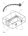
- FIG. 1 is a perspective view of a surgical cable and crimp device according to a preferred embodiment of the present invention, wherein the flexible cable and the crimp member are shown;
- FIG. 2 is a top view of the crimp member shown in FIG. 1 , prior to assembling with the flexible cable;
- FIG. 3 is a side view of the crimp member shown in FIG. 1 ;
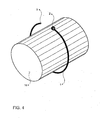
- FIG. 4 is a perspective view of a preferred embodiment of the flexible cable of the present invention, isolated from the crimp, looped around the bone;
- FIG. 5 is a perspective view of the crimp member shown in FIG. 1 , wherein the first beaded end of the cable is partially inserted into the crimp member;
- FIG. 6 is a perspective view of a cable and crimp device according to the preferred embodiment shown in FIG. 1 , wherein the flexible cable is already inserted into the crimp member and is ready to be tensed;
- FIG. 7 is a perspective view of another preferred embodiment of the crimp member of the present invention.
- FIG. 8 is a side view of the crimp member shown in FIG. 7 ;
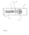
- FIG. 9 is a top view of the crimp member shown in FIG. 7 ;
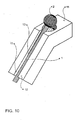
- FIG. 10 is a perspective view of the crimp member shown in FIG. 7 , wherein the flexible cable is partially inserted into the crimp member;
- FIG. 11 is a perspective view of the crimp member of FIG. 7 , wherein the flexible cable is completely inserted into the crimp and is ready to be tensed;
- FIG. 12 is a perspective view of a preferred embodiment of the flexible cable of the present invention, isolated from the crimp member, looped around the bone;
- FIG. 13 is a perspective view of the cable and crimp device according to the preferred embodiment of the present invention shown in FIGS. 7 and 12 , wherein the flexible cable is already looped around the bone and partially inserted into the crimp member;
- FIG. 14 is a perspective view of the cable and crimp device according to the preferred embodiment of the present invention shown in FIGS. 7 and 12 , wherein the flexible cable is already inserted into the crimp and is ready to be tensed.
- FIGS. 1 6 a method for securing surgical cable around a bone using a preferred embodiment of the present invention will be explained with reference to FIGS. 1 6 .
- FIG. 1 shows a preferred embodiment of the cable and crimp assembly of the present invention, disassembled.
- the flexible cable 1 has two ends - a first beaded end 2, and a second end 3.
- the crimp member 4 has a first hole 6 and a second hole 5.
- the second hole 5 is a simple through hole sized to accept the flexible cable 1.
- the first hole 6 is a complex two arms slotted hole. In the distal part of the hole 6, the slot 7 is sized to accommodate the cable, but not allow the enlargement (bead) 2 existing at the first end of the flexible cable 1 to pass through.
- the cavity 8 is located at the proximal arm of the hole, and is sized to accept the beaded first end of the cable 2.
- FIGS. 4-6 A preferred surgical procedure is described herein with reference to FIGS. 4-6 .
- the preferred surgical technique starts with the insertion of the flexible cable 1, isolated from the crimp member 4, around the bone to be cerclaged 16, as shown in FIG. 4
- the first beaded end 2 of the flexible cable 1 is inserted into the cavity 8 of the crimp member 4 as shown in FIG. 5 .
- the flexible cable 1 is then pulled in position emerging from the crimp 4 at the distal part of the first hole 6 of the crimp 4.
- the second end 3 of the flexible cable 1 is passed through the second hole 5, as shown in FIG. 6 .
- the cable and crimp device are then ready to be tensed.
- FIGS. 7-14 Another preferred embodiment of the present invention is shown with reference to FIGS. 7-14 .
- the crimp member 9, shown in FIGS. 7-10 has a first arm 10 and a second arm 11.
- the first arm 10 has a slotted hole with a larger part 14 sized to accept the enlargement (bead) 2 existing at the first end of the flexible cable 1, and a smaller sized slotted hole 15 sized to accept the flexible cable 1.
- This hole has a slot as indicated at 13.
- the second arm 11 of the crimp member 9 has a simple through hole 12 sized to accept the flexible cable 1.
- FIGS. 7-10 A preferred surgical procedure employing the embodiment shown in FIGS. 7-10 is described hereinto with reference to FIGS. 11-14 .
- the preferred surgical technique starts with the insertion of the flexible cable 1 . isolated from the crimp member 9 around the bone to be cerclaged 16, as shown in FIG. 12
- the first beaded end 2 of the flexible cable 1 is inserted into the cavity 14 of the crimp 9 as shown in FIG. 13 .
- the flexible cable 1 is then pulled in position to the slot of the hole 13.
- the second end 3 of the flexible cable 1 is passed through the second hole 12 of the crimp member 9, as shown in FIG. 14 .
- the flexible cable 1 is then tensioned by the application thereto of a tensioning tool with the tool applied to the flexible cable 1 and to an abutment face of the crimp member 9.
Landscapes
- Health & Medical Sciences (AREA)
- Orthopedic Medicine & Surgery (AREA)
- Surgery (AREA)
- Life Sciences & Earth Sciences (AREA)
- Heart & Thoracic Surgery (AREA)
- Nuclear Medicine, Radiotherapy & Molecular Imaging (AREA)
- Engineering & Computer Science (AREA)
- Biomedical Technology (AREA)
- Neurology (AREA)
- Medical Informatics (AREA)
- Molecular Biology (AREA)
- Animal Behavior & Ethology (AREA)
- General Health & Medical Sciences (AREA)
- Public Health (AREA)
- Veterinary Medicine (AREA)
- Surgical Instruments (AREA)
Description
- The present invention relates to orthopedics, and, more particularly, to an apparatus for securing surgical cable around bone.
- The use of surgical cable and crimp assemblies to fix bone parts and to join them together until the bone heals is a well-known technique. Surgical procedures on and in the vicinity of a bone with closely neighboring nerves, arteries, muscle, ligaments, complicated anatomical structures, and delicate areas represent a difficult and time consuming task for the surgeon. Thus it is important for the cable and crimp device to be assembled accurately, minimizing stress, trauma, risk, and injury to a patient, and with little difficulty for a surgeon performing such procedures, in as rapid a timeframe as possible.
- Furthermore it is desirable to maintain the bulk of the cable, as well as the joint where the cable is affixed to itself, as compact as possible to minimize discomfort to the patient and damage to the surrounding tissue.
- The orthopedic procedure is as follows: the cable, isolated from the crimp member, is inserted to loop around the bone in a minimally invasive way. After the cable is looped around the bone, its beaded first end is inserted into the cavity of the first hole of the crimp member. The slot at the first hole of the crimp member allows the first end of the cable to slide in place until the bead locks in its final position. The second end of the cable is then inserted through the second hole of the crimp member. Then the cable is tensioned by application of a tensioning tool either directly to the cable or through a provisional crimp, to an abutment face of the crimp close to the second hole of the crimp member. Once the desired final tension is established, the crimp member is crimped into the cable, the tensioning tool is removed, and the free end of the cable at the abutment face of the crimp is cut off.
- Different surgical tools have heretofore been known. However, none of the tools adequately satisfies these aforementioned needs. Most of the prior art surgical tools require pulling from both cable ends, after the cable is looped around the bone, as those disclosed in United States Patent Nos.
5,649,927 and6,017,347 . These kinds of devices have the problem of requiring significant spreading of the incision and muscle trauma. As a result, they are not a good solution for work in restricted areas. - Other devices permit tensioning of the cable by application of a tensioning tool to one of the cable ends and to an abutment face of the crimp by using a surgical cable which is factory crimped to one of the holes of the crimp, as those disclosed in United States Patent Nos.
5,423,820 ,6,077,268 and6,387,099 . The same effect is achieved by instruments that use a wire with a beaded end, as that disclosed in one embodiment of United States Patent No.6,017,347 . The bead locks into the end of the crimp preventing the wire from sliding out of the crimp. Another fastening apparatus is diclosed in United States Patent No.5,653,711 . - The option of pulling the cable by application of a tensioning tool to only one of the cable ends and to an abutment face of the crimp provides marked improvement over pulling from both cable ends when working in a restricted area.
- The effectiveness of the surgical cable and crimp assemblies has proven itself, but an improved surgical crimp is needed. The prior art instruments fail to provide an adequate technique and lengthen the overall procedure significantly. Thus there exists the need for an improved surgical crimp: compact, strong and easy to assemble in a confined area that allows the insertion of the surgical cable to loop the bone isolated from the crimp member, and to connect one of the cable ends to the crimp after the cable is looped around the bone.
- For the foregoing deficiencies in the prior art, a new cable and crimp assembly is needed which permits insertion of a surgical cable and looping of the cable around a bone while the cable is isolated from the crimp member, and, only after the cable is looped around the bone, permits the connection of one of the cable ends to the crimp member.
- Accordingly, it is an object of the present invention to provide a simple and effective tool for securing surgical cable around bone without requiring a large incision for the tool to be assembled.
- Another object of the invention herein is to provide an instrument wherein the exposure or stripping of the musculature away from the bone is minimized.
- It is also an object of the present invention to provide a cable and crimp assembly which is compact, which is easy to assemble, which securely fastens the cable around the bone while maintaining the desired level of tension in the cable, and which has the highest possible resistance to tensile forces.
- Furthermore, it is an object of the present invention to provide a cable and crimp assembly that enables the cable to be inserted isolated from the crimp member, and the crimp member to be attached to the surgical cable only after the cable is looped around the bone.
- The present invention comprises two members: a flexible cable and a crimp member. The surgical cable has an enlargement (a bead) affixed to its first end. The crimp member has a first hole and a second hole. The first hole is slotted and has a proximal and a distal part. The proximal part of the first hole has a cavity sized to accept the beaded end of cable. The distal part of the first hole is sized to allow the flexible cable to pass through, while the larger beaded first end of the cable is stopped. The second hole is non-slotted and sized to accommodate the cable. Preferably, there is an abutment face on the crimp member located near the second hole.
- The present invention creates an easy and straightforward procedure for the surgeon. This makes the crimp and cable technique simple and fast, overcoming one of the most important obstacles of actual surgery, time shortening.
- By fulfilling the recently mentioned objects, the present invention is extremely helpful to the medical care area.
- Other objects, advantages and novel features of the present invention will become apparent from the following detailed description of the invention when considered in conjunction with the accompanying drawings.
- Preferred embodiments of the present invention are disclosed in the accompanying drawings, wherein similar reference characters denote similar elements throughout the several views, and wherein:
-
FIG. 1 is a perspective view of a surgical cable and crimp device according to a preferred embodiment of the present invention, wherein the flexible cable and the crimp member are shown; -
FIG. 2 is a top view of the crimp member shown inFIG. 1 , prior to assembling with the flexible cable; -
FIG. 3 is a side view of the crimp member shown inFIG. 1 ; -
FIG. 4 is a perspective view of a preferred embodiment of the flexible cable of the present invention, isolated from the crimp, looped around the bone; -
FIG. 5 is a perspective view of the crimp member shown inFIG. 1 , wherein the first beaded end of the cable is partially inserted into the crimp member; -
FIG. 6 is a perspective view of a cable and crimp device according to the preferred embodiment shown inFIG. 1 , wherein the flexible cable is already inserted into the crimp member and is ready to be tensed; -
FIG. 7 is a perspective view of another preferred embodiment of the crimp member of the present invention; -
FIG. 8 is a side view of the crimp member shown inFIG. 7 ; -
FIG. 9 is a top view of the crimp member shown inFIG. 7 ; -
FIG. 10 is a perspective view of the crimp member shown inFIG. 7 , wherein the flexible cable is partially inserted into the crimp member; -
FIG. 11 is a perspective view of the crimp member ofFIG. 7 , wherein the flexible cable is completely inserted into the crimp and is ready to be tensed; -
FIG. 12 is a perspective view of a preferred embodiment of the flexible cable of the present invention, isolated from the crimp member, looped around the bone; -
FIG. 13 is a perspective view of the cable and crimp device according to the preferred embodiment of the present invention shown inFIGS. 7 and12 , wherein the flexible cable is already looped around the bone and partially inserted into the crimp member; and -
FIG. 14 is a perspective view of the cable and crimp device according to the preferred embodiment of the present invention shown inFIGS. 7 and12 , wherein the flexible cable is already inserted into the crimp and is ready to be tensed. - Hereinafter, a method for securing surgical cable around a bone using a preferred embodiment of the present invention will be explained with reference to
FIGS. 1 6 . -
FIG. 1 shows a preferred embodiment of the cable and crimp assembly of the present invention, disassembled. Theflexible cable 1 has two ends - a firstbeaded end 2, and asecond end 3. Thecrimp member 4 has afirst hole 6 and asecond hole 5. Thesecond hole 5 is a simple through hole sized to accept theflexible cable 1. Thefirst hole 6 is a complex two arms slotted hole. In the distal part of thehole 6, theslot 7 is sized to accommodate the cable, but not allow the enlargement (bead) 2 existing at the first end of theflexible cable 1 to pass through. Thecavity 8 is located at the proximal arm of the hole, and is sized to accept the beaded first end of thecable 2. - The different sizes of the two arms of the slotted
hole 6 are clearly seen inFIG. 3 . - A preferred surgical procedure is described herein with reference to
FIGS. 4-6 . - The preferred surgical technique starts with the insertion of the
flexible cable 1, isolated from thecrimp member 4, around the bone to be cerclaged 16, as shown inFIG. 4 - After the
flexible cable 1 is looped around the bone to be cerclaged 16, the firstbeaded end 2 of theflexible cable 1, is inserted into thecavity 8 of thecrimp member 4 as shown inFIG. 5 . Theflexible cable 1 is then pulled in position emerging from thecrimp 4 at the distal part of thefirst hole 6 of thecrimp 4. Then thesecond end 3 of theflexible cable 1 is passed through thesecond hole 5, as shown inFIG. 6 . The cable and crimp device are then ready to be tensed. - Another preferred embodiment of the present invention is shown with reference to
FIGS. 7-14 . - The
crimp member 9, shown inFIGS. 7-10 , has afirst arm 10 and asecond arm 11. Thefirst arm 10 has a slotted hole with alarger part 14 sized to accept the enlargement (bead) 2 existing at the first end of theflexible cable 1, and a smaller sized slottedhole 15 sized to accept theflexible cable 1. This hole has a slot as indicated at 13. Thesecond arm 11 of thecrimp member 9 has a simple throughhole 12 sized to accept theflexible cable 1. - A preferred surgical procedure employing the embodiment shown in
FIGS. 7-10 is described hereinto with reference toFIGS. 11-14 . - The preferred surgical technique starts with the insertion of the
flexible cable 1 . isolated from thecrimp member 9 around the bone to be cerclaged 16, as shown inFIG. 12 - After the
flexible cable 1 is looped around the bone to be cerclaged 16, the firstbeaded end 2 of theflexible cable 1, is inserted into thecavity 14 of thecrimp 9 as shown inFIG. 13 . Theflexible cable 1 is then pulled in position to the slot of thehole 13. Then, thesecond end 3 of theflexible cable 1 is passed through thesecond hole 12 of thecrimp member 9, as shown inFIG. 14 . Theflexible cable 1 is then tensioned by the application thereto of a tensioning tool with the tool applied to theflexible cable 1 and to an abutment face of thecrimp member 9. - While I have illustrated and described preferred embodiments of the invention, it will be understood that those skilled in the art will thereby be enabled to devise variations and modifications without departing from the scope of this invention, as defined in the appended claims.
Claims (10)
- A fastening apparatus for fixing bone elements comprising:a flexible cable (1) having a first end (2), a second end (3), and a width, the first end including an enlargement greater than the width of the cable;a crimp member (4) includinga first hole (6) having a length, a proximal portion, a distal portion, and a slot (7) running along the length of the hole, the proximal portion of the first hole including a cavity (8) configured and dimensioned to accept the enlargement at the first end of the cable, the slot configured and dimensioned to permit the width of the cable to pass through the slot, and the distal portion of the first hole configured and dimensioned to permit the width of the cable to pass through the distal portion of the first hole and prevent the enlargement from passing through the distal portion of the first hole, anda second hole (5) having a length, the second hole configured and dimensioned to permit insertion of the second end of the cable through the second hole.
- The apparatus of claim 1, wherein the crimp member is configured for attachment to the flexible cable after the cable has been looped around a bone.
- The apparatus of claim 2, wherein the crimp member is attached to the cable by insertion of the first end of the cable into the first hole of the crimp member and insertion of the second end of the cable through the second hole of the crimp member to form a loop of adjustable diameter.
- The apparatus of any of the preceding claims, wherein the first and second holes of the crimp member are parallel straight holes.
- The apparatus of any of the preceding claims, wherein the first and second holes of the crimp member are coplanar.
- The apparatus of any of the preceding claims, wherein the proximal portion of the first hole defines a first axis and the distal portion of the second hole defines a second axis, and the first and second axes are not collinear.
- The apparatus of any of the preceding claims, wherein the proximal portion of the first hole is coplanar with the second hole.
- The apparatus of any of the preceding claims, wherein the distal portion of the first hole is substantially parallel to the second hole.
- The apparatus of any of the preceding claims, wherein the first and second holes of the crimp member are not parallel.
- The apparatus of any of the preceding claims, wherein the enlargement (2) is an enlarged first end of the flexible cable.
Applications Claiming Priority (2)
| Application Number | Priority Date | Filing Date | Title |
|---|---|---|---|
| US11/248,418 US7833227B2 (en) | 2005-10-13 | 2005-10-13 | Cable and crimp for bone surgery |
| PCT/US2006/040147 WO2007047467A1 (en) | 2005-10-13 | 2006-10-13 | Cable and crimp for bone surgery |
Publications (2)
| Publication Number | Publication Date |
|---|---|
| EP1933740A1 EP1933740A1 (en) | 2008-06-25 |
| EP1933740B1 true EP1933740B1 (en) | 2013-08-14 |
Family
ID=37781602
Family Applications (1)
| Application Number | Title | Priority Date | Filing Date |
|---|---|---|---|
| EP06816900.2A Not-in-force EP1933740B1 (en) | 2005-10-13 | 2006-10-13 | Cable and crimp for bone surgery |
Country Status (10)
| Country | Link |
|---|---|
| US (2) | US7833227B2 (en) |
| EP (1) | EP1933740B1 (en) |
| JP (1) | JP5028421B2 (en) |
| KR (1) | KR101299145B1 (en) |
| CN (1) | CN101282691B (en) |
| AU (1) | AU2006304276A1 (en) |
| BR (1) | BRPI0617357B8 (en) |
| CA (1) | CA2625742C (en) |
| WO (1) | WO2007047467A1 (en) |
| ZA (1) | ZA200803229B (en) |
Cited By (1)
| Publication number | Priority date | Publication date | Assignee | Title |
|---|---|---|---|---|
| DE102018002705B4 (en) | 2018-03-28 | 2022-01-05 | Merete Gmbh | System for the reduction of fragments of the supporting apparatus by means of a rope osteosynthesis |
Families Citing this family (20)
| Publication number | Priority date | Publication date | Assignee | Title |
|---|---|---|---|---|
| EP2124787B1 (en) * | 2007-02-28 | 2016-02-24 | Synthes GmbH | Grooved crimp with a set screw |
| US8882816B2 (en) | 2007-08-02 | 2014-11-11 | Proactive Orthopedics, Llc | Fixation and alignment device and method used in orthopaedic surgery |
| US8142434B2 (en) | 2007-10-17 | 2012-03-27 | Stryker Trauma Gmbh | Cam-locking of cable for fracture plate |
| WO2009064628A2 (en) * | 2007-11-13 | 2009-05-22 | Synthes (U.S.A) | Minimally invasive cerclage system |
| BRPI0913999A2 (en) | 2008-07-25 | 2015-10-27 | Synthes Gmbh | minimally invasive attachment and implant system |
| CN101884563B (en) * | 2010-07-09 | 2012-03-21 | 张英泽 | Flexible fixing device for orthopedics |
| US9101399B2 (en) | 2011-12-29 | 2015-08-11 | Proactive Orthopedics, Llc | Anchoring systems and methods for surgery |
| CA2907345A1 (en) * | 2013-03-15 | 2014-09-18 | Matthew Songer | Cable fixation device |
| US10258400B2 (en) | 2013-03-15 | 2019-04-16 | J. M. Longyear Manufacturing Llc | Cable fixation device, instruments, and methods |
| US9173510B1 (en) * | 2014-05-16 | 2015-11-03 | Robert W. Miller | Frame hanging wire post with locking connector |
| JP6483590B2 (en) * | 2015-11-06 | 2019-03-13 | 株式会社ニフコ | Stringing device |
| EP3184064B1 (en) * | 2015-12-23 | 2019-05-01 | Stryker European Holdings I, LLC | Bone plate with guiding channels |
| US11123176B2 (en) | 2016-03-13 | 2021-09-21 | Pontis Orthopaedics Llc | Apparatus and method for repair of disruptions between bones |
| US10820935B2 (en) | 2017-02-03 | 2020-11-03 | Stryker European Holdings I, Llc | Tensioning cable locking device |
| WO2018167573A1 (en) * | 2017-03-13 | 2018-09-20 | Xpand Inc. | Shoe lace lock and system and method for lacing shoes |
| WO2019055723A1 (en) * | 2017-09-15 | 2019-03-21 | Dsm Ip Assets, B.V. | Medical fixation device for polymer cables |
| CN109998662B (en) * | 2019-04-25 | 2022-02-01 | 陇西县中医医院 | Internal fixing device for fracture and lock catch thereof |
| US11918087B2 (en) * | 2019-09-18 | 2024-03-05 | LT Brands, Inc. | Cord lock apparatus and belt with same |
| FR3100968B1 (en) * | 2019-09-24 | 2023-04-14 | Cousin Biotech | Strapping device, in particular for the consolidation of a peri-prosthetic fracture |
| GB2622802A (en) * | 2022-09-28 | 2024-04-03 | Cmr Surgical Ltd | Securing a driving element in an instrument interface of a robotic surgical instrument |
Family Cites Families (22)
| Publication number | Priority date | Publication date | Assignee | Title |
|---|---|---|---|---|
| US131593A (en) * | 1872-09-24 | Improvement in bag-ties | ||
| US1753901A (en) * | 1929-01-14 | 1930-04-08 | Edwin James Brand | Clothesline fastener |
| US2503151A (en) * | 1947-07-05 | 1950-04-04 | Electric Steel Foundry | Hook for forming slip hitches in cables or the like |
| US2518276A (en) * | 1947-09-06 | 1950-08-08 | Franklin M Brawand | Butt hook |
| US3239900A (en) * | 1963-02-19 | 1966-03-15 | Timberland Ellicott Ltd | Choker hook |
| US3654668A (en) * | 1970-05-15 | 1972-04-11 | Arthur I Appleton | Wrapping device |
| US4540209A (en) * | 1983-08-15 | 1985-09-10 | Esco Corporation | Rigging method and hook therefor |
| JPH0540324Y2 (en) * | 1987-03-17 | 1993-10-13 | ||
| CA1323176C (en) * | 1988-11-25 | 1993-10-19 | Carl H. Baker | Cable retaining apparatus |
| US5836061A (en) * | 1997-07-12 | 1998-11-17 | Honda Giken Kogyo Kabushiki Kaisha | Cable end anchoring nipple and methods of constructing and utilizing same |
| US6017347A (en) | 1995-06-01 | 2000-01-25 | Acumed, Inc. | Wire clamp assembly |
| US5423820A (en) | 1993-07-20 | 1995-06-13 | Danek Medical, Inc. | Surgical cable and crimp |
| US5339498A (en) * | 1993-09-28 | 1994-08-23 | Parsons Llewellyn B | Adjustable tyer |
| US5415658A (en) | 1993-12-14 | 1995-05-16 | Pioneer Laboratories, Inc. | Surgical cable loop connector |
| US5569253A (en) | 1994-03-29 | 1996-10-29 | Danek Medical, Inc. | Variable-angle surgical cable crimp assembly and method |
| US5653711A (en) | 1994-08-08 | 1997-08-05 | Kijuro Hayano | Wire fastening tool |
| US5649927A (en) | 1995-09-27 | 1997-07-22 | Pioneer Laboratories, Inc. | Cable crimp system |
| US6068648A (en) | 1998-01-26 | 2000-05-30 | Orthodyne, Inc. | Tissue anchoring system and method |
| US6387099B1 (en) | 2000-03-24 | 2002-05-14 | Synthes (Usa) | Surgical cable crimp |
| US20060106391A1 (en) * | 2004-11-12 | 2006-05-18 | Huebner Randall J | Wire systems for fixing bones |
| MXPA04009877A (en) * | 2002-04-09 | 2004-12-07 | Synthes Ag | Device for guiding a cerclage wire. |
| US7250054B2 (en) | 2002-08-28 | 2007-07-31 | Smith & Nephew, Inc. | Systems, methods, and apparatuses for clamping and reclamping an orthopedic surgical cable |
-
2005
- 2005-10-13 US US11/248,418 patent/US7833227B2/en active Active
-
2006
- 2006-10-13 WO PCT/US2006/040147 patent/WO2007047467A1/en active Application Filing
- 2006-10-13 JP JP2008535723A patent/JP5028421B2/en not_active Expired - Fee Related
- 2006-10-13 AU AU2006304276A patent/AU2006304276A1/en not_active Abandoned
- 2006-10-13 EP EP06816900.2A patent/EP1933740B1/en not_active Not-in-force
- 2006-10-13 BR BRPI0617357A patent/BRPI0617357B8/en not_active IP Right Cessation
- 2006-10-13 CA CA2625742A patent/CA2625742C/en not_active Expired - Fee Related
- 2006-10-13 ZA ZA200803229A patent/ZA200803229B/en unknown
- 2006-10-13 KR KR1020087011072A patent/KR101299145B1/en not_active IP Right Cessation
- 2006-10-13 CN CN200680037782XA patent/CN101282691B/en not_active Expired - Fee Related
-
2010
- 2010-10-19 US US12/907,541 patent/US8608742B2/en active Active
Cited By (1)
| Publication number | Priority date | Publication date | Assignee | Title |
|---|---|---|---|---|
| DE102018002705B4 (en) | 2018-03-28 | 2022-01-05 | Merete Gmbh | System for the reduction of fragments of the supporting apparatus by means of a rope osteosynthesis |
Also Published As
| Publication number | Publication date |
|---|---|
| AU2006304276A1 (en) | 2007-04-26 |
| US20110034928A1 (en) | 2011-02-10 |
| KR20080069989A (en) | 2008-07-29 |
| CN101282691A (en) | 2008-10-08 |
| US7833227B2 (en) | 2010-11-16 |
| BRPI0617357B8 (en) | 2021-06-22 |
| JP5028421B2 (en) | 2012-09-19 |
| JP2009511203A (en) | 2009-03-19 |
| CN101282691B (en) | 2011-09-07 |
| KR101299145B1 (en) | 2013-08-21 |
| CA2625742C (en) | 2014-02-11 |
| EP1933740A1 (en) | 2008-06-25 |
| WO2007047467A1 (en) | 2007-04-26 |
| CA2625742A1 (en) | 2007-04-26 |
| BRPI0617357A2 (en) | 2011-07-26 |
| BRPI0617357B1 (en) | 2018-02-14 |
| US20070100345A1 (en) | 2007-05-03 |
| ZA200803229B (en) | 2009-07-29 |
| US8608742B2 (en) | 2013-12-17 |
Similar Documents
| Publication | Publication Date | Title |
|---|---|---|
| EP1933740B1 (en) | Cable and crimp for bone surgery | |
| US5474554A (en) | Method for fixation of avulsion fracture | |
| US9326807B2 (en) | Peri-prosthetic fixation implant and method | |
| US8277451B2 (en) | Two members cerclage tool | |
| US9795431B2 (en) | Long-nosed crimp pliers for use in orthopedics | |
| US10512497B2 (en) | Grooved crimp with a set screw | |
| WO2016154550A1 (en) | Joint repair system | |
| JP2022174290A (en) | Intra joint stabilization construct | |
| WO2018118931A1 (en) | Syndesmosis construct | |
| CA2863899C (en) | Suture distal locking for intramedullary nail | |
| CN214434345U (en) | Soft tissue repair device |
Legal Events
| Date | Code | Title | Description |
|---|---|---|---|
| PUAI | Public reference made under article 153(3) epc to a published international application that has entered the european phase |
Free format text: ORIGINAL CODE: 0009012 |
|
| 17P | Request for examination filed |
Effective date: 20080411 |
|
| AK | Designated contracting states |
Kind code of ref document: A1 Designated state(s): AT BE BG CH CY CZ DE DK EE ES FI FR GB GR HU IE IS IT LI LT LU LV MC NL PL PT RO SE SI SK TR |
|
| DAX | Request for extension of the european patent (deleted) | ||
| GRAP | Despatch of communication of intention to grant a patent |
Free format text: ORIGINAL CODE: EPIDOSNIGR1 |
|
| INTG | Intention to grant announced |
Effective date: 20130423 |
|
| GRAS | Grant fee paid |
Free format text: ORIGINAL CODE: EPIDOSNIGR3 |
|
| GRAA | (expected) grant |
Free format text: ORIGINAL CODE: 0009210 |
|
| AK | Designated contracting states |
Kind code of ref document: B1 Designated state(s): AT BE BG CH CY CZ DE DK EE ES FI FR GB GR HU IE IS IT LI LT LU LV MC NL PL PT RO SE SI SK TR |
|
| REG | Reference to a national code |
Ref country code: GB Ref legal event code: FG4D |
|
| REG | Reference to a national code |
Ref country code: CH Ref legal event code: EP Ref country code: AT Ref legal event code: REF Ref document number: 626309 Country of ref document: AT Kind code of ref document: T Effective date: 20130815 |
|
| REG | Reference to a national code |
Ref country code: IE Ref legal event code: FG4D |
|
| REG | Reference to a national code |
Ref country code: CH Ref legal event code: NV Representative=s name: DR. LUSUARDI AG, CH |
|
| REG | Reference to a national code |
Ref country code: DE Ref legal event code: R096 Ref document number: 602006037880 Country of ref document: DE Effective date: 20131010 |
|
| REG | Reference to a national code |
Ref country code: AT Ref legal event code: MK05 Ref document number: 626309 Country of ref document: AT Kind code of ref document: T Effective date: 20130814 Ref country code: NL Ref legal event code: VDEP Effective date: 20130814 |
|
| REG | Reference to a national code |
Ref country code: LT Ref legal event code: MG4D |
|
| PG25 | Lapsed in a contracting state [announced via postgrant information from national office to epo] |
Ref country code: AT Free format text: LAPSE BECAUSE OF FAILURE TO SUBMIT A TRANSLATION OF THE DESCRIPTION OR TO PAY THE FEE WITHIN THE PRESCRIBED TIME-LIMIT Effective date: 20130814 Ref country code: SE Free format text: LAPSE BECAUSE OF FAILURE TO SUBMIT A TRANSLATION OF THE DESCRIPTION OR TO PAY THE FEE WITHIN THE PRESCRIBED TIME-LIMIT Effective date: 20130814 Ref country code: PT Free format text: LAPSE BECAUSE OF FAILURE TO SUBMIT A TRANSLATION OF THE DESCRIPTION OR TO PAY THE FEE WITHIN THE PRESCRIBED TIME-LIMIT Effective date: 20131216 Ref country code: IS Free format text: LAPSE BECAUSE OF FAILURE TO SUBMIT A TRANSLATION OF THE DESCRIPTION OR TO PAY THE FEE WITHIN THE PRESCRIBED TIME-LIMIT Effective date: 20131214 Ref country code: LT Free format text: LAPSE BECAUSE OF FAILURE TO SUBMIT A TRANSLATION OF THE DESCRIPTION OR TO PAY THE FEE WITHIN THE PRESCRIBED TIME-LIMIT Effective date: 20130814 Ref country code: CY Free format text: LAPSE BECAUSE OF FAILURE TO SUBMIT A TRANSLATION OF THE DESCRIPTION OR TO PAY THE FEE WITHIN THE PRESCRIBED TIME-LIMIT Effective date: 20130724 |
|
| PG25 | Lapsed in a contracting state [announced via postgrant information from national office to epo] |
Ref country code: FI Free format text: LAPSE BECAUSE OF FAILURE TO SUBMIT A TRANSLATION OF THE DESCRIPTION OR TO PAY THE FEE WITHIN THE PRESCRIBED TIME-LIMIT Effective date: 20130814 Ref country code: LV Free format text: LAPSE BECAUSE OF FAILURE TO SUBMIT A TRANSLATION OF THE DESCRIPTION OR TO PAY THE FEE WITHIN THE PRESCRIBED TIME-LIMIT Effective date: 20130814 Ref country code: BE Free format text: LAPSE BECAUSE OF FAILURE TO SUBMIT A TRANSLATION OF THE DESCRIPTION OR TO PAY THE FEE WITHIN THE PRESCRIBED TIME-LIMIT Effective date: 20130814 Ref country code: GR Free format text: LAPSE BECAUSE OF FAILURE TO SUBMIT A TRANSLATION OF THE DESCRIPTION OR TO PAY THE FEE WITHIN THE PRESCRIBED TIME-LIMIT Effective date: 20131115 Ref country code: SI Free format text: LAPSE BECAUSE OF FAILURE TO SUBMIT A TRANSLATION OF THE DESCRIPTION OR TO PAY THE FEE WITHIN THE PRESCRIBED TIME-LIMIT Effective date: 20130814 Ref country code: PL Free format text: LAPSE BECAUSE OF FAILURE TO SUBMIT A TRANSLATION OF THE DESCRIPTION OR TO PAY THE FEE WITHIN THE PRESCRIBED TIME-LIMIT Effective date: 20130814 |
|
| PG25 | Lapsed in a contracting state [announced via postgrant information from national office to epo] |
Ref country code: CY Free format text: LAPSE BECAUSE OF FAILURE TO SUBMIT A TRANSLATION OF THE DESCRIPTION OR TO PAY THE FEE WITHIN THE PRESCRIBED TIME-LIMIT Effective date: 20130814 |
|
| PG25 | Lapsed in a contracting state [announced via postgrant information from national office to epo] |
Ref country code: EE Free format text: LAPSE BECAUSE OF FAILURE TO SUBMIT A TRANSLATION OF THE DESCRIPTION OR TO PAY THE FEE WITHIN THE PRESCRIBED TIME-LIMIT Effective date: 20130814 Ref country code: NL Free format text: LAPSE BECAUSE OF FAILURE TO SUBMIT A TRANSLATION OF THE DESCRIPTION OR TO PAY THE FEE WITHIN THE PRESCRIBED TIME-LIMIT Effective date: 20130814 Ref country code: CZ Free format text: LAPSE BECAUSE OF FAILURE TO SUBMIT A TRANSLATION OF THE DESCRIPTION OR TO PAY THE FEE WITHIN THE PRESCRIBED TIME-LIMIT Effective date: 20130814 Ref country code: RO Free format text: LAPSE BECAUSE OF FAILURE TO SUBMIT A TRANSLATION OF THE DESCRIPTION OR TO PAY THE FEE WITHIN THE PRESCRIBED TIME-LIMIT Effective date: 20130814 Ref country code: DK Free format text: LAPSE BECAUSE OF FAILURE TO SUBMIT A TRANSLATION OF THE DESCRIPTION OR TO PAY THE FEE WITHIN THE PRESCRIBED TIME-LIMIT Effective date: 20130814 Ref country code: SK Free format text: LAPSE BECAUSE OF FAILURE TO SUBMIT A TRANSLATION OF THE DESCRIPTION OR TO PAY THE FEE WITHIN THE PRESCRIBED TIME-LIMIT Effective date: 20130814 |
|
| PG25 | Lapsed in a contracting state [announced via postgrant information from national office to epo] |
Ref country code: MC Free format text: LAPSE BECAUSE OF FAILURE TO SUBMIT A TRANSLATION OF THE DESCRIPTION OR TO PAY THE FEE WITHIN THE PRESCRIBED TIME-LIMIT Effective date: 20130814 Ref country code: ES Free format text: LAPSE BECAUSE OF FAILURE TO SUBMIT A TRANSLATION OF THE DESCRIPTION OR TO PAY THE FEE WITHIN THE PRESCRIBED TIME-LIMIT Effective date: 20130814 |
|
| PLBE | No opposition filed within time limit |
Free format text: ORIGINAL CODE: 0009261 |
|
| STAA | Information on the status of an ep patent application or granted ep patent |
Free format text: STATUS: NO OPPOSITION FILED WITHIN TIME LIMIT |
|
| 26N | No opposition filed |
Effective date: 20140515 |
|
| REG | Reference to a national code |
Ref country code: IE Ref legal event code: MM4A |
|
| REG | Reference to a national code |
Ref country code: DE Ref legal event code: R097 Ref document number: 602006037880 Country of ref document: DE Effective date: 20140515 |
|
| PG25 | Lapsed in a contracting state [announced via postgrant information from national office to epo] |
Ref country code: IE Free format text: LAPSE BECAUSE OF NON-PAYMENT OF DUE FEES Effective date: 20131013 |
|
| PG25 | Lapsed in a contracting state [announced via postgrant information from national office to epo] |
Ref country code: TR Free format text: LAPSE BECAUSE OF FAILURE TO SUBMIT A TRANSLATION OF THE DESCRIPTION OR TO PAY THE FEE WITHIN THE PRESCRIBED TIME-LIMIT Effective date: 20130814 |
|
| PG25 | Lapsed in a contracting state [announced via postgrant information from national office to epo] |
Ref country code: HU Free format text: LAPSE BECAUSE OF FAILURE TO SUBMIT A TRANSLATION OF THE DESCRIPTION OR TO PAY THE FEE WITHIN THE PRESCRIBED TIME-LIMIT; INVALID AB INITIO Effective date: 20061013 Ref country code: BG Free format text: LAPSE BECAUSE OF FAILURE TO SUBMIT A TRANSLATION OF THE DESCRIPTION OR TO PAY THE FEE WITHIN THE PRESCRIBED TIME-LIMIT Effective date: 20130814 Ref country code: LU Free format text: LAPSE BECAUSE OF NON-PAYMENT OF DUE FEES Effective date: 20131013 |
|
| REG | Reference to a national code |
Ref country code: FR Ref legal event code: PLFP Year of fee payment: 11 |
|
| REG | Reference to a national code |
Ref country code: FR Ref legal event code: PLFP Year of fee payment: 12 |
|
| REG | Reference to a national code |
Ref country code: FR Ref legal event code: PLFP Year of fee payment: 13 |
|
| PGFP | Annual fee paid to national office [announced via postgrant information from national office to epo] |
Ref country code: FR Payment date: 20190913 Year of fee payment: 14 |
|
| PGFP | Annual fee paid to national office [announced via postgrant information from national office to epo] |
Ref country code: DE Payment date: 20191001 Year of fee payment: 14 |
|
| PGFP | Annual fee paid to national office [announced via postgrant information from national office to epo] |
Ref country code: IT Payment date: 20191009 Year of fee payment: 14 |
|
| PGFP | Annual fee paid to national office [announced via postgrant information from national office to epo] |
Ref country code: CH Payment date: 20191015 Year of fee payment: 14 |
|
| PGFP | Annual fee paid to national office [announced via postgrant information from national office to epo] |
Ref country code: GB Payment date: 20191010 Year of fee payment: 14 |
|
| REG | Reference to a national code |
Ref country code: DE Ref legal event code: R119 Ref document number: 602006037880 Country of ref document: DE |
|
| REG | Reference to a national code |
Ref country code: CH Ref legal event code: PL |
|
| GBPC | Gb: european patent ceased through non-payment of renewal fee |
Effective date: 20201013 |
|
| PG25 | Lapsed in a contracting state [announced via postgrant information from national office to epo] |
Ref country code: DE Free format text: LAPSE BECAUSE OF NON-PAYMENT OF DUE FEES Effective date: 20210501 Ref country code: FR Free format text: LAPSE BECAUSE OF NON-PAYMENT OF DUE FEES Effective date: 20201031 |
|
| PG25 | Lapsed in a contracting state [announced via postgrant information from national office to epo] |
Ref country code: CH Free format text: LAPSE BECAUSE OF NON-PAYMENT OF DUE FEES Effective date: 20201031 Ref country code: LI Free format text: LAPSE BECAUSE OF NON-PAYMENT OF DUE FEES Effective date: 20201031 Ref country code: GB Free format text: LAPSE BECAUSE OF NON-PAYMENT OF DUE FEES Effective date: 20201013 |
|
| PG25 | Lapsed in a contracting state [announced via postgrant information from national office to epo] |
Ref country code: IT Free format text: LAPSE BECAUSE OF NON-PAYMENT OF DUE FEES Effective date: 20201013 |