EP1933729B1 - Vorrichtung zur wärmebehandlung von beweglichem biologischem gewebe und relevantes positionierung verfahren - Google Patents
Vorrichtung zur wärmebehandlung von beweglichem biologischem gewebe und relevantes positionierung verfahren Download PDFInfo
- Publication number
- EP1933729B1 EP1933729B1 EP06778412A EP06778412A EP1933729B1 EP 1933729 B1 EP1933729 B1 EP 1933729B1 EP 06778412 A EP06778412 A EP 06778412A EP 06778412 A EP06778412 A EP 06778412A EP 1933729 B1 EP1933729 B1 EP 1933729B1
- Authority
- EP
- European Patent Office
- Prior art keywords
- target area
- movement
- estimated
- positioning
- target region
- Prior art date
- Legal status (The legal status is an assumption and is not a legal conclusion. Google has not performed a legal analysis and makes no representation as to the accuracy of the status listed.)
- Ceased
Links
- 238000000034 method Methods 0.000 title claims description 52
- 230000033001 locomotion Effects 0.000 claims abstract description 190
- 238000011282 treatment Methods 0.000 claims abstract description 127
- 238000005259 measurement Methods 0.000 claims abstract description 49
- 238000006073 displacement reaction Methods 0.000 claims description 53
- 230000002123 temporal effect Effects 0.000 claims description 50
- 238000009826 distribution Methods 0.000 claims description 38
- 238000010438 heat treatment Methods 0.000 claims description 35
- 238000004364 calculation method Methods 0.000 claims description 32
- 238000012545 processing Methods 0.000 claims description 30
- 238000003384 imaging method Methods 0.000 claims description 29
- 230000000737 periodic effect Effects 0.000 claims description 25
- 239000013598 vector Substances 0.000 claims description 16
- 238000004422 calculation algorithm Methods 0.000 claims description 15
- 230000005855 radiation Effects 0.000 claims description 13
- 238000012544 monitoring process Methods 0.000 claims description 9
- 230000033228 biological regulation Effects 0.000 claims description 7
- 230000001105 regulatory effect Effects 0.000 claims description 6
- 230000001276 controlling effect Effects 0.000 claims 1
- 230000001419 dependent effect Effects 0.000 claims 1
- 230000003466 anti-cipated effect Effects 0.000 abstract description 37
- 238000007669 thermal treatment Methods 0.000 abstract description 3
- 230000002977 hyperthermial effect Effects 0.000 abstract 1
- 238000012937 correction Methods 0.000 description 68
- 210000001519 tissue Anatomy 0.000 description 57
- 238000002595 magnetic resonance imaging Methods 0.000 description 37
- 238000011156 evaluation Methods 0.000 description 24
- 238000004861 thermometry Methods 0.000 description 23
- 210000003205 muscle Anatomy 0.000 description 16
- 238000002474 experimental method Methods 0.000 description 9
- 239000004744 fabric Substances 0.000 description 9
- 230000017074 necrotic cell death Effects 0.000 description 9
- 238000002604 ultrasonography Methods 0.000 description 8
- 239000011159 matrix material Substances 0.000 description 7
- 238000013459 approach Methods 0.000 description 6
- 230000000241 respiratory effect Effects 0.000 description 6
- 230000005540 biological transmission Effects 0.000 description 5
- 230000008569 process Effects 0.000 description 5
- 238000005070 sampling Methods 0.000 description 4
- 238000013519 translation Methods 0.000 description 4
- 238000009792 diffusion process Methods 0.000 description 3
- 230000005291 magnetic effect Effects 0.000 description 3
- 210000000056 organ Anatomy 0.000 description 3
- 238000012546 transfer Methods 0.000 description 3
- 206010020843 Hyperthermia Diseases 0.000 description 2
- 238000010521 absorption reaction Methods 0.000 description 2
- 238000004458 analytical method Methods 0.000 description 2
- 230000036031 hyperthermia Effects 0.000 description 2
- 238000009217 hyperthermia therapy Methods 0.000 description 2
- 230000000670 limiting effect Effects 0.000 description 2
- 230000010363 phase shift Effects 0.000 description 2
- 238000003672 processing method Methods 0.000 description 2
- 230000004044 response Effects 0.000 description 2
- 238000013456 study Methods 0.000 description 2
- 230000009466 transformation Effects 0.000 description 2
- PXFBZOLANLWPMH-UHFFFAOYSA-N 16-Epiaffinine Natural products C1C(C2=CC=CC=C2N2)=C2C(=O)CC2C(=CC)CN(C)C1C2CO PXFBZOLANLWPMH-UHFFFAOYSA-N 0.000 description 1
- 241000282414 Homo sapiens Species 0.000 description 1
- 210000001015 abdomen Anatomy 0.000 description 1
- 238000009825 accumulation Methods 0.000 description 1
- 230000015572 biosynthetic process Effects 0.000 description 1
- 238000009529 body temperature measurement Methods 0.000 description 1
- 230000000747 cardiac effect Effects 0.000 description 1
- 230000008859 change Effects 0.000 description 1
- 238000006243 chemical reaction Methods 0.000 description 1
- 238000010276 construction Methods 0.000 description 1
- 230000008602 contraction Effects 0.000 description 1
- 238000001816 cooling Methods 0.000 description 1
- 238000001514 detection method Methods 0.000 description 1
- 230000000694 effects Effects 0.000 description 1
- 238000005516 engineering process Methods 0.000 description 1
- 230000014509 gene expression Effects 0.000 description 1
- 230000001976 improved effect Effects 0.000 description 1
- 230000006698 induction Effects 0.000 description 1
- 230000010365 information processing Effects 0.000 description 1
- 230000001678 irradiating effect Effects 0.000 description 1
- 210000003734 kidney Anatomy 0.000 description 1
- 210000004185 liver Anatomy 0.000 description 1
- 230000005415 magnetization Effects 0.000 description 1
- 238000013507 mapping Methods 0.000 description 1
- 238000012986 modification Methods 0.000 description 1
- 239000003607 modifier Substances 0.000 description 1
- 239000013307 optical fiber Substances 0.000 description 1
- 238000005457 optimization Methods 0.000 description 1
- 230000036961 partial effect Effects 0.000 description 1
- 238000007781 pre-processing Methods 0.000 description 1
- 230000002829 reductive effect Effects 0.000 description 1
- 230000029058 respiratory gaseous exchange Effects 0.000 description 1
- 230000003068 static effect Effects 0.000 description 1
- 238000012360 testing method Methods 0.000 description 1
- 238000003325 tomography Methods 0.000 description 1
- 238000000844 transformation Methods 0.000 description 1
- XLYOFNOQVPJJNP-UHFFFAOYSA-N water Substances O XLYOFNOQVPJJNP-UHFFFAOYSA-N 0.000 description 1
- 229910001868 water Inorganic materials 0.000 description 1
Images





Classifications
-
- A—HUMAN NECESSITIES
- A61—MEDICAL OR VETERINARY SCIENCE; HYGIENE
- A61N—ELECTROTHERAPY; MAGNETOTHERAPY; RADIATION THERAPY; ULTRASOUND THERAPY
- A61N7/00—Ultrasound therapy
- A61N7/02—Localised ultrasound hyperthermia
-
- A—HUMAN NECESSITIES
- A61—MEDICAL OR VETERINARY SCIENCE; HYGIENE
- A61B—DIAGNOSIS; SURGERY; IDENTIFICATION
- A61B17/00—Surgical instruments, devices or methods
- A61B2017/00681—Aspects not otherwise provided for
- A61B2017/00694—Aspects not otherwise provided for with means correcting for movement of or for synchronisation with the body
Definitions
- the invention relates to the field of biological tissue treatment by hyperthermia.
- Hyperthermia therapies are commonly used techniques for locally treating biological tissues. They consist in heating by means of a source of energy (laser, microwaves, radiofrequency waves, ultrasounds) a target region of the biological tissue.
- a source of energy laser, microwaves, radiofrequency waves, ultrasounds
- FUS focused ultrasound
- MRI Magnetic Resonance Imaging
- Non-invasive systems nevertheless often have a fixed position, whereas biological tissues, and consequently the target regions to be treated, are animated by movements of all kinds.
- the document EP 1 110 508 relates to a device for medical treatment of an ultrasound tissue, wherein the positioning of the treatment focal point is determined from an image of the region to be treated, this image being provided by a tomography device.
- the document US 5,938,600 discloses a method of treating a moving biological tissue and an associated device. According to this method, the movement of the target region is automatically determined. in motion by an MRI system and then generating a signal representing the motion thus determined, this signal allowing an ultrasound device to emit radiation in a focal region following the moving target region. Nevertheless, such a treatment method allows only a partial correction of the movement of the target region and some areas of the biological tissue may still be unduly irradiated.
- An object of the present invention is therefore to provide an improved device for treating moving biological tissue, this device to solve at least one of the aforementioned drawbacks.
- a device for the thermal treatment of a target region in motion of a biological tissue comprising calculation means for estimating a position of the target region from a measurement signal of the target region, characterized in that it further comprises control means for positioning a processing point in the target region according to the estimated position and a positioning delay elapsed between a measurement of the measurement signal of the region target and the positioning of the treatment point, so as to compensate for the movement of the target region during the positioning period.
- a biological tissue treatment device comprising means for measuring a target region of a biological tissue to be treated to provide a measurement signal of the target region for characterizing the target region (its movement for example).
- MRI imaging means 2 intended to provide images of the target region of the biological tissue to be treated.
- This MRI imaging device 2 may for example comprise a magnet of 1.5 Tesla, and will be able to provide module images (or anatomical images) and phase images (or thermal images), two-dimensional or three-dimensional, of the target region of the tissue to be treated.
- An MRI imaging apparatus with a spatial resolution of the order of a millimeter, an accuracy of the order of 1 ° C, and a temporal resolution of the order of one second.
- the processing device 1 further comprises energy generating means in the form of a matrix transducer 3 and a multi-channel generator 4 supplying the matrix transducer 3.
- the transducer 3 is integrated in the bed of the magnet of the MRI imaging apparatus 2 and it allows to focus an ultrasonic wave towards a treatment point P of the target region.
- a 256-element matrix transducer will be used to focus an ultrasound wave of 1.5 MHz at a point of the wavelength size, that is to say about 1 mm.
- the sound pressure at the treatment point P and its position are adjustable by the amplitude and the delay of the signals emitted by the multi-channel generator 4.
- the position of the treatment point P can be adjusted to a volume of 15x15x30mm 3 every 100 milliseconds.
- the matrix transducer 3 can be replaced by a simple transducer.
- the displacement of the treatment point must be done mechanically, with a hydraulic displacement system for example, and thus have a slower response time than for a matrix transducer.
- the heat treatment device 1 also comprises a control unit 5 which is able to receive data input from the MRI imaging apparatus 2 and, according to these data, to control the multi-channel generator 4 to modify the position of the treatment point P via the matrix transducer 3.
- the measurements acquired inside the magnet of the MRI imaging apparatus 2 are transmitted to calculation means 6 of the control unit 5.
- These calculation means 6 are designed to process the data. from the MRI imaging apparatus 2 and transmit them to control means 7 of the control unit 5.
- the control means 7 use the data from the calculation means 6 to transmit to the multi-channel generator 4 the coordinates and the power of the next target points, via optical fibers for example.
- the multi-channel generator 4 produces and amplifies the out-of-phase ultrasonic electrical signals so that the matrix transducer 3 emits a focused ultrasound wave at the selected point.
- the rise in temperature induced inside the treatment point P thus makes it possible to obtain the desired thermal dose, necessary to obtain a necrosis, for example.
- the calculation means 6 are therefore intended to process the data from the MRI imaging apparatus 2, in particular to estimate a position of the target region.
- the first calculation step consists in converting the measurements acquired inside the magnet of the MRI imaging apparatus 2 into images.
- an image reconstructor 8 is used, which for example performs a Fourier transform and filters the various data from the MRI imaging means 2 so as to reconstruct an image of the target region.
- Imaging techniques for estimating the movement of biological tissues from MRI images, for example, the displacement of these tissues from anatomical images constructed from MRI 2 imaging data.
- image registration algorithms make it possible to match the coordinates of each image point to be recalibrated with the coordinates of their counterparts on a reference image.
- the search for the optimal parameters of a global affine transformation can for example be carried out using a least squares optimization.
- a hierarchical approach of the Horn & Schunck algorithm will then allow a good estimation of the local tissue displacement because the regularity constraint, imposing that the vectors of displacements must be similar for adjacent pixels, coincides with the actual motion of the tissues.
- FIGS. 2a to 2e illustrate this process of image registration.
- the Figures 2a and 2b are anatomical images of the abdomen of a human in free breathing, obtained respectively at the beginning and at the end of the exhalation.
- the Figure 2c represents the estimated two-dimensional vector field using an image registration algorithm.
- the figure 2d is obtained by subtracting a reference image (the image of the figure 2a , at the beginning of the expiration) to the image to be readjusted (the image of the figure 2b , at the end of the expiration).
- the figure 2e representing an image obtained by subtracting the reference image from the imaged image, shows that the image registration has been correctly performed.
- the control unit 5 of the treatment device 1 is therefore intended to correct the different movements that the biological tissue to be treated can undergo.
- the movements of the biological tissue, and therefore of the target region can be classified mainly according to two categories, according to their temporal occurrence; there are indeed accidental movements such as during the contraction of a muscle for example and so-called periodic movements, which are linked for example to the respiratory cycle or the cardiac cycle, this will be the case of the liver and kidney. It will be noted that each of these movements can be seen as a rigid movement (composed of a translation movement and / or rotation) although they are in fact more complex elastic movements.
- the characteristic redundancy of a periodic movement makes it possible to adapt the correction strategy used for the accidental movements so that the positioning of the treatment point P is more precise. Indeed, the previous strategy requires that the real movement of the target region is assimilated to the movement estimated on the last acquired image. According to this hypothesis, it is therefore considered that the time interval between the transmission of data from the MRI imaging means 2 and the availability of the information present in this image is negligible.
- This latency period between the transmission of data from the MRI imaging means 2 and the correction of the positioning of the processing point P is typically composed of the acquisition time, the image reconstruction time, the transfer time, and computing time to estimate the position of the target region.
- This delay being typically about 2 seconds, and the period of a respiratory movement of about 5 seconds, the strategy adopted to correct the accidental movements generates a movement estimated in quasi-phase opposition with the real movement of the target region. Consequently, this correction strategy can double the positioning error of the processing point P if it is used to correct the periodic movements.
- a correction strategy can for example be based on the analysis of the variation of the dominant global movement present in the image.
- This modeling step is performed by modeling means operating during a pretreatment step during which the sequence of movements of the biological tissue of the target region is analyzed. Because of the particular respiratory cycle, the target region follows a movement having a certain periodicity. Since the respiratory cycle is not completely regular, an average of the periods acquired during the pretreatment stage is carried out so as to establish a standard period. Each of these periods is adjusted to the standard period established to obtain accurate sampling of a respiratory cycle.
- a n and b n are the components of each harmonic.
- N 3 is a good compromise for effectively modeling a typical period.
- the higher order harmonics have an amplitude of less than 0.1 millimeters.
- the modeling means are further able to model the movement of the target region during the processing step.
- modeling means capable of modeling non-periodic movements, these movements being characterized in that they extend over a relatively long duration, in comparison with the accidental movements.
- the first step for the repositioning of the treatment point P consists of analyzing the measurement signal from the MRI imaging means 2, as previously described, for example, so as to obtain information on the position of the target region.
- the spatial position results from the analysis of the displacement D of the target region between a image and the reference image.
- the second step is to determine the time position corresponding to the image of the target region.
- the trigonometric polynomial M (t) modeling the motion of the target region has several roots; a Indetermination therefore exists with respect to the upward or downward period of the cycle. To remove this indeterminacy, it is therefore necessary to refer to the travel history of the target region. For example, a Euclidean distance can be calculated between the dominant displacement of the L last dynamics (with for example L set at 5) and the trigonometric polynomial to temporally and stably localize the position of the target region on the acquired image.
- the position of the target region with respect to motion mobilization is precisely defined. Nevertheless, this estimated position corresponds to the position of the target region at the moment when the MRI imaging means 2 have acquired an image, and not at the actual position of the target region. Indeed, during the latency period that was necessary to transfer and process the data from the MRI imaging means 2, the movement of the target region has not stopped. The actual position of the target region at the time the position information is available is different from the position thus estimated. It is therefore necessary to compensate the movement that took place during this latency period.
- control means 7 of the control unit 5 intended to position the treatment point P, are able to determine the real position of the target region and to position the treatment point P as a function of this real position.
- control means determine the real time position corresponding to the estimated time position to which is added the latency delay required for the position calculations.
- the motion modeling of the target region is used to determine the corresponding real spatial position, and position the treatment point P as a function of this real spatial position.
- the latency period is constant, taking it equal to the average value latency time measured during the pretreatment step.
- the processing device 1 will be provided with measuring means 10 for accurately measuring the value of the latency delay of each dynamic necessary for the estimation of the position of the target region from the data.
- MRI imaging means 2 The processing device 1 may, for example, comprise a microcontroller 10 for timing the time between the moment when the data of the MRI imaging means 2 are received by the calculation means 6 and the moment when the estimated time position is determined.
- the use of such measuring means 10 allow precise compensation of the latency period, the latter depending very strongly on the different calculation times operated by the calculation means, these calculation times being able to vary from from one estimate to another, since their work capacity may vary from one dynamic to another.
- control means 7 are able to anticipate the movement of the target region.
- anticipation delay it is sufficient to determine the corresponding anticipated spatial position on the modeling of the movement of the target region at an anticipated temporal position, this anticipated temporal position being equal to the last estimated time position plus the latency period and the anticipation delay.
- control means will reposition the processing point P in advance until a new estimated time position is determined by the calculation means 6.
- control means 7 can compensate the movement of the target region by positioning the processing point P taking into account the anticipation delay only (latency period being considered as zero).
- an atlas of motion is constructed.
- This atlas contains the history of displacement fields (such as the one presented Figure 2c ) estimated during a pretreatment step performed before the intervention.
- the nearest dominant global movement is searched in the atlas to deduce the associated local travel. It is on the basis of the displacement fields that the position estimates will be made.
- the MRI imaging means 2 of the processing device are not only capable of providing data relating to an anatomical image of the target region, but they are also intended to provide data relating to a thermal image of the target region.
- a thermal image makes it possible to represent a spatial distribution of the temperature of the target region.
- Magnetic resonance imaging is indeed based on the detection of the magnetic properties of the protons contained in the water molecules of the body.
- the magnetic resonance image formation system associates each volume unit (voxel) of the studied region with a complex number M e i ⁇ , where M is the modulus and ⁇ the phase of the macroscopic magnetization vector.
- M is the modulus and ⁇ the phase of the macroscopic magnetization vector.
- the module M gives the anatomical information and allows the construction of the so-called anatomical image.
- the principle of MRI-guided thermometry is to dynamically acquire images by analyzing contrast variations to calculate temperature maps.
- the most commonly used method, especially at high field (1.5 Tesla), to perform a dynamic temperature measurement is to perform phase contrast comparison of images obtained at different times.
- ⁇ T is the temperature difference
- ⁇ gyromagnetic ratio ( ⁇ ⁇ 42.58.2 ⁇ MHz / T)
- T E the echo time
- B 0 the magnetic induction of the magnet. This calculation is performed at each pixel of the image to obtain temperature maps.
- thermometry With such tracking of the target region thermometry, it will be possible to determine the thermal dose deposited during the treatment, so as to be able to evaluate the level of necrosis of the target region of the biological tissue to be treated.
- thermometry is sensitive to the movements that can undergo the target region of the biological tissue. It is therefore necessary, for precise monitoring of temperature variations, to correct the thermometric artefacts generated by the different movements of the target region, whether they are accidental or periodic.
- thermometric artifacts generated by periodic movements it is possible to analyze the disturbance of the thermal images as a function of the movement during a pretreatment step carried out before the intervention.
- An atlas of movements is constructed from the images acquired during the pretreatment stage, which has the same sequence as the intervention but during which no hyperthermia is performed. For example, 50 images will be acquired to allow accurate sampling of the respiratory cycle.
- the chosen reference phase image is the first in the time series.
- the anatomical images are stored in an atlas with the corresponding phase image.
- the current anatomical image is compared to the anatomical images stored in the atlas.
- the image in the most similar atlas is selected and the corresponding phase image is chosen as reference for the calculation of the temperature.
- the displacement of the organs is then estimated on the anatomical images in order to be compensated at the same time on the anatomical images and the images of temperature.
- the thermal images from MRI imaging means 2 for monitoring the thermal dose that has been applied until now to the target region it may be advantageous to regulate the radiation irradiating the target region at the treatment point P, so that that the spatial temperature distribution of the target region is in accordance with a spatial temperature distribution setpoint.
- thermometric information obtained from the thermal images in particular makes it possible to precisely control the temperature of the target region, and to regulate it by means of the regulation means so that it conforms to the desired temperature for necrosis. of the target region of the biological tissue for example.
- the temperature can be adjusted from the MRI thermal images by Proportional, Integral and Derivative (PID) automatic control.
- PID Proportional, Integral and Derivative
- the parameter ⁇ represents the difference between the target temperature ⁇ and the measured temperature T.
- the proportional term is equal to the instantaneous error between the measured temperature and the target temperature.
- the integral term is defined by the sum of the error on the past temperature.
- the term derivative is determined by the variation present on the temperature so as to reach the desired temperature.
- the parameter a can be defined by the operator and influences the relative importance of the three terms in the PID control. This automatic control ensures a stable convergence towards the target temperature.
- PID control is also combined with the heat transfer equation [Equation 6] to anticipate the reaction of the biological tissue. This equation takes into account the thermal diffusion and the absorption of the ultrasonic wave in the tissue.
- ⁇ T ⁇ t D ⁇ ⁇ 2 ⁇ T + ⁇ ⁇ P
- the PID servo algorithm is calculated with the corrected temperature maps that are reset to a central reference position. With this temperature map, all the calculations concerning the power required for the temperature control are done in the same way as for a static biological tissue. At each positioning of the treatment point, whether measured or anticipated, the power of the radiation can therefore be adjusted.
- This energy is delivered successively at each point, choosing the duration and the appropriate power. Points requiring a high energy level are heated for a long focusing time rather than with high power so as to improve safety.
- the duration of a servo cycle is divided into several durations with a weighting corresponding to the energy required so as to limit the maximum power emitted.
- the servo control cycle is chosen as short as possible, ie the acquisition time of a dynamic.
- the control means forcing the treatment point P to follow the movement of the target region, calculated or anticipated, the path that the processing point P must follow for the treatment of a large volume is possible is also changed.
- Each point defining this trajectory is corrected in the same manner as previously described by the control means. In this way, the regulated radiation is sampled correctly, and allows efficient volumetric processing.
- the treatment device according to the invention was evaluated on an artificially rendered artificial ex vivo pig muscle placed in the MRI imaging apparatus 11 and treated by focused ultrasound using a transducer 12.
- the target region 13 is The simulated movements are then accidental if the shaft 14 is moved manually or periodically if it is driven by a motor 15. By varying the supply voltage of the motor 15, it is then possible to choose the period of the movement.
- the movement of the target region 13 can be rigid if it is placed on a sliding or elastic support if it is in front of a stop.
- the first technique consists in supposing that the period of the movement is perfectly constant during the intervention.
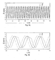
- a third order polynomial approximation of the anticipated dominant shift on the pretreatment step is used to correct the motion. This polynomial coincides well with the real movement on the first dynamics. Nevertheless, despite the variation of the angular velocity of the motor lower than 1%, the anticipated movement modeled by an unrepaired polynomial function diverges rapidly from the real movement.
- the Figures 4a and 4b present the real displacement (curve 19) measured on the graduated ruler, the estimated displacement (curve 20) on the anatomical images as well as the anticipated displacement (curve 21) modeled by a constant polynomial function.
- the latency period is constant.
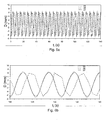
- the ex-vivo muscle was subjected in this experiment to a periodic translational movement of amplitude 14 mm and a period of about 5.6 s.
- the average lag time to compensate is about 1.9s.
- the curve 22 represents the actual displacement measured on the graduated ruler
- the curve 23 the estimated displacement on the anatomical images
- the curve 24 the anticipated displacement updated with each dynamic with a constant lag value.
- This method is more efficient than the previous one because the standard deviation measured between the measured and anticipated movement oscillates between 1mm at the beginning of the experiment and 2mm at the end.
- the delay to be compensated is mainly composed of the duration of acquisition of a dynamics (1s) and the delay of transmission and calculation ranging from 0.3s to 1.1s (0.9s on average).
- This variation in information processing time is partly related to the use of an operating system that is not real-time.
- This variation in the transmission delay induces a disturbance in the temporal location of the estimated movement which has repercussions on the anticipated movement.
- the anticipated movement is composed of a succession of disjoint trigonometric arches.
- the latency period to be compensated is obtained by comparing the time of the beginning of the last timed dynamic by a microcontroller with the time of the end of its treatment.
- the ex-vivo muscle was subjected to a periodic translational movement of amplitude 14 mm and a period of about 5.6 s.
- the curve 25 represents the actual displacement measured on the graduated ruler
- the curve 26 the estimated displacement on the anatomical images
- the curve 27 the anticipated displacement updated with each dynamic with the value of the measured latency period.
- This method is very efficient because the standard deviation measured between the measured and anticipated movement is 0.33mm.
- the anticipated movement is continuous with the exception of minute discontinuities allowing the adjustment of the period of the movement.
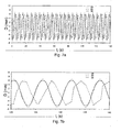
- FIGS. 7a and 7b show the anticipated movement obtained by using the reference technique to an atlas on the previously studied translation movement, with a latency period that is measured at each dynamic.
- Curve 28 represents the actual displacement measured on the ruler, the curve 29 the estimated displacement on the anatomical images, and the curve 30 the anticipated displacement.
- the anticipated displacement is discretized on 50 values corresponding to the 50 vector fields stored in the atlas. This discretization of the anticipated movement slightly decreases the precision of the motion determination.
- the standard deviation between the actual motion and the anticipated movement is 0.41mm instead of 0.33mm obtained using the dominant motion.
- the experimental error is on average 7.54mm.
- the anticipated movement allows a positioning accuracy of the treatment point at least 14 times more accurate than positioning without motion correction.
- the correction of the periodic movements is limited to the correction of the movements having a period greater than the duration of an acquisition of a dynamics. Indeed, according to Shanon-Nyquist's theorem, a sampling of at least two dynamics per period is necessary in order to reconstruct a complete period. In the experiments presented, the period of the movement performed was about 5.6 seconds, the acquisition of a dynamic per second therefore allowed a good reconstruction of the movement.
- thermometry artifacts Correction of thermometry artifacts in addition to the correction of the position of the treatment point
- the ex-vivo muscle was thus heated by the focused ultrasound device while successively subjecting it to different types of motion during heating.
- the ex-vivo muscle was initially subjected to an accidental translational movement of 14mm.
- the muscle was heated by the ultrasonic transducer emitting power of 75W electrical for 50 seconds.
- the accidental movement was carried out halfway through the duration of the heating.
- the Figures 8a to 8f compare temperature (during heating) and thermal dose maps (at the end of the experiment).
- the Figures 8a to 8c represent in fact the temperature maps respectively without correction of the thermometry and the position of the treatment point, with correction of the thermometry but without correction of the position of the treatment point, and finally with correction of the thermometry and the position of the treatment point.
- Figures 8d to 8f represent the thermal dose maps respectively without correction of the thermometry and the position of the treatment point, with correction of the thermometry but without correction of the position of the treatment point, and finally with correction of the thermometry and the position of the point treatment.
- the figure 9 shows the spatial distribution of the temperature along the vertical axis passing through the focal points presented on the temperature maps, with (curve 32) and without (curve 31) correction of the position of the treatment point.
- the Figure 10 shows the temporal evolution of the temperature in the zones heated during this experiment with (curve 35) and without (curve 33 before movement, curve 34 after movement) correction of the position of the treatment point.
- the temperature error made without correction of the thermometry, can reach 40 ° C. This artifact completely hides the heating performed. Similarly, the calculated thermal dose is unusable.
- the ex-vivo muscle was then subjected to a periodic translational movement of 14mm amplitude with a period of about 5.6s.
- the muscle was heated by the ultrasonic transducer emitting power of 100W electrical for 1 minute.
- the Figures 11a to 11f compare the temperature maps ( Figures 11a to 11c ) and thermal dose ( Figures 11d to 11f ), without correction of the thermometry and the position of the treatment point ( Figures 11a and 11d ), with correction of the thermometry but without correction of the position of the treatment point ( figures 11b and 11e ), and finally with correction of the thermometry and the position of the treatment point ( Figures 11c and 11f ).
- the Figure 12 shows the spatial distribution of temperature along the vertical axis. (corresponding to the axis of the movement made by the muscle) passing through the heating zones presented on the temperature maps, with (curve 37) and without (curve 36) correction of the position of the treatment point.
- the Figure 13 shows the temporal evolution of the temperature in the zones heated during this experiment with (curve 39) and without (curve 38) correction of the position of the treatment point.
- the temperature error made without correction of the thermometry can reach 40 ° C. This artifact completely hides the heating performed. Similarly, the calculated thermal dose is unusable.
- the heating zone is spread over 14mm.
- the induced heating does not lead to tissue necrosis because the rise in temperature is insufficient.
- a circular heating zone indicates that the movement has been correctly corrected.
- the continuous logarithmic form of the rise in temperature shows that the heating is not affected by the movement.
- the temperature reached by the tissue is twice as high as before. As the energy is still deposited on the same tissue region, necrosis has been induced. ,
- the most frequent and the most complex case to correct is the case of periodic elastic movements.
- the ex-vivo muscle was subjected to a periodical crushing movement of about 5.6s.
- the muscle was heated by the ultrasonic transducer emitting power of 100W electrical for 1 minute.
- the Figures 14a and 14b respectively show the anatomical images obtained at different positions of the movement and the fields associated motion vectors, estimated with respect to a reference central image.
- the Figures 15a to 15f compare the temperature maps ( Figures 15a to 15c ) and thermal dose ( Figures 15d to 15f ), without correction of the thermometry and the position of the treatment point ( Figures 15a and 15d ), with correction of the thermometry but without correction of the position of the treatment point ( Figures 15b and 15e ), and finally with correction of the thermometry and the position of the treatment point ( Figures 15c and 15f ).
- the Figure 16 shows the spatial distribution of the temperature along a vertical axis passing through the heating zones presented on the temperature maps, with (curve 41) and without (curve 40) correction of the position of the treatment point.
- the Figure 17 shows the temporal evolution of the temperature in the zones heated during this experiment with (curve 42) and without (curve 43) correction of the position of the treatment point.
- the temperature error made without correction of the thermometry can reach 300 ° C in 1 minute. Phase changes greater than 2 ⁇ appear between two successive dynamics, which induces a temperature error that accumulates over time. This artifact completely hides the heating performed. Similarly, the calculated thermal dose is unusable.
- the heating zone is spread out at 12mm.
- the induced heating does not lead to tissue necrosis because the rise in temperature is insufficient.
- a circular heating zone indicates that the movement has been accurately corrected.
- the continuous logarithmic form of the rise in temperature shows that the heating is not affected by the movement.
- the temperature reached by the fabric is higher than previously. As the energy is still deposited on the same tissue region, necrosis has been induced.
- thermometric correction also gives quality temperature mappings almost as good as those obtained without movement. These corrected temperature maps can be used to perform a temperature control as described above. Thus point and spatial temperature control techniques were applied to an ex vivo muscle subjected to rigid periodic motion.
- the one-shot PID servo-control algorithm of the temperature detailed above is performed with the temperature maps corrected and recalibrated at a central position of the movement. Thus all the calculations concerning the power necessary to control the temperature are established as if the fabric were motionless. Once the required power is determined the position of the focus point is adjusted every 100ms. with the periodic motion anticipation algorithm described above.
- the Figures 18a and 18b allow to compare the temperature control performed on an immobile ex-vivo muscle ( figure 18a ) and subjected to a rigid periodic motion ( figure 18b ).
- the movement of period 6s and amplitude 14mm is reconstructed on a pretreatment stage of 50 dynamics.
- each dynamic is acquired in 1s with voxels of 1,5x1,5x4,5mm 3 .
- the response time chosen to perform the feedback is 8s.
- the tissue parameters used to Anticipate the behavior of the fabric by Fourier transform are 0.1mm 2 / s for the diffusion coefficient and 0.006K / J for the absorption coefficient.
- the set temperature of 12 ° C between 160s and 300s is reached with and without movement of the fabric in the same way with an accuracy of 0.45 ° C. Given that the measurement noise intrinsic to the sequence used is 0.3 ° C, the correction of the thermometry and temperature control calculations induce very little noise on the rise obtained.
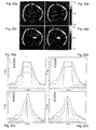
- the Figures 19a to 19d represent thermal maps corresponding to the dynamics at 114s ( Figures 19a and 19b ) and 183s ( Figures 19c and 19d ) of these two one-time servocontrols of the temperature made without movement ( Figures 19a and 19c ) and with movement ( Figures 19b and 19d ).
- Figures 20a to 20d represent the temperature along the two axes X and Z on an immobile ex-vivo muscle ( figures 20a in X and 20c in Z) or subjected to a rigid periodic movement ( figures 20b in X and 20d in Z), for the dynamics 103s (curves 46), 124s (curves 45) and 178s (curves 44).
- the Figures 21a and 21b allow to compare two heats performed with a spatial control of the temperature on a tissue respectively immobile or animated with a periodic translation movement.
- the amplitude of motion has been reduced to 8mm along the Z axis so that the focus point can be deflected over a range of 9mm in the perpendicular direction, the X axis. In this way, even when the tissue is in an extreme position of movement, the focal point does not deviate more than 6mm from its central position.
- the width of the voxels being 1.5 mm, the temperature control was performed on the 7 central voxels of the Z axis, a segment of width 9 mm.
- the curves 52, 51 and 50 respectively represent the minimum, average and maximum value of the temperature on these 7 voxels relative to the set temperature.
- the temperature rise follows the set point over the entire control zone with an accuracy of 0.5 ° C.
- the difference between the maximum temperature and the minimum temperature on the 7 slave voxels is 1.2 ° C on the immobile tissue and 1.3 ° C on the moving tissue.
- the Figures 22a to 22d represent thermal maps corresponding to the dynamics at 141s ( Figures 22a and 22b ) and at 215s ( Figures 22c and 22d ) of these two one-time servocontrols of the temperature made without movement ( Figures 22a and 22c ) and with movement ( Figures 22b and 22d ).
- the 9mm elongated segment along the X axis appears very distinctly even if the fabric is subjected to a periodic movement of 8mm in a perpendicular direction. Since the heated segment is not deformed, the focus points have followed the movement.
- Figures 23a to 23d represent the temperature along the two axes X and Z on an immobile ex-vivo muscle ( figures 23a in X and 23c in Z) or subjected to a rigid periodic movement ( figures 23b in X and 23d in Z), for the dynamics 145s (curves 55), 172s (curves 54) and 219s (curves 53).
- the rise in temperature obtained corresponds to the temperature set point plateau (curves 58 to 145s, curves 57 to 172s and curves 56 to 219s) along the X axis for each dynamic even if the effect of thermal diffusion opposes it, or that the fabric moves in a direction perpendicular to the Z axis.
- the spatial distribution of the heating on the moving tissue is slightly wider along the X and Z axes compared to the heating obtained on the motionless tissue. This is also explained by the presence of lobes all the more important that the point of focus must deviate from its central position.
- the focus point is shifted by half a voxel in the Z axis direction. This slight shift without serious consequences happens frequently since the spatial resolution of the MRI images used is voluntarily close to the size of the treatment point.
Landscapes
- Health & Medical Sciences (AREA)
- Animal Behavior & Ethology (AREA)
- Biomedical Technology (AREA)
- Nuclear Medicine, Radiotherapy & Molecular Imaging (AREA)
- Radiology & Medical Imaging (AREA)
- Life Sciences & Earth Sciences (AREA)
- Engineering & Computer Science (AREA)
- General Health & Medical Sciences (AREA)
- Public Health (AREA)
- Veterinary Medicine (AREA)
- Magnetic Resonance Imaging Apparatus (AREA)
- Thermotherapy And Cooling Therapy Devices (AREA)
- Surgical Instruments (AREA)
Claims (39)
- Vorrichtung zur thermischen Behandlung einer beweglichen Zielregion eines biologischen Gewebes, umfassend Mittel zur Energieerzeugung, die für eine nicht-invasive Wärmebehandlung bestimmt sind, und Kalkulationsmittel (6) zum Abschätzen einer Position der Zielregion ausgehend von einem Messsignal der Zielregion,
dadurch gekennzeichnet, dass die Vorrichtung außerdem Steuerungsmittel (7) umfasst, die einen Behandlungspunkt (P) in der Zielregion in Abhängigkeit von der geschätzten Position und einer Positionierungs-Verzögerungszeit, die zwischen einem Messen des Messsignals der Zielregion und der Positionierung des Behandlungspunkts (P) vergeht, derart positionieren, dass die Bewegung der Zielregion während der Positionierungs-Verzögerungszeit kompensiert wird. - Vorrichtung gemäß Anspruch 1, dadurch gekennzeichnet, dass die Positionierungs-Verzögerungszeit eine Latenzzeit umfasst, die auf die Abschätzung der Position der Zielregion durch die Kalkulationsmittel (6) zurückzuführen ist, so dass die Steuerungsmittel (7) in der Lage sind, die Bewegung der Zielregion während der Latenzzeit zu kompensieren.
- Vorrichtung gemäß irgendeinem der Ansprüche 1 oder 2, dadurch gekennzeichnet, dass die Positionierungs-Verzögerungszeit eine Antizipationszeit der Bewegung der Zielregion umfasst, so dass die Steuerungsmittel (7) in der Lage sind, die Bewegung der Zielregion während der Antizipationszeit zu antizipieren und zu kompensieren.
- Vorrichtung gemäß irgendeinem der Ansprüche 2 oder 3, dadurch gekennzeichnet, dass sie außerdem Mittel (10) zum Messen der Latenzzeit, die an die Steuerungsmittel (7) übermittelt wird, umfasst.
- Vorrichtung gemäß irgendeinem der vorhergehenden Ansprüche, dadurch gekennzeichnet, dass sie außerdem Modellierungsmittel zur Darstellung der Bewegung der Zielregion im Modell, ausgehend von einer Aufeinanderfolge von Messsignalen der Zielregion, umfasst.
- Vorrichtung gemäß Anspruch 5, dadurch gekennzeichnet, dass die Darstellung der Bewegung im Modell periodisch ist.
- Vorrichtung gemäß irgendeinem der Ansprüche 5 oder 6, dadurch gekennzeichnet, dass die Modellierungsmittel Mittel zur Lieferung einer Raumposition der Zielregion in Abhängigkeit von einer Zeitposition umfassen, wobei die Raum- und Zeitpositionen die Position der Zielregion definieren.
- Vorrichtung gemäß Anspruch 7, dadurch gekennzeichnet, dass die Kalkulationsmittel (6) Mittel zur Bestimmung einer geschätzten Raumposition der Zielregion unter Verwendung eines Algorithmus zur Verarbeitung des Messsignals der Zielregion umfassen.
- Vorrichtung gemäß Anspruch 8, dadurch gekennzeichnet, dass die Kalkulationsmittel (6) Mittel umfassen, die, entsprechend der Darstellung der Bewegung der Zielregion im Modell, die Bestimmung einer geschätzten Zeitposition der Zielregion, die der geschätzten Raumposition entspricht, durchführen.
- Vorrichtung gemäß Anspruch 9, dadurch gekennzeichnet, dass die Steuerungsmittel (7) Mittel zur Positionierung des Behandlungspunkts (P) entsprechend einer tatsächlichen Raumposition der Zielregion umfassen, wobei die tatsächliche Raumposition von einer tatsächlichen Zeitposition, entsprechend der Darstellung der Bewegung der Zielregion im Modell, abhängig ist, wobei die tatsächliche Zeitposition der geschätzten, um die Latenzzeit erhöhten Zeitposition entspricht.
- Vorrichtung gemäß Anspruch 10, dadurch gekennzeichnet, dass die Steuerungsmittel (7) außerdem Mittel zur Positionierung des Behandlungspunkts (P) zwischen den durch die Kalkulationsmittel (6) durchgeführten, aufeinander folgenden Abschätzungen einer ersten und einer zweiten Zeitposition, die jeweils ausgehend von einem ersten und einem zweiten Messsignal der Zielregion abgeschätzt wurden, umfassen, derart, das die Bewegung der Zielregion antizipiert wird.
- Vorrichtung gemäß Anspruch 11, dadurch gekennzeichnet, dass die Steuerungsmittel (7) Mittel zur Positionierung des Behandlungspunkts (P) gemäß einer antizipierten Raumposition umfassen, wobei die antizipierte Raumposition von einer antizipierten Zeitposition, entsprechend der Darstellung der Bewegung der Zielregion im Modell, abhängig ist, wobei die antizipierte Zeitposition der geschätzten, um die Latenzzeit und die Antizipationszeit erhöhten Zeitposition entspricht.
- Vorrichtung gemäß irgendeinem der vorhergehenden Ansprüche, dadurch gekennzeichnet, dass die Kalkulationsmittel (6) Mittel zur Bestimmung eines geschätzten Verschiebungsvektorfelds der Zielregion unter Verwendung eines Algorithmus zur Verarbeitung des Messsignals der Zielregion umfassen.
- Vorrichtung gemäß Anspruch 13, dadurch gekennzeichnet, dass die Steuerungsmittel (7) Mittel zur Positionierung des Behandlungspunkts (P) in der Zielregion in Abhängigkeit von dem geschätzten Verschiebungsvektorfeld umfassen.
- Vorrichtung gemäß irgendeinem der vorhergehenden Ansprüche, dadurch gekennzeichnet, dass sie Mittel zur Bilddarstellung (2) umfasst, welche Mittel zum Messen des Messsignals der Zielregion und Mittel zur Lieferung eines anatomischen Bilds der Zielregion, ausgehend von dem Messsignal der Zielregion, umfassen.
- Vorrichtung gemäß Anspruch 15, dadurch gekennzeichnet, dass die Bilddarstellungsmittel (2) außerdem Mittel zur Lieferung eines Phasenbilds der Zielregion, ausgehend von dem Messsignal der Zielregion, umfassen, um Temperaturänderungen in der Zielregion ausgehend von einem Vergleichsphasenbild zu verfolgen.
- Vorrichtung gemäß Anspruch 16, dadurch gekennzeichnet, dass die Kalkulationsmittel (6) außerdem Mittel zur Modifizierung des Vergleichsphasenbilds umfassen, um eine Temperaturstörung, die durch eine Bewegung der Zielregion hervorgerufen wird, zu korrigieren.
- Vorrichtung gemäß Anspruch 17, dadurch gekennzeichnet, dass die Kalkulationsmittel (6) Mittel zur Modifizierung des Vergleichsphasenbilds in Abhängigkeit einer Historie von Phasenbildern umfassen.
- Vorrichtung gemäß irgendeinem der Ansprüche 15 bis 18, dadurch gekennzeichnet, dass sie außerdem Mittel zur Regulation einer Strahlung, die auf den Behandlungspunkt (P) in der Zielregion angewendet wird, umfasst, so dass die zeitliche Temperaturverteilung der Zielregion mit einer Vorgabe der räumlichen Temperaturverteilung übereinstimmt.
- Vorrichtung gemäß Anspruch 19, dadurch gekennzeichnet, dass die Regulationsmittel Mittel zur Regulierung der angewendeten Strahlung in Abhängigkeit von der räumlichen Temperaturverteilung in der Zielregion und einer Vorgabe der räumlichen Temperaturverteilung gemäß einem Regulationsgesetz, welches einen Proportional-Integral-Differential-Term umfasst, umfassen.
- Verfahren zur Positionierung eines Punkts (P) bei der thermischen, nicht-invasiven Behandlung einer beweglichen Zielregion eines biologischen Gewebes, umfassend die folgenden Schritte:- Messen der Zielregion zum Erhalt eines Messsignals der Zielregion,- Abschätzen einer Position der Zielregion, ausgehend von dem Messsignal der Zielregion, durch Kalkulationsmittel (6),dadurch gekennzeichnet, dass das Verfahren einen Schritt beinhaltet, in dem ein Behandlungspunkt (P) in der Zielregion durch Steuerungsmittel (7) positioniert wird, wobei die Positionierung abhängig ist von der geschätzten Position und von einer Positionierungs-Verzögerungszeit, die zwischen dem Messen des Messsignals der Zielregion und der Positionierung des Behandlungspunkts (P) vergeht, so dass die Bewegung der Zielregion während der Positionierungs-Verzögerungszeit kompensiert wird.
- Verfahren gemäß Anspruch 21, dadurch gekennzeichnet, dass die Positionierungs-Verzögerungszeit eine Latenzzeit umfasst, die auf die Abschätzung der Position der Zielregion durch die Kalkulationsmittel (6) zurückzuführen ist, so dass die Bewegung der Zielregion während der Latenzzeit kompensiert wird.
- Verfahren gemäß irgendeinem der Ansprüche 21 oder 22, dadurch gekennzeichnet, dass die Positionierungs-Verzögerungszeit eine Antizipationszeit der Bewegung der Zielregion umfasst, so dass die Bewegung der Zielregion während der Antizipationszeit antizipiert und kompensiert wird.
- Verfahren gemäß irgendeinem der Ansprüche 22 oder 23, dadurch gekennzeichnet, dass es außerdem einen Schritt umfasst, in dem in Echtzeit die Latenzzeit durch die Messmittel (10) gemessen wird.
- Verfahren gemäß irgendeinem der Ansprüche 21 bis 24, dadurch gekennzeichnet, dass es außerdem einen Schritt umfasst, in dem die Bewegung der Zielregion, ausgehend von einer Aufeinanderfolge von Messsignalen der Zielregion, im Modell dargestellt wird.
- Verfahren gemäß Anspruch 25, dadurch gekennzeichnet, dass ein Zeitraum-Typ für die Darstellung der Bewegung der Zielregion im Modell bestimmt wird.
- Verfahren gemäß irgendeinem der Ansprüche 25 oder 26, dadurch gekennzeichnet, dass die Position der Zielregion durch eine Raumposition in Abhängigkeit von einer Zeitposition im Modell dargestellt wird.
- Verfahren gemäß Anspruch 27, dadurch gekennzeichnet, dass die Abschätzung der Position der Zielregion folgende Schritte umfasst:- Bestimmung einer geschätzten Raumposition der Zielregion unter Verwendung eines Algorithmus zur Verarbeitung des Messsignals der Zielregion, und- Bestimmung, entsprechend der Darstellung der Bewegung der Zielregion im Modell, einer geschätzten Zeitposition der Zielregion, die der geschätzten Raumposition entspricht.
- Verfahren gemäß Anspruch 28, dadurch gekennzeichnet, dass die Positionierung des Behandlungspunkts (P) folgende Schritte umfasst:- Bestimmung einer tatsächlichen Zeitposition der Zielregion, wobei die tatsächliche Zeitposition der geschätzten, um die Latenzzeit erhöhten Zeitposition entspricht,- Bestimmung einer tatsächlichen Raumposition der Zielregion entsprechend der Darstellung der Bewegung der Zielregion im Modell, in Abhängigkeit von der tatsächlichen Zeitposition, und- Positionieren des Behandlungspunkts (P) entsprechend der tatsächlichen Raumposition.
- Verfahren gemäß Anspruch 29, dadurch gekennzeichnet, dass die Positionierung des Behandlungspunkts (P) folgende zusätzliche Schritte umfasst:- Bestimmung einer antizipierten Zeitposition der Zielregion, wobei die antizipierte Zeitposition der geschätzten, um die Latenzzeit und die Antizipationszeit erhöhten Zeitposition entspricht,- Bestimmung einer antizipierten Raumposition der Zielregion, entsprechend der Darstellung der Bewegung der Zielregion im Modell, in Abhängigkeit von der antizipierten Zeitposition, und- Positionieren des Behandlungspunkts (P) entsprechend der antizipierten Raumposition.
- Verfahren gemäß Anspruch 30, dadurch gekennzeichnet, dass die zusätzlichen Schritte der Positionierung des Behandlungspunkts (P) solange wiederholt werden, bis eine neue geschätzte Zeitposition bestimmt wurde.
- Verfahren gemäß irgendeinem der Ansprüche 23 bis 31, dadurch gekennzeichnet, dass es außerdem einen Schritt beinhaltet, in dem ein geschätztes Verschiebungsvektorfeld der Zielregion unter Verwendung eines Algorithmus zur Verarbeitung des Messsignals der Zielregion bestimmt wird.
- Verfahren gemäß Anspruch 32, dadurch gekennzeichnet, dass der Behandlungspunkt in der Zielregion in Abhängigkeit von dem geschätzten Verschiebungsvektorfeld positioniert wird.
- Verfahren gemäß irgendeinem der Ansprüche 23 bis 33, dadurch gekennzeichnet, dass das Messsignal der Zielregion ein anatomisches Bild der Zielregion für die Positionierung des Behandlungspunkts liefert.
- Verfahren gemäß Anspruch 34, dadurch gekennzeichnet, dass das Messsignal der Zielregion außerdem ein Phasenbild der Zielregion liefert.
- Verfahren gemäß Anspruch 35, dadurch gekennzeichnet, dass es außerdem die folgenden Schritte umfasst:- Bestimmung eines Vergleichsphasenbilds,- Vergleichen des erhaltenen Phasenbilds mit dem Vergleichsphasenbild zum Verfolgen von Temperaturänderungen der Zielregion.
- Verfahren gemäß Anspruch 36, dadurch gekennzeichnet, dass ein Vergleichsphasenbild ausgehend von einer Historie von Phasenbildern bestimmt wird.
- Verfahren gemäß Anspruch 37, dadurch gekennzeichnet, dass es außerdem einen Schritt umfasst, in dem eine Strahlung, die auf den Behandlungspunkt (P) in der Zielregion angewendet wird, reguliert wird, um die räumliche Temperaturverteilung der Zielregion mit einer Vorgabe der räumlichen Temperaturverteilung in Übereinstimmung zu bringen.
- Verfahren gemäß Anspruch 38, dadurch gekennzeichnet, dass die angewendete Strahlung in Abhängigkeit von der räumlichen Temperaturverteilung der Zielregion und einer Vorgabe der räumlichen Temperaturverteilung gemäß einem Regulationsgesetz, welches einen Proportional-Integral-Differential-Term umfasst, reguliert wird.
Applications Claiming Priority (2)
| Application Number | Priority Date | Filing Date | Title |
|---|---|---|---|
| FR0509885A FR2891153B1 (fr) | 2005-09-28 | 2005-09-28 | Dispositif de traitement thermique de tissus biologiques en mouvement |
| PCT/EP2006/065832 WO2007036409A1 (fr) | 2005-09-28 | 2006-08-30 | Dispositif de traitement thermique de tissus biologiques en mouvement, et procede associe |
Publications (2)
| Publication Number | Publication Date |
|---|---|
| EP1933729A1 EP1933729A1 (de) | 2008-06-25 |
| EP1933729B1 true EP1933729B1 (de) | 2011-10-19 |
Family
ID=36282622
Family Applications (1)
| Application Number | Title | Priority Date | Filing Date |
|---|---|---|---|
| EP06778412A Ceased EP1933729B1 (de) | 2005-09-28 | 2006-08-30 | Vorrichtung zur wärmebehandlung von beweglichem biologischem gewebe und relevantes positionierung verfahren |
Country Status (7)
| Country | Link |
|---|---|
| US (1) | US20090131782A1 (de) |
| EP (1) | EP1933729B1 (de) |
| JP (1) | JP5126894B2 (de) |
| AT (1) | ATE529055T1 (de) |
| CA (1) | CA2623887C (de) |
| FR (1) | FR2891153B1 (de) |
| WO (1) | WO2007036409A1 (de) |
Families Citing this family (13)
| Publication number | Priority date | Publication date | Assignee | Title |
|---|---|---|---|---|
| US9146289B2 (en) * | 2009-12-23 | 2015-09-29 | General Electric Company | Targeted thermal treatment of human tissue through respiratory cycles using ARMA modeling |
| US8725232B2 (en) * | 2009-12-28 | 2014-05-13 | Koninklijke Philips N.V. | Therapeutic apparatus |
| EP2500741A1 (de) | 2011-03-17 | 2012-09-19 | Koninklijke Philips Electronics N.V. | Magnetresonanzmessung von Ultraschalleigenschaften |
| FR2975886B1 (fr) * | 2011-05-30 | 2013-06-28 | Univ Bordeaux Segalen | Procede de ciblage d'une region d'interet d'un tissu biologique d'un patient et dispositif associe |
| EP2811901B1 (de) * | 2012-02-06 | 2016-06-08 | Insightec, Ltd. | Referenzbibliothekserweiterung während der bildgebung von beweglichen organen |
| US10420608B2 (en) | 2014-05-20 | 2019-09-24 | Verily Life Sciences Llc | System for laser ablation surgery |
| DE102014218924A1 (de) * | 2014-09-19 | 2016-03-24 | Siemens Aktiengesellschaft | Ermittlung einer Position eines Objekts mittels MRT-Aufnahmen |
| EP3665267A1 (de) * | 2017-08-07 | 2020-06-17 | Novozymes A/S | Verwendung von fca-steuerung auf ph-basis |
| US10634559B2 (en) * | 2018-04-18 | 2020-04-28 | Raytheon Company | Spectrally-scanned hyperspectral electro-optical sensor for instantaneous situational awareness |
| JP6943826B2 (ja) | 2018-09-28 | 2021-10-06 | 三菱パワー株式会社 | 熱機器の内部状態推定方法及び装置 |
| EP3877989B1 (de) * | 2018-11-07 | 2025-01-01 | Brainlab AG | Kompartimentierter dynamischer atlas |
| CN112947091B (zh) * | 2021-03-26 | 2022-06-10 | 福州大学 | 基于pid控制的生物组织内磁纳米粒子产热优化方法 |
| CN113341715A (zh) * | 2021-06-04 | 2021-09-03 | 福州大学 | 基于比例积分控制的生物组织内扩散磁流体产热分析方法 |
Family Cites Families (18)
| Publication number | Priority date | Publication date | Assignee | Title |
|---|---|---|---|---|
| JPS63260546A (ja) * | 1987-04-17 | 1988-10-27 | オリンパス光学工業株式会社 | 超音波治療装置 |
| US5178135A (en) * | 1987-04-16 | 1993-01-12 | Olympus Optical Co., Ltd. | Therapeutical apparatus of extracorporeal type |
| JP3325300B2 (ja) * | 1992-02-28 | 2002-09-17 | 株式会社東芝 | 超音波治療装置 |
| EP0811171B1 (de) * | 1995-12-14 | 2005-07-27 | Koninklijke Philips Electronics N.V. | Verfahren und gerät zum erhitzen mit ultraschall, gesteuert durch bilderzeugung mit magnetischer resonanz |
| FR2779548B1 (fr) * | 1998-06-05 | 2000-11-10 | Thomson Csf | Procede de suivi dynamique de l'evolution de milieux deformables, et de prediction de leur evolution |
| US6501981B1 (en) * | 1999-03-16 | 2002-12-31 | Accuray, Inc. | Apparatus and method for compensating for respiratory and patient motions during treatment |
| US6675034B2 (en) * | 2001-04-19 | 2004-01-06 | Sunnybrook And Women's Health Sciences Centre | Magnetic resonance imaging using direct, continuous real-time imaging for motion compensation |
| JP4060615B2 (ja) * | 2002-03-05 | 2008-03-12 | 株式会社東芝 | 画像処理装置及び超音波診断装置 |
| US7769427B2 (en) * | 2002-07-16 | 2010-08-03 | Magnetics, Inc. | Apparatus and method for catheter guidance control and imaging |
| JP4202697B2 (ja) * | 2002-08-12 | 2008-12-24 | 株式会社東芝 | 超音波診断装置、超音波画像表示装置および超音波画像表示方法 |
| DE10245943B4 (de) * | 2002-09-30 | 2008-06-26 | Siemens Ag | Verfahren zur Erzeugung von CT-Bildern eines periodisch bewegten Organs und CT-Gerät zur Durchführung eines solchen Verfahrens |
| US6994673B2 (en) * | 2003-01-16 | 2006-02-07 | Ge Ultrasound Israel, Ltd | Method and apparatus for quantitative myocardial assessment |
| WO2004075987A1 (en) * | 2003-02-28 | 2004-09-10 | Koninklijke Philips Electronics, N.V. | Motion-tracking improvements for hifu ultrasound therapy |
| EP2386246A1 (de) * | 2003-05-21 | 2011-11-16 | Koninklijke Philips Electronics N.V. | Vorrichtung und Verfahren zum Navigieren eines Katheters |
| CN100542489C (zh) * | 2003-05-21 | 2009-09-23 | 皇家飞利浦电子股份有限公司 | 用于引导导管的装置和方法 |
| US10342558B2 (en) * | 2003-09-30 | 2019-07-09 | Koninklijke Philips N.V. | Target tracking method and apparatus for radiation treatment planning and delivery |
| FR2869548B1 (fr) * | 2004-04-29 | 2006-07-28 | Centre Nat Rech Scient Cnrse | Ensemble de traitement thermique de tissus biologiques. |
| US8095203B2 (en) * | 2004-07-23 | 2012-01-10 | Varian Medical Systems, Inc. | Data processing for real-time tracking of a target in radiation therapy |
-
2005
- 2005-09-28 FR FR0509885A patent/FR2891153B1/fr not_active Expired - Fee Related
-
2006
- 2006-08-30 EP EP06778412A patent/EP1933729B1/de not_active Ceased
- 2006-08-30 WO PCT/EP2006/065832 patent/WO2007036409A1/fr not_active Ceased
- 2006-08-30 CA CA2623887A patent/CA2623887C/fr not_active Expired - Fee Related
- 2006-08-30 AT AT06778412T patent/ATE529055T1/de not_active IP Right Cessation
- 2006-08-30 JP JP2008532699A patent/JP5126894B2/ja not_active Expired - Fee Related
- 2006-08-30 US US11/992,902 patent/US20090131782A1/en not_active Abandoned
Also Published As
| Publication number | Publication date |
|---|---|
| JP2009509600A (ja) | 2009-03-12 |
| WO2007036409A1 (fr) | 2007-04-05 |
| FR2891153A1 (fr) | 2007-03-30 |
| EP1933729A1 (de) | 2008-06-25 |
| CA2623887A1 (fr) | 2007-04-05 |
| CA2623887C (fr) | 2014-04-01 |
| US20090131782A1 (en) | 2009-05-21 |
| JP5126894B2 (ja) | 2013-01-23 |
| ATE529055T1 (de) | 2011-11-15 |
| FR2891153B1 (fr) | 2008-08-22 |
Similar Documents
| Publication | Publication Date | Title |
|---|---|---|
| CA2623887C (fr) | Dispositif de traitement thermique de tissus biologiques en mouvement, et procede associe | |
| De Senneville et al. | Real‐time adaptive methods for treatment of mobile organs by MRI‐controlled high‐intensity focused ultrasound | |
| CA2384526C (fr) | Ensemble de traitement thermique de tissus biologiques et procede de mise en oeuvre de cet ensemble | |
| CN103460069B (zh) | 加速的磁共振测温法 | |
| EP2519324B1 (de) | Therapeutische vorrichtung | |
| Puccini et al. | Simulations of thermal tissue coagulation and their value for the planning and monitoring of laser‐induced interstitial thermotherapy (LITT) | |
| Jensen et al. | Real-time temperature estimation and monitoring of HIFU ablation through a combined modeling and passive acoustic mapping approach | |
| EP2121136A1 (de) | Verfahren zur optimierung der wellenfokalisierung durch ein aberrationseinsatzelement | |
| WO2005058154A1 (en) | Method for monitoring of analytes in biological samples using low coherence interferometry | |
| CN108478192A (zh) | 一种用于估测皮肤组织微血管深度的测量系统 | |
| Fuentes et al. | Computational modeling and real-time control of patient-specific laser treatment of cancer | |
| Kim et al. | Laser–tissue interaction simulation considering skin-specific data to predict photothermal damage lesions during laser irradiation | |
| Majaron et al. | Monte Carlo simulation of radiation transport in human skin with rigorous treatment of curved tissue boundaries | |
| Park et al. | Application of ultrasound thermal imaging for monitoring laser ablation in ex vivo cardiac tissue | |
| Arnold et al. | Identification of tissue optical properties during thermal laser‐tissue interactions: An ensemble Kalman filter‐based approach | |
| Fuentes et al. | An inverse problem approach to recovery of in vivo nanoparticle concentrations from thermal image monitoring of MR-guided laser induced thermal therapy | |
| Johnson et al. | Development and validation of a MRgHIFU non-invasive tissue acoustic property estimation technique | |
| US20170336483A1 (en) | System and method for device tracking via magnetic resonance imaging with light-modulated magnetic susceptibility markers | |
| Fuentes et al. | Adaptive real-time bioheat transfer models for computer-driven MR-guided laser induced thermal therapy | |
| Li et al. | Determination of optical absorption coefficient with focusing photoacoustic imaging | |
| Lv et al. | Monitoring acoustic cavitation effects in tissues under the action of HIFU based on ultrasound images | |
| CA2445313C (fr) | Ensemble pour le traitement thermique de tissus biologiques | |
| Vidovič et al. | Quantitative analysis of hemodynamics in bruised skin using photothermal depth profiling | |
| Abdalsalam et al. | Non-invasive glucose monitoring using scattering spectroscopy | |
| Ren et al. | Optoacoustic quantitative in vitro detection of diabetes mellitus involving the comprehensive impacts based on improved quantum particle swarm optimized wavelet neural network |
Legal Events
| Date | Code | Title | Description |
|---|---|---|---|
| PUAI | Public reference made under article 153(3) epc to a published international application that has entered the european phase |
Free format text: ORIGINAL CODE: 0009012 |
|
| 17P | Request for examination filed |
Effective date: 20080326 |
|
| AK | Designated contracting states |
Kind code of ref document: A1 Designated state(s): AT BE BG CH CY CZ DE DK EE ES FI FR GB GR HU IE IS IT LI LT LU LV MC NL PL PT RO SE SI SK TR |
|
| RAP1 | Party data changed (applicant data changed or rights of an application transferred) |
Owner name: IMAGE GUIDED THERAPY Owner name: CENTRE NATIONAL DE LA RECHERCHE SCIENTIFIQUE |
|
| 17Q | First examination report despatched |
Effective date: 20100330 |
|
| GRAP | Despatch of communication of intention to grant a patent |
Free format text: ORIGINAL CODE: EPIDOSNIGR1 |
|
| RTI1 | Title (correction) |
Free format text: DEVICE FOR HEAT TREATING MOVING BIOLOGICAL TISSUES, AND RELATED POSITIONING METHOD |
|
| DAX | Request for extension of the european patent (deleted) | ||
| GRAS | Grant fee paid |
Free format text: ORIGINAL CODE: EPIDOSNIGR3 |
|
| GRAA | (expected) grant |
Free format text: ORIGINAL CODE: 0009210 |
|
| AK | Designated contracting states |
Kind code of ref document: B1 Designated state(s): AT BE BG CH CY CZ DE DK EE ES FI FR GB GR HU IE IS IT LI LT LU LV MC NL PL PT RO SE SI SK TR |
|
| REG | Reference to a national code |
Ref country code: GB Ref legal event code: FG4D Free format text: NOT ENGLISH |
|
| REG | Reference to a national code |
Ref country code: CH Ref legal event code: EP |
|
| REG | Reference to a national code |
Ref country code: IE Ref legal event code: FG4D |
|
| REG | Reference to a national code |
Ref country code: DE Ref legal event code: R096 Ref document number: 602006025267 Country of ref document: DE Effective date: 20120105 |
|
| REG | Reference to a national code |
Ref country code: NL Ref legal event code: T3 |
|
| LTIE | Lt: invalidation of european patent or patent extension |
Effective date: 20111019 |
|
| REG | Reference to a national code |
Ref country code: AT Ref legal event code: MK05 Ref document number: 529055 Country of ref document: AT Kind code of ref document: T Effective date: 20111019 |
|
| PG25 | Lapsed in a contracting state [announced via postgrant information from national office to epo] |
Ref country code: IS Free format text: LAPSE BECAUSE OF FAILURE TO SUBMIT A TRANSLATION OF THE DESCRIPTION OR TO PAY THE FEE WITHIN THE PRESCRIBED TIME-LIMIT Effective date: 20120219 Ref country code: LT Free format text: LAPSE BECAUSE OF FAILURE TO SUBMIT A TRANSLATION OF THE DESCRIPTION OR TO PAY THE FEE WITHIN THE PRESCRIBED TIME-LIMIT Effective date: 20111019 |
|
| REG | Reference to a national code |
Ref country code: IE Ref legal event code: FD4D |
|
| PG25 | Lapsed in a contracting state [announced via postgrant information from national office to epo] |
Ref country code: SE Free format text: LAPSE BECAUSE OF FAILURE TO SUBMIT A TRANSLATION OF THE DESCRIPTION OR TO PAY THE FEE WITHIN THE PRESCRIBED TIME-LIMIT Effective date: 20111019 Ref country code: GR Free format text: LAPSE BECAUSE OF FAILURE TO SUBMIT A TRANSLATION OF THE DESCRIPTION OR TO PAY THE FEE WITHIN THE PRESCRIBED TIME-LIMIT Effective date: 20120120 Ref country code: LV Free format text: LAPSE BECAUSE OF FAILURE TO SUBMIT A TRANSLATION OF THE DESCRIPTION OR TO PAY THE FEE WITHIN THE PRESCRIBED TIME-LIMIT Effective date: 20111019 Ref country code: SI Free format text: LAPSE BECAUSE OF FAILURE TO SUBMIT A TRANSLATION OF THE DESCRIPTION OR TO PAY THE FEE WITHIN THE PRESCRIBED TIME-LIMIT Effective date: 20111019 Ref country code: PT Free format text: LAPSE BECAUSE OF FAILURE TO SUBMIT A TRANSLATION OF THE DESCRIPTION OR TO PAY THE FEE WITHIN THE PRESCRIBED TIME-LIMIT Effective date: 20120220 |
|
| PG25 | Lapsed in a contracting state [announced via postgrant information from national office to epo] |
Ref country code: CY Free format text: LAPSE BECAUSE OF FAILURE TO SUBMIT A TRANSLATION OF THE DESCRIPTION OR TO PAY THE FEE WITHIN THE PRESCRIBED TIME-LIMIT Effective date: 20111019 |
|
| PG25 | Lapsed in a contracting state [announced via postgrant information from national office to epo] |
Ref country code: SK Free format text: LAPSE BECAUSE OF FAILURE TO SUBMIT A TRANSLATION OF THE DESCRIPTION OR TO PAY THE FEE WITHIN THE PRESCRIBED TIME-LIMIT Effective date: 20111019 Ref country code: IE Free format text: LAPSE BECAUSE OF FAILURE TO SUBMIT A TRANSLATION OF THE DESCRIPTION OR TO PAY THE FEE WITHIN THE PRESCRIBED TIME-LIMIT Effective date: 20111019 Ref country code: BG Free format text: LAPSE BECAUSE OF FAILURE TO SUBMIT A TRANSLATION OF THE DESCRIPTION OR TO PAY THE FEE WITHIN THE PRESCRIBED TIME-LIMIT Effective date: 20120119 Ref country code: EE Free format text: LAPSE BECAUSE OF FAILURE TO SUBMIT A TRANSLATION OF THE DESCRIPTION OR TO PAY THE FEE WITHIN THE PRESCRIBED TIME-LIMIT Effective date: 20111019 Ref country code: DK Free format text: LAPSE BECAUSE OF FAILURE TO SUBMIT A TRANSLATION OF THE DESCRIPTION OR TO PAY THE FEE WITHIN THE PRESCRIBED TIME-LIMIT Effective date: 20111019 Ref country code: CZ Free format text: LAPSE BECAUSE OF FAILURE TO SUBMIT A TRANSLATION OF THE DESCRIPTION OR TO PAY THE FEE WITHIN THE PRESCRIBED TIME-LIMIT Effective date: 20111019 |
|
| PLBE | No opposition filed within time limit |
Free format text: ORIGINAL CODE: 0009261 |
|
| STAA | Information on the status of an ep patent application or granted ep patent |
Free format text: STATUS: NO OPPOSITION FILED WITHIN TIME LIMIT |
|
| PG25 | Lapsed in a contracting state [announced via postgrant information from national office to epo] |
Ref country code: IT Free format text: LAPSE BECAUSE OF FAILURE TO SUBMIT A TRANSLATION OF THE DESCRIPTION OR TO PAY THE FEE WITHIN THE PRESCRIBED TIME-LIMIT Effective date: 20111019 Ref country code: PL Free format text: LAPSE BECAUSE OF FAILURE TO SUBMIT A TRANSLATION OF THE DESCRIPTION OR TO PAY THE FEE WITHIN THE PRESCRIBED TIME-LIMIT Effective date: 20111019 Ref country code: RO Free format text: LAPSE BECAUSE OF FAILURE TO SUBMIT A TRANSLATION OF THE DESCRIPTION OR TO PAY THE FEE WITHIN THE PRESCRIBED TIME-LIMIT Effective date: 20111019 |
|
| 26N | No opposition filed |
Effective date: 20120720 |
|
| REG | Reference to a national code |
Ref country code: DE Ref legal event code: R097 Ref document number: 602006025267 Country of ref document: DE Effective date: 20120720 |
|
| REG | Reference to a national code |
Ref country code: DE Ref legal event code: R082 Ref document number: 602006025267 Country of ref document: DE Representative=s name: KILIAN KILIAN & PARTNER, DE Ref country code: DE Ref legal event code: R082 Ref document number: 602006025267 Country of ref document: DE Representative=s name: KILIAN KILIAN & PARTNER MBB PATENTANWAELTE, DE |
|
| PG25 | Lapsed in a contracting state [announced via postgrant information from national office to epo] |
Ref country code: AT Free format text: LAPSE BECAUSE OF FAILURE TO SUBMIT A TRANSLATION OF THE DESCRIPTION OR TO PAY THE FEE WITHIN THE PRESCRIBED TIME-LIMIT Effective date: 20111019 |
|
| BERE | Be: lapsed |
Owner name: CENTRE NATIONAL DE LA RECHERCHE SCIENTIFIQUE Effective date: 20120831 Owner name: IMAGE GUIDED THERAPY Effective date: 20120831 |
|
| REG | Reference to a national code |
Ref country code: CH Ref legal event code: PL |
|
| PG25 | Lapsed in a contracting state [announced via postgrant information from national office to epo] |
Ref country code: MC Free format text: LAPSE BECAUSE OF NON-PAYMENT OF DUE FEES Effective date: 20120831 |
|
| PG25 | Lapsed in a contracting state [announced via postgrant information from national office to epo] |
Ref country code: ES Free format text: LAPSE BECAUSE OF FAILURE TO SUBMIT A TRANSLATION OF THE DESCRIPTION OR TO PAY THE FEE WITHIN THE PRESCRIBED TIME-LIMIT Effective date: 20120130 Ref country code: LI Free format text: LAPSE BECAUSE OF NON-PAYMENT OF DUE FEES Effective date: 20120831 Ref country code: CH Free format text: LAPSE BECAUSE OF NON-PAYMENT OF DUE FEES Effective date: 20120831 |
|
| PG25 | Lapsed in a contracting state [announced via postgrant information from national office to epo] |
Ref country code: BE Free format text: LAPSE BECAUSE OF NON-PAYMENT OF DUE FEES Effective date: 20120831 |
|
| PG25 | Lapsed in a contracting state [announced via postgrant information from national office to epo] |
Ref country code: FI Free format text: LAPSE BECAUSE OF FAILURE TO SUBMIT A TRANSLATION OF THE DESCRIPTION OR TO PAY THE FEE WITHIN THE PRESCRIBED TIME-LIMIT Effective date: 20111019 |
|
| PG25 | Lapsed in a contracting state [announced via postgrant information from national office to epo] |
Ref country code: TR Free format text: LAPSE BECAUSE OF FAILURE TO SUBMIT A TRANSLATION OF THE DESCRIPTION OR TO PAY THE FEE WITHIN THE PRESCRIBED TIME-LIMIT Effective date: 20111019 |
|
| PG25 | Lapsed in a contracting state [announced via postgrant information from national office to epo] |
Ref country code: LU Free format text: LAPSE BECAUSE OF NON-PAYMENT OF DUE FEES Effective date: 20120830 |
|
| PG25 | Lapsed in a contracting state [announced via postgrant information from national office to epo] |
Ref country code: HU Free format text: LAPSE BECAUSE OF FAILURE TO SUBMIT A TRANSLATION OF THE DESCRIPTION OR TO PAY THE FEE WITHIN THE PRESCRIBED TIME-LIMIT Effective date: 20060830 |
|
| REG | Reference to a national code |
Ref country code: FR Ref legal event code: PLFP Year of fee payment: 11 |
|
| REG | Reference to a national code |
Ref country code: FR Ref legal event code: PLFP Year of fee payment: 12 |
|
| REG | Reference to a national code |
Ref country code: FR Ref legal event code: PLFP Year of fee payment: 13 |
|
| PGFP | Annual fee paid to national office [announced via postgrant information from national office to epo] |
Ref country code: DE Payment date: 20180813 Year of fee payment: 13 Ref country code: FR Payment date: 20180830 Year of fee payment: 13 Ref country code: NL Payment date: 20180712 Year of fee payment: 13 |
|
| PGFP | Annual fee paid to national office [announced via postgrant information from national office to epo] |
Ref country code: GB Payment date: 20180821 Year of fee payment: 13 |
|
| REG | Reference to a national code |
Ref country code: DE Ref legal event code: R119 Ref document number: 602006025267 Country of ref document: DE |
|
| REG | Reference to a national code |
Ref country code: NL Ref legal event code: MM Effective date: 20190901 |
|
| GBPC | Gb: european patent ceased through non-payment of renewal fee |
Effective date: 20190830 |
|
| PG25 | Lapsed in a contracting state [announced via postgrant information from national office to epo] |
Ref country code: FR Free format text: LAPSE BECAUSE OF NON-PAYMENT OF DUE FEES Effective date: 20190831 Ref country code: DE Free format text: LAPSE BECAUSE OF NON-PAYMENT OF DUE FEES Effective date: 20200303 Ref country code: NL Free format text: LAPSE BECAUSE OF NON-PAYMENT OF DUE FEES Effective date: 20190901 |
|
| PG25 | Lapsed in a contracting state [announced via postgrant information from national office to epo] |
Ref country code: GB Free format text: LAPSE BECAUSE OF NON-PAYMENT OF DUE FEES Effective date: 20190830 |