EP1933366B1 - Vorrichtung zur Massenanalyse von Ionen - Google Patents
Vorrichtung zur Massenanalyse von Ionen Download PDFInfo
- Publication number
- EP1933366B1 EP1933366B1 EP07405338.0A EP07405338A EP1933366B1 EP 1933366 B1 EP1933366 B1 EP 1933366B1 EP 07405338 A EP07405338 A EP 07405338A EP 1933366 B1 EP1933366 B1 EP 1933366B1
- Authority
- EP
- European Patent Office
- Prior art keywords
- ions
- field
- mass spectrometer
- time
- ion source
- Prior art date
- Legal status (The legal status is an assumption and is not a legal conclusion. Google has not performed a legal analysis and makes no representation as to the accuracy of the status listed.)
- Active
Links
Images


Classifications
-
- H—ELECTRICITY
- H01—ELECTRIC ELEMENTS
- H01J—ELECTRIC DISCHARGE TUBES OR DISCHARGE LAMPS
- H01J49/00—Particle spectrometers or separator tubes
- H01J49/26—Mass spectrometers or separator tubes
- H01J49/34—Dynamic spectrometers
- H01J49/40—Time-of-flight spectrometers
-
- H—ELECTRICITY
- H01—ELECTRIC ELEMENTS
- H01J—ELECTRIC DISCHARGE TUBES OR DISCHARGE LAMPS
- H01J49/00—Particle spectrometers or separator tubes
- H01J49/26—Mass spectrometers or separator tubes
- H01J49/34—Dynamic spectrometers
- H01J49/42—Stability-of-path spectrometers, e.g. monopole, quadrupole, multipole, farvitrons
- H01J49/4205—Device types
- H01J49/421—Mass filters, i.e. deviating unwanted ions without trapping
- H01J49/4215—Quadrupole mass filters
Definitions
- the invention relates to an apparatus for mass analysis of ions comprising a high current ion source, a time-of-flight mass spectrometer for analysis of transmitted ions and a filter for segmenting incoming ions according to their m/q ratio into a first group of ions and into a second group of ions, whereas the mass filter is coupled to the ion source and whereas the mass filter and the time-of-flight mass spectrometer are arranged in such a way that the ions of the first group are transmitted to the mass spectrometer and that the ions of the second group are not transmitted to the mass spectrometer.
- the invention further relates to an arrangement for mass analysis of particles as well as to methods for mass analysis of ions and particles.
- Mass spectrometry is a method of analysis that can be applied in a wide field of different applications. Especially time-of-flight mass spectrometers (TOFMS) can be used for chemical and biological analysis in many different fields, including the analysis of gases, liquids, solids, plasmas, aerosols, biological aerosols, biological material, tissue, and so forth.
- TOFMS time-of-flight mass spectrometers
- Typical high current ion sources where severe saturation effects in TOFMS are observed include high emission current electron impact ion sources, inductively coupled plasma ion sources, glow discharge ion sources, chemical reaction ion sources, and beam sputtering ion sources where ions are generated with a primary ion beam or a photon beam, chemical ion sources.
- Saturation in TOFMS can occur for many different reasons: saturation of the detection electronics, saturation of the ion detector, saturation caused by stray ions and peak tails etc.
- Saturation in the TOFMS detection electronics occurs when in a single TOF extraction the number of ions arriving at a certain time-of-flight is higher than the detection capacity of the data acquisition (DAQ) electronics.
- DAQ data acquisition
- Time-to-digital DAC electronics allow for measuring one ion in a time window where the certain ion specie arrives. This means that a TDC is experiencing saturation effects as soon as the ion rate on anyone specie approaches 1 ion/extraction.
- An 8-bit ADC in contrast, is able to detect several ions/extraction.
- Ion detectors consist of a two stage process: ion to electron conversion and electron multiplication. Electron multipliers have a maximum ion count rate which can lead to saturation. In case of multi channel plate electron multipliers which are often used in TOFMS, the maximum ion flux is between 1 and 50 Mio ions/s, depending on MCP type and size. Dynode detectors can support 10 times higher ion rates.
- TOFMS systems are known to have considerable tails on the spectrometric peaks. For very abundant species these tails can extend over a large mass range and increase the background by several orders of magnitude on neighboring species. Often the background is elevated over the whole spectrum. These tails can limit the detection limit of certain species, especially if there are very abundant species close to the specie of interest. Thereby, intensive species can impose a high limit of detection on minor species. This effect can also be considered a saturation effect.
- the analysis of semi conductor dopants by TOFMS may be difficult because dopant compounds may be swamped by Si (being the major compound of the sample) or by the primary ion used for sputtering the sample from the semi conductor.
- saturation is a problem when trace species are analysed, where the so called matrix produces an overwhelming amount of ions which are not of interest. Examples are the analysis of trace gases in air where N 2 , O 2 , and Ar ions (and their fragment ions) are produced in large quantities and may saturate the mass spectrometry system. In plasma ion sources the plasma gas often constitutes a major specie that can cause the saturation effects mentioned above.
- a first approach of overcoming this problem is the use of selective ionization.
- a method of ionization is used that does not ionize the major compounds. Thereby, the minor compounds that are ionized are no longer covered by abundant species.
- the problem with this approach is that for some samples it may be difficult to find a method of ionization with appropriate selectivity.
- selective ionization processes usually primary ions are created that subsequently transfer charge to secondary ions to be ionized.
- the vast majority of primary ions reach the detector and may themselves lead to saturation problems.
- a drawback of a selective method in combination with time-of-flight is also that the method looses its broad-band capability.
- a second approach is the integration of m/q filters, so called ion gates into the mass analyzer.
- ion gates can eliminate certain species of ions by eliminating certain masses or ranges of masses.
- Such gates may be part of the mass analyzer.
- time-of-flight mass spectrometers these ion gates exploit the fact that at a given location on the flight path and at a given time the ions of different masses are already sufficiently separated in time, such that specific ranges of m/q can be eliminated from the normal flight path by switching the gate between open and closed (see Hoffmann E., Lüdke Ch, The ICP TOF mass spectrometer: an alternative for elemental analysis, Spectroscopy Europe, Int. J. Mass Spec and Ion Proc., 17, 1 (2005) 16-23 ).
- the drawback of this method lies in the increased background species due to scattered ions originating from the abundant species.
- US 5,598,001 (Hewlett-Packard Co.) relates to a quadrupole mass filter for eliminating ions of specific mass-to-charge ratios.
- the filter is suited to selectively eliminate undesired species of ions, e. g. background helium carrier gas of a gas chromatograph or residual argon gas found in samples obtained from inductively coupled plasma sources.
- Particularly preferred are filters having a transmission function that has a notch only one atomic mass unit wide, e. g. quadrupole filters known from the literature. These filters employ a dipole field excision frequency selected to correspond to the specific frequency of transverse motion that the undesired ion exhibits.
- US 6,621,074 B1 (PerSeptive Biosystems, Inc.) relates to a tandem time-of-flight mass spectrometer. It comprises a pulsed ion source, three TOF mass separators operating in series for fragmenting and selecting ions, an ion detector and a processor connected to the ion detector. For fragmenting the ions in the mass spectrometers fragmentors such as collision cells or photodissociation cells may be used.
- the time-of-flight mass spectrometers may be used to limit the range of ion masses to be transmitted to the mass analyzer, e. g.
- the overlapping packets result from accumulating generated ions in an accumulation region for a sequence of accumulation periods or intervals having different lengths and by extracting the ions by sequential extraction pulses.
- the ions may be directed along a path of the ion beam to the accumulation region with first and second multi-pole rf-ion guides at differing ambient pressures.
- the second of the ion guides may seletively filter at least a portion of the ions of the beam, e. g. filter ions above or below a particular mass-to-charge ratio, and/or selectively pass or eliminate ions within a specific mass-to-charge range.
- MS/MS tandem mass spectrometry
- MS/MS the filter is used to isolate a single precursor ion which is dissociated in a following process in order to get structural information from fragment ions.
- These filters are typically implemented before the inlet of the MS. These filters are band pass filters and therefore traditional RF quadrupoles are used.
- filters are used to remove certain species to be able to relate reaction products to its precursor; namely a filter is applied in a collision induced dissociation cell to selectively remove reaction products, which allows to distinguish between primary and secondary reaction products (see Watson Th. J, D. Jaouen, H.Mestdagh, Ch. Rolando, A technique for mass selective ion rejection in a quadrupole reaction chamber, Int J. Mass Spec and Ion Proc., 93 (1989) 225-335 ).
- the (mass or more precisely m/q) filter is designed in such a way that the second group consists of ions belonging to one or several narrow bands of m/q. This allows for avoiding saturation effects even in cases where the ion source as well as the time-of-flight mass spectrometer are constituted and operated in such a way that the flux of ions generated by the ion source causes saturation effects in the time-of-flight mass spectrometer when the ion source is directly coupled to the time-of-flight mass spectrometer.
- the apparatus comprises a device for cooling the ions to be inserted into the mass filter, the device being designed in such a way that it generates a confining multipole field capable of transmitting ions towards the mass filter and that it holds a gaseous atmosphere filling a confining region of the multipole field.
- the device for cooling comprises a RF quadrupole ion guide that is operated at elevated pressure (0.1 - 1000 Pa; preferably 1 - 100 Pa) of a gas such as He, N 2 , air etc.
- the same gas is used as in the high current ion source. Cooling creates an ideal ion phase space to allow for a compact and high resolution mass elimination filter having an optimum filtering efficiency.
- the device for cooling facilitates the transition of the produced ions from the high pressure ion source to the low pressure mass filter / analyzer.
- plasma ion sources may be used, where usually the most abundant ions are representing the plasma gas and therefore are not of interest.
- an argon plasma ion source typically produces a large amount of Ar + and Ar ++ ions which may saturate the mass spectrometer unless a filter as described in this invention is used.
- the invention can be used in all mass spectrometric measurements where a high dynamic range is needed or where major and minor components are present and minor components are of interest. Examples are: elimination of carrier gas ions in GC-MS measurements, elimination of semi conductor ions in dopant analysis, elimination of primary beam ions in beam sputtering ion sources, elimination of the primary ions of a selective ionization ion source, elimination of ions from main atmosphere gas in trace gas analysis, elimination of electrons, elimination of ions of abundant material in bio analysis and chemical analysis.
- a method for mass analysis of ions using in particular an ion source as well as a time-of-flight mass spectrometer that are constituted and operated in such a way that a flux of ions generated by the ion source would cause saturation effects in the time-of-flight mass spectrometer if the ion source were directly coupled to the time-of-flight mass spectrometer, comprises the steps of:
- the time-of-flight mass spectrometer comprises an ADC ion detection system.
- ADC detectors allow for measuring comparably large ion fluxes.
- an ADC ion detection system allows for taking precise measurements even if the output of the ion source is a very large ion flux.
- the filter comprises a field generating device which is designed in such a way that it generates a primary confining RF field capable of transmitting ions towards the time-of-flight mass spectrometer as well as one or several RF fields superimposed with said primary field.
- the RF frequencies of these fields match oscillation frequencies of ions belonging to said one or several narrow bands of m/q.
- the incoming ions are injected into the primary confining field transmitting the ions towards the time-of-flight mass spectrometer. Ions belonging to said narrow bands of m/q are resonantly excited and finally ejected from a confining area of the primary field. Accordingly, only the desired ions that do not belong to the narrow bands of m/q reach the time-of-flight mass spectrometer coupled to the mass filter.
- the selectivity of filtering can be adjusted by changing parameters of the excitation RF fields.
- Several additional excitation RF fields can be applied simultaneously in order to eliminate several species or several m/q ranges.
- excitation RF amplitudes may be increased in order to eliminate wider m/q ranges.
- a low m/q cut-off of a suitable primary confining field is used to eliminate the corresponding low m/q range of ions.
- the primary confining field is a RF multipole field, in particular a RF-only-quadrupole field.
- the primary confining field may also consist of a superposition of multipole fields.
- E is the amplitude of the electrical field strength oscillations
- the quadrupole field is a confining field suitable for the mass filter according to the invention.
- a field comprising higher multipole components is employed and/or at the entrance and the exit of the filter additional RF fields are used to shape the ion beam.
- Linear RF multipole fields that are particularly well adapted for the inventive filter are usually produced using co-axial rods of parabolic or circular shape. Other shapes may be used e. g. in order to approximate quadrupole fields.
- a primary RF-only field is applied between sets of opposing rods.
- one or several additional small amplitude RF fields are superimposed to the primary RF field. The frequencies of the additional fields must be adjusted to the characteristic oscillation frequencies of the ions to be eliminated in the primary RF field.
- the ions with the corresponding m/q will be gradually resonantly excited by the low amplitude RF fields and finally be ejected from the primary RF-multipole field and therefore eliminated from entering the following mass analyzer.
- the excitation is preferably carried out in high vacuum (no collisions of ions with residual gas), but can also be carried out in gas filled RF quadrupoles at intermediate pressures up to 10 mbar. Ions with different m/q and therefore different characteristic frequencies will not be ejected.
- the RF-multipole field is a 2-dimensional quadrupole field trapping the ions in an area surrounding their main path towards the time-of-flight mass spectrometer. This allows for a particularly simple field geometry and reduced complexity of the field electrodes, the RF generating components and the control logic.
- the above mentioned RF quadrupole field may be super-positioned by further RF quadrupole fields and/or by higher multipole fields.
- Higher multipoles such as octupoles
- Alternative to 2-dimensional fields 3D quadrupole or multipole fields may be used, forming substantially closed regions trapping the supplied ions. After switching off or altering the trapping field the ions may be withdrawn from the trap.
- the field generating device is capable of generating a rotating quadrupole field.
- such devices are known and have previously been used for fundamental kinetic studies (see V. V. Raznikov, I. V. Soulimenkov, V. I. Kozlovski, A. R. Pikhtelev, M. O. Raznikova, Th. Horvath, A. A. Kholomeev, Z. Zhou, H. Wollnik, A. F. Dodonov; Ion rotating motion in a gas-filled radio-frequency quadrupole ion guide as a new technique for structural and kinetic investigations of ions; Rapid Communications in Mass Spectrometry; Volume 15, Issue 20, Pages 1912 - 1921 ).
- the resolution of the elimination window may be further improved.
- employing a rotating quadrupole field allows for carrying out the inventive method using higher multipole fields.
- the field generating device may further generate an essentially coaxial linear field superimposed to the primary RF field in order to transport the incoming ions along an axis of said primary field, towards the time-of-flight mass spectrometer, i. e. the ions are axially dragged through the quadrupole field.
- This embodiment is mainly useful if the residual gas pressure within the mass filter is high and ions loose their axial velocity because of collisions with residual gas particles. In cases of low gas pressure and high initial ion velocities the coaxial linear field may be dispensed with.
- Segmented quadrupoles with an RF voltage divider along the segments is the most well known version.
- the field generating device may be designed in such a way that different superimposed RF frequencies may be alternately generated such that several narrow bands of m/q are scanned and ions belonging to these bands are resonantly excited and ejected from the confining area of the primary field. This allows for easily eliminating wider m/q ranges or several specific m/q species without having to simultaneously generate several RF frequencies and without the problem of interference between different frequencies.
- the field generating device may also be designed in such a way that superimposed RF frequencies may be generated that are pulsed (i. e. alternately switched on and off) with a selectable pulse-width; i. e. the mass filter is alternately switched from a gating to a non-gating mode.
- a selectable pulse-width i. e. the mass filter is alternately switched from a gating to a non-gating mode.
- an ion number of at least one of said narrow bands of m/q in order may be selectively reduced or different mass spectra may be subsequently analyzed by the time-of-flight mass spectrometer.
- the sensitivity of the mass spectrometer can be synchronized with the pulsed mode by e.g. adjusting the detector gain to avoid saturation in the non-gating mode. This allows the recording of major and minor species and for recording high dynamic range mass spectra.
- excitation amplitudes may be adjusted in order to only reduce but not completely eliminate a certain species
- Another preferred embodiment comprises a selective ion source for selectively ionizing particles to be analyzed, followed by the inventive mass filter and time-of-flight mass spectrometer.
- selective ion sources allow for very sensitive mass measurements.
- charge exchange reactions e. g. in so called chemical ionization sources
- excess primary ions or other non-analyte ions involved in the ionization process
- these excess primary ions may be selectively filtered out from entering the TOFMS. Therefore, a combination of a selective ion source with the mass filter according to the invention allows for obtaining precise results without having the problem of saturation.
- the ions may be stored in a confining multipole field, and the RF ejection frequencies are applied during part or a total of a storage time of the ions. Therefore, the primary RF confining field is used as a storage field.
- the mass filter is e. g. operated in a storage mode by setting exit and entrance plates to appropriate voltages to increase residence time of the ions. This way, ion ejection efficiency and resolving power of rejection of non-desirable ions may be increased.
- the mass filter is designed and operated such that the ions from the ion source that are not to be ejected transit the mass filter substantially once, from the input to the output.
- the ions of above mentioned second group are not completely ejected but the ions of the second group are suppressed by a factor p I , i. e. a small portion p of the ions are transferred into the TOF, i. e. the filter is operated as a selective ion suppressor.
- Useful values of p I are e. g. 10 -5 to 0.1. This is achieved by appropriately tuning the parameters of the filter, e. g. by appropriately adjusting the amplitude of excitation RF fields and/or by employing pulsed superimposed RF frequencies and by adjusting the pulse ratio.
- the filter is not operated at the maximum suppression of the filter for the given ions but at a suppression that is considerably lower, particularly at least a factor of 10 lower.
- the suppression factor is chosen in such a way that the ion flux is just lowered below the saturation limit, e. g. that the ion flux is within a range of 1/10 of the saturation limit and the saturation limit. This allows for obtaining a large number of measurements even of the suppressed species while simultaneously avoiding the saturation problems.
- the method includes a calibration step, during which the factor pI is evaluated in order to analyze quantitatively a yield of ions in the second group, i. e. the transmitted portion p for each filtered specie. This allows then to also quantify the abundant species by dividing their measured (suppressed) yield by the suppression factor p .
- the calibration procedure usually includes the measurement of an ion specie with and without the filter under non-saturated conditions by using, for example, lower ion flux, different DAQ systems, different ion detectors or even different mass specs.
- the suppression factor can then be calculated as the ratio of the ion flux with filter on and the ion flux with the filter off.
- Another method of calibration includes the simultaneous measurement of the filtered specie and another specie where the original abundance ratio of the two species is known. Isotopic species can be used for this because their ratios are usually well known. From the measured ion flux ratio and the known abundance ratio the suppression factor can be calculated.
- the TOFMS DAQ automatically identifies in real time intensive species that potentially cause saturation effects mentioned above. Based on this information the filter is adjusted according to the m/q and intensity of these species.
- sample composition is approximately known in advance, it is possible to have predetermined filter setting schedules optimized for the sample. Filter settings are then changed based on analysis time to new settings in the schedule.
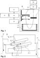
- FIG 1 is a schematic representation of an apparatus for mass analysis of ions. It does not form an embodiment of the present invention, the apparatus is described in order to help understanding the invention, an embodiment of which being described below, in connection with Figures 6 and 7 .
- a high current ion source 10 such as an electron impact ion sources generates an ion beam.
- the output of the ion source 10 is about 50 million ions/s.
- the ion source is coupled to a mass filter 20 comprising an RF-only quadrupole ion guide 30, as displayed in Figure 2 .
- the quadrupole ion guide 30 comprises four rods 31.1...31.4 arranged parallel to each other, the intersections of the rods 31.1...31.4 with a plane perpendicular to the rods 31.1...31.4 constituting a square.
- the RF quadrupole 30 is used for elimination of ions belonging to narrow bands of m/q. It is known that an oscillatory inhomogeneous electrical field forms a so-called effective potential which is proportional to E 2 , where E is the amplitude of the electrical field strength oscillations.
- the invention consists of a primary RF-only quadrupole field capable of transmitting the mass range of interest.
- One or several additional RF frequencies with smaller amplitudes are superimposed onto the primary RF field.
- the frequencies of those additional RF fields must be adjusted to the characteristic oscillation frequencies of the ions to be removed in the primary RF field. Due to these resonant excitations, these ions are then gradually excited by the low amplitude RF fields until they gain enough radial energy to leave the primary RF field. Thereby, these ions are eliminated from entering the following mass analyzer, time-of-flight mass spectrometer (TOFMS) 40.
- TOFMS time-of-flight mass spectrometer
- the TOFMS 40 receives all remaining ions.
- the ions are orthogonally extracted from the primary ion beam into the TOFMS 40. Accelerated by grids 42 the ions traverse the TOFMS 40, passing a reflector 43, and finally hit a detector 44.
- the detector 44 is connected to data acquisition system 50, which in turn is connected to a computer 60 for further processing of the data.
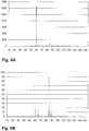
- the Figures 3A, 3B demonstrate the effect of mass filtering on a mass spectrum obtained using a downstream TOFMS.
- the spectrum of the ions provided by the high current ion source includes a major ion species, i. e. an ion species of high abundance, having a m/q of about 73 Th. In the given example, about 60% of the detected ions belong to this major species.
- the large number of ions delivered to the TOF-MS lead to saturation of the ion detector and/or the detection electronics. Both these effects as well as peak tails caused by the major species lead to errors in the measurements as well as decreased statistics leading to higher measurement uncertainties.
- FIG 3B the spectrum as measured by the TOFMS arranged downstream of a mass filter according to the invention is displayed.
- the peak at about 73 Th representing the remaining ions measured by the TOFMS is substantially decreased to about 2 % of the effective number of ions generated by the high current ion source. Due to this substantial decrease the further ions of different m/q may be more accurately measured and saturation of the ion detector and/or the detection electronics (data acquisition) is avoided.
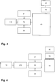
- Figure 4 is a schematic representation of a second apparatus for mass analysis of ions comprising a selective ion source. Again, it does not form an embodiment of the present invention, the apparatus is described in order to help understanding the invention, an embodiment of which being described below, in connection with Figures 6 and 7 . In many aspects, the apparatus displayed in Figure 4 corresponds to the apparatus described above in connection with Figure 1 . However, instead of the (broad-band) high current ion source a selective ion source 110 is employed. In the selective ionization process carried out within the ion source 110 primary ions are created that subsequently transfer charge to secondary particles to be ionized.
- the measured spectrum resembles to the spectrum displayed in Figure 5A .
- the primary ions having a mass/charge of 60 Th in the displayed example dominate the mass spectrum.
- the large number of ions delivered to the TOF-MS lead to saturation of the ion detector and/or the detection electronics. Both these effects as well as peak tails caused by the major species lead to increased noise interfering with the measurements as well as decreased statistics leading to higher measurement uncertainties.
- the mass filter 20 Using the mass filter 20 a large percentage of the primary ions may be filtered out before they reach the time-of-flight mass spectrometer (TOFMS) 40.
- TOFMS time-of-flight mass spectrometer
- the main RF source 21 as well as the excitation RF source 22 are controlled such that RF voltages are generated that lead to elimination of ions having a mass of 60.
- the TOFMS 40 as well as the data acquisition system 50 and the computer 60 are relieved from analyzing the vast majority of (artifact) ions generated by the selective ion source 110.
- the corresponding spectrum measured by the TOFMS 40 is displayed in Figure 5B .
- FIG. 6 An inventive apparatus for mass analysis of ions is displayed in Figure 6 . Again, in many aspects this apparatus corresponds to the apparatus described above in connection with Figure 1 . However, a device 270 for cooling the ions generated by the high-current ion source 10 is coupled between the ion source 10 and the mass filter 20.
- the device 270 comprises an RF quadrupole ion guide generating a confining quadrupole field capable of transmitting the supplied ions. It holds a gaseous atmosphere filling at least the confining region of the quadrupole field. The pressure of the gaseous atmosphere is about 10 Pa, whereas the same gas is used as in the upstream ion source 10.
- the ions supplied to the device 270 are cooled and thereby an ideal ion phase space is created that allows for substantially lossless injection of the ions into the mass filter 20 as well as transport of the ions through the mass filter 20.
- the modified phase space provides for an optimum filtering efficiency within the mass filter 20 as well as for improved quality of the measurements taken at the TOFMS 40.
- the device 270 facilitates the transition of the produced ions from the high pressure ion source 10 to the low pressure mass filter 20 / TOFMS 40.
- Figure 7 shows a mass spectrum from a high current ion source recorded without filter (grey line 71). Multiple saturation effects are visible: peak distortions due to DAQ saturation and reflected signals, high background, peak tails. Another mass spectrum of the same source is recorded while filtering the two abundant species at 40 and 41 Th (full line 72). The background is now greatly reduced and the Signal-to-noise ratio of neighboring species is now enhanced up to several orders of magnitude.
- RF-only 2-dimensional quadrupole trapping field other fields may be used such as 3-dimensional fields, higher multipole fields and/or rotating fields.
- an additional DC voltage may be used on the quadrupole rods.
- the shaping of the RF electrodes may be varied as well, depending on the desired characteristics of the multipole field to be created.
- the invention creates an apparatus for mass analysis that allows for analyzing minor compound ions generated by a high current ion source with good selectivity, undisturbed by major compounds.
Landscapes
- Chemical & Material Sciences (AREA)
- Analytical Chemistry (AREA)
- Other Investigation Or Analysis Of Materials By Electrical Means (AREA)
- Electron Tubes For Measurement (AREA)
Claims (18)
- Vorrichtung zur Massenanalyse von Ionen, umfassend:a) eine Ionenquelle (10);b) ein Flugzeitmassenspektrometer (40) zur Analyse von Ionen, die von der Ionenquelle (10) übertragen werden;c) ein Filter (20) zum Segmentieren eingehender Ionen entsprechend ihrem Masse-zu-Ladung-Verhältnis in eine erste Gruppe von Ionen und in eine zweite Gruppe von Ionen, wobei das Filter (20) an die Ionenquelle (10) gekoppelt ist und wobei das Filter (20) und das Flugzeitmassenspektrometer derart angeordnet sind, dass die Ionen der ersten Gruppe zum Massenspektrometer (40) gesendet werden und dass die Ionen der zweiten Gruppe nicht zum Massenspektrometer (40) gesendet werden;wobeid) das Filter (20) derart konzipiert ist, dass die zweite Gruppe aus Ionen besteht, die zu einem schmalen Band oder mehreren schmalen Bändern von Masse zu Ladung gehören;e) das Filter (20) eine felderzeugende Einrichtung (21, 22, 30, 31.1...31.4) umfasst, die derart konzipiert ist, dass sie ein primäres einschließendes Feld erzeugt, das Ionen zum Flugzeitmassenspektrometer übertragen kann, sowie ein oder mehrere dem primären Feld überlagerte HF-Felder;dadurch gekennzeichnet, dassf) Frequenzen der überlagerten HF-Felder Oszillationsfrequenzen von Ionen entsprechen, die zu dem einen schmalen Band oder den mehreren schmalen Bändern von Masse zu Ladung gehören, so dass diese Ionen resonant angeregt und schließlich aus einem einschließenden Bereich des primären Felds ausgestoßen werden;g) die Ionenquelle (10) eine Hochstrom-Ionenquelle ist, insbesondere eine Ionenquelle, die an einem Ausgang der Ionenquelle mindestens 5 Millionen Ionen/s, vorzugsweise mindestens 50 Millionen Ionen/s, bereitstellt;h) die Ionenquelle sowie das Flugzeitmassenspektrometer derart eingerichtet sind und betrieben werden, dass ein durch die Ionenquelle (10) erzeugter Ionenfluss Sättigungseffekte im Flugzeitmassenspektrometer (40) hervorruft, wenn die Ionenquelle (10) direkt mit dem Flugzeitmassenspektrometer (40) gekoppelt ist; und dassi) die Vorrichtung eine Einrichtung (270) zum Kühlen der in das Filter (20) einzuführenden Ionen umfasst, wobei die Einrichtung (270) derart konzipiert ist, dass sie ein einschließendes Multipolfeld erzeugt, das Ionen zu dem Filter (20) übertragen kann, und dass sie eine gashaltige Atmosphäre aufweist, die eine einschließende Region des Multipolfelds füllt.
- Vorrichtung nach Anspruch 1, dadurch gekennzeichnet, dass das Flugzeitmassenspektrometer (40) ein ADC-Ionendetektionssystem umfasst.
- Vorrichtung nach Anspruch 1 oder 2, dadurch gekennzeichnet, dass das primäre einschließende Feld ein HF-Multipolfeld ist.
- Vorrichtung nach Anspruch 3, dadurch gekennzeichnet, dass das primäre einschließende Feld ein Nur-HF-Quadrupolfeld ist.
- Vorrichtung nach Anspruch 4, dadurch gekennzeichnet, dass das Quadrupolfeld zweidimensional ist und die Ionen in einem Bereich einbehält, der ihren Hauptpfad zu dem Flugzeitmassenspektrometer umgibt.
- Vorrichtung nach Anspruch 5, dadurch gekennzeichnet, dass die felderzeugende Einrichtung ein rotierendes Quadrupolfeld erzeugen kann.
- Vorrichtung nach einem der Ansprüche 1 bis 6, dadurch gekennzeichnet, dass die felderzeugende Einrichtung ferner ein dem primären Feld überlagertes koaxiales lineares Feld erzeugt, um die eingehenden Ionen entlang einer Achse des primären Felds zu transportieren.
- Vorrichtung nach einem der Ansprüche 1 bis 7, dadurch gekennzeichnet, dass die felderzeugende Einrichtung derart konzipiert ist, dass unterschiedliche überlagerte HF-Frequenzen abwechselnd erzeugt werden können, so dass mehrere schmale Bänder von Masse zu Ladung abgetastet werden und zu diesen Bändern gehörende Ionen resonant angeregt und aus dem einschließenden Bereich des primären Felds ausgestoßen werden.
- Vorrichtung nach einem der Ansprüche 1 bis 8, dadurch gekennzeichnet, dass die felderzeugende Einrichtung derart konzipiert ist, dass überlagerte HF-Frequenzen erzeugt werden können, die mit einer auswählbaren Pulsbreite pulsieren, um eine Ionenzahl von mindestens einem der schmalen Bänder von Masse zu Ladung selektiv zu reduzieren oder um anschließend unterschiedliche Massenspektren durch das Flugzeitmassenspektrometer zu analysieren.
- Vorrichtung nach einem der Ansprüche 1 bis 9, dadurch gekennzeichnet, dass die felderzeugende Einrichtung derart konzipiert ist, dass HF-Felder erzeugt werden können, die Ionen der zweiten Gruppe um einen Faktor pI unterdrücken, wobei insbesondere 10-4<pI<0,1 gilt.
- Vorrichtung nach einem der Ansprüche 1 bis 10, dadurch gekennzeichnet, dass die Hochstrom-Ionenquelle eine selektive Ionenquelle (110) zum selektiven Ionisieren von zu analysierenden Partikeln ist und dass die selektiv ionisierten Partikel zu dem Flugzeitmassenspektrometer (40) übertragen werden.
- Verfahren zur Massenanalyse von Ionen unter Verwendung einer Ionenquelle sowie eines Flugzeitmassenspektrometers, umfassend die Schritte:a) Segmentieren eingehender Ionen entsprechend ihrem Masse-zu-Ladung-Verhältnis in eine erste Gruppe von Ionen und in eine zweite Gruppe von Ionen;b) Übertragen der Ionen der ersten Gruppe zu dem Flugzeitmassenspektrometer und Verwerfen der Ionen der zweiten Gruppe;wobeic) die eingehenden Ionen derart segmentiert werden, dass die zweite Gruppe von Ionen aus Ionen besteht, die zu einem oder mehreren schmalen Bändern von Masse zu Ladung gehören; undd) die eingehenden Ionen zum Segmentieren in ein primäres einschließendes Feld injiziert werden, das Ionen zu dem Flugzeitmassenspektrometer übertragen kann und von einer oder mehreren HF-Frequenzen überlagert wird,dadurch gekennzeichnet, dass die Ionenquelle sowie das Flugzeitmassenspektrometer derart eingerichtet sind und betrieben werden, dass ein durch die Ionenquelle erzeugter Ionenfluss Sättigungseffekte im Flugzeitmassenspektrometer hervorrufen würde, falls die Ionenquelle direkt mit dem Flugzeitmassenspektrometer gekoppelt wäre; da
die überlagerten HF-Frequenzen derart gewählt sind, dass sie Oszillationsfrequenzen von Ionen entsprechen, die zu dem einen schmalen Band oder den mehreren schmalen Bändern von Masse zu Ladung gehören, so dass diese Ionen resonant angeregt und schließlich aus einem einschließenden Bereich des primären Felds ausgestoßen werden; und da
die Ionen vor dem Segmentierungsschritt durch Injizieren der Ionen in eine gashaltige Atmosphäre gekühlt werden und die Ionen gleichzeitig einem einschließenden Multipolfeld ausgesetzt werden, das Ionen zu dem Filter übertragen kann. - Verfahren nach Anspruch 12, dadurch gekennzeichnet, dass die Ionen während des Segmentierungsschritts einem dem primären Feld überlagerten koaxialen linearen Feld ausgesetzt werden, um entlang einer Achse des primären Feldes zu dem Flugzeitmassenspektrometer transportiert zu werden.
- Verfahren nach Anspruch 12 oder 13, dadurch gekennzeichnet, dass unterschiedliche überlagerte HF-Frequenzen abwechselnd erzeugt werden, sodass mehrere schmale Bänder von Masse zu Ladung abgetastet werden und zu diesen Bändern gehörende Ionen resonant angeregt und aus dem einschließenden Bereich des primären Feldes ausgestoßen werden.
- Verfahren nach einem der Ansprüche 12 bis 14, dadurch gekennzeichnet, dass überlagerte HF-Frequenzen erzeugt werden, die mit einer auswählbaren Pulsbreite pulsieren, um eine Ionenzahl von mindestens einem der schmalen Bänder von Masse zu Ladung selektiv zu reduzieren oder um anschließend unterschiedliche Massenspektren durch das Flugzeitmassenspektrometer zu analysieren.
- Verfahren zur Massenanalyse von Partikeln, umfassend den Schritt des selektiven Ionisierens von zu analysierenden Partikeln sowie das Verfahren nach einem der Ansprüche 12 bis 15 zur Massenanalyse der selektiv ionisierten Partikel.
- Verfahren nach einem der Ansprüche 12 bis 16, dadurch gekennzeichnet, dass die Ionen in einem einschließenden Multipolfeld gespeichert werden und die HF-Ausstoßfrequenzen während einer gesamten Speicherzeit der Ionen oder eines Teils davon beaufschlagt werden.
- Verfahren nach einem der Ansprüche 12 bis 17, dadurch gekennzeichnet, dass die Segmentierung der eingehenden Ionen derart erfolgt, dass die Ionen der zweiten Gruppe um einen Faktor pI unterdrückt werden, wobei insbesondere 10-5<pI<0,1 gilt und wobei das Verfahren einen Kalibrierungsschritt aufweist, bei dem der Faktor pI bewertet wird, um eine Ausbeute von Ionen in der zweiten Gruppe quantitativ zu analysieren.
Priority Applications (1)
| Application Number | Priority Date | Filing Date | Title |
|---|---|---|---|
| EP07405338.0A EP1933366B1 (de) | 2006-12-14 | 2007-11-28 | Vorrichtung zur Massenanalyse von Ionen |
Applications Claiming Priority (2)
| Application Number | Priority Date | Filing Date | Title |
|---|---|---|---|
| EP06405519A EP1933365A1 (de) | 2006-12-14 | 2006-12-14 | Vorrichtung zur Massenanalyse von Ionen |
| EP07405338.0A EP1933366B1 (de) | 2006-12-14 | 2007-11-28 | Vorrichtung zur Massenanalyse von Ionen |
Publications (2)
| Publication Number | Publication Date |
|---|---|
| EP1933366A1 EP1933366A1 (de) | 2008-06-18 |
| EP1933366B1 true EP1933366B1 (de) | 2019-06-12 |
Family
ID=39399063
Family Applications (1)
| Application Number | Title | Priority Date | Filing Date |
|---|---|---|---|
| EP07405338.0A Active EP1933366B1 (de) | 2006-12-14 | 2007-11-28 | Vorrichtung zur Massenanalyse von Ionen |
Country Status (1)
| Country | Link |
|---|---|
| EP (1) | EP1933366B1 (de) |
Families Citing this family (14)
| Publication number | Priority date | Publication date | Assignee | Title |
|---|---|---|---|---|
| EP1968100B1 (de) | 2007-03-08 | 2014-04-30 | Tofwerk AG | Ionenführungskammer |
| GB201104292D0 (en) * | 2011-03-15 | 2011-04-27 | Micromass Ltd | M/z targets attenuation on time of flight instruments |
| GB201118579D0 (en) * | 2011-10-27 | 2011-12-07 | Micromass Ltd | Control of ion populations |
| GB201516057D0 (en) * | 2015-09-10 | 2015-10-28 | Q Tek D O O | Resonance mass separator |
| WO2019229469A1 (en) | 2018-05-31 | 2019-12-05 | Micromass Uk Limited | Mass spectrometer |
| GB201808894D0 (en) | 2018-05-31 | 2018-07-18 | Micromass Ltd | Mass spectrometer |
| GB201808932D0 (en) | 2018-05-31 | 2018-07-18 | Micromass Ltd | Bench-top time of flight mass spectrometer |
| GB201808949D0 (en) | 2018-05-31 | 2018-07-18 | Micromass Ltd | Bench-top time of flight mass spectrometer |
| GB201808893D0 (en) | 2018-05-31 | 2018-07-18 | Micromass Ltd | Bench-top time of flight mass spectrometer |
| GB201808892D0 (en) | 2018-05-31 | 2018-07-18 | Micromass Ltd | Mass spectrometer |
| GB201808890D0 (en) | 2018-05-31 | 2018-07-18 | Micromass Ltd | Bench-top time of flight mass spectrometer |
| GB201808936D0 (en) | 2018-05-31 | 2018-07-18 | Micromass Ltd | Bench-top time of flight mass spectrometer |
| GB201808912D0 (en) | 2018-05-31 | 2018-07-18 | Micromass Ltd | Bench-top time of flight mass spectrometer |
| US11373849B2 (en) | 2018-05-31 | 2022-06-28 | Micromass Uk Limited | Mass spectrometer having fragmentation region |
Citations (2)
| Publication number | Priority date | Publication date | Assignee | Title |
|---|---|---|---|---|
| US6621074B1 (en) * | 2002-07-18 | 2003-09-16 | Perseptive Biosystems, Inc. | Tandem time-of-flight mass spectrometer with improved performance for determining molecular structure |
| EP1522087A1 (de) * | 2002-07-16 | 2005-04-13 | Leco Corporation | Tandem fluzeitmassenspektrometer und verfahren |
Family Cites Families (8)
| Publication number | Priority date | Publication date | Assignee | Title |
|---|---|---|---|---|
| US5248882A (en) * | 1992-05-28 | 1993-09-28 | Extrel Ftms, Inc. | Method and apparatus for providing tailored excitation as in Fourier transform mass spectrometry |
| EP0871201B1 (de) * | 1995-07-03 | 2010-09-15 | Hitachi, Ltd. | Massenspektrometer |
| US5598001A (en) * | 1996-01-30 | 1997-01-28 | Hewlett-Packard Company | Mass selective multinotch filter with orthogonal excision fields |
| US6140638A (en) | 1997-06-04 | 2000-10-31 | Mds Inc. | Bandpass reactive collision cell |
| GB0000528D0 (en) | 2000-01-11 | 2000-03-01 | Nokia Networks Oy | Location of a station in a telecommunications system |
| US6586727B2 (en) * | 2000-06-09 | 2003-07-01 | Micromass Limited | Methods and apparatus for mass spectrometry |
| US6627912B2 (en) | 2001-05-14 | 2003-09-30 | Mds Inc. | Method of operating a mass spectrometer to suppress unwanted ions |
| US6900431B2 (en) | 2003-03-21 | 2005-05-31 | Predicant Biosciences, Inc. | Multiplexed orthogonal time-of-flight mass spectrometer |
-
2007
- 2007-11-28 EP EP07405338.0A patent/EP1933366B1/de active Active
Patent Citations (2)
| Publication number | Priority date | Publication date | Assignee | Title |
|---|---|---|---|---|
| EP1522087A1 (de) * | 2002-07-16 | 2005-04-13 | Leco Corporation | Tandem fluzeitmassenspektrometer und verfahren |
| US6621074B1 (en) * | 2002-07-18 | 2003-09-16 | Perseptive Biosystems, Inc. | Tandem time-of-flight mass spectrometer with improved performance for determining molecular structure |
Also Published As
| Publication number | Publication date |
|---|---|
| EP1933366A1 (de) | 2008-06-18 |
Similar Documents
| Publication | Publication Date | Title |
|---|---|---|
| EP1933366B1 (de) | Vorrichtung zur Massenanalyse von Ionen | |
| US20080149825A1 (en) | Apparatus for mass analysis of ions | |
| EP2385543B1 (de) | Steuerung von Ionenpopulation in einem Massenanalysegerät | |
| US10510525B2 (en) | Ion beam mass pre-separator | |
| US10224193B2 (en) | Method of tandem mass spectrometry | |
| US10410847B2 (en) | Targeted mass analysis | |
| EP1135790B1 (de) | Verfahren und vorrichtung zur anwendung in der tandemmassenspektrometrie | |
| CA2312754C (en) | Method of and apparatus for selective collision-induced dissociation of ions in a quadrupole ion guide | |
| US8637816B1 (en) | Systems and methods for MS-MS-analysis | |
| US20110204221A1 (en) | Mass spectrometer and method of mass spectrometry | |
| EP2309531A1 (de) | Massenanalysator | |
| US8927928B2 (en) | Method for operating a time-of-flight mass spectrometer with orthogonal ion pulsing | |
| CN113948365B (zh) | 一种复合式质谱仪 | |
| Ens et al. | Hybrid quadrupole/time‐of‐flight mass spectrometers for analysis of biomolecules | |
| GB2489093A (en) | Pre-scan for mass to charge ratio range | |
| EP4141909A2 (de) | Erweiterung des dynamischen bereichs | |
| CN108140535B (zh) | 具有轴向场的碰撞池 | |
| WO2005114703A2 (en) | Tandem-in-time and tandem-in-space mass and ion mobility spectrometer and method | |
| EP3916755A1 (de) | Verfahren und vorrichtung für hochgeschwindigkeitsmassenspektrometrie | |
| Amad et al. | Mass resolution of 11,000 to 22,000 with a multiple pass quadrupole mass analyzer | |
| CA2396925A1 (en) | An apparatus for and method of discriminating against unwanted ionized species in mass spectrometry with collision and reaction devices | |
| US8324566B2 (en) | Isolation of ions in overloaded RF ion traps |
Legal Events
| Date | Code | Title | Description |
|---|---|---|---|
| PUAI | Public reference made under article 153(3) epc to a published international application that has entered the european phase |
Free format text: ORIGINAL CODE: 0009012 |
|
| AK | Designated contracting states |
Kind code of ref document: A1 Designated state(s): AT BE BG CH CY CZ DE DK EE ES FI FR GB GR HU IE IS IT LI LT LU LV MC MT NL PL PT RO SE SI SK TR |
|
| AX | Request for extension of the european patent |
Extension state: AL BA HR MK RS |
|
| AKX | Designation fees paid | ||
| 17P | Request for examination filed |
Effective date: 20081210 |
|
| RBV | Designated contracting states (corrected) |
Designated state(s): CH DE FR GB LI |
|
| 17Q | First examination report despatched |
Effective date: 20141112 |
|
| RAP1 | Party data changed (applicant data changed or rights of an application transferred) |
Owner name: TOFWERK AG |
|
| STAA | Information on the status of an ep patent application or granted ep patent |
Free format text: STATUS: EXAMINATION IS IN PROGRESS |
|
| GRAP | Despatch of communication of intention to grant a patent |
Free format text: ORIGINAL CODE: EPIDOSNIGR1 |
|
| STAA | Information on the status of an ep patent application or granted ep patent |
Free format text: STATUS: GRANT OF PATENT IS INTENDED |
|
| INTG | Intention to grant announced |
Effective date: 20190103 |
|
| GRAS | Grant fee paid |
Free format text: ORIGINAL CODE: EPIDOSNIGR3 |
|
| GRAA | (expected) grant |
Free format text: ORIGINAL CODE: 0009210 |
|
| STAA | Information on the status of an ep patent application or granted ep patent |
Free format text: STATUS: THE PATENT HAS BEEN GRANTED |
|
| AK | Designated contracting states |
Kind code of ref document: B1 Designated state(s): CH DE FR GB LI |
|
| REG | Reference to a national code |
Ref country code: GB Ref legal event code: FG4D |
|
| REG | Reference to a national code |
Ref country code: CH Ref legal event code: EP |
|
| REG | Reference to a national code |
Ref country code: DE Ref legal event code: R096 Ref document number: 602007058562 Country of ref document: DE |
|
| REG | Reference to a national code |
Ref country code: CH Ref legal event code: NV Representative=s name: KELLER AND PARTNER PATENTANWAELTE AG, CH |
|
| REG | Reference to a national code |
Ref country code: DE Ref legal event code: R097 Ref document number: 602007058562 Country of ref document: DE |
|
| PLBE | No opposition filed within time limit |
Free format text: ORIGINAL CODE: 0009261 |
|
| STAA | Information on the status of an ep patent application or granted ep patent |
Free format text: STATUS: NO OPPOSITION FILED WITHIN TIME LIMIT |
|
| 26N | No opposition filed |
Effective date: 20200313 |
|
| REG | Reference to a national code |
Ref country code: DE Ref legal event code: R082 Ref document number: 602007058562 Country of ref document: DE Representative=s name: K & P PATENTANWALTSGESELLSCHAFT MBH, DE |
|
| REG | Reference to a national code |
Ref country code: CH Ref legal event code: PFA Owner name: TOFWERK AG, CH Free format text: FORMER OWNER: TOFWERK AG, CH |
|
| REG | Reference to a national code |
Ref country code: CH Ref legal event code: U11 Free format text: ST27 STATUS EVENT CODE: U-0-0-U10-U11 (AS PROVIDED BY THE NATIONAL OFFICE) Effective date: 20251201 |
|
| PGFP | Annual fee paid to national office [announced via postgrant information from national office to epo] |
Ref country code: DE Payment date: 20251205 Year of fee payment: 19 |
|
| PGFP | Annual fee paid to national office [announced via postgrant information from national office to epo] |
Ref country code: GB Payment date: 20251127 Year of fee payment: 19 |
|
| PGFP | Annual fee paid to national office [announced via postgrant information from national office to epo] |
Ref country code: FR Payment date: 20251127 Year of fee payment: 19 |
|
| PGFP | Annual fee paid to national office [announced via postgrant information from national office to epo] |
Ref country code: CH Payment date: 20251201 Year of fee payment: 19 |