EP1933112B1 - Verbesserte Vorrichtung und Verfahren zur Umgehung der Totzone bei einem faseroptischen Gyroskop - Google Patents
Verbesserte Vorrichtung und Verfahren zur Umgehung der Totzone bei einem faseroptischen Gyroskop Download PDFInfo
- Publication number
- EP1933112B1 EP1933112B1 EP07254765A EP07254765A EP1933112B1 EP 1933112 B1 EP1933112 B1 EP 1933112B1 EP 07254765 A EP07254765 A EP 07254765A EP 07254765 A EP07254765 A EP 07254765A EP 1933112 B1 EP1933112 B1 EP 1933112B1
- Authority
- EP
- European Patent Office
- Prior art keywords
- dither
- signal
- pilot
- output
- loop
- Prior art date
- Legal status (The legal status is an assumption and is not a legal conclusion. Google has not performed a legal analysis and makes no representation as to the accuracy of the status listed.)
- Active
Links
- 239000000835 fiber Substances 0.000 title claims description 58
- 238000000034 method Methods 0.000 title claims description 24
- 238000005070 sampling Methods 0.000 claims description 15
- 230000003111 delayed effect Effects 0.000 claims description 13
- 230000003068 static effect Effects 0.000 claims description 8
- 238000010586 diagram Methods 0.000 description 3
- 230000003287 optical effect Effects 0.000 description 2
- 238000005295 random walk Methods 0.000 description 2
- 230000003247 decreasing effect Effects 0.000 description 1
- 238000006073 displacement reaction Methods 0.000 description 1
- 230000000737 periodic effect Effects 0.000 description 1
Images

Classifications
-
- G—PHYSICS
- G01—MEASURING; TESTING
- G01C—MEASURING DISTANCES, LEVELS OR BEARINGS; SURVEYING; NAVIGATION; GYROSCOPIC INSTRUMENTS; PHOTOGRAMMETRY OR VIDEOGRAMMETRY
- G01C19/00—Gyroscopes; Turn-sensitive devices using vibrating masses; Turn-sensitive devices without moving masses; Measuring angular rate using gyroscopic effects
- G01C19/58—Turn-sensitive devices without moving masses
- G01C19/64—Gyrometers using the Sagnac effect, i.e. rotation-induced shifts between counter-rotating electromagnetic beams
- G01C19/72—Gyrometers using the Sagnac effect, i.e. rotation-induced shifts between counter-rotating electromagnetic beams with counter-rotating light beams in a passive ring, e.g. fibre laser gyrometers
- G01C19/721—Details, e.g. optical or electronical details
Definitions
- This invention relates generally to fiber optic gyroscope rotation sensing systems. More particularly, this invention relates to the processing of signals output from a fiber optic gyroscope to measure rotation rates. Still more particularly, this invention relates to an improved dither system and method using a low amplitude dither signal in a fiber optic gyroscope signal processing system.
- U. S. Patent No. 5,020,912 which issued June 4, 1991 to George A. Pavlath, one of the inventors of the present invention, discloses a deadband circumvention technique for a closed loop fiber gyro that uses deterministic phase modulation.
- a periodic zero mean dither signal is input to an integrator that also has the gyro demodulated rate signal as an input.
- a key requirement is that the gyro loop bandwidth be greater than the dither frequency, which in turn is larger than the sampling frequency.
- the dither frequency is at least ten times the sampling frequency
- the loop bandwidth is at least ten times the dither frequency. If these conditions are not met, problems occur in operation of the fiber optic gyro as a rotation sensor.
- the problems include saturation of the front end of the gyro control loop for large dither amplitudes due to the limited loop bandwidth and finite analog to digital converter input range and large dither residuals in the output if there are not precisely an integer number of dither cycles in the sampling period. Saturation in the control loop leads to increased random walk through failure to cancel the dither signal and other undesirable nonlinearities. Decreasing the amplitude of the dither signal to avoid saturation could result in there not being sufficient dither to break up the deadband at high sampling rates. Applying a small amplitude dither signal for a time longer than the sampling time causes each sample to include a large amount of residual dither.
- US Patent No. 5,949,545 discloses a fiber optic gyroscope which uses a dither signal, and enables an output signal to be taken over any time interval by sampling the gyroscope's feedback signal.
- US Patent No. 4,132,482 describes a ring laser gyroscope including an open loop dither system.
- a dynamic feedback system is provided between the ring laser gyroscope output and dither rate input to minimize the residual "lock-in" which usually remains with an open loop dither system.
- US Patent No. 6,476,918 describes a laser gyroscope with a dither control system.
- the dither control system includes a dither motor for dithering the laser gyroscope through a desired angular displacement.
- the present invention provides a method for circumventing a deadband in signals output from a fiber optic gyroscope as claimed in Claim 1.
- the present invention also provides apparatus for circumventing a deadband in signals output from a fiber optic gyroscope as claimed in Claim 9.
- the dither system and method permits application of a low amplitude dither signal for many sampling periods without increasing the noise in the sampled outputs due to residual dither signals.
- the advantages of the invention over the prior art are achieved by adding a dither loop and an accumulator to the signal processing system of fiber optic gyroscope rotation sensing system.
- the dither loop has a delay and a gain that are adjusted to match the gain and delay of the fiber gyro loop.
- a zero mean dither of amplitude sufficient to break up the deadband is injected into to gyro and the dither loop.
- the dither loop filters the dither signal iu the same manner as the gyro loop to provide a signal that is input to a differencing circuit to remove the dither signal from the gyro output.
- a method for circumventing a deadband in signals output from a fiber optic gyroscope comprises the steps of providing a fiber optic gyroscope loop that includes signal processing apparatus connected between an input and an output of the fiber optic gyroscope and injecting a dither signal into the signal processing apparatus so that the dither signal is added to signals output from the fiber optic gyroscope.
- the method further includes integrating the sum of the dither signal and the signals output from the fiber optic gyroscope with an integrator to produce a gyro output plus dither signal.
- the dither signal is injected into a dither loop that is arranged to provide a filtered dither signal that is filtered in the same manner that the fiber optic gyroscope loop filters the dither signal input thereto.
- the gyro output plus dither signal output from the fiber optic gyroscope and the filtered dither signal output from the dither loop are input to a differencing apparatus to provide a gyro signal output that includes no dither signal.
- the method preferably comprises the step of adjusting the gain of the dither loop to equal the gain of the fiber optic gyroscope loop so that the signal output from the dither loop has an amplitude that is the same as the amplitude of the dither signal component of the signal output from the fiber optic gyroscope loop.
- the method preferably also further comprises the steps of accumulating the gyro output plus dither signal from the integrator with a gyro accumulator and accumulating the filtered dither signal output from the dither loop with a dither accumulator.
- the gyro accumulator and the dither accumulator are sampled simultaneously and their outputs are input to the differencing apparatus to produce the gyro signal output.
- the method may further comprise the steps of forming the dither loop to include a dither summing circuit arranged to receive the dither signal as an input, connecting an output of the dither summing circuit to a dither integrator, and connecting a dither delay circuit to the dither integrator to receive a signal output therefrom and to produce a delayed dither signal.
- the delayed dither signal is amplified and input to a dither multiplier that multiplies the amplified dither signal by a fine gain adjust signal.
- the dither multiplier is connected to the dither summing circuit so that signals output from the dither multiplier are added to the dither signal.
- the method according to the present invention preferably further comprises the step of providing a pilot signal that is input to the dither loop so that the dither loop produces a dither plus pilot signal output and so that the fiber optic gyroscope loop produces gyro plurality dither plus pilot signal output
- the method according to the present invention also preferably further comprises the steps of combining the gyro plus dither plus pilot signal output from the fiber optic gyroscope loop with the dither plus pilot signal in a differencing circuit to produce a gyro plus residual dither plus residual pilot signal output, and processing the pilot signal and the gyro plus residual dither plus residual pilot signal with a gain adjust loop arranged to provide a fine gain adjust signal that is input to both the dither loop and the pilot loop to adjust the gains thereof so that the residual dither signal and the residual pilot signal have zero amplitude so that the differencing circuit output is the gyro output without any dither or pilot signal component.
- the method may further comprise the steps of forming the pilot loop to include a pilot summing circuit arranged to receive the pilot signal as an input, connecting an output of the pilot summing circuit to a pilot integrator, and connecting a pilot delay circuit to the pilot integrator to receive a signal output therefrom and to produce a delayed pilot signal.
- the delayed pilot signal is amplified and then input to a pilot multiplier that multiplies the amplified pilot signal by the fine gain adjust signal output from the gain adjust loop.
- the pilot multiplier is connected to the pilot summing circuit so that signals output from the pilot multiplier are added to the pilot signal.
- the method may also further comprise the steps of multiplying a filtered gyro plus residual dither plus residual pilot signal by a filteral a signal output from the pilot integrator with a multiplier circuit and amplifying signals output from the multiplier with a variable gain amplifier.
- Signals output from the variable gain amplifier are integrated with a gain adjust integrator to produce an output that is amplified by a static gain amplifier.
- Signals output from the static gain amplifier are sampled with a sampling circuit to produce again error signal that is differenced from unity to obtain the fine gain adjust signal.
- FIG. 1 is a block diagram of a first embodiment of the invention.
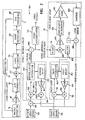
- FIG. 2 is block diagram of an enhanced second embodiment of the invention.
- a fiber optic rotation sensing system 10 includes a fiber gyro loop 11 that includes a fiber optic gyroscope 12 arranged to provide an optical signal to a photodetector 14.
- the photodetector 14 forms an electrical signal that corresponds to the optical signal input thererto.
- An amplifier 16 amplifies the electrical signal output from the photodetector 14 and inputs the amplified electrical signal into an analog to digital converter 18, which converts the analog output of the fiber optic gyroscope 12 into a corresponding digital signal.
- the digitized signal is input to a summer 20.
- a dither circuit 22 provides a dither signal to the summer 20.
- the summer 20 sums the digitized gyro output and the dither signal and input thereto and inputs a sum signal into a gyro integrator 24.
- the output of the gyro integrator 24 is input to both a ramp generator 26 and a gyro accumulator 28.
- the output of the ramp generator 26 is input to a digital to analog circuit 29 that is connected to the fiber gyro 12 so that the fiber gyro 12 receives a dithered ramp signal input.
- the dither signal from the dither circuit 22 is also input to a summer 30 that is included in a dither loop 32.
- Signal output from the summer 30 are input to a dither integrator 34.
- the dither integrator 34 has an output that is connected to a delay circuit 36 in the dither loop 32.
- the delay circuit 36 is connected to an amplifier 38, which provides an amplified signal to a multiplier 40 that also receives a fine gain adjust signal from a fine gain circuit 42.
- the output of the dither integrator 34 is also input to a dither accumulator 44.
- Signals output from the gyro accumulator 28 and the dither accumulator 44 are input to a differencing circuit 46.
- the delay and gain of the dither loop 32 are adjusted to match the delay and gain of the fiber gyro loop 11.
- the dither circuit 22 provides a zero mean dither signal of amplitude sufficient to break up the deadband.
- the zero mean dither signal is injected into the gyro loop 11 at the summer 20, which is connected to the input of the gyro integrator 24.
- the zero mean dither signal is input to the dither loop 32 at the summer 30, which is connected to the input of the dither integrator 34.
- the function of the dither loop 32 is to filter the dither signal in essentially the same manner that the gyro loop 11 filters the dither signal to permit removal of the dither signal from the gyro output.
- the output of the gyro integrator 24 is fed into the gyro accumulator 28, which is sampled and cleared at the gyro output frequency.
- the signal output of the resetting accumulator 28 contains the desired gyro output signal summed with the dither signal that has been tittered by its traversal of the gyro loop 11.
- the output of the dither integrator 34 is sent to the dither accumulator 44, which is sampled and reset at the same time as the gyro accumulator 28.
- the output of the dither accumulator 34 contains only the filtered dither signal.
- Differencing the output of the gyro accumulator 28 and the output of the dither accumulator 34 with the differencing circuit 46 as shown in FIG. 1 results in the dither being completely removed from the gyro output. Only the gyro signal is output from the differencing circuit 46.
- the dither circuit of FIG. 1 typically is mechanized in the digital domain.
- the delay of the dither loop 32 can be set at the time of design to match the delay of the gyro loop 11 and will not vary.
- Sufficient cancellation of the dither requires that the gain of the dither loop 32 be matched to the gain of the gyro loop 1 J.
- the fine gain adjust circuit permits tuning the gain of the dither loop 32 via the multiplier 40. This fine gain adjustment permits tuning the gain of the dither loop 32 to match the gain of the gyro loop 11 to an accuracy sufficient to have negligible increase in gyro random walk.
- FIG. 2 shows a fiber optic rotation sensing system 50 in accordance with the invention that includes an enhanced dither compensation loop that permits continuous adjustment of the fine dither gain without introducing a notch in the gyro frequency response.
- the functional features of the fiber optic rotation sensing system 50 are described after the following description of its structure.
- FIG. 2 includes a gyro loop 11 that may be identical to the gyro loop 11 of FIG. 1 .
- a dither circuit 52 produces a zero mean dither signal that is input to a summer 54.
- the summer 54 also receives a pilot signal from a pilot signal circuit 55 so that the summer 54 outputs a signal that is the sum of the dither signal and the pilot signal.
- the output of the summer 54 is input to the summer 20 of the gyro loop 11 and to a summer 56 included in a dither +pilot loop 58.
- the output of the summer 56 is input to a dither + pilot integrator 60.
- the integrated dither signal is input to a dither delay circuit 62, which outputs the delayed signal to an amplifier 64.
- the output of the amplifier 64 is input to a multiplier 66 that is arranged to provide an input to the summer 56 to complete the loop 58.
- the dither + pilot integrator 60 is also connected to a differencing circuit 68, which also receives the output of the fiber gyro loop 11 provided by the gyro integrator 24.
- the output of the differencing circuit 68 is input to an accumulator 70 and to a filter 72 in a gain adjust loop 74.
- the output of the pilot signal generator 55 is also input to a summer 76 that is included in a pilot loop 78.
- the output of the summer 76 is input to a pilot integrator 80 that is arranged to provide the integrated pilot signal to a pilot delay circuit 82.
- the output of the pilot delay circuit 82 is input to an amplifier 84, which has its output connected to an input of a multiplier 86.
- the output of the pilot integrator 80 is also input to a filter 86 that is included in the gain adjust loop 74.
- the filter 86 output is input to a multiplier 88, which is also arranged to receive signals output from the filter 72.
- the multiplier 88 output is input to a variable gain amplifier 90 that provides amplified signals to a gain adjust integrator 92.
- the integrated signal output from the gain adjust integrator 92 is input to an amplifier 94 that has a static gain.
- the output of the amplifier 94 is connected to a sampler 96, which produces a gain error signal output.
- a differencing circuit 98 receives both the gain error signal and a numerical signal input that is preferably unity from a signal generator 100.
- the differencing circuit calculates the difference between unity and the gain error signal to produce a fine gain adjust signal that is input to the multiplier 66 in the dither + pilot loop 58 and to the multiplier 86 in the pilot loop 78.
- the multiplier 66 inputs the product, of the fine gain adjust signal from the differencing circuit and the signal output from the amplifier 64 into the summer 56.
- the summer 56 adds the dither signal, the pilot signal and the output from the multiplier 66 to produce the signal that Is input to the dither + pilot integrator 60 and also input to the gyro loop 1 at the summer 20.
- the pilot signal is also a zero mean signal.
- the frequency of the pilot signal is selected to be higher that the required gyro bandwidth.
- a convenient choice for the pilot signal frequency is the sampling frequency of the gyro or an integer multiple thereof. This choice of pilot signal frequency simplifies implementing the invention digitally, but is not required.
- the relationship of the dither frequency, pilot frequency and the gyro bandwidth is shown in the expression: f dither ⁇ f gyro bandwitch ⁇ f pilot .
- the dither signal and the pilot signal are summed and their sum is injected into both the gyro loop 11 and the dither + pilot loop 58. Only the pilot signal is injected into the pilot loop 78.
- the output of the gyro integrator 24 and the output dither + pilot loop integrator 60 are differenced by the differencing circuit 68.
- the differenced signal is input to the accumulator 70 and accumulated to provide the gyro output.
- the differenced signal from the differencing circuit 68 is also fed into the first filter 72.
- the gain of the dither + pilot loop 58 matches the gain of the gyro loop 11, then no dither or pilot signal will be present in the differenced output. If the gains do not match, then a dither and a pilot signal residual will be present in the differenced signal.
- the first filter 72 is a high pass filter that can be mechanized in many ways known in the art.
- the purpose of the first filter 72 is to attenuate DC terms, the dither signal and the gyro signal while passing the residual pilot signal through with minimal attenuation. Any residual pilot signal after the filter indicates a gain error between the gyro loop 11 and the dither + pilot loop 58.
- the output of the pilot loop is fed into the second filter 86 that preferably is identical to the first filter 72.
- the purpose of the second filter 86 is to provide exactly the same delay to the pilot signal so that the pilot signal is well aligned in time with the residual dither +pilot signal from the first filter 72.
- the filtered gyro + dither + pilot signal is multiplied by the filtered pilot signal. Any residual pilot signal from the first filter 72 will rectify with the filtered pilot signal and create a DC term and higher harmonics.
- the DC term first is amplified by the variable gain amplifier 90.
- the variable gain amplifier 90 is provided to permit rapid capture of the proper fine gain at turn on (high gain) and the gain is lowered to permit tracking of the gain.
- the signal is next integrated, which accentuates the DC term and reduces the higher harmonics.
- the signal next sees the static gain amplifier 94, which has a gain chosen to ensure stable operation of the gain adjust loop 74.
- the signal is next sent to the resetting accumulator, which is sampled at an integer multiple of the pilot signal period by sampler 96. The number of pilot periods between samples is chosen to permit the gain adjust loop to track the gain fluctuations in the gyro loop 11.
- the sampled DC term from the sampler 96 constitutes a gain error signal.
- This gain error signal is differenced from unity and is fed back into both the multiplier 66 in the dither + pilot loop 58 and the multiplier 86 in the pilot loop 78. Feeding the gain error signal into the multipliers 66 and 86 adjusts the dither + pilot loop gain 58 the pilot loop 78 gain to ensure that they track the gyro loop gain in real time.
- the present invention provides means for introducing a low amplitude, low frequency dither signal into a fiber gyro to break up the deadband.
- the amplitude of the dither signal is sufficiently low that any saturation in the gyro loop is avoided.
- the present invention provides means for removing the low frequency dither signal from the higher frequency gyro output by use of the dither + pilot loop 58 as described above.
- the present invention also provides a method using the pilot loop 78 to enable the gain of the dither + pilot loop 58 and the gain of the pilot loop 78 to track the gain of the gyro loop 11, which ensures that adequate removal of the dither + pilot signal from the gyro output occurs as the gyro changes temperature or ages.
- the present invention can be used in deterministically modulated, closed loop fiber gyros that have low gyro loop bandwidths and high sampling frequencies. It should be noted that all of the components shown in the block diagrams of FIGS. 1 and 2 are known in the art.
Landscapes
- Physics & Mathematics (AREA)
- Engineering & Computer Science (AREA)
- Optics & Photonics (AREA)
- Electromagnetism (AREA)
- Power Engineering (AREA)
- General Physics & Mathematics (AREA)
- Radar, Positioning & Navigation (AREA)
- Remote Sensing (AREA)
- Gyroscopes (AREA)
Claims (16)
- Verfahren zum Umgehen einer Unempfindlichkeitszone in Signalen, die von einem faseroptischen Gyroskop (12) abgegeben werden, gekennzeichnet durch:Bereitstellen einer faseroptischen Gyroskop-Schleife (11), die Signalverarbeitungseinrichtungen (14, 16, 18, 20, 24, 26, 29) einschließt, die zwischen einem Eingang und einem Ausgang des faseroptischen Gyroskops (12) angeschlossen sind;Injizieren eines Schwankungs- (Jitter-) Signals in die Signalverarbeitungseinrichtungen (14, 16, 18, 20, 24, 26, 29), so dass das Schwankungssignal zu Signalen hinzugefügt wird, die von dem faseroptischen Gyroskop abgegeben werden;Integrieren der Summe des Schwankungssignals und der von dem faseroptischen Gyroskop abgegebenen Signale mit einem Integrator (24) zur Erzeugung eines Gyroskop-Ausgangs- plus Schwankungssignals;Aufteilen des Gyroskop-Ausgangs- plus Schwankungssignals in einen ersten Teil, der als Eingangssignal dem faseroptischen Gyroskop zugeführt wird, und einen zweiten Teil;Injizieren des Schwankungssignals in eine Schwankungs-Schleife (32), die zur Lieferung eines gefilterten Schwankungssignals angeordnet ist, das in der gleichen Weise gefiltert ist, wie die faseroptische Gyroskop-Schleife (11), das dieser zugeführte Schwankungssignal filtert; undZuführen des zweiten Teils des Gyroskop-Ausgangs- plus Schwankungs-Signals, das von der faseroptischen Gyroskop-Schleife 11 abgegeben wird, und des gefilterten Schwankungssignals, das von der Schwankungs-Schleife (32) abgegeben wird, als Eingangssignal in eine Differenzeinrichtung (26) zur Lieferung eines Gyroskop-Ausgangssignals, das kein Schwankungssignal einschließt.
- Verfahren nach Anspruch 1, das weiterhin den Schritt des Einstellens der Verstärkung der Schwankungs-Schleife (32) auf die gleiche Verstärkung wie die der faseroptischen Gyroskop-Schleife (11) derart umfasst, dass das von der Schwankungs-Schleife (32) abgegebene Signal eine Amplitude aufweist, die gleich der Amplitude der Schwankungssignal-Komponente des Signal-Ausgangs von der faseroptischen Gyroskop-Schleife (11) ist.
- Verfahren nach Anspruch 2, das weiterhin die folgenden Schritte umfasst:Akkumulieren des Gyroskop-Ausgangs- plus Schwankungs-Signals mit einem Gyroskop-Akkumulator (28);Akkumulieren des gefilterten Schwankungssignals, das von der Schwankungs-Schleife abgegeben wird, mit einem Schwankungs-Akkumulator (44);gleichzeitiges Abtasten des Gyroskop-Akkumulators (28) und des Schwankungs-Akkumulators (44); undZuführen des abgetasteten Gyroskop-Akkumulator-Ausgangssignas und des abgetasteten Schwankungs-Akkumulator-Ausgangssignals als Eingangssignal in die Differenzeinrichtung (46) zur Erzeugung des Gyroskop-Ausgangssignals.
- Verfahren nach Anspruch 2, das weiterhin die folgenden Schritte umfasst:Bilden der Schwankungs-Schleife (11) derart, dass sie eine Schwankungs-Summierschaltung (30) einschließt, die zum Empfang des Schwankungssignals als ein Eingangssignal angeordnet ist;Verbinden eines Ausgangs der Schwankungs-Summierschaltung (30) mit einem Schwankungs-Integrator (34);Verbinden einer Schwankungs-Verzögerungsschaltung (38) mit dem Schwankungs-Integrator (34) zum Empfang eines Signals, das von diesem abgegeben wird, und zur Erzeugung eines verzögerten Schwankungssignals;Verstärken des verzögerten Schwankungssignals;Zuführen des verstärkten Schwankungssignals an einen Schwankungs-Multiplizierer (40);Multiplizieren des verstärkten Schwankungssignals mit einem Verstärkungs-Feineinstellsignal (42); undVerbinden des Schwankungs-Multiplizierers (40) mit der Schwankungs-Summierschaltung (30) derart, dass Signale, die von dem Schwankungs-Multiplizierer (40) abgegeben werden, zu dem Schwankungssignal addiert werden.
- Verfahren nach Anspruch 1, das weiterhin den Schritt des Bereitstellens eines Pilotsignal-Generators (55) umfasst, der ein Pilotsignal in die Schwankungs-Schleife (58) derart injiziert, dass die Schwankungs-Schleife (58) ein Schwankungssignal- plus Pilotsignal-Ausgangs-Signal erzeugt und die faseroptische Gyroskop-Schleife (11) ein Gyroskop- plus Schwankungs- plus Pilot-Ausgangs-Signal erzeugt.
- Verfahren nach Anspruch 5, das weiterhin die folgenden Schritte umfasst:Kombinieren des Gyroskop- plus Schwankungs- plus Pilot-Ausgangs-Signals von der faseroptischen Gyroskop-Schleife (11) mit dem Schwankungs- plus Pilot-Ausgangs-Signal in einer Differenzschaltung (68) zur Erzeugung eines Gyroskopplus Rest-Schwankungs- plus Rest-Pilot-Ausgangssignals; undVerarbeiten des Pilotsignals und des Gyroskop- plus Rest-Schwankungsplus Rest-Pilotsignals mit einer Verstärkungs-Einstellschleife (74), die zur Lieferung eines Verstärkungs-Feineinstellsignals angeordnet ist, das als Eingang sowohl der Schwankungs-Schleife (58) als auch der Pilotsignal-Schleife (78) zugeführt wird, um deren Verstärkungen derart einzustellen, dass das Rest-Schwankungssignal und das Rest-Pilotsignal eine Amplitude von Null aufweisen, so dass das Ausgangssignal der Differenzschaltung (60) der Gyroskop-Ausgang ohne irgendeine Schwankungs- oder Pilotsignal-Komponente ist.
- Verfahren nach Anspruch 6, das weiterhin die folgenden Schritte umfasst:Bilden der Pilot-Schleife (78) derart, dass sie eine Pilot-Summierschaltung (76) einschließt, die zum Empfang des Pilotsignals als ein Eingang angeordnet ist;Verbinden eines Ausgangs der Pilot-Summierschaltung (76) mit einem Pilot-Integrator (80);Verbinden einer Pilot-Verzögerungsschaltung (82) mit dem Pilot-Integrator (80) zum Empfang eines von diesem abgegebenen Signals und zur Erzeugung eines verzögerten Pilotsignals;Verstärken des verzögerten Pilotsignals;Zuführen des verstärkten Pilotsignals an einen Pilot-Multiplizierer (84);Multiplizieren des verstärkten Pilotsignals mit dem Verstärkungs-Feineinstellsignal, das von der Verstärkungseinstell-Schleife (74) abgegeben wird; undVerbinden des Pilot-Multiplizierers (86) mit der Pilot-Summierschaltung (76), so dass Signale, die von dem Pilot-Multiplizierer abgegeben werden, zu dem Pilotsignal addiert werden.
- Verfahren nach Anspruch 6, das weiterhin die folgenden Schritte umfasst:Multiplizieren eines gefilterten Gyroskop- plus Rest-Schwankungs- plus Rest-Pilot-Signals mit einem gefilterten Ausgangssignal von dem Pilot-Integrator (80) mit einer Multiplizierschaltung (88);Verstärken von Signalen, die von dem Multiplizierer abgegeben werden, mit einem eine veränderliche Verstärkung aufweisenden Verstärker (90);Integrieren von Signalen, die von dem eine veränderliche Verstärkung aufweisenden Verstärker (90) abgegeben werden, mit einem Verstärkungseinstell-Integrator (92);Multiplizieren von Signalen, die von dem Verstärkungseinstell-Integrator (92) abgegeben werden, mit einem eine statische Verstärkung aufweisenden Verstärker (94);Abtasten von Signalen, die von dem eine statische Verstärkung aufweisenden Verstärker (94) abgegeben werden, mit einer Abtastschaltung (96) zur Erzeugung eines Verstärkungs-Fehlersignals; undSubtrahieren des Verstärkungs-Fehlersignals von 1, um ein Verstärkungs-Feineinstellsignal zu gewinnen.
- Vorrichtung zum Umgehen einer Unempfindlichkeitszone in Signalen, die von einem faseroptischen Gyroskop (12) abgegeben werden, gekennzeichnet durch:eine faseroptische Gyroskop-Schleife (11), die Signalverarbeitungsschaltungen (14, 16, 18, 20, 24, 26, 29) einschließt, die zwischen einem Eingang und einem Ausgang des faseroptischen Gyroskops (12) angeschaltet sind;einen Schwankungssignal-Generator (52), der zum Injizieren eines Schwankungssignals in die Signalverarbeitungsschaltungen (14, 16, 18, 20, 24, 26, 29) angeordnet ist, so dass das Schwankungssignal zu Signalen hinzuaddiert wird, die von dem faseroptischen Gyroskop (12) abgegeben werden;einen Gyroskop-Integrator (24) in der faseroptischen Gyroskop-Schleife (11) zum Integrieren der Summe des Schwankungssignals und der von dem faseroptischen Gyroskop (12) abgegebenen Signale zur Erzeugung eines Gyroskop-Ausgangs- plus Schwankungssignals;eine Schwankungs-Schleife (32), die zur Lieferung eines gefilterten Schwankungssignals angeordnet ist, das in der gleichen Weise gefiltert ist, wie die faseroptische Gyroskop-Schleife (11) das dieser zugeführte Schwankungs-Eingangssignal filtert; undeine Differenzschaltung (46), die zum Empfang des Gyroskop-Ausgangsplus Schwankungs-Ausgangssignls von der faseroptischen Gyroskop-Schleife (11) und des gefilterten Schwankungs-Ausgangssignals von der Schwankungs-Schleife (32) angeordnet ist, wobei die Differenzschaltung (46) zur Lieferung eines Gyroskop-Ausgangssignals angeordnet ist, das kein Schwankungssignal einschließt.
- Vorrichtung nach Anspruch 9, bei der die Schwankungs-Schleife (32) so angeordnet ist, dass die Verstärkung der Schwankungs-Schleife (32) gleich der Verstärkung der faseroptischen Gyroskop-Schleife (11) ist, so dass das von der Schwankungs-Schleife (32) abgegebene Signal eine Amplitude aufweist, die gleich der Amplitude der Schwankungssignal-Komponente des Signals ist, das von der faseroptischen Gyroskop-Schleife (11) abgegeben wird.
- Vorrichtung nach Anspruch 10, die weiterhin Folgendes umfasst:einen Gyroskop-Akkumulator (28), der zum Akkumulieren des Gyroskop-Ausgangs- plus Schwankungssignals von dem Gyroskop-Integrator (24) angeordnet ist; undeinen Schwankungs-Akkumulator (44), der zum Akkumulieren des gefilterten Schwankungssignals angeordnet ist, das von der Schwankungs-Schleife (32) abgegeben wird, wobei der Gyroskop-Akkumulator (28) und der Schwankungs-Akkumulator (44) so angeordnet sind, dass sie gleichzeitig abgetastet werden und als Eingangssignal der Differenzeinrichtung (46) zugeführt werden, um das Gyroskop-Ausgangssignal zu erzeugen.
- Vorrichtung nach Anspruch 10, die weiterhin Folgendes umfasst:eine Schwankungs-Summierschaltung (30) in der Schwankungs-Schleife (32), die zum Empfang eines Schwankungssignals als ein Eingangssignal angeordnet ist;einen Schwankungs-Integrator (34), der mit einem Ausgang der Schwankungs-Summierschaltung (34) verbunden ist;eine Schwankungs-Verzögerungsschaltung (36), die mit dem Schwankungs-Integrator (34) verbunden ist, um ein von diesem abgegebenes Signal zu empfangen und um ein verzögertes Schwankungssignal zu erzeugen;einen Schwankungs-Verstärker (40), der zum Verstärken des verzögerten Schwankungssignals angeordnet ist;einen Schwankungs-Multiplizierer (40), der mit einem Ausgang des Schwankungs-Verstärkers (38) verbunden ist, um ein verstärktes Schwankungssignal zu empfangen; undeinen Verstärkungs-Feineinstellsignal-Generator (42), der mit dem Multiplizierer (40) verbunden ist, wobei der Multiplizierer (40) zur Multiplikation des verstärkten Schwankungssignals mit dem Verstärkungs-Feineinstellsignal angeordnet ist, wobei der Multiplizierer (40) mit der Schwankungs-Summierschaltung (30) verbunden ist, so dass von dem Schwankungs-Multiplizierer (40) abgegebene Signale zu dem Schwankungssignal hinzuaddiert werden.
- Vorrichtung nach Anspruch 9, die weiterhin eine Pilotsignal-Schleife (78) umfasst, die zur Lieferung eines Pilotsignals angeordnet ist, das als Eingangssignal der Schwankungs-Schleife (58) zugeführt wird, so dass die Schwankungs-Schleife (58) ein Schwankungs- plus Pilot-Ausgangssignal erzeugt, und so dass die faseroptische Gyroskop-Schleife (11) ein Gyroskop- plus Schwankungs- plus Pilot-Ausgangssignal erzeugt.
- Vorrichtung nach Anspruch 13, die weiterhin Folgendes umfasst:eine Differenzschaltung (68), die zum Kombinieren des Gyroskop- plus Schwankungs- plus Pilot-Ausgangssignals von der faseroptischen Gyroskop-Schleife (11) mit dem Schwankungs- plus Pilot-Signal angeordnet ist, um ein Gyroskop- plus Rest-Schwankungs- plus Rest-Pilot-Ausgangssignal zu erzeugen; undeine Verstärkungseinstell-Schleife (74), die zur Verarbeitung des Pilotsignals und des Gyroskop- plus Rest-Schwankungs- plus Rest-Pilotsignals angeordnet ist, um ein Verstärkungs-Feineinstellsignal zu liefern, das als Eingangssignal sowohl der Schwankungs-Schleife (58) als auch der Pilot-Schleife (78) zugeführt wird, um deren Verstärkungen einzustellen, so dass das Rest-Schwankungssignal und das Rest-Pilotsignal eine Amplitude von Null aufweisen, so dass das Ausgangssignal der Differenzschaltung (68) das Gyroskop-Ausgangssignal ohne irgendeine Schwankungs- oder Pilotsignal-Komponente ist.
- Vorrichtung nach Anspruch 6, die weiterhin Folgendes umfasst:eine Pilot-Summierschaltung (76) in der Pilot-Schleife (78), die zum Empfang des Pilotsignals als ein Eingangssignal angeordnet ist;einen Pilot-Integrator (80), der mit einem Ausgang der Pilot-Summierschaltung (76) verbunden ist;eine Pilot-Verzögerungsschaltung (82), die mit dem Pilot-Integrator (80) verbunden ist, um ein von diesem abgegebenes Signal zu empfangen und ein verzögertes Pilotsignal zu erzeugen;einen Pilot-Verstärker (84), der zum Verstärken des verzögerten Pilotsignals angeordnet ist; undeinen Pilot-Multiplizierer (86), der mit dem Pilot-Verstärker (84) verbunden und so angeordnet ist, dass er das verstärkte Pilotsignal mit dem Verstärkungs-Feineinstellsignal multipliziert, das von der Verstärkungseinstell-Schleife (74) abgegeben wird, wobei der Pilot-Multiplizierer (86) mit der Pilot-Summierschaltung (78) verbunden ist, so dass von dem Pilot-Multiplizierer (86) abgegebene Signale zu dem Pilotsignal hinzuaddiert werden.
- Vorrichtung nach Anspruch 14, die weiterhin Folgendes umfasst:einen Multiplizierer (88), der zum Multiplizieren eines gefilterten Gyroskopplus Rest-Schwankungs- plus Rest-Pilotsignals mit einem gefilterten Ausgangs-signal von dem Pilot-Integrator (80) angeordnet ist;einen eine veränderliche Verstärkung aufweisenden Verstärker (90), der zum Verstärken von Signalen angeordnet ist, die von dem Multiplizierer (88) abgegeben werden;einen Verstärkungseinstell-Integrator (92), der zum Integrieren von Signalen angeordnet ist, die von dem eine veränderliche Verstärkung aufweisenden Verstärker (90) abgegeben werden;einen eine statische Verstärkung aufweisenden Verstärker (94), der zum Multiplizieren von Signalen angeordnet ist, die von dem Verstärkungseinstell-Integrator (92) abgegeben werden;eine Abtastschaltung (96), die zur Abtastung von Signalen angeordnet ist, die von dem eine statische Verstärkung aufweisenden Verstärker (94) abgegeben werden, um ein Verstärkungs-Fehlersignal zu erzeugen; undeine Differenzschaltung (66), die zum Subtrahieren des Verstärkungs-Fehlersignals von 1 angeordnet ist, um das Verstärkungs-Feineinstellsignal zu gewinnen.
Applications Claiming Priority (1)
| Application Number | Priority Date | Filing Date | Title |
|---|---|---|---|
| US11/638,768 US7633626B2 (en) | 2006-12-13 | 2006-12-13 | Fiber optic gyroscope deadband circumvention apparatus and method |
Publications (3)
| Publication Number | Publication Date |
|---|---|
| EP1933112A2 EP1933112A2 (de) | 2008-06-18 |
| EP1933112A3 EP1933112A3 (de) | 2010-03-03 |
| EP1933112B1 true EP1933112B1 (de) | 2011-07-27 |
Family
ID=39204754
Family Applications (1)
| Application Number | Title | Priority Date | Filing Date |
|---|---|---|---|
| EP07254765A Active EP1933112B1 (de) | 2006-12-13 | 2007-12-10 | Verbesserte Vorrichtung und Verfahren zur Umgehung der Totzone bei einem faseroptischen Gyroskop |
Country Status (3)
| Country | Link |
|---|---|
| US (1) | US7633626B2 (de) |
| EP (1) | EP1933112B1 (de) |
| JP (1) | JP4989436B2 (de) |
Families Citing this family (9)
| Publication number | Priority date | Publication date | Assignee | Title |
|---|---|---|---|---|
| CN101413798B (zh) * | 2008-12-02 | 2011-07-20 | 西安中星测控有限公司 | 多组合角速率陀螺仪 |
| US7859678B2 (en) * | 2008-12-09 | 2010-12-28 | Northrop Grumman Guidance And Electronic Co., Inc. | Automatic gain control for fiber optic gyroscope deterministic control loops |
| CN102278984B (zh) * | 2011-05-23 | 2012-12-12 | 北京航空航天大学 | 高精度光纤陀螺系统噪声抑制的滤波方法及装置 |
| RU2472111C1 (ru) * | 2011-06-17 | 2013-01-10 | Федеральное государственное унитарное предприятие "Центр эксплуатации объектов наземной космической инфраструктуры" | Способ устранения зоны нечувствительности в волоконно-оптическом гироскопе |
| KR101316071B1 (ko) | 2012-09-07 | 2013-10-15 | 국방과학연구소 | 폐루프 광섬유자이로 디더 민감도 평가 및 이에 기반한 불감응영역 특성 개선 방법 |
| CN104713575A (zh) * | 2013-12-11 | 2015-06-17 | 中国航空工业第六一八研究所 | 一种闭环光纤陀螺频率特性的测试方法 |
| US9749125B2 (en) * | 2014-12-12 | 2017-08-29 | Analog Devices Global | Apparatus and method for clock generation |
| US9568318B2 (en) | 2015-04-22 | 2017-02-14 | Honeywell International Inc. | Rotationally biased fiber optic gyroscope |
| CN115790566B (zh) * | 2023-01-31 | 2023-04-28 | 中国船舶集团有限公司第七〇七研究所 | 一种防止光纤陀螺闭环失效的调节方法及光纤陀螺 |
Family Cites Families (22)
| Publication number | Priority date | Publication date | Assignee | Title |
|---|---|---|---|---|
| US4132482A (en) | 1977-09-12 | 1979-01-02 | The Singer Company | Feedback system for a ring laser gyro |
| US4588296A (en) * | 1981-10-07 | 1986-05-13 | Mcdonnell Douglas Corporation | Compact optical gyro |
| CA1231252A (en) * | 1984-02-17 | 1988-01-12 | Byoung Y. Kim | Gated fiber optic rotation sensor with linearized scale factor |
| US4610543A (en) * | 1985-04-03 | 1986-09-09 | The Singer Company | Electronic dither compensator for a ring laser gyro |
| US4826320A (en) * | 1985-05-24 | 1989-05-02 | Honeywell Inc. | Dither signal remover for a dithered ring laser angular rate sensor |
| US4790658A (en) * | 1985-05-24 | 1988-12-13 | Honeywell Inc. | Dither signal remover for a dithered ring laser angular rate sensor |
| JPS61283812A (ja) * | 1985-06-10 | 1986-12-13 | Agency Of Ind Science & Technol | 広いダイナミツクレンジを有する光フアイバジヤイロ |
| US5020912A (en) * | 1989-02-03 | 1991-06-04 | Litton Systems, Inc. | Fiber optic rotation sensing system and method for basing a feedback signal outside of a legion of instability |
| US5131750A (en) * | 1990-06-04 | 1992-07-21 | Honeywell Inc. | Eigenfrequency phase shift control loop |
| US5374990A (en) * | 1991-01-11 | 1994-12-20 | Litton Systems, Inc. | Active magnetic field tuning for dispersion equalization of a multi-oscillator |
| US5225889A (en) * | 1991-12-11 | 1993-07-06 | Fritze Keith R | Laser gyro dither drive |
| US5249031A (en) * | 1991-12-11 | 1993-09-28 | Honeywell Inc. | Ring laser gyro dither stripper |
| KR960706629A (ko) * | 1993-11-29 | 1996-12-09 | 그레고리 에이. 브런스 | 모듈러 레이저 자이로(modular laser gyro) |
| US5416584A (en) * | 1994-04-25 | 1995-05-16 | Honeywell Inc. | Sinusoidal noise injection into the dither of a ring laser gyroscope |
| US5684589A (en) * | 1995-08-28 | 1997-11-04 | Litton Systems, Inc. | Loop controller for fiber optic gyro with distributed data processing |
| US5684591A (en) | 1996-05-23 | 1997-11-04 | Alliedsignal Inc. | Fiber optic gyroscope with reduced non-linearity at low angular rates |
| US5883716A (en) * | 1997-07-15 | 1999-03-16 | Litton Systems, Inc. | Rate control loop for fiber optic gyroscope |
| AU3855300A (en) * | 1999-01-26 | 2000-08-07 | California Institute Of Technology | Opto-electronic oscillators having optical resonators |
| US6556509B1 (en) * | 1999-11-08 | 2003-04-29 | Optiphase, Inc. | Demodulator and method for interferometric outputs of increased accuracy |
| US6473182B1 (en) * | 2000-07-27 | 2002-10-29 | Northrup Grumman Corporation | Automatic gain control of a closed loop fiber optic gyroscope using non-linear control laws |
| US6476918B1 (en) | 2001-06-21 | 2002-11-05 | Honeywell International Inc. | Dither control system for a ring laser gyro |
| US7088452B2 (en) * | 2003-04-11 | 2006-08-08 | Honeywell International Inc. | Dither stripper with non-linearity correction |
-
2006
- 2006-12-13 US US11/638,768 patent/US7633626B2/en active Active
-
2007
- 2007-12-10 EP EP07254765A patent/EP1933112B1/de active Active
- 2007-12-13 JP JP2007322512A patent/JP4989436B2/ja active Active
Also Published As
| Publication number | Publication date |
|---|---|
| JP2008203242A (ja) | 2008-09-04 |
| US20080147338A1 (en) | 2008-06-19 |
| EP1933112A3 (de) | 2010-03-03 |
| JP4989436B2 (ja) | 2012-08-01 |
| US7633626B2 (en) | 2009-12-15 |
| EP1933112A2 (de) | 2008-06-18 |
Similar Documents
| Publication | Publication Date | Title |
|---|---|---|
| EP1933112B1 (de) | Verbesserte Vorrichtung und Verfahren zur Umgehung der Totzone bei einem faseroptischen Gyroskop | |
| EP2196768B1 (de) | Automatische Verstärkungsregelung für deterministische Regelkreise eines Faserkreisels | |
| US4890107A (en) | Analogue-to-digital converter | |
| Bielas | Stochastic and dynamic modeling of fiber gyros | |
| EP1113574A3 (de) | Vorwärtsgekoppelter Verstärker und Steuerschaltung dafür | |
| EP2787410B1 (de) | Störfrequenzdämpfungsservo | |
| EP3699610B1 (de) | Kapazität-spannung-schnittstellenschaltung | |
| US20060065038A1 (en) | Method for monitoring a rotatonal speed sensor | |
| Bode | Noise in the LISA phasemeter | |
| CA1065510A (fr) | Regulateur de niveau de type numerique | |
| JPH09113283A5 (de) | ||
| US6904443B2 (en) | Harmonic-series filter | |
| JP2746152B2 (ja) | 歪補償回路 | |
| EP0892247A2 (de) | Drehgeschwindigkeitsregelschleife für einen faseroptischen Kreisel | |
| RU2000105893A (ru) | Способ и устройство для фазовой компенсации в системе управления транспортным средством | |
| US8669813B2 (en) | Active neutralization device | |
| Teytelman | Development and testing of a low group-delay woofer channel for PEP-II | |
| EP1396949A2 (de) | Neuronalnetzfilter zur adaptiven Geräuschsubstraktion in optischen Heterodynsignalen | |
| EP3035148B1 (de) | Störfrequenzdämpfungsservo ohne abstimmfilter | |
| RU2229196C1 (ru) | Устройство подавления помех методом компенсации | |
| EP0492580B1 (de) | Optischer Faserkreisel | |
| KR200201912Y1 (ko) | 영상적외선탐색기의 영상신호검출회로 | |
| US10863117B2 (en) | Apparatus for dynamic range enhancement | |
| FR2540309A1 (fr) | Dispositif de linearisation d'un amplificateur haute frequence a non-linearite d'amplitude | |
| Heins et al. | The transverse damping system with DSP PLL tune measurement for HERA P |
Legal Events
| Date | Code | Title | Description |
|---|---|---|---|
| PUAI | Public reference made under article 153(3) epc to a published international application that has entered the european phase |
Free format text: ORIGINAL CODE: 0009012 |
|
| AK | Designated contracting states |
Kind code of ref document: A2 Designated state(s): AT BE BG CH CY CZ DE DK EE ES FI FR GB GR HU IE IS IT LI LT LU LV MC MT NL PL PT RO SE SI SK TR |
|
| AX | Request for extension of the european patent |
Extension state: AL BA HR MK RS |
|
| RIN1 | Information on inventor provided before grant (corrected) |
Inventor name: TAZARTES DANIEL A. Inventor name: PAVLATH, GEORGE A. |
|
| PUAL | Search report despatched |
Free format text: ORIGINAL CODE: 0009013 |
|
| AK | Designated contracting states |
Kind code of ref document: A3 Designated state(s): AT BE BG CH CY CZ DE DK EE ES FI FR GB GR HU IE IS IT LI LT LU LV MC MT NL PL PT RO SE SI SK TR |
|
| AX | Request for extension of the european patent |
Extension state: AL BA HR MK RS |
|
| 17P | Request for examination filed |
Effective date: 20100505 |
|
| AKX | Designation fees paid |
Designated state(s): DE FR GB IT |
|
| GRAP | Despatch of communication of intention to grant a patent |
Free format text: ORIGINAL CODE: EPIDOSNIGR1 |
|
| RIC1 | Information provided on ipc code assigned before grant |
Ipc: G01C 19/72 20060101AFI20110216BHEP |
|
| GRAS | Grant fee paid |
Free format text: ORIGINAL CODE: EPIDOSNIGR3 |
|
| GRAA | (expected) grant |
Free format text: ORIGINAL CODE: 0009210 |
|
| AK | Designated contracting states |
Kind code of ref document: B1 Designated state(s): DE FR GB IT |
|
| REG | Reference to a national code |
Ref country code: GB Ref legal event code: FG4D |
|
| REG | Reference to a national code |
Ref country code: DE Ref legal event code: R096 Ref document number: 602007016059 Country of ref document: DE Effective date: 20110915 |
|
| PLBE | No opposition filed within time limit |
Free format text: ORIGINAL CODE: 0009261 |
|
| STAA | Information on the status of an ep patent application or granted ep patent |
Free format text: STATUS: NO OPPOSITION FILED WITHIN TIME LIMIT |
|
| 26N | No opposition filed |
Effective date: 20120502 |
|
| REG | Reference to a national code |
Ref country code: DE Ref legal event code: R097 Ref document number: 602007016059 Country of ref document: DE Effective date: 20120502 |
|
| REG | Reference to a national code |
Ref country code: FR Ref legal event code: PLFP Year of fee payment: 9 |
|
| REG | Reference to a national code |
Ref country code: FR Ref legal event code: PLFP Year of fee payment: 10 |
|
| REG | Reference to a national code |
Ref country code: FR Ref legal event code: PLFP Year of fee payment: 11 |
|
| P01 | Opt-out of the competence of the unified patent court (upc) registered |
Effective date: 20230607 |
|
| PGFP | Annual fee paid to national office [announced via postgrant information from national office to epo] |
Ref country code: DE Payment date: 20241210 Year of fee payment: 18 |
|
| PGFP | Annual fee paid to national office [announced via postgrant information from national office to epo] |
Ref country code: GB Payment date: 20241224 Year of fee payment: 18 |
|
| PGFP | Annual fee paid to national office [announced via postgrant information from national office to epo] |
Ref country code: FR Payment date: 20241223 Year of fee payment: 18 |
|
| PGFP | Annual fee paid to national office [announced via postgrant information from national office to epo] |
Ref country code: IT Payment date: 20241227 Year of fee payment: 18 |