EP1932732A2 - Seat belt buckle rotation angle restriction mechanism - Google Patents
Seat belt buckle rotation angle restriction mechanism Download PDFInfo
- Publication number
- EP1932732A2 EP1932732A2 EP07122990A EP07122990A EP1932732A2 EP 1932732 A2 EP1932732 A2 EP 1932732A2 EP 07122990 A EP07122990 A EP 07122990A EP 07122990 A EP07122990 A EP 07122990A EP 1932732 A2 EP1932732 A2 EP 1932732A2
- Authority
- EP
- European Patent Office
- Prior art keywords
- support member
- buckle
- seat
- contact surfaces
- shaft portion
- Prior art date
- Legal status (The legal status is an assumption and is not a legal conclusion. Google has not performed a legal analysis and makes no representation as to the accuracy of the status listed.)
- Granted
Links
Images


Classifications
-
- B—PERFORMING OPERATIONS; TRANSPORTING
- B60—VEHICLES IN GENERAL
- B60R—VEHICLES, VEHICLE FITTINGS, OR VEHICLE PARTS, NOT OTHERWISE PROVIDED FOR
- B60R22/00—Safety belts or body harnesses in vehicles
- B60R22/18—Anchoring devices
- B60R22/26—Anchoring devices secured to the seat
-
- B—PERFORMING OPERATIONS; TRANSPORTING
- B60—VEHICLES IN GENERAL
- B60R—VEHICLES, VEHICLE FITTINGS, OR VEHICLE PARTS, NOT OTHERWISE PROVIDED FOR
- B60R22/00—Safety belts or body harnesses in vehicles
- B60R22/18—Anchoring devices
- B60R2022/1806—Anchoring devices for buckles
Definitions
- This invention generally relates to a seat belt buckle rotation angle restriction mechanism.
- a seat belt attached to a seat for a vehicle is mounted onto a vehicle body by means of a seat belt anchorage.
- the seat belt anchorage includes a member for supporting the seat to the vehicle body side (hereinafter referred to as “seat support member”).
- a member for supporting a buckle of the seat belt (hereinafter referred to as “buckle support member”) is provided at the seat support member in such a manner as to be rotatable within a predetermined rotation angle.
- the buckle support member together with the buckle is called an inner belt.
- JP2001-180435A discloses an inner belt rotation restriction mechanism.
- JP2001-180435A also discloses an inner belt for a passenger seat of a vehicle as a conventional art.
- the inner belt disclosed includes a stay of which one end is rotatably fixed to a side portion of the seat, and a buckle provided at an end of the stay so as to be engageable with a tongue plate of a seat belt.
- a stopper constituted by being cut and raised is formed at a slide rail attached to the seat in the rear of a rotational axis of the stay so that the stay of the inner belt can make contact with the stopper.
- the cut and raised portion is generally formed in the front or rear of the stay so as to be engageable therewith for achieving an inner belt rotation restriction mechanism.
- the inner belt rotation restriction mechanism disclosed in JP2001-180435A is constituted by an inner belt including a rotational axis at one end rotatably mounted onto a side frame forming a side portion of a seat cushion for a vehicle and a connecting portion at the other end connected to the seat belt, and a stopper bracket fixed to the side frame in the front of the rotational axis of the inner belt and including a stopper portion outwardly projecting from the side portion of the seat cushion.
- an operation of the inner belt is only restricted when the inner belt tilts towards the seat and rotates in the forward direction and otherwise is not restricted.
- the cut and raised portion or a stopper portion is required to be formed away from a rotational center of the stay.
- an arrangement of peripheral components, and the like is restricted or a structure of a peripheral portion is complicated, which may lead to a cost increase or increase in size of the rotation restriction mechanism.
- a need exists for a seat belt buckle rotation angle restriction mechanism which can restrict a buckle support member for a seat belt to rotate within a predetermined angle relative to a seat support member for a vehicle while achieving a compact size and a low cost.
- a seat belt buckle rotation angle restriction mechanism for restricting a buckle support member for a seat belt to rotate within a predetermined angle range, the buckle support member being rotatably supported by a seat support member for a vehicle, includes a shaft portion fixed to one of the seat support member and the buckle support member, a bearing portion provided at the other one of the seat support member and the buckle support member, the bearing portion accommodating the shaft portion in such a manner that the shaft portion is rotatable, at least two rotational side surfaces provided at one of outer contact surfaces of the shaft portion and inner contact surfaces of the bearing portion, the two rotational side surfaces being symmetric about a rotational center of the buckle support member, and at least two block side surfaces provided at the other one of the outer contact surfaces of the shaft portion and the inner contact surfaces of the bearing portion, the two block side surfaces being symmetric about the rotational center of the buckle support member, each block side surface forming a predetermined angle with each rotational side surface.
- the rotation angle restriction mechanism as a whole can achieve a compact structure. Further, each of the support members can be simply configured to thereby achieve a low cost.
- the bearing portion including at least two of the rotational side surfaces may be formed at the buckle support member, and the shaft portion including at least two of the block side surfaces may be fixed to the seat support member.
- the seat support member may include an upper rail being slidable onto a lower rail fixed to the vehicle and a bracket fixed to the upper rail, and the shaft portion may be fixed to the bracket.
- Fig. 1 is a front view illustrating a seat belt buckle rotation angle restriction mechanism according to an embodiment of the present invention
- Fig. 2 is a plan view illustrating the seat belt buckle rotation angle restriction mechanism according to the embodiment of the present invention
- Fig. 3 is a partial cross-sectional view illustrating the seat belt buckle rotation angle restriction mechanism according to the embodiment of the present invention
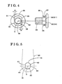
- Fig. 4 is front view and a side view illustrating a stepped bolt serving as a shaft portion according to the embodiment of the present invention
- Fig. 5 is a front view illustrating a bore serving as a bearing portion according to the embodiment of the present invention.
- Fig. 6 is a front view illustrating an operating state of the seat belt buckle rotation angle restriction mechanism according to the embodiment of the present invention.
- Fig. 7 is a front view illustrating the operating state of the seat belt buckle rotation angle restriction mechanism according to the embodiment of the present invention.
- Fig. 8 is a front view illustrating a shaft portion and a bearing portion according to another embodiment of the present invention.
- Fig. 1 is a front view illustrating a portion of a seat belt buckle rotation angle restriction mechanism according to the present embodiment.
- a seat for a vehicle (not shown) is supported by a seat slide apparatus.
- the seat slide apparatus of the present embodiment includes a pair of lower rails 11 and a pair of upper rails 12 supported by the lower rails 11 so as to be slidable thereon.
- the lower rails 11 are fixed on a floor (not shown) so as to extend in a front-rear direction of the vehicle.
- the seat is supported by the upper rails 12 that serve as a seat support member according to the present embodiment.
- One of the pair of lower rails 11 and one of the pair of upper rails 12 are provided at each of right and left sides of a vehicle. However, in Fig. 1 , only one side of the vehicle is illustrated.
- a bracket 13 also serving as a seat support member is fixed to the upper rail 12 so as to upwardly extend therefrom and to be positioned at an outer side of a seat (not shown) in a width direction.
- a buckle support member for a seat belt (hereinafter simply referred to as "buckle support member") 20 including a buckle 21 and a stay 22 is rotatably supported by the bracket 13.
- a stepped bolt 30 illustrated in Fig. 4 and serving as a shaft portion is fixed to the bracket 13.
- the stepped bolt 30 includes first and second outer contact surfaces 31 and 32, and third and fourth outer contact surfaces 33 and 34, each serving as a rotational side surface (i.e., at least two rotational side surfaces according to the present embodiment).
- the first and second outer contact surfaces 31 and 32 are arranged so as to be symmetrical about a rotational center C of the buckle support member 20.
- the third and fourth outer contact surfaces 33 and 34 are arranged so as to be symmetrical about the rotational center C of the buckle support member 20.
- the first outer contact surface 31 and the third outer contact surface 33 form a predetermined angle (i.e., 2 ⁇ ) therebetween while the second outer contact surface 32 and the fourth outer contact surface 34 also form the predetermined angle (i.e., 2 ⁇ ) therebetween.
- the first and second outer contact surfaces 31 and 32 are arranged in parallel with each other while the third and fourth contact surfaces 33 and 34 are also arranged in parallel with each other.
- a side surface 35 connecting the first and third outer contact surfaces 31 and 33; and a side surface 36 connecting the second and fourth outer contact surfaces 32 and 34 are formed in such a way as to match a portion of an outer peripheral surface of a cylindrical column having an axial center equal to the rotational center C.
- a groove 37 for holding a wave washer W is formed at each outer periphery of the side surfaces 35 and 36.
- a screw portion 38 is formed at an end portion of the stepped bolt 30.
- the buckle support member 20 includes a bore 40 serving as a bearing portion. As illustrated in Fig. 5 , the bore 40 forms into a racetrack shape having two linear portions and two curved portions. Thickness surface sides of the two linear portions constitute first and second inner contact surfaces 41 and 42, and third and fourth inner contact surfaces 43 and 44, each serving as a block side surface (i.e., at least two block side surfaces according to the present embodiment).
- the first and second inner contact surfaces 41 and 42 are arranged so as to be symmetrical about the rotational center C of the buckle support member 20.
- the third and fourth inner contact surfaces 43 and 44 are arranged so as to be symmetrical about the rotational center C of the buckle support member 20.
- thickness surface sides of the two curved portions constitute a side surface 45 connecting the first and third inner contact surfaces 41 and 43, and a side surface 46 connecting the second and fourth inner contact surfaces 42 and 44.
- the side surfaces 35 and 36 of the stepped bolt 30 are slidable onto the side surfaces 45 and 46 of the bore 40, respectively.
- the first and second outer contact surfaces 31 and 32, and the first and second inner contact surfaces 41 and 42 will be mainly explained.
- the stepped bolt 30 having the aforementioned structure is attached to the bracket 13 in such a way that a shaft portion of the stepped bolt 30 outwardly extends from the seat as illustrated in Figs. 2 and 3 .
- the buckle support member 20 is attached to the bracket 13 via the wave washer W. That is, when the shaft portion of the stepped bolt 30 is inserted into the bore 40, the side surface 35 connecting the first and third outer contact surfaces 31 and 33, and the side surface 36 connecting the second and fourth outer contact surfaces 32 and 34, are made slidable onto the side surfaces 45 and 46 of the bore 40.
- the stepped bolt 30 When a nut 39 is threaded onto the screw portion 38 of the stepped bolt 30, the stepped bolt 30 is supported so as to be closely in contact with the bracket 13 and the buckle support member 20 as illustrated in Figs. 2 and 3 . Accordingly, the first and second outer contact surfaces 31 and 32 of the stepped bolt 30 are rotatable with the first and second inner contact surfaces 41 and 42, respectively, by a predetermined angle ⁇ at a maximum. In Fig. 1 , the nut 39 is omitted for convenience of explanation.
- the buckle support member 20 is rotatable relative to the bracket 13 within a range of the predetermined angle ⁇ .
- the third and fourth inner contact surfaces 43 and 44 i.e., rotational side surfaces
- the third and fourth outer contact surfaces 33 and 34 of the stepped bolt 30 serve as the block side surfaces.
- the first and second inner contact surfaces 41 and 42 i.e., rotational side surfaces
- the first and second outer contact surfaces 31 and 32 serve as the block side surfaces.
- the cross section of the bore 40 serving as the bearing portion forms into the racetrack shape.
- the cross section of the stepped bolt 30 serving as the shaft portion may form into the racetrack shape.
- the cross section of the bore 40 may form into a shape illustrated in Fig. 8 .
- Fig. 8 the components illustrated in Figs. 4 and 5 are explained by numbers each added by 100.
- the bore 40 is formed at the buckle support member 20 and the stepped bolt 30 is fixed to the bracket 13.
- the stepped bolt 30 may be fixed to the buckle support member 20 and the bore 40 may be formed at the bracket 13.
- the outer contact surfaces of the stepped bolt 30 serve as the rotational side surfaces while the inner contact surfaces of the bore 40 serve as the block side surfaces.
- the seat belt buckle rotation angle restriction mechanism can be basically constituted by the stepped bolt 30 and the bore 40 to thereby achieve an appropriate structure of the restriction mechanism in response to a relationship between the stepped bolt 30 and the bore 40 without being affected by peripheral components, and the like.
- the bracket 13 and the buckle support member 20 can be simply configured to thereby achieve a compact structure of the restriction mechanism with a low cost as a whole.
- a seat belt buckle rotation angle restriction mechanism includes a shaft portion (30) fixed to one of the seat support member (13) and the buckle support member (20), a bearing portion (40) provided at the other one of the seat support member and the buckle support member, the bearing portion roratably accommodating the shaft portion (30), at least two rotational side surfaces (41,42,43,44) provided at one of outer contact surfaces of the shaft portion (30) and inner contact surfaces of the bearing portion (40), the two rotational side surfaces being symmetric about a rotational center (C) of the buckle support member (20), and at least two block side surfaces provided at the other one of the outer contact surfaces and the inner contact surfaces, the two block side surfaces being symmetric about the rotational center (C), each block side surface forming a predetermined angle with each rotational side surface.
Abstract
Description
- This invention generally relates to a seat belt buckle rotation angle restriction mechanism.
- A seat belt attached to a seat for a vehicle is mounted onto a vehicle body by means of a seat belt anchorage. The seat belt anchorage includes a member for supporting the seat to the vehicle body side (hereinafter referred to as "seat support member"). Then, a member for supporting a buckle of the seat belt (hereinafter referred to as "buckle support member") is provided at the seat support member in such a manner as to be rotatable within a predetermined rotation angle. The buckle support member together with the buckle is called an inner belt. For example,
JP2001-180435A -
JP2001-180435A JP2001-180435A - According to the aforementioned rotation restriction mechanism in which the cut and raised portion is formed in the front or rear of the stay, the cut and raised portion or a stopper portion is required to be formed away from a rotational center of the stay. Thus, an arrangement of peripheral components, and the like is restricted or a structure of a peripheral portion is complicated, which may lead to a cost increase or increase in size of the rotation restriction mechanism.
- Thus, a need exists for a seat belt buckle rotation angle restriction mechanism which can restrict a buckle support member for a seat belt to rotate within a predetermined angle relative to a seat support member for a vehicle while achieving a compact size and a low cost.
- According to an aspect of the present invention, a seat belt buckle rotation angle restriction mechanism for restricting a buckle support member for a seat belt to rotate within a predetermined angle range, the buckle support member being rotatably supported by a seat support member for a vehicle, includes a shaft portion fixed to one of the seat support member and the buckle support member, a bearing portion provided at the other one of the seat support member and the buckle support member, the bearing portion accommodating the shaft portion in such a manner that the shaft portion is rotatable, at least two rotational side surfaces provided at one of outer contact surfaces of the shaft portion and inner contact surfaces of the bearing portion, the two rotational side surfaces being symmetric about a rotational center of the buckle support member, and at least two block side surfaces provided at the other one of the outer contact surfaces of the shaft portion and the inner contact surfaces of the bearing portion, the two block side surfaces being symmetric about the rotational center of the buckle support member, each block side surface forming a predetermined angle with each rotational side surface.
- According to the aforementioned invention, the rotation angle restriction mechanism as a whole can achieve a compact structure. Further, each of the support members can be simply configured to thereby achieve a low cost.
- It is preferable that the bearing portion including at least two of the rotational side surfaces may be formed at the buckle support member, and the shaft portion including at least two of the block side surfaces may be fixed to the seat support member.
- Further, it is preferable that the seat support member may include an upper rail being slidable onto a lower rail fixed to the vehicle and a bracket fixed to the upper rail, and the shaft portion may be fixed to the bracket.
- The foregoing and additional features and characteristics of the present invention will become more apparent from the following detailed description considered with reference to the accompanying drawings, wherein:
-
Fig. 1 is a front view illustrating a seat belt buckle rotation angle restriction mechanism according to an embodiment of the present invention; -
Fig. 2 is a plan view illustrating the seat belt buckle rotation angle restriction mechanism according to the embodiment of the present invention; -
Fig. 3 is a partial cross-sectional view illustrating the seat belt buckle rotation angle restriction mechanism according to the embodiment of the present invention; -
Fig. 4 is front view and a side view illustrating a stepped bolt serving as a shaft portion according to the embodiment of the present invention; -
Fig. 5 is a front view illustrating a bore serving as a bearing portion according to the embodiment of the present invention; -
Fig. 6 is a front view illustrating an operating state of the seat belt buckle rotation angle restriction mechanism according to the embodiment of the present invention; -
Fig. 7 is a front view illustrating the operating state of the seat belt buckle rotation angle restriction mechanism according to the embodiment of the present invention; and -
Fig. 8 is a front view illustrating a shaft portion and a bearing portion according to another embodiment of the present invention. - An embodiment of the present invention will be explained with reference to the attached drawings.
Fig. 1 is a front view illustrating a portion of a seat belt buckle rotation angle restriction mechanism according to the present embodiment. A seat for a vehicle (not shown) is supported by a seat slide apparatus. Specifically, the seat slide apparatus of the present embodiment includes a pair oflower rails 11 and a pair ofupper rails 12 supported by thelower rails 11 so as to be slidable thereon. Thelower rails 11 are fixed on a floor (not shown) so as to extend in a front-rear direction of the vehicle. The seat is supported by theupper rails 12 that serve as a seat support member according to the present embodiment. One of the pair oflower rails 11 and one of the pair ofupper rails 12 are provided at each of right and left sides of a vehicle. However, inFig. 1 , only one side of the vehicle is illustrated. - As illustrated in
Fig. 1 , abracket 13 also serving as a seat support member is fixed to theupper rail 12 so as to upwardly extend therefrom and to be positioned at an outer side of a seat (not shown) in a width direction. A buckle support member for a seat belt (hereinafter simply referred to as "buckle support member") 20 including abuckle 21 and astay 22 is rotatably supported by thebracket 13. Then, a steppedbolt 30 illustrated inFig. 4 and serving as a shaft portion is fixed to thebracket 13. The steppedbolt 30 includes first and secondouter contact surfaces outer contact surfaces outer contact surfaces buckle support member 20. In the same way, the third and fourthouter contact surfaces buckle support member 20. - As illustrated in
Fig. 4 , the firstouter contact surface 31 and the thirdouter contact surface 33 form a predetermined angle (i.e., 2·θ) therebetween while the secondouter contact surface 32 and the fourthouter contact surface 34 also form the predetermined angle (i.e., 2·θ) therebetween. In addition, the first and secondouter contact surfaces fourth contact surfaces side surface 35 connecting the first and thirdouter contact surfaces side surface 36 connecting the second and fourthouter contact surfaces Fig. 4 , agroove 37 for holding a wave washer W (seeFig. 2 ) is formed at each outer periphery of theside surfaces screw portion 38 is formed at an end portion of thestepped bolt 30. - The
buckle support member 20 includes abore 40 serving as a bearing portion. As illustrated inFig. 5 , thebore 40 forms into a racetrack shape having two linear portions and two curved portions. Thickness surface sides of the two linear portions constitute first and secondinner contact surfaces inner contact surfaces inner contact surfaces buckle support member 20. In the same way, the third and fourthinner contact surfaces buckle support member 20. Then, thickness surface sides of the two curved portions constitute aside surface 45 connecting the first and thirdinner contact surfaces side surface 46 connecting the second and fourthinner contact surfaces side surfaces stepped bolt 30 are slidable onto theside surfaces bore 40, respectively. In the following, the first and secondouter contact surfaces inner contact surfaces - The stepped
bolt 30 having the aforementioned structure is attached to thebracket 13 in such a way that a shaft portion of the steppedbolt 30 outwardly extends from the seat as illustrated inFigs. 2 and 3 . Then, thebuckle support member 20 is attached to thebracket 13 via the wave washer W. That is, when the shaft portion of the steppedbolt 30 is inserted into thebore 40, theside surface 35 connecting the first and third outer contact surfaces 31 and 33, and theside surface 36 connecting the second and fourth outer contact surfaces 32 and 34, are made slidable onto the side surfaces 45 and 46 of thebore 40. When anut 39 is threaded onto thescrew portion 38 of the steppedbolt 30, the steppedbolt 30 is supported so as to be closely in contact with thebracket 13 and thebuckle support member 20 as illustrated inFigs. 2 and 3 . Accordingly, the first and second outer contact surfaces 31 and 32 of the steppedbolt 30 are rotatable with the first and second inner contact surfaces 41 and 42, respectively, by a predetermined angle θ at a maximum. InFig. 1 , thenut 39 is omitted for convenience of explanation. - According to the aforementioned seat belt buckle rotation angle restriction mechanism of the present embodiment, the
buckle support member 20 is rotatable relative to thebracket 13 within a range of the predetermined angle θ. For example, as illustrated inFig. 6 , in the cases where thebuckle support member 20 is shifted forward of the vehicle and then the third and fourth inner contact surfaces 43 and 44 (i.e., rotational side surfaces) of thebore 40 make contact with the third and fourth outer contact surfaces 33 and 34 of the steppedbolt 30, the rotation of thebuckle support member 20 is impeded. Thus, the third and fourth outer contact surfaces 33 and 34 of the steppedbolt 30 serve as the block side surfaces. On the other hand, as illustrated inFig. 7 , in the cases where thebuckle support member 20 is shifted rearward of the vehicle and then the first and second inner contact surfaces 41 and 42 (i.e., rotational side surfaces) of thebore 40 make contact with the first and second outer contact surfaces 31 and 32 of the steppedbolt 30, the rotation of thebuckle support member 20 is impeded. Thus, the first and second outer contact surfaces 31 and 32 serve as the block side surfaces. - According to the aforementioned seat belt buckle rotation angle restriction mechanism, the cross section of the
bore 40 serving as the bearing portion forms into the racetrack shape. Alternatively, the cross section of the steppedbolt 30 serving as the shaft portion may form into the racetrack shape. In this case, the cross section of thebore 40 may form into a shape illustrated inFig. 8 . InFig. 8 , the components illustrated inFigs. 4 and 5 are explained by numbers each added by 100. - Further, according to the aforementioned seat belt buckle rotation angle restriction mechanism, the
bore 40 is formed at thebuckle support member 20 and the steppedbolt 30 is fixed to thebracket 13. Alternatively, the steppedbolt 30 may be fixed to thebuckle support member 20 and thebore 40 may be formed at thebracket 13. In this case, the outer contact surfaces of the steppedbolt 30 serve as the rotational side surfaces while the inner contact surfaces of thebore 40 serve as the block side surfaces. - Accordingly, the seat belt buckle rotation angle restriction mechanism can be basically constituted by the stepped
bolt 30 and thebore 40 to thereby achieve an appropriate structure of the restriction mechanism in response to a relationship between the steppedbolt 30 and thebore 40 without being affected by peripheral components, and the like. As a result, thebracket 13 and thebuckle support member 20 can be simply configured to thereby achieve a compact structure of the restriction mechanism with a low cost as a whole.
A seat belt buckle rotation angle restriction mechanism includes a shaft portion (30) fixed to one of the seat support member (13) and the buckle support member (20), a bearing portion (40) provided at the other one of the seat support member and the buckle support member, the bearing portion roratably accommodating the shaft portion (30), at least two rotational side surfaces (41,42,43,44) provided at one of outer contact surfaces of the shaft portion (30) and inner contact surfaces of the bearing portion (40), the two rotational side surfaces being symmetric about a rotational center (C) of the buckle support member (20), and at least two block side surfaces provided at the other one of the outer contact surfaces and the inner contact surfaces, the two block side surfaces being symmetric about the rotational center (C), each block side surface forming a predetermined angle with each rotational side surface.
Claims (3)
- A seat belt buckle rotation angle restriction mechanism for restricting a buckle support member (20) for a seat belt to rotate within a predetermined angle range, the buckle support member being rotatably supported by a seat support member (13) for a vehicle, comprising:a shaft portion (30) fixed to one of the seat support member (13) and the buckle support member (20);a bearing portion (40) provided at the other one of the seat support member (13) and the buckle support member (20), the bearing portion (40) supporting the shaft portion (30) in such a manner that the shaft portion is rotatable;at least two rotational side surfaces (41,42,43,44) provided at one of outer contact surfaces of the shaft portion (30) and inner contact surfaces of the bearing portion (40), the two rotational side surfaces being symmetric about a rotational center (C) of the buckle support member (20); andat least two block side surfaces (31, 32, 33, 34) provided at the other one of the outer contact surfaces of the shaft portion (30) and the inner contact surfaces of the bearing portion (40), the two block side surfaces being symmetric about the rotational center (C) of the buckle support member (20), each block side surface forming a predetermined angle with each rotational side surface.
- A seat belt buckle rotation angle restriction mechanism according to claim 1, wherein the bearing portion (40) including at least two of the rotational side surfaces (41, 42, 43, 44) is formed at the buckle support member (20), and the shaft portion (30) including at least two of the block side surfaces (31, 32, 33, 34) is fixed to the seat support member (13).
- A seat belt buckle rotation angle restriction mechanism according to claim 2, wherein the seat support member includes an upper rail (12) being slidable onto a lower rail (11) fixed to the vehicle and a bracket (13) fixed to the upper rail (12), and the shaft portion (30) is fixed to the bracket (13).
Priority Applications (1)
| Application Number | Priority Date | Filing Date | Title |
|---|---|---|---|
| PL07122990T PL1932732T3 (en) | 2006-12-14 | 2007-12-12 | Seat belt buckle rotation angle restriction mechanism |
Applications Claiming Priority (1)
| Application Number | Priority Date | Filing Date | Title |
|---|---|---|---|
| JP2006336684A JP5018059B2 (en) | 2006-12-14 | 2006-12-14 | Seat belt buckle rotation angle regulation mechanism |
Publications (3)
| Publication Number | Publication Date |
|---|---|
| EP1932732A2 true EP1932732A2 (en) | 2008-06-18 |
| EP1932732A3 EP1932732A3 (en) | 2009-05-13 |
| EP1932732B1 EP1932732B1 (en) | 2011-10-26 |
Family
ID=39186155
Family Applications (1)
| Application Number | Title | Priority Date | Filing Date |
|---|---|---|---|
| EP07122990A Expired - Fee Related EP1932732B1 (en) | 2006-12-14 | 2007-12-12 | Seat belt buckle rotation angle restriction mechanism |
Country Status (5)
| Country | Link |
|---|---|
| US (1) | US7527296B2 (en) |
| EP (1) | EP1932732B1 (en) |
| JP (1) | JP5018059B2 (en) |
| CN (1) | CN101204944B (en) |
| PL (1) | PL1932732T3 (en) |
Cited By (3)
| Publication number | Priority date | Publication date | Assignee | Title |
|---|---|---|---|---|
| US20140151992A1 (en) * | 2012-05-24 | 2014-06-05 | Faurecia Autositze Gmbh | Mounting device for securing a seat belt buckle |
| US20140373333A1 (en) * | 2013-06-20 | 2014-12-25 | Toyota Boshoku Kabushiki Kaisha | Manufacturing method for vehicle seat |
| WO2020169431A1 (en) * | 2019-02-20 | 2020-08-27 | Zf Automotive Germany Gmbh | Connection element and securing assembly for securing a seatbelt in a vehicle |
Families Citing this family (6)
| Publication number | Priority date | Publication date | Assignee | Title |
|---|---|---|---|---|
| US7731236B2 (en) * | 2007-02-07 | 2010-06-08 | Gm Global Technology Operations, Inc. | Rotating joint with captured washer assembly and method |
| CN102029970B (en) * | 2010-12-15 | 2012-10-31 | 力帆实业(集团)股份有限公司 | Mounting support of front safety belt snap |
| FR2970443B1 (en) * | 2011-01-18 | 2013-01-04 | Peugeot Citroen Automobiles Sa | BLOCKING THE SAFETY BELT BUCKLE IN CASE OF SHOCK |
| DE102012210536A1 (en) * | 2012-06-21 | 2013-12-24 | Brose Fahrzeugteile Gmbh & Co. Kommanditgesellschaft, Coburg | Vehicle seat assembly, has guide rail connected with vehicle bottom part, and joint kinematics joint lever for vertical adjustment of vehicle seat and belt system attachment arranged at guide rail over common interfaces |
| JP6109221B2 (en) * | 2015-03-23 | 2017-04-05 | 本田技研工業株式会社 | Vehicle seat device |
| US9802570B1 (en) | 2016-09-08 | 2017-10-31 | Fca Us Llc | Movable buckle mounting system |
Citations (6)
| Publication number | Priority date | Publication date | Assignee | Title |
|---|---|---|---|---|
| EP0046268A2 (en) | 1980-08-14 | 1982-02-24 | Union Carbide Corporation | Corrosion resistant autodeposition composition |
| JPH11321559A (en) | 1998-05-12 | 1999-11-24 | Honda Motor Co Ltd | Buckle device for seat belt |
| JP2001180435A (en) | 1999-12-24 | 2001-07-03 | Central Motor Co Ltd | Inner belt rotation regulating mechanism |
| DE10204090C1 (en) | 2002-02-01 | 2003-06-12 | Autoliv Dev | Safety belt lock and fastening system for road vehicle is mounted on arm on pivot with fastening screw and flat coil spring |
| EP1501698B1 (en) | 2002-04-30 | 2005-11-23 | Brose Fahrzeugteile GmbH & Co. KG, Coburg | Longitudinal guide rail for a motor vehicle seat |
| US20060017275A1 (en) | 2004-07-26 | 2006-01-26 | Autoliv Asp, Inc. | Cross-car adjustable strap buckle |
Family Cites Families (15)
| Publication number | Priority date | Publication date | Assignee | Title |
|---|---|---|---|---|
| US2640246A (en) * | 1950-03-17 | 1953-06-02 | United Carr Fastener Corp | Separable headed fastening device |
| JPS562996Y2 (en) * | 1976-07-31 | 1981-01-23 | ||
| JPS6330587Y2 (en) * | 1980-08-15 | 1988-08-16 | ||
| JPS63126155U (en) * | 1987-02-13 | 1988-08-17 | ||
| US5016916A (en) * | 1988-12-24 | 1991-05-21 | Nippon Seiko Kabushiki Kaisha | Mechanism for adjusting the position of shoulder anchor |
| JPH0315248U (en) * | 1989-06-28 | 1991-02-15 | ||
| US5037135A (en) * | 1990-03-14 | 1991-08-06 | Trw Vehicle Safety Systems Inc. | Limited rotation webbing guide |
| US5215332A (en) * | 1990-05-21 | 1993-06-01 | General Motors Corporation | Quick release seat belt anchor |
| US5125611A (en) * | 1991-02-20 | 1992-06-30 | Atwood Industries, Inc. | Vehicle seat adjuster with crash bars |
| US5236220A (en) * | 1992-04-30 | 1993-08-17 | Allied Signal Inc. | Stowable telescoping seat belt mechanism |
| DE29700908U1 (en) * | 1997-01-20 | 1997-05-15 | Trw Repa Gmbh | Belt buckle with mounting bracket |
| JP3745217B2 (en) * | 2000-10-31 | 2006-02-15 | 株式会社東海理化電機製作所 | Buckle device |
| KR100378543B1 (en) * | 2000-12-06 | 2003-03-29 | 델파이 오토모티브 시스템스 성우 주식회사 | Rotating means of buckle for automobile seat belt |
| US7229135B2 (en) * | 2005-05-02 | 2007-06-12 | Autoliv Asp, Inc. | Buckle assembly |
| US7364200B2 (en) * | 2005-09-12 | 2008-04-29 | Nissan Technical Center North America, Inc. | Vehicle seatbelt restraining apparatus |
-
2006
- 2006-12-14 JP JP2006336684A patent/JP5018059B2/en not_active Expired - Fee Related
-
2007
- 2007-12-12 PL PL07122990T patent/PL1932732T3/en unknown
- 2007-12-12 US US11/954,884 patent/US7527296B2/en not_active Expired - Fee Related
- 2007-12-12 EP EP07122990A patent/EP1932732B1/en not_active Expired - Fee Related
- 2007-12-13 CN CN200710195364XA patent/CN101204944B/en not_active Expired - Fee Related
Patent Citations (6)
| Publication number | Priority date | Publication date | Assignee | Title |
|---|---|---|---|---|
| EP0046268A2 (en) | 1980-08-14 | 1982-02-24 | Union Carbide Corporation | Corrosion resistant autodeposition composition |
| JPH11321559A (en) | 1998-05-12 | 1999-11-24 | Honda Motor Co Ltd | Buckle device for seat belt |
| JP2001180435A (en) | 1999-12-24 | 2001-07-03 | Central Motor Co Ltd | Inner belt rotation regulating mechanism |
| DE10204090C1 (en) | 2002-02-01 | 2003-06-12 | Autoliv Dev | Safety belt lock and fastening system for road vehicle is mounted on arm on pivot with fastening screw and flat coil spring |
| EP1501698B1 (en) | 2002-04-30 | 2005-11-23 | Brose Fahrzeugteile GmbH & Co. KG, Coburg | Longitudinal guide rail for a motor vehicle seat |
| US20060017275A1 (en) | 2004-07-26 | 2006-01-26 | Autoliv Asp, Inc. | Cross-car adjustable strap buckle |
Cited By (5)
| Publication number | Priority date | Publication date | Assignee | Title |
|---|---|---|---|---|
| US20140151992A1 (en) * | 2012-05-24 | 2014-06-05 | Faurecia Autositze Gmbh | Mounting device for securing a seat belt buckle |
| US8950782B2 (en) * | 2012-05-24 | 2015-02-10 | Faurecia Autositze Gmbh | Mounting device for securing a seat belt buckle |
| US20140373333A1 (en) * | 2013-06-20 | 2014-12-25 | Toyota Boshoku Kabushiki Kaisha | Manufacturing method for vehicle seat |
| US9573505B2 (en) * | 2013-06-20 | 2017-02-21 | Toyota Boshoku Kabushiki Kaisha | Manufacturing method for vehicle seat |
| WO2020169431A1 (en) * | 2019-02-20 | 2020-08-27 | Zf Automotive Germany Gmbh | Connection element and securing assembly for securing a seatbelt in a vehicle |
Also Published As
| Publication number | Publication date |
|---|---|
| JP2008149741A (en) | 2008-07-03 |
| CN101204944A (en) | 2008-06-25 |
| EP1932732A3 (en) | 2009-05-13 |
| US7527296B2 (en) | 2009-05-05 |
| PL1932732T3 (en) | 2012-03-30 |
| EP1932732B1 (en) | 2011-10-26 |
| CN101204944B (en) | 2010-09-15 |
| JP5018059B2 (en) | 2012-09-05 |
| US20080143093A1 (en) | 2008-06-19 |
Similar Documents
| Publication | Publication Date | Title |
|---|---|---|
| EP1932732A2 (en) | Seat belt buckle rotation angle restriction mechanism | |
| US7832806B2 (en) | Seat apparatus for vehicle | |
| US9376139B2 (en) | Ball screw having bearing compensation | |
| US9597980B2 (en) | Conveyance seat | |
| US9272643B2 (en) | Vehicle seat | |
| US7641164B2 (en) | Power seat slide apparatus for vehicle | |
| US20170050539A1 (en) | Vehicle seat and vehicle | |
| US20080022796A1 (en) | Steering apparatus equipped with ring type support yoke | |
| US6814406B2 (en) | Seat vertical position adjusting device | |
| US10946779B2 (en) | Vehicle seat | |
| US20070046090A1 (en) | Seat reclining device | |
| US6357314B1 (en) | Rack-and-pinion steering gear | |
| JP2007045276A (en) | Steering device | |
| JP5380858B2 (en) | Vehicle seat reclining device | |
| JP2008265378A (en) | Vehicle seat | |
| JP2002036930A (en) | Table for car seat | |
| JPH086597Y2 (en) | Power seat slide device for vehicles | |
| KR102067485B1 (en) | Dive pivot device of vehicle seat | |
| JP2005104429A (en) | Column assist type electric power steering device | |
| KR102219236B1 (en) | Arm-rest tilting apparatus for vehicle | |
| JP2006213122A (en) | Seat structure | |
| WO2007104906A1 (en) | Recliner mechanism | |
| US20070170763A1 (en) | Continuously adjustable seat back hinge mounting | |
| KR20010081186A (en) | An arm rest for an automobile | |
| JP2009047197A (en) | Retaining structure for crank member |
Legal Events
| Date | Code | Title | Description |
|---|---|---|---|
| PUAI | Public reference made under article 153(3) epc to a published international application that has entered the european phase |
Free format text: ORIGINAL CODE: 0009012 |
|
| AK | Designated contracting states |
Kind code of ref document: A2 Designated state(s): AT BE BG CH CY CZ DE DK EE ES FI FR GB GR HU IE IS IT LI LT LU LV MC MT NL PL PT RO SE SI SK TR |
|
| AX | Request for extension of the european patent |
Extension state: AL BA HR MK RS |
|
| PUAL | Search report despatched |
Free format text: ORIGINAL CODE: 0009013 |
|
| AK | Designated contracting states |
Kind code of ref document: A3 Designated state(s): AT BE BG CH CY CZ DE DK EE ES FI FR GB GR HU IE IS IT LI LT LU LV MC MT NL PL PT RO SE SI SK TR |
|
| AX | Request for extension of the european patent |
Extension state: AL BA HR MK RS |
|
| 17P | Request for examination filed |
Effective date: 20091111 |
|
| AKX | Designation fees paid |
Designated state(s): DE FR GB PL TR |
|
| GRAP | Despatch of communication of intention to grant a patent |
Free format text: ORIGINAL CODE: EPIDOSNIGR1 |
|
| GRAS | Grant fee paid |
Free format text: ORIGINAL CODE: EPIDOSNIGR3 |
|
| GRAA | (expected) grant |
Free format text: ORIGINAL CODE: 0009210 |
|
| AK | Designated contracting states |
Kind code of ref document: B1 Designated state(s): DE FR GB PL TR |
|
| REG | Reference to a national code |
Ref country code: GB Ref legal event code: FG4D |
|
| REG | Reference to a national code |
Ref country code: DE Ref legal event code: R096 Ref document number: 602007018162 Country of ref document: DE Effective date: 20111222 |
|
| REG | Reference to a national code |
Ref country code: PL Ref legal event code: T3 |
|
| PLBE | No opposition filed within time limit |
Free format text: ORIGINAL CODE: 0009261 |
|
| STAA | Information on the status of an ep patent application or granted ep patent |
Free format text: STATUS: NO OPPOSITION FILED WITHIN TIME LIMIT |
|
| 26N | No opposition filed |
Effective date: 20120727 |
|
| REG | Reference to a national code |
Ref country code: DE Ref legal event code: R097 Ref document number: 602007018162 Country of ref document: DE Effective date: 20120727 |
|
| PGFP | Annual fee paid to national office [announced via postgrant information from national office to epo] |
Ref country code: TR Payment date: 20131125 Year of fee payment: 7 |
|
| PGFP | Annual fee paid to national office [announced via postgrant information from national office to epo] |
Ref country code: DE Payment date: 20141209 Year of fee payment: 8 Ref country code: GB Payment date: 20141210 Year of fee payment: 8 |
|
| PGFP | Annual fee paid to national office [announced via postgrant information from national office to epo] |
Ref country code: FR Payment date: 20141208 Year of fee payment: 8 Ref country code: PL Payment date: 20141015 Year of fee payment: 8 |
|
| REG | Reference to a national code |
Ref country code: DE Ref legal event code: R119 Ref document number: 602007018162 Country of ref document: DE |
|
| GBPC | Gb: european patent ceased through non-payment of renewal fee |
Effective date: 20151212 |
|
| REG | Reference to a national code |
Ref country code: FR Ref legal event code: ST Effective date: 20160831 |
|
| PG25 | Lapsed in a contracting state [announced via postgrant information from national office to epo] |
Ref country code: GB Free format text: LAPSE BECAUSE OF NON-PAYMENT OF DUE FEES Effective date: 20151212 Ref country code: DE Free format text: LAPSE BECAUSE OF NON-PAYMENT OF DUE FEES Effective date: 20160701 |
|
| PG25 | Lapsed in a contracting state [announced via postgrant information from national office to epo] |
Ref country code: FR Free format text: LAPSE BECAUSE OF NON-PAYMENT OF DUE FEES Effective date: 20151231 |
|
| PG25 | Lapsed in a contracting state [announced via postgrant information from national office to epo] |
Ref country code: PL Free format text: LAPSE BECAUSE OF NON-PAYMENT OF DUE FEES Effective date: 20151212 |
|
| PG25 | Lapsed in a contracting state [announced via postgrant information from national office to epo] |
Ref country code: TR Free format text: LAPSE BECAUSE OF NON-PAYMENT OF DUE FEES Effective date: 20151212 |