EP1932709A1 - Method for manufacturing a panel of an instrument cluster for a vehicle and panel obtained by means of such method - Google Patents
Method for manufacturing a panel of an instrument cluster for a vehicle and panel obtained by means of such method Download PDFInfo
- Publication number
- EP1932709A1 EP1932709A1 EP06425831A EP06425831A EP1932709A1 EP 1932709 A1 EP1932709 A1 EP 1932709A1 EP 06425831 A EP06425831 A EP 06425831A EP 06425831 A EP06425831 A EP 06425831A EP 1932709 A1 EP1932709 A1 EP 1932709A1
- Authority
- EP
- European Patent Office
- Prior art keywords
- chromable
- frame element
- panel
- mask
- shaped ring
- Prior art date
- Legal status (The legal status is an assumption and is not a legal conclusion. Google has not performed a legal analysis and makes no representation as to the accuracy of the status listed.)
- Granted
Links
Images

Classifications
-
- B—PERFORMING OPERATIONS; TRANSPORTING
- B60—VEHICLES IN GENERAL
- B60K—ARRANGEMENT OR MOUNTING OF PROPULSION UNITS OR OF TRANSMISSIONS IN VEHICLES; ARRANGEMENT OR MOUNTING OF PLURAL DIVERSE PRIME-MOVERS IN VEHICLES; AUXILIARY DRIVES FOR VEHICLES; INSTRUMENTATION OR DASHBOARDS FOR VEHICLES; ARRANGEMENTS IN CONNECTION WITH COOLING, AIR INTAKE, GAS EXHAUST OR FUEL SUPPLY OF PROPULSION UNITS IN VEHICLES
- B60K37/00—Dashboards
- B60K37/20—Dashboard panels
-
- B—PERFORMING OPERATIONS; TRANSPORTING
- B60—VEHICLES IN GENERAL
- B60Y—INDEXING SCHEME RELATING TO ASPECTS CROSS-CUTTING VEHICLE TECHNOLOGY
- B60Y2410/00—Constructional features of vehicle sub-units
- B60Y2410/12—Production or manufacturing of vehicle parts
Definitions
- the present invention relates to a method for manufacturing a panel of an instrument cluster of a vehicle and to a panel obtained by means of such method.
- the aforesaid instrument clusters comprise a central shaped body provided with openings adapted to accommodate the onboard instruments, and a panel connected to the front part of the central body with the purpose of conferring a particular aesthetic appearance to the instrument cluster.
- the panel comprises a mask which presents openings corresponding to the openings of the central body, and shaped frame rings which are fastened along the periphery of the mask openings and have the purpose of further improving the appearance of the instrument cluster.
- the manufacturing methods of such panels contemplate in order: the moulding of the mask, the making of a plurality of holes distributed along the periphery of the mask openings, the moulding of metallic material shaped rings, the chrome-plating of the shaped rings, and the fastening of the shaped rings about the mask openings by means of a fitting mechanism, i.e. by engaging corresponding teeth arranged on the internal surface of the rings with the holes distributed along the periphery of the mask openings.
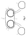
- numeral 1 indicates a panel for an instrument cluster of a vehicle (not shown in the figure), comprising a mask 2 in which, for example, two openings 3 of essentially circular shape are obtained to accommodated onboard instruments (not shown in the figure), and two shaped chrome-plated rings 4, also of essentially circular shape, each fastened about a peripheral edge of opening 3.
- each ring 4 presents the same shape as opening 3 which it surrounds thus making the appearance of panel 1 more pleasant.
- Figure 2 shows the different steps of the manufacturing method of a panel for an instrument cluster of a vehicle, for example of the type shown in figure 1 or in figure 3b .
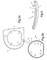
- mask 2 is moulded in a specific moulding press making openings 3 and, as shown by the portion of a mask of a panel of an instrument cluster illustrated in figure 3a , with a plurality of holes 5, four holes in the example shown in figure 3a , distributed along edge 6 of each opening 3.
- rings 4 are moulded by means of a single mould, having the shape of ring 4, which is passed in a specific moulding press.
- a frame element 7 is moulded having the same shape as opening 3 of mask 2 and provided with a plurality of teeth 8, four integral teeth in the example of figure 3b , which protrude from a wall 9 of frame element 7 extending in a direction essentially transversal to the plane of wall 9.
- Teeth 8 are spaced out along wall 9 and arranged in positions corresponding to the positions of holes 5 of mask 2 for fastening frame element 7 to mask 2.
- frame element 7 of ring 4 is made of chromable material, preferable plastic material, because, as known, plastic materials allow to obtain objects of any shape by means of simple moulding procedures.
- Frame element 7 of ring 4 could be formed, for example, by Luran ® which is a material formed by an acrylonitrile and butyl-acrylate based resin.
- teeth 8 are made in the same material as frame element 7 because they are moulded together with frame element 7.
- teeth 8 could be made of a different material from that of frame element 7 in a subsequent step.
- ribs 10 ( figures 3b and 4 ) of non-chromable material or partially chromable material, preferably plastic, such as for example Terluran ® , which is a material formed by an acrylonitrile, butadiene and styrene based resin.
- plastic such as for example Terluran ® , which is a material formed by an acrylonitrile, butadiene and styrene based resin.
- Terluran ® is a material formed by an acrylonitrile, butadiene and styrene based resin.
- Moulding press thus produces shaped ring 4 prior to chrome-plating which, as shown in figures 3b and 4 , comprises: frame element 7, teeth 8 and ribs 10 which extend along wall 9 of frame element 7.
- ribs 10 are moulded preferably using the same material with which mask 2 was moulded or using a material which is compatible with that of mask 2 from the welding point of view, by means of which chrome-plated ring 4 is fastened to mask 2, as contemplated in the last step of the method of the invention.
- shaped ring 4 is chrome-plated by immersing shaped ring 4 in a series of baths containing mineral salts which, in virtue of a high electrical voltage applied between the container in which shaped ring 4 is immersed and some metallic plates immersed in the bath itself, are selectively deposited on shaped ring 4.
- a shaped chrome-plated ring 4 is indeed obtained in which frame element 7 and the teeth are entirely chrome-plated, and ribs 10 are either free from chrome-plating or partially chrome-plated due to the different material used to form them.
- shaped chrome-plated ring 4 is firstly fastened onto mask 2 engaging teeth 8 in corresponding holes 5 of mask 2 and then welded onto mask 2 (by means of known techniques), e.g. by means of ultrasounds.
- ribs 10 of shaped chrome-plated ring 4 are liquefied by stably fastening frame element 7 onto the surface of mask 2.
- the main advantage of the method of the invention is that of allowing to manufacture shaped chrome-plated rings of any shape in a simple, cost-effective manner and to obtain chrome-plated rings with the same chrome-plating appearance features and the same stability as chrome-plated metal rings.
- teeth 8 and ribs 10 may be formed by the same chromable material as frame element 7, for example, in the case in which no non-chromable or partially chromable material is available for making ribs 10.
- ribs 10 before the step of chrome-plating the ring 4, ribs 10 must be painted with a non-chromable material, so that the surfaces of ribs 10 are entirely coated by such material, not chrome-plated during the chrome-plating step of ring 4, and may thus be welded by ultrasounds onto mask 2.
- the method of the invention may not comprise the steps related to the making of holes 5 in mask 2 and to the making of teeth 8 on surface 9 of frame element 7.
- chrome-plated ring 4 not being provided with teeth, would be welded directly onto mask 2.
Landscapes
- Engineering & Computer Science (AREA)
- Chemical & Material Sciences (AREA)
- Combustion & Propulsion (AREA)
- Transportation (AREA)
- Mechanical Engineering (AREA)
- Instrument Panels (AREA)
Abstract
Description
- The present invention relates to a method for manufacturing a panel of an instrument cluster of a vehicle and to a panel obtained by means of such method.
- As it is known, modern motor vehicles are equipped with an instrument cluster of analogue or digital type for displaying magnitudes such as, for example, the motor vehicle speed, the engine speed, the fuel level, etc., provided with a plurality of optical indicators of the motor vehicle state indicating, for example, lights on, engine oil level, coolant water temperature, etc.
- Generally, the aforesaid instrument clusters comprise a central shaped body provided with openings adapted to accommodate the onboard instruments, and a panel connected to the front part of the central body with the purpose of conferring a particular aesthetic appearance to the instrument cluster. Specifically, the panel comprises a mask which presents openings corresponding to the openings of the central body, and shaped frame rings which are fastened along the periphery of the mask openings and have the purpose of further improving the appearance of the instrument cluster.
- Generally, the manufacturing methods of such panels contemplate in order: the moulding of the mask, the making of a plurality of holes distributed along the periphery of the mask openings, the moulding of metallic material shaped rings, the chrome-plating of the shaped rings, and the fastening of the shaped rings about the mask openings by means of a fitting mechanism, i.e. by engaging corresponding teeth arranged on the internal surface of the rings with the holes distributed along the periphery of the mask openings.
- The known methods used to manufacture such panels are particularly disadvantageous from the point of view of costs and flexibility if a frequent modification of the shape of the panel openings which accommodate the instruments is required, e.g. for reasons of appearance. Indeed, in such case, it is necessary to mould both a new mask and new shaped rings of different shape. The moulding of new shaped rings of different shape is however not very cost-effective and not simple to implement because, due to the metallic material, a different moulding press is required with respect to the previously used one.
- It is the object of the present invention to provide a method for manufacturing a panel for an instrument cluster of a vehicle, which is simple, cost-effective and flexible, and a panel for an instrument cluster of a vehicle manufactured according to such method.
- According to the present invention, a method for manufacturing a panel for an instrument cluster of a vehicle and a panel for an instrument cluster of a vehicle manufactured according to such method are suggested, as defined in the attached claims.
- For a better understanding of the present invention, a preferred first embodiment will now be described by way of non-limitative example only and with reference to the accompanying drawings, in which:
-
figure 1 shows a front view of a panel of an instrument cluster of a vehicle and a plurality of shaped chrome-plated rings for such panel; -
figure 2 shows a flow chart of the method for manufacturing a panel for an instrument cluster of a vehicle, according to the present invention; -
figures 3a and 3b respectively show a portion of a mask of a panel of an instrument cluster and a bottom view of a shaped chrome-plated ring, for the mask infigure 3a ; and -
figure 4 shows, in perspective view and magnified scale, a portion of the ring infigure 3b . - In
figure 1 ,numeral 1 indicates a panel for an instrument cluster of a vehicle (not shown in the figure), comprising amask 2 in which, for example, twoopenings 3 of essentially circular shape are obtained to accommodated onboard instruments (not shown in the figure), and two shaped chrome-platedrings 4, also of essentially circular shape, each fastened about a peripheral edge ofopening 3. In this manner, eachring 4 presents the same shape as opening 3 which it surrounds thus making the appearance ofpanel 1 more pleasant. -
Figure 2 shows the different steps of the manufacturing method of a panel for an instrument cluster of a vehicle, for example of the type shown infigure 1 or infigure 3b . - Specifically, as shown in
block 20 of the flow chart offigure 2 , in a first step of the method,mask 2 is moulded in a specific mouldingpress making openings 3 and, as shown by the portion of a mask of a panel of an instrument cluster illustrated infigure 3a , with a plurality ofholes 5, four holes in the example shown infigure 3a , distributed alongedge 6 of eachopening 3. - Once
mask 2 is made, during the further steps of the method shown inblocks figure 2 ,rings 4 are moulded by means of a single mould, having the shape ofring 4, which is passed in a specific moulding press. - Specifically, in a further step of the method, shown in
block 30 offigure 2 as a sequential operation (it is however apparent that the operations ofblocks frame element 7 is moulded having the same shape as opening 3 ofmask 2 and provided with a plurality ofteeth 8, four integral teeth in the example offigure 3b , which protrude from awall 9 offrame element 7 extending in a direction essentially transversal to the plane ofwall 9. -
Teeth 8 are spaced out alongwall 9 and arranged in positions corresponding to the positions ofholes 5 ofmask 2 for fasteningframe element 7 tomask 2. - Specifically,
frame element 7 ofring 4 is made of chromable material, preferable plastic material, because, as known, plastic materials allow to obtain objects of any shape by means of simple moulding procedures.Frame element 7 ofring 4 could be formed, for example, by Luran® which is a material formed by an acrylonitrile and butyl-acrylate based resin. - Specifically, in the aforesaid embodiment of the invention,
teeth 8 are made in the same material asframe element 7 because they are moulded together withframe element 7. - It is however apparent that
teeth 8 could be made of a different material from that offrame element 7 in a subsequent step. - After moulding
frame element 7, in the next step,block 40 offigure 2 , onwall 9 offrame element 7 there are moulded ribs 10 (figures 3b and 4 ) of non-chromable material or partially chromable material, preferably plastic, such as for example Terluran®, which is a material formed by an acrylonitrile, butadiene and styrene based resin. Eachrib 10 displays radial dimensions smaller than the radial dimensions offrame element 7 and smaller height than the height ofteeth 8. End portions ofadjacent ribs 10 are separated by a portion ofwall 9 from which atooth 8 extends. - Moulding press thus produces
shaped ring 4 prior to chrome-plating which, as shown infigures 3b and 4 , comprises:frame element 7,teeth 8 andribs 10 which extend alongwall 9 offrame element 7. - Specifically,
ribs 10 are moulded preferably using the same material with whichmask 2 was moulded or using a material which is compatible with that ofmask 2 from the welding point of view, by means of which chrome-platedring 4 is fastened tomask 2, as contemplated in the last step of the method of the invention. - Specifically, the need to make
frame element 7 andribs 10 of chromable material and non-chromable material respectively, essentially derives from the fact that chrome-plated objects are not suitable to be welded, for example by ultrasounds, regardless of the material by which they are formed. - In the next step, shown in
block 50 offigure 2 , the chrome-plating ofshaped ring 4 is thus performed in the intrinsically known manner. Specifically,shaped ring 4 is chrome-plated by immersingshaped ring 4 in a series of baths containing mineral salts which, in virtue of a high electrical voltage applied between the container in which shapedring 4 is immersed and some metallic plates immersed in the bath itself, are selectively deposited onshaped ring 4. At the end of the chrome-plating step, a shaped chrome-platedring 4 is indeed obtained in whichframe element 7 and the teeth are entirely chrome-plated, andribs 10 are either free from chrome-plating or partially chrome-plated due to the different material used to form them. - Once the chrome-plating step is ended, during the next step of the method,
block 60 offigure 2 , shaped chrome-platedring 4 is firstly fastened ontomask 2 engagingteeth 8 incorresponding holes 5 ofmask 2 and then welded onto mask 2 (by means of known techniques), e.g. by means of ultrasounds. During ultrasound welding,ribs 10 of shaped chrome-platedring 4 are liquefied by stably fasteningframe element 7 onto the surface ofmask 2. - The main advantage of the method of the invention is that of allowing to manufacture shaped chrome-plated rings of any shape in a simple, cost-effective manner and to obtain chrome-plated rings with the same chrome-plating appearance features and the same stability as chrome-plated metal rings.
- It is finally apparent that changes and variations can be made to the methods here described and illustrated without however departing from the scope of protection of the present invention, as defined by the accompanying claims.
- In a second embodiment different from the first one, for example,
teeth 8 andribs 10 may be formed by the same chromable material asframe element 7, for example, in the case in which no non-chromable or partially chromable material is available for makingribs 10. In this case, before the step of chrome-plating thering 4,ribs 10 must be painted with a non-chromable material, so that the surfaces ofribs 10 are entirely coated by such material, not chrome-plated during the chrome-plating step ofring 4, and may thus be welded by ultrasounds ontomask 2. - In a further embodiment, moreover, regardless of whether the ring is made according to the first or second described embodiments, the method of the invention may not comprise the steps related to the making of
holes 5 inmask 2 and to the making ofteeth 8 onsurface 9 offrame element 7. In such case, chrome-platedring 4, not being provided with teeth, would be welded directly ontomask 2.
Claims (11)
- A method for manufacturing a panel (1) for an instrument cluster of a vehicle, said panel comprising a mask (2) provided with at least one opening (3) for accommodating an instrument and at least one shaped ring (4) fastenable along the edge of said opening (3), said shaped ring comprising a frame element (7) formed by chromable material and at least one portion (10) carried by said frame element (7), said portion (10) comprising a non-chromable or partial chromable surface, and being adapted to be welded onto said mask (2),
said method being characterised in that it comprises the steps of:- making said mask (2);- making said frame element (7);- making said portion (10) and associating it to frame element (7) making said shaped ring (4);- subjecting said shaped ring (4) to a chrome-plating process; and- welding said shaped ring (4) onto said mask (2) of said panel (1) obtaining the fusion (10) of said portion. - A method according to claim 1, wherein said portion (10) is entirely made of non-chromable or partially chromable material.
- A method according to claim 1, wherein said portion (10) is formed by the same chromable material as said frame element (7) and wherein making said portion (10) and associating it to the frame element (7) making said shaped ring (4) comprises the step of:- coating at least one surface of said portion (10) with a non-chromable or partially chromable material.
- A method according to claims 1-3, wherein said mask (3) comprises at least one fitting hole (5) for the fastening of said shaped ring (4), further comprising a positioning step in which the following steps are performed:- making at least one tooth (8) on said wall (9) of said frame element (7); and- fastening said shaped tooth (4) to said mask (2) engaging said tooth (8) with said fitting hole (5) before performing said welding step.
- A panel (1) for an instrument cluster of a vehicle, manufactured according to the method of claims from 1 to 4, characterised in that it comprises a mask (2) provided with at least one opening (3) for accommodating at least one instrument, and at least one shaped ring (4) fastenable along the edge of said opening (3), said shaped ring being characterised in that it comprises a frame element (7) formed by chromable material and at least one portion (10) carried by said frame element (7), said portion comprising at least a surface formed by non-chromable or partially chromable material and being adapted to be welded onto said mask (2) .
- A panel (1) according to claim 5, wherein said frame element (7) is made of chromable material and said portion (10) is entirely made of non-chromable o partially chromable material.
- A panel (1) according to claim 5, wherein said portion (10) is formed by the same chromable material as said frame element (7) .
- A panel (1) according to claims 5-7, wherein said frame element (7) is formed by chromable plastic material.
- A panel (1) according to any of the claims from 5 to 8, wherein said mask (3) comprises at least one fitting hole (5) and wherein said shaped ring (4) comprises at least one tooth (8) which protrudes from one wall (9) of said frame element (7) to be engaged with said fitting hole (5) of said mask (3).
- A panel (1) according to any of the claims from 5 to 9, wherein said portion (10) carried by said frame element (7) is a rib.
- A panel (1) according to any of the claims from 5 to 10, characterised in that it comprises a plurality of teeth (8) and a plurality of adjacent ribs (10) reciprocally separated by a portion of said wall (9) of said frame element (7), from which a tooth protrudes (8) .
Priority Applications (3)
| Application Number | Priority Date | Filing Date | Title |
|---|---|---|---|
| EP06425831A EP1932709B1 (en) | 2006-12-12 | 2006-12-12 | Method for manufacturing a panel of an instrument cluster for a vehicle and panel obtained by means of such method |
| DE602006007478T DE602006007478D1 (en) | 2006-12-12 | 2006-12-12 | Method for producing a panel of a combination instrument for a vehicle and panel produced by means of such a method |
| ES06425831T ES2327155T3 (en) | 2006-12-12 | 2006-12-12 | METHOD FOR MANUFACTURING A ROLE OF A TABLE OF INSTRUMENTS OF A VEHICLE AND PANEL OBTAINED FROM SUCH METHOD. |
Applications Claiming Priority (1)
| Application Number | Priority Date | Filing Date | Title |
|---|---|---|---|
| EP06425831A EP1932709B1 (en) | 2006-12-12 | 2006-12-12 | Method for manufacturing a panel of an instrument cluster for a vehicle and panel obtained by means of such method |
Publications (2)
| Publication Number | Publication Date |
|---|---|
| EP1932709A1 true EP1932709A1 (en) | 2008-06-18 |
| EP1932709B1 EP1932709B1 (en) | 2009-06-24 |
Family
ID=37964765
Family Applications (1)
| Application Number | Title | Priority Date | Filing Date |
|---|---|---|---|
| EP06425831A Not-in-force EP1932709B1 (en) | 2006-12-12 | 2006-12-12 | Method for manufacturing a panel of an instrument cluster for a vehicle and panel obtained by means of such method |
Country Status (3)
| Country | Link |
|---|---|
| EP (1) | EP1932709B1 (en) |
| DE (1) | DE602006007478D1 (en) |
| ES (1) | ES2327155T3 (en) |
Cited By (2)
| Publication number | Priority date | Publication date | Assignee | Title |
|---|---|---|---|---|
| US9845009B2 (en) | 2014-05-30 | 2017-12-19 | Nissan North America, Inc. | Meter cluster seal |
| US10737530B2 (en) * | 2015-05-14 | 2020-08-11 | Lacks Enterprises, Inc. | Two-shot molding for selectively metalizing parts |
Citations (4)
| Publication number | Priority date | Publication date | Assignee | Title |
|---|---|---|---|---|
| US4170524A (en) * | 1976-06-25 | 1979-10-09 | Nissan Motor Company, Ltd. | Method of partially plating article or synthetic resin |
| US5452931A (en) * | 1993-07-30 | 1995-09-26 | Lacks Industries, Inc. | Electroplated thermoplastic automotive grille having improved flexibility |
| JP2001343259A (en) * | 2000-05-31 | 2001-12-14 | Nippon Seiki Co Ltd | Measuring instrument |
| WO2004012955A2 (en) * | 2002-08-03 | 2004-02-12 | John Mcgavigan Limited | Display devices including a sheet form member |
-
2006
- 2006-12-12 ES ES06425831T patent/ES2327155T3/en active Active
- 2006-12-12 DE DE602006007478T patent/DE602006007478D1/en active Active
- 2006-12-12 EP EP06425831A patent/EP1932709B1/en not_active Not-in-force
Patent Citations (4)
| Publication number | Priority date | Publication date | Assignee | Title |
|---|---|---|---|---|
| US4170524A (en) * | 1976-06-25 | 1979-10-09 | Nissan Motor Company, Ltd. | Method of partially plating article or synthetic resin |
| US5452931A (en) * | 1993-07-30 | 1995-09-26 | Lacks Industries, Inc. | Electroplated thermoplastic automotive grille having improved flexibility |
| JP2001343259A (en) * | 2000-05-31 | 2001-12-14 | Nippon Seiki Co Ltd | Measuring instrument |
| WO2004012955A2 (en) * | 2002-08-03 | 2004-02-12 | John Mcgavigan Limited | Display devices including a sheet form member |
Non-Patent Citations (1)
| Title |
|---|
| SABINE PHILIPP: "Presse Information: Aussen Metall - innen Kunststoff: Ein World Grade ABS als Galvanomarke", 25 August 2004, BASF AKTIENGESELLSCHAFT, XP002431976 * |
Cited By (3)
| Publication number | Priority date | Publication date | Assignee | Title |
|---|---|---|---|---|
| US9845009B2 (en) | 2014-05-30 | 2017-12-19 | Nissan North America, Inc. | Meter cluster seal |
| US10173527B2 (en) | 2014-05-30 | 2019-01-08 | Nissan North America, Inc. | Meter cluster seal |
| US10737530B2 (en) * | 2015-05-14 | 2020-08-11 | Lacks Enterprises, Inc. | Two-shot molding for selectively metalizing parts |
Also Published As
| Publication number | Publication date |
|---|---|
| ES2327155T3 (en) | 2009-10-26 |
| DE602006007478D1 (en) | 2009-08-06 |
| EP1932709B1 (en) | 2009-06-24 |
Similar Documents
| Publication | Publication Date | Title |
|---|---|---|
| JP2017095738A (en) | Resin plated product and production method thereof | |
| US12083871B2 (en) | Device for the edge sealing of a part or a window pane of a vehicle body and method for producing the sealing device | |
| KR101093516B1 (en) | Car radiator grille | |
| CN109996660A (en) | Selective chromium plating vehicle antenna cover and its manufacturing method | |
| CN102485540A (en) | Component Construction of the Dashboard | |
| US20080063836A1 (en) | Metallized plastic component with a display area and method for manufacture | |
| US20160312974A1 (en) | Galvanically decorated decorative element with contour light | |
| US7367103B2 (en) | Method of forming a vehicle component | |
| EP1932709B1 (en) | Method for manufacturing a panel of an instrument cluster for a vehicle and panel obtained by means of such method | |
| US7344670B2 (en) | Lost core plastic molding process for transferring, positioning and molding inserts into a plastic part | |
| US6312773B1 (en) | Front frame and method for producing it | |
| JP2020050215A (en) | Vehicle body lower part structure | |
| JPS6344572B2 (en) | ||
| US20080311354A1 (en) | Method for producing resin plated product and resin molded product to be plated used therefor | |
| JP2000016136A (en) | Fitting construction of foot rest for automobile | |
| US5484516A (en) | Resin products and process for producing the same | |
| US7116559B2 (en) | Snap-in cluster attachment | |
| JP5141194B2 (en) | Vehicle front structure | |
| JP2006247972A (en) | Composite member and manufacturing method thereof | |
| EP0769405A1 (en) | Transparent cover for an instrument panel, in particular for motor vehicles | |
| KR20210151097A (en) | Vehicle-window glass assembly and manufacturing method thereof | |
| CN111629924B (en) | Plastic container of modular construction | |
| JP2011037047A (en) | Design component for automobile | |
| JP2026504982A (en) | Method for manufacturing a component, in particular a panel, for an automobile | |
| JP2001303292A (en) | Method for manufacturing partially plated resin products |
Legal Events
| Date | Code | Title | Description |
|---|---|---|---|
| PUAI | Public reference made under article 153(3) epc to a published international application that has entered the european phase |
Free format text: ORIGINAL CODE: 0009012 |
|
| 17P | Request for examination filed |
Effective date: 20080331 |
|
| AK | Designated contracting states |
Kind code of ref document: A1 Designated state(s): AT BE BG CH CY CZ DE DK EE ES FI FR GB GR HU IE IS IT LI LT LU LV MC NL PL PT RO SE SI SK TR |
|
| AX | Request for extension of the european patent |
Extension state: AL BA HR MK RS |
|
| GRAP | Despatch of communication of intention to grant a patent |
Free format text: ORIGINAL CODE: EPIDOSNIGR1 |
|
| GRAS | Grant fee paid |
Free format text: ORIGINAL CODE: EPIDOSNIGR3 |
|
| RIN1 | Information on inventor provided before grant (corrected) |
Inventor name: DONELLI, DAVIDEC/O MAGNETI MARELLI SISTEMI ELETTRO |
|
| AKX | Designation fees paid |
Designated state(s): DE ES FR GB IT SE |
|
| RAP1 | Party data changed (applicant data changed or rights of an application transferred) |
Owner name: MAGNETI MARELLI S.P.A. |
|
| GRAA | (expected) grant |
Free format text: ORIGINAL CODE: 0009210 |
|
| AK | Designated contracting states |
Kind code of ref document: B1 Designated state(s): DE ES FR GB IT SE |
|
| REG | Reference to a national code |
Ref country code: GB Ref legal event code: FG4D |
|
| REF | Corresponds to: |
Ref document number: 602006007478 Country of ref document: DE Date of ref document: 20090806 Kind code of ref document: P |
|
| REG | Reference to a national code |
Ref country code: SE Ref legal event code: TRGR |
|
| REG | Reference to a national code |
Ref country code: ES Ref legal event code: FG2A Ref document number: 2327155 Country of ref document: ES Kind code of ref document: T3 |
|
| PLBE | No opposition filed within time limit |
Free format text: ORIGINAL CODE: 0009261 |
|
| STAA | Information on the status of an ep patent application or granted ep patent |
Free format text: STATUS: NO OPPOSITION FILED WITHIN TIME LIMIT |
|
| 26N | No opposition filed |
Effective date: 20100325 |
|
| PGFP | Annual fee paid to national office [announced via postgrant information from national office to epo] |
Ref country code: GB Payment date: 20141126 Year of fee payment: 9 Ref country code: ES Payment date: 20141211 Year of fee payment: 9 Ref country code: SE Payment date: 20141126 Year of fee payment: 9 |
|
| REG | Reference to a national code |
Ref country code: FR Ref legal event code: PLFP Year of fee payment: 10 |
|
| REG | Reference to a national code |
Ref country code: SE Ref legal event code: EUG |
|
| GBPC | Gb: european patent ceased through non-payment of renewal fee |
Effective date: 20151212 |
|
| PG25 | Lapsed in a contracting state [announced via postgrant information from national office to epo] |
Ref country code: SE Free format text: LAPSE BECAUSE OF NON-PAYMENT OF DUE FEES Effective date: 20151213 |
|
| PG25 | Lapsed in a contracting state [announced via postgrant information from national office to epo] |
Ref country code: GB Free format text: LAPSE BECAUSE OF NON-PAYMENT OF DUE FEES Effective date: 20151212 |
|
| REG | Reference to a national code |
Ref country code: FR Ref legal event code: PLFP Year of fee payment: 11 |
|
| PG25 | Lapsed in a contracting state [announced via postgrant information from national office to epo] |
Ref country code: ES Free format text: LAPSE BECAUSE OF NON-PAYMENT OF DUE FEES Effective date: 20151213 |
|
| REG | Reference to a national code |
Ref country code: FR Ref legal event code: PLFP Year of fee payment: 12 |
|
| REG | Reference to a national code |
Ref country code: ES Ref legal event code: FD2A Effective date: 20180703 |
|
| PGFP | Annual fee paid to national office [announced via postgrant information from national office to epo] |
Ref country code: DE Payment date: 20201119 Year of fee payment: 15 Ref country code: FR Payment date: 20201120 Year of fee payment: 15 Ref country code: IT Payment date: 20201123 Year of fee payment: 15 |
|
| REG | Reference to a national code |
Ref country code: DE Ref legal event code: R119 Ref document number: 602006007478 Country of ref document: DE |
|
| PG25 | Lapsed in a contracting state [announced via postgrant information from national office to epo] |
Ref country code: DE Free format text: LAPSE BECAUSE OF NON-PAYMENT OF DUE FEES Effective date: 20220701 |
|
| PG25 | Lapsed in a contracting state [announced via postgrant information from national office to epo] |
Ref country code: FR Free format text: LAPSE BECAUSE OF NON-PAYMENT OF DUE FEES Effective date: 20211231 |
|
| PG25 | Lapsed in a contracting state [announced via postgrant information from national office to epo] |
Ref country code: IT Free format text: LAPSE BECAUSE OF NON-PAYMENT OF DUE FEES Effective date: 20211212 |