EP1932625A2 - Electric hand tool device - Google Patents
Electric hand tool device Download PDFInfo
- Publication number
- EP1932625A2 EP1932625A2 EP07122207A EP07122207A EP1932625A2 EP 1932625 A2 EP1932625 A2 EP 1932625A2 EP 07122207 A EP07122207 A EP 07122207A EP 07122207 A EP07122207 A EP 07122207A EP 1932625 A2 EP1932625 A2 EP 1932625A2
- Authority
- EP
- European Patent Office
- Prior art keywords
- pivot member
- switch
- hand tool
- electric hand
- side pivot
- Prior art date
- Legal status (The legal status is an assumption and is not a legal conclusion. Google has not performed a legal analysis and makes no representation as to the accuracy of the status listed.)
- Granted
Links
- 238000009527 percussion Methods 0.000 claims description 16
- 230000005540 biological transmission Effects 0.000 claims description 11
- 230000033001 locomotion Effects 0.000 claims description 10
- 230000000903 blocking effect Effects 0.000 claims description 9
- 238000005452 bending Methods 0.000 claims description 7
- 238000006073 displacement reaction Methods 0.000 description 3
- 238000004519 manufacturing process Methods 0.000 description 3
- 239000002184 metal Substances 0.000 description 3
- 230000003213 activating effect Effects 0.000 description 1
- 230000008878 coupling Effects 0.000 description 1
- 238000010168 coupling process Methods 0.000 description 1
- 238000005859 coupling reaction Methods 0.000 description 1
- 238000009434 installation Methods 0.000 description 1
- 230000003993 interaction Effects 0.000 description 1
- 238000002955 isolation Methods 0.000 description 1
- 238000004080 punching Methods 0.000 description 1
- 230000000306 recurrent effect Effects 0.000 description 1
- 230000035939 shock Effects 0.000 description 1
Images


Classifications
-
- B—PERFORMING OPERATIONS; TRANSPORTING
- B25—HAND TOOLS; PORTABLE POWER-DRIVEN TOOLS; MANIPULATORS
- B25D—PERCUSSIVE TOOLS
- B25D16/00—Portable percussive machines with superimposed rotation, the rotational movement of the output shaft of a motor being modified to generate axial impacts on the tool bit
- B25D16/006—Mode changers; Mechanisms connected thereto
-
- B—PERFORMING OPERATIONS; TRANSPORTING
- B25—HAND TOOLS; PORTABLE POWER-DRIVEN TOOLS; MANIPULATORS
- B25D—PERCUSSIVE TOOLS
- B25D2211/00—Details of portable percussive tools with electromotor or other motor drive
- B25D2211/006—Parallel drill and motor spindles
-
- B—PERFORMING OPERATIONS; TRANSPORTING
- B25—HAND TOOLS; PORTABLE POWER-DRIVEN TOOLS; MANIPULATORS
- B25D—PERCUSSIVE TOOLS
- B25D2211/00—Details of portable percussive tools with electromotor or other motor drive
- B25D2211/06—Means for driving the impulse member
- B25D2211/062—Cam-actuated impulse-driving mechanisms
- B25D2211/064—Axial cams, e.g. two camming surfaces coaxial with drill spindle
-
- B—PERFORMING OPERATIONS; TRANSPORTING
- B25—HAND TOOLS; PORTABLE POWER-DRIVEN TOOLS; MANIPULATORS
- B25D—PERCUSSIVE TOOLS
- B25D2216/00—Details of portable percussive machines with superimposed rotation, the rotational movement of the output shaft of a motor being modified to generate axial impacts on the tool bit
- B25D2216/0007—Details of percussion or rotation modes
- B25D2216/0023—Tools having a percussion-and-rotation mode
-
- B—PERFORMING OPERATIONS; TRANSPORTING
- B25—HAND TOOLS; PORTABLE POWER-DRIVEN TOOLS; MANIPULATORS
- B25D—PERCUSSIVE TOOLS
- B25D2216/00—Details of portable percussive machines with superimposed rotation, the rotational movement of the output shaft of a motor being modified to generate axial impacts on the tool bit
- B25D2216/0007—Details of percussion or rotation modes
- B25D2216/0038—Tools having a rotation-only mode
Definitions
- the invention relates to an electric hand tool with the features according to the preamble of claim 1.
- the hand tool on a transmission, which comprises at least two switching stages.
- the hand tool has an optional on and off Schlagwerks and a fashion switch, by means of both the shift between the switching stages back and forth switchable and the hammer mechanism is switched on and off.
- the fashion switch is motion-coupled both with gear shifting means of the gearbox and with Schlagtechnikschaltstoffn the striking mechanism.
- both the various gear shift stages and the percussion mechanism can be switched via a single handle. This allows both a more comfortable operation and easier production of the device.
- a switching device for a power tool which has a rotatably mounted control element and two separate switching elements.
- a first switching element is used for switching a gearbox and a second switching element for activating an electronic switching operation, which serves for example to connect or disconnect a striking mechanism.
- transmission elements are provided, via which a rotational movement of the operating element into mutually perpendicular displacements of the switching elements is convertible.
- a disadvantage of the known switching device is that the vertically displaceable switching elements require a relatively large space.
- the present invention has for its object to avoid the disadvantages mentioned in an electric hand tool and to reduce the required space.
- an electric hand tool with the features of claim 1, wherein the Schlagtechnikschaltstoff have a pivoting mechanism by means of the mode switch between an active position in which the percussion is activated, and a passive position in which the impact mechanism is deactivated, pivotable is.
- a pivoting mechanism can be designed so that it occupies at least predominantly the same space in different switching positions.
- the swivel mechanism has a switch-side swivel member which is pivotably held on a rotary bearing. This is motion-coupled with the fashion switch and actuates actuating means, depending on their position, the percussion is switched on and off.
- a stable pivot mechanism can be provided, which holds the percussion safely in a selected operating condition.
- an eccentric element is provided on the fashion switch, via which both the switch-side pivot member and the transmission shifting means can be actuated.
- the switching positions of the transmission can be tuned directly with the switching positions of the striking mechanism. In this way, it can be ensured, for example, that at the same time a speed which is particularly suitable for this purpose is set when the percussion mechanism is switched on.
- the adjusting means on a second pivot bearing transversely to the switch-side pivot member pivotally held on the beat mechanism side pivot member.
- the impact mechanism-side pivot member on a blocking stop by means of which a first ratchet disk of the percussion mechanism in the passive position with respect to a second ratchet wheel is spaced apart.
- the striking mechanism can be switched off in a particularly simple manner.
- the impact mechanism-side pivot member is advantageously pivoted by the switch-side pivot member in the active position in a position in which the spacing of the Ratchet discs is lifted by the blocking stop. In this way, the switching on and off of the striking mechanism by a particularly simple but stable switching arrangement is possible.
- the impact mechanism-side pivot member is biased in the passive position to exclude an unintentional connection of the percussion mechanism with appropriate position of the fashion switch.
- the bias is generated by a leg spring.
- a leg spring is particularly well attachable to the impact mechanism side pivot member.
- the leg spring needs only a small additional space.
- first pivot member and the second pivot member are formed as bending punched parts, whereby the pivot mechanism is inexpensive to produce.
- the gear shift means comprise a sliding element, by means of which a gear block of the gearbox between the switching stages is displaceable and which is designed as a bending punched part.
- a gear block of the gearbox between the switching stages is displaceable and which is designed as a bending punched part.
- the first pivot bearing between the switch-side pivot member and the sliding element is provided and formed by a pin engaging in a passage.
- the passage can be formed at one of the two bending punched parts in its manufacture with and the pin on the other bending punched part, for example, tumble riveted, whereby the first pivot bearing is particularly inexpensive to produce.
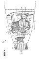
- Fig. 1 shows a front part of a hand tool 2 in the form of a percussion drill.
- This has a fashion switch 4, by means of which both a manual transmission 6 and a recorded in a striking mechanism housing 8 striking mechanism 10 back and forth between different switching stages is switched.
- the fashion switch 4 is designed as a rotary switch.
- a tool spindle 12 on which a tool holder 14 is held, on the one hand driven by the transmission 6 at different rotational speeds about a working axis A around.
- the tool spindle 12 can optionally additionally be acted upon by the percussion mechanism 10 along the working axis A in a recurring manner with a pulse-like striking force S.
- the tool spindle 12 is both rotatable and axially displaceable.
- both gear shift means 16 for actuating the gearbox 6 and percussion switching means 18 for actuating the impact mechanism 10 includes.
- the gear shift means 16 as well as the striking mechanism switching means 18 are coupled in a motion-coupled manner to the mode switch 4.
- the gear shift means 14 are essentially formed by a sliding element 20, via the two opposite end faces S1, S2 of a two-stage gear block 22 of the gearbox 6 can be acted upon with axial pressure.
- the gear block 22 is slidably mounted in the axial direction but rotatably mounted on the tool spindle 12 and can thus be moved back and forth via the sliding element 20 along the working axis A.
- the striking mechanism switching means 18 comprise a pivoting mechanism, which has a switch-side pivot member 24 and a hammer-side pivot member 26.
- the switch-side pivot member 24 in this case comprises a with the fashion switch 4 engaged first pivot arm 28 and is used to actuate the impact mechanism side pivot member 26.
- the impact mechanism side pivot member 26 acts as a means of adjustment by means of which the striking mechanism 10 is switched on and off.
- Fig. 1 shows the fashion switch 6 in a defined by an arrow P1 first rotational position in which the tool spindle 12 is driven at a low speed only and the pivot members 24, 26 are in a passive position in which the striking mechanism 6 is deactivated.
- the mode switch 4 is rotated from this first rotational position in the direction of rotation D in an offset by about 180 ° second rotational position and another 80 to 90 ° in a third rotational position, as indicated by dotted arrows P2 and P3 of the mode switch 4.
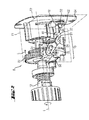
- Fig. 2 shows the switching arrangement 15 in one of the first rotational position of the mode switch 4 corresponding first switching position, wherein the mode switch 4, only a pin-shaped eccentric element 30 is shown.
- This eccentric 30 acts as a coupling means, which is engaged both with a set into the sliding element 20 slide 34 and with a slot 36 which is provided on the first pivot arm 28 of the switch-side pivot member 24 and as well as the gate 34 acts as a negative feedback means.
- the position of the sliding element 20 along the working axis A is determined by the engagement of the eccentric element 30 in the link 34, in which the first switching stage is set on the transmission 6.
- the gear block 22 meshes with a first drive pinion 38 of a drive, not shown.
- the eccentric element 30 sets by its engagement with the slot 36 in this first rotational position of the mode switch 4 a pivot position of the switch-side pivot member 24 fixed.
- a second pivot arm 32 of the switch-side pivot member 24 is directed downward.
- a formed on the second pivot arm 32 by a curved end portion applying element 40 is spaced in this switching position of a driving element 42 of the impact mechanism side pivot member 26 which forms a contact surface 44 which is inclined relative to a first pivot plane E1 of the switch-side pivot member 24 in which Switch-side pivot member 24 is pivotable.
- the impact mechanism-side pivot member 26 is pivotable in a second pivot plane E2, which is substantially perpendicular to the first pivot plane E1 of the switch-side pivot member 24.
- the eccentric element 30 is pivoted in a direction R during rotation of the mode switch 4, wherein the gear block 22 is displaced by means of the sliding element 20 in the direction L and the application element 40 is pivoted in the direction M.
- the second rotational position of the mode switch 4 and a second switching position of the switching device 15 according to Fig. 3 and 4 reached.
- a rear end 48 of the tool spindle 12 can be applied, whereby their displacement is blocked in the axial direction to the rear during operation.
- the impact mechanism-side pivot member 26 is biased by a leg spring 54 in the blocking position in the path of movement P.
- the striking mechanism 10 is designed as a ratchet impact mechanism and has a fixed ratchet wheel 50 which is held fixed in position in the power tool 2 and a movable ratchet wheel 52 on.
- the movable ratchet wheel 52 is fixedly connected to the tool spindle 12 and thus moves with both in the direction of rotation and in the axial direction with this.
- the movable ratchet plate 52 In the illustrated passive position, the movable ratchet plate 52 is held by the voltage applied to the blocking stop 46 rear end 48 of the tool spindle 12 in the axial direction spaced from the fixed ratchet wheel 52. An interaction of the two ratchet discs 50, 52 for acting on the tool spindle 12 with shocks is thus blocked in the second switching position of the switching assembly 15 as well as in the first switching position.
- the mode switch 4 can be further rotated in the direction of rotation D and thus the eccentric element 30 can be further pivoted in the pivoting direction R.
- the switch-side pivot member 24 is pivoted by engagement with the eccentric element 30 such that the second pivot arm 32 presses with the contact element 40 in the direction M against the driving element 42.
- the impact mechanism-side pivot member 26 is pivoted against the force of the spring 54.
- the sliding element 20 and the gear shift means 16 in total remain, however, in the second switching stage.
- the pivoting mechanism formed by the pivoting members 24, 26 is brought into an active position in which the percussion mechanism 10 can be activated.
- the blocking stop 46 is moved completely out of the axial movement path P of the displaceable tool spindle 12, as a result of which its displacement in the axial direction towards the rear during operation is no longer blocked.
- the tool spindle 12 By pressing the hand tool 2 in operation against an object, not shown, to be machined thus the tool spindle 12 can be moved along the axial movement path P.
- the movable ratchet disk 52 which rotates together with the tool spindle 12, comes into recurrent contact with the fixed ratchet disk 50 and thereby acts in a known manner on the tool spindle 12 with recurring impacts along the working axis A.
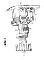
- Fig. 7 shows a gear-side plan view of the switching assembly 15 in the third switching position alone.
- the first pivot bearing D1 between the sliding element 20 and the switch-side pivot member 24 is formed by a pin 56 which projects into a cylindrical receptacle 58.
- the pin 56 is, for example, on the switch-side pivot member 24 taumelgenietet, which is formed as a stamped sheet metal part.
- the cylindrical receptacle 58 is formed by a passage, which is also made together with the rest of the sliding element 20 by bending punching a sheet metal part.
- the impact mechanism side pivot member 26 is formed by a sheet metal stamped punched part.
- the impact mechanism-side pivot member 26 in this case forms a second cylindrical receptacle 60, which forms the second pivot bearing D2 together with a housing-fixed pin 62.
- the housing-fixed pin 62 is formed on a bearing plate 64, in particular from Fig. 2 can be seen.
Abstract
Description
Die Erfindung betrifft ein elektrisches Handwerkzeuggerät mit den Merkmalen gemäss dem Oberbegriff von Patentanspruch 1. Dabei weist das Handwerkzeuggerät ein Schaltgetriebe auf, das wenigstens zwei Schaltstufen umfasst. Ferner weist das Handwerkzeuggerät ein wahlweise zu- und abschaltbares Schlagwerk und einen Modischalter auf, mittels dem sowohl das Schaltgetriebe zwischen den Schaltstufen hin- und her schaltbar als auch das Schlagwerk zu- und abschaltbar ist. Hierzu ist der Modischalter sowohl mit Getriebeschaltmitteln des Schaltgetriebes als auch mit Schlagwerkschaltmitteln des Schlagwerkes bewegungsgekoppelt.The invention relates to an electric hand tool with the features according to the preamble of
Bei derartigen Handwerkzeuggeräten sind sowohl die verschiedenen Getriebeschaltstufen als auch das Schlagwerk über eine einzige Handhabe schaltbar. Dies ermöglicht sowohl eine komfortablere Bedienung als auch eine einfachere Herstellung des Gerätes.In such hand tools both the various gear shift stages and the percussion mechanism can be switched via a single handle. This allows both a more comfortable operation and easier production of the device.
Aus der
Nachteilig an der bekannten Schaltvorrichtung ist, dass die zueinander senkrecht verschiebbaren Schaltelemente einen relativ grossen Bauraum benötigen.A disadvantage of the known switching device is that the vertically displaceable switching elements require a relatively large space.
Der vorliegenden Erfindung liegt die Aufgabe zugrunde, bei einem elektrischen Handwerkzeuggerät die genannten Nachteile zu vermeiden und den benötigten Bauraum zu vermindern.The present invention has for its object to avoid the disadvantages mentioned in an electric hand tool and to reduce the required space.
Erfindungsgemäss wird diese Aufgabe durch ein elektrisches Handwerkzeuggerät mit den Merkmalen von Patentanspruch 1 gelöst, wobei die Schlagwerkschaltmittel einen Schwenkmechanismus aufweisen, der mittels des Modischalters zwischen einer Aktivstellung, in der das Schlagwerk aktivierbar ist, und einer Passivstellung, in der das Schlagwerk deaktiviert ist, verschwenkbar ist. Ein derartiger Schwenkmechanismus kann dabei so ausgebildet sein, dass er in verschiedenen Schaltstellungen wenigstens zum überwiegenden Teil den gleichen Raum einnimmt. Hierdurch ist der für die beweglichen Schlagwerkschaltmittel benötigte Bauraum relativ klein, was wiederum eine kompaktere Bauweise des Handwerkzeuggerätes ermöglicht.According to the invention this object is achieved by an electric hand tool with the features of
In einer besonders bevorzugten Ausführungsform weist der Schwenkmechanismus ein an einem Drehlager verschwenkbar gehaltenes schalterseitiges Schwenkglied auf. Dieses ist mit dem Modischalter bewegungsgekoppelt und betätigt Stellmittel, in Abhängigkeit von deren Position das Schlagwerk ein- und ausschaltbar ist. Durch eine derartige Ausgestaltung des Schwenkgliedes kann ein stabiler Schwenkmechanismus bereitgestellt werden, der das Schlagwerk sicher in einem angewählten Betriebszustand hält.In a particularly preferred embodiment, the swivel mechanism has a switch-side swivel member which is pivotably held on a rotary bearing. This is motion-coupled with the fashion switch and actuates actuating means, depending on their position, the percussion is switched on and off. By such a configuration of the pivot member, a stable pivot mechanism can be provided, which holds the percussion safely in a selected operating condition.
Vorteilhafterweise ist an dem Modischalter ein Exzenterelement vorgesehen, über das sowohl das schalterseitige Schwenkglied als auch die Getriebeschaltmittel betätigbar sind. Hierdurch können die Schaltstellungen des Getriebes direkt mit den Schaltstellungen des Schlagwerkes abgestimmt werden. Auf diese Weise kann beispielsweise sichergestellt werden, dass mit Zuschalten des Schlagwerkes gleichzeitig auch eine hierfür besonders geeignete Drehzahl eingestellt wird.Advantageously, an eccentric element is provided on the fashion switch, via which both the switch-side pivot member and the transmission shifting means can be actuated. As a result, the switching positions of the transmission can be tuned directly with the switching positions of the striking mechanism. In this way, it can be ensured, for example, that at the same time a speed which is particularly suitable for this purpose is set when the percussion mechanism is switched on.
Bevorzugterweise weisen die Stellmittel ein an einem zweiten Drehlager quer zum schalterseitigen Schwenkglied verschwenkbar gehaltenes schlagwerkseitiges Schwenkglied auf. Hierdurch kann die Wirkrichtung der Schlagwerkschaltmittel geändert werden, um das Schlagwerk stabiler beziehungsweise exakter schalten und den benötigten Bauraum weiter reduzieren zu können.Preferably, the adjusting means on a second pivot bearing transversely to the switch-side pivot member pivotally held on the beat mechanism side pivot member. As a result, the direction of action of the striking mechanism switching means can be changed in order to switch the striking mechanism more stably or more accurately and to be able to further reduce the required installation space.
Vorteilhafterweise weist das schlagwerkseitige Schwenkglied einen Blockieranschlag auf, mittels dessen eine erste Ratschenscheibe des Schlagwerkes in der Passivstellung gegenüber einer zweiten Ratschenscheibe beabstandbar ist. Hierdurch ist das Schlagwerk in einer besonders einfachen Weise abschaltbar.Advantageously, the impact mechanism-side pivot member on a blocking stop, by means of which a first ratchet disk of the percussion mechanism in the passive position with respect to a second ratchet wheel is spaced apart. As a result, the striking mechanism can be switched off in a particularly simple manner.
Zudem ist das schlagwerkseitige Schwenkglied vorteilhafterweise durch das schalterseitige Schwenkglied in der Aktivstellung in eine Position verschwenkt, in der die Beabstandung der Ratschenscheiben durch den Blockieranschlag aufgehoben ist. Auf diese Weise ist das Zu-und Abschalten des Schlagwerkes durch eine besonders einfache aber stabile Schaltanordnung möglich.In addition, the impact mechanism-side pivot member is advantageously pivoted by the switch-side pivot member in the active position in a position in which the spacing of the Ratchet discs is lifted by the blocking stop. In this way, the switching on and off of the striking mechanism by a particularly simple but stable switching arrangement is possible.
Dabei ist das schlagwerkseitige Schwenkglied in die Passivstellung vorgespannt, um bei entsprechender Stellung des Modischalters ein ungewolltes Zuschalten des Schlagwerkes ausschliessen zu können.In this case, the impact mechanism-side pivot member is biased in the passive position to exclude an unintentional connection of the percussion mechanism with appropriate position of the fashion switch.
Hierbei ist es günstig, wenn die Vorspannung durch eine Schenkelfeder erzeugt ist. Eine solche Schenkelfeder ist besonders gut an dem schlagwerkseitigen Schwenkglied anbringbar. Hierbei benötigt die Schenkelfeder lediglich einen geringen zusätzlichen Bauraum.It is advantageous if the bias is generated by a leg spring. Such a leg spring is particularly well attachable to the impact mechanism side pivot member. Here, the leg spring needs only a small additional space.
Vorteilhafterweise sind das erste Schwenkglied und das zweite Schwenkglied als Biegestanzteile ausgebildet, wodurch der Schwenkmechanismus kostengünstig herstellbar ist.Advantageously, the first pivot member and the second pivot member are formed as bending punched parts, whereby the pivot mechanism is inexpensive to produce.
Ferner ist es günstig, wenn die Getriebeschaltmittel ein Schiebeelement aufweisen, mittels dem ein Zahnradblock des Schaltgetriebes zwischen den Schaltstufen verschiebbar ist und das als Biegestanzteil ausgebildet ist. Hierdurch ist auch die Betätigung des Schaltgetriebes in besonders einfacher Weise möglich, was wiederum die Herstellungskosten der Schaltanordnung insgesamt vermindert. Zudem benötigt ein solches Schiebeelement lediglich einen geringen zusätzlichen Bauraum.Further, it is advantageous if the gear shift means comprise a sliding element, by means of which a gear block of the gearbox between the switching stages is displaceable and which is designed as a bending punched part. As a result, the operation of the gearbox in a particularly simple manner is possible, which in turn reduces the manufacturing cost of the switching device as a whole. In addition, such a sliding element only requires a small additional space.
Vorteilhafterweise ist zudem das erste Drehlager zwischen dem schalterseitigen Schwenkglied und dem Schiebeelement vorgesehen und durch einen in einen Durchzug greifenden Pin gebildet. Hierbei kann der Durchzug an einem der beiden Biegestanzteile bei dessen Herstellung mit ausgeformt werden und der Pin an dem anderen Biegestanzteil beispielsweise taumelgenietet werden, wodurch das erste Drehlager besonders kostengünstig herstellbar ist.Advantageously, moreover, the first pivot bearing between the switch-side pivot member and the sliding element is provided and formed by a pin engaging in a passage. Here, the passage can be formed at one of the two bending punched parts in its manufacture with and the pin on the other bending punched part, for example, tumble riveted, whereby the first pivot bearing is particularly inexpensive to produce.
Die Erfindung wird nachstehend anhand eines Ausführungsbeispieles näher erläutert. Es zeigen:
- Fig. 1
- eine perspektivische Ansicht einer Schaltanordnung eines erfindungsgemässen Handwerkzeuggerätes,
- Fig. 2
- eine perspektivische Ansicht der Schaltanordnung nach
Fig. 1 bei entferntem Modischalter in einer ersten Schaltstellung, - Fig. 3
- eine perspektivische Ansicht der Schaltanordnung nach
Fig. 2 in einer zweiten Schaltstellung, - Fig. 4
- eine gerade Draufsicht auf die Oberseite der Schaltanordnung nach
Fig. 3 , - Fig. 5
- eine perspektivische Ansicht der Schaltanordnung nach
Fig. 3 in einer dritten Schaltstellung, - Fig. 6
- eine gerade Draufsicht auf die Oberseite der Schaltanordnung nach
Fig. 5 und - Fig. 7
- eine perspektivische Ansicht der Schaltanordnung in Alleinstellung von einer Getriebeseite.
- Fig. 1
- a perspective view of a switching arrangement of an inventive hand tool,
- Fig. 2
- a perspective view of the switching arrangement according to
Fig. 1 when the mode switch is removed in a first switching position, - Fig. 3
- a perspective view of the switching arrangement according to
Fig. 2 in a second switching position, - Fig. 4
- a straight plan view of the top of the switching arrangement according to
Fig. 3 . - Fig. 5
- a perspective view of the switching arrangement according to
Fig. 3 in a third switching position, - Fig. 6
- a straight plan view of the top of the switching arrangement according to
Fig. 5 and - Fig. 7
- a perspective view of the switching arrangement in isolation from a transmission side.
Hierdurch kann eine Werkzeugspindel 12, an der eine Werkzeugaufnahme 14 gehalten ist, einerseits durch das Schaltgetriebe 6 mit unterschiedlichen Drehgeschwindigkeiten um eine Arbeitsachse A herum angetrieben werden. Andererseits kann die Werkzeugspindel 12 wahlweise zusätzlich mittels des Schlagwerkes 10 entlang der Arbeitsachse A wiederkehrend mit einer impulsartigen Schlagkraft S beaufschlagt werden. Hierzu ist die Werkzeugspindel 12 sowohl verdrehbar als auch axial verschiebbar gelagert.In this way, a
Um sowohl das Schaltgetriebe 6 als auch das Schlagwerk 10 mittels des einzigen Modischalters 4 betätigen zu können, ist zwischen diesem, dem Schaltgetriebe 6 und dem Schlagwerk 10 eine insgesamt mit 15 bezeichnete Schaltanordnung vorgesehen, die sowohl Getriebeschaltmittel 16 zur Betätigung des Schaltgetriebes 6 als auch Schlagwerkschaltmittel 18 zur Betätigung des Schlagwerkes 10 umfasst. Die Getriebeschaltmittel 16 wie auch die Schlagwerkschaltmittel 18 sind dabei mit dem Modischalter 4 bewegungsgekoppelt.In order to operate both the
Die Getriebeschaltmittel 14 sind im Wesentlichen durch ein Schiebeelement 20 gebildet, über das zwei voneinander abgewandte Stirnseiten S1, S2 eines zweistufigen Zahnradblockes 22 des Schaltgetriebes 6 mit axialem Druck beaufschlagbar sind. Der Zahnradblock 22 ist dabei in axialer Richtung verschiebbar aber drehfest auf der Werkzeugspindel 12 gelagert und kann somit über das Schiebeelement 20 entlang der Arbeitsachse A hin- und her verschoben werden.The gear shift means 14 are essentially formed by a sliding
Die Schlagwerkschaltmittel 18 umfassen einen Schwenkmechanismus, der ein schalterseitiges Schwenkglied 24 und ein schlagwerkseitiges Schwenkglied 26 aufweist. Das schalterseitige Schwenkglied 24 umfasst dabei einen mit dem Modischalter 4 in Eingriff stehenden ersten Schwenkarm 28 und dient zur Betätigung des schlagwerkseitigen Schwenkgliedes 26. Das schlagwerkseitige Schwenkglied 26 fungiert dabei als Stellmittel, mittels dem das Schlagwerk 10 ein- und ausschaltbar ist.The striking mechanism switching means 18 comprise a pivoting mechanism, which has a switch-
Der Modischalters 4 ist aus dieser ersten Drehstellung in Drehrichtung D in eine um etwa 180° versetzte zweite Drehstellung und um weitere 80 bis 90° in eine dritte Drehstellung verdrehbar, wie durch strichpunktierte Pfeile P2 und P3 des Modischalters 4 angedeutet.The
Wie aus
Gleichzeitig legt das Exzenterelement 30 durch seinen Eingriff mit dem Langloch 36 in dieser ersten Drehstellung des Modischalters 4 eine Schwenkposition des schalterseitigen Schwenkgliedes 24 fest. Dabei ist ein zweiter Schwenkarm 32 des schalterseitigen Schwenkgliedes 24 nach unten gerichtet. Zudem ist ein an dem zweiten Schwenkarm 32 durch einen gebogenen Endabschnitt gebildetes Anlegeelement 40 in dieser Schaltstellung von einem Mitnahmeelement 42 des schlagwerkseitigen Schwenkgliedes 26 beabstandet, das eine Anlegefläche 44 bildet, die gegenüber einer ersten Schwenkebene E1 des schalterseitigen Schwenkgliedes 24 geneigt ist, in der das schalterseitige Schwenkglied 24 verschwenkbar ist. Das schlagwerkseitige Schwenkglied 26 ist dabei in einer zweiten Schwenkebene E2 verschwenkbar, die im Wesentlichen senkrecht zu der ersten Schwenkebene E1 des schalterseitigen Schwenkgliedes 24 steht.At the same time, the
Ausgehend von dieser ersten Drehposition wird beim Verdrehen des Modischalters 4 das Excenterelement 30 in einer Richtung R verschwenkt, wobei der Zahnradblock 22 mittels des Schiebeelementes 20 in Richtung L verschoben und das Anlegeelement 40 in Richtung M verschwenkt wird. Hierbei wird nach einem Verdrehen des Modischalters 4 von etwa 180° die zweite Drehstellung des Modischalters 4 beziehungsweise eine zweite Schaltstellung der Schaltanordnung 15 gemäss
In dieser zweiten Schaltstellung der Schaltanordnung 15 kämmt der Zahnradblock 22 mit einem zweiten Antriebsritzel 45, das mit dem Zahnradblock 22 eine gegenüber der ersten Schaltstufe deutlich grössere Übersetzung bildet, wie insbesondere aus
In dieser Passivstellung ragt ein Teil des schlagwerkseitigen Schwenkgliedes 26, der als Blockieranschlag 46 fungiert, in einen axialen Bewegungspfad P der verschiebbaren Werkzeugspindel 12 (siehe
Wie aus
In der dargestellten Passivstellung wird die bewegliche Ratschenscheibe 52 über das an dem Blockieranschlag 46 anliegende hintere Ende 48 der Werkzeugspindel 12 in axialer Richtung beabstandet zur festen Ratschenscheibe 52 gehalten. Ein Zusammenwirken der beiden Ratschenscheiben 50, 52 zur Beaufschlagung der Werkzeugspindel 12 mit Schlägen ist somit in der zweiten Schaltstellung der Schaltanordnung 15 ebenso wie in der ersten Schaltstellung blockiert.In the illustrated passive position, the movable ratchet plate 52 is held by the voltage applied to the blocking
Ausgehend von dieser zweiten Drehstellung kann der Modischalter 4 in Drehrichtung D weiter verdreht und damit das Excenterelement 30 in Schwenkrichtung R weiter verschwenkt werden. Dabei wird das schalterseitige Schwenkglied 24 durch den Eingriff mit dem Excenterelement 30 derart verschwenkt, dass der zweite Schwenkarm 32 mit dem Anlegeelement 40 in Richtung M gegen das Mitnahmeelement 42 drückt. Dadurch wird das schlagwerkseitige Schwenkglied 26 entgegen der Kraft der Feder 54 verschwenkt. Das Schiebeelement 20 beziehungsweise die Getriebeschaltmittel 16 insgesamt verbleiben dagegen in der zweiten Schaltstufe. Nach einem Verdrehen des Modischalters 4 um etwa 80 bis 90° wird auf diese Weise eine dritte Drehstellung des Modischalters 4 beziehungsweise eine dritte Schaltstellung der Schaltanordnung 15 gemäss
In dieser dritten Schaltstellung der Schaltanordnung 15 ist der, durch die Schwenkglieder 24, 26 gebildete Schwenkmechanismus in eine Aktivstellung verbracht, in der das Schlagwerk 10 aktivierbar ist. Hierzu ist der Blockieranschlag 46 vollständig aus dem axialen Bewegungspfad P der verschiebbaren Werkzeugspindel 12 heraus bewegt, wodurch deren Verschiebung in axialer Richtung nach hinten im Betrieb nicht mehr blockiert wird.In this third switching position of the switching
Durch Anpressen des Handwerkzeuggerätes 2 im Betrieb gegen einen nicht dargestellten zu bearbeitenden Gegenstand kann somit die Werkzeugspindel 12 entlang des axialen Bewegungspfades P bewegt werden. Hierbei kommt die sich zusammen mit der Werkzeugspindel 12 drehende bewegliche Ratschenscheibe 52 in wiederkehrenden Kontakt mit der festen Ratschenscheibe 50 und beaufschlagt dadurch in bekannter Weise die Werkzeugspindel 12 mit wiederkehrenden Schlägen entlang der Arbeitsachse A.By pressing the
Ferner ist auch das schlagwerkseitige Schwenkglied 26 durch ein biegegestanztes Blechteil gebildet. Das schlagwerkseitige Schwenkglied 26 bildet hierbei eine zweite zylindrische Aufnahme 60 aus, die zusammen mit einem gehäusefesten Pin 62 das zweite Drehlager D2 bildet. Der gehäusefeste Pin 62 ist dabei an einem Lagerschild 64 ausgebildet, wie insbesondere aus
Claims (11)
mit einem Schaltgetriebe (6), das wenigstens zwei Schaltstufen aufweist,
einem zuschaltbaren Schlagwerk (10) und
einem Modischalter (4), mittels dem sowohl das Schaltgetriebe (6) zwischen den Schaltstufen hin- und her schaltbar als auch das Schlagwerk (10) zu- und abschaltbar ist, und
der hierzu sowohl mit Getriebeschaltmitteln (16) des Schaltgetriebes (6) als auch mit Schlagwerkschaltmitteln (18) des Schlagwerkes (10) bewegungsgekoppelt ist,
dadurch gekennzeichnet, dass die Schlagwerkschaltmittel (18) einen Schwenkmechanismus aufweisen, der mittels des Modischalters (4) zwischen einer Aktivstellung, in der das Schlagwerk (10) aktivierbar ist, und einer Passivstellung, in der das Schlagwerk (10) deaktiviert ist, verschwenkbar ist.Electric Hand Tool (2)
with a gearbox (6) having at least two switching stages,
a switchable percussion (10) and
a mode switch (4), by means of which both the manual transmission (6) between the switching stages and forth switchable and the impact mechanism (10) switched on and off, and
for this purpose both with gear shift means (16) of the gearbox (6) and with Schlagwerkschaltmitteln (18) of the percussion mechanism (10) is motion-coupled,
characterized in that the Schlagwerkschaltmittel (18) have a pivoting mechanism which by means of the mode switch (4) between an active position in which the striking mechanism (10) is activated, and a passive position in which the impact mechanism (10) is deactivated, is pivotable ,
Applications Claiming Priority (1)
| Application Number | Priority Date | Filing Date | Title |
|---|---|---|---|
| DE102006000515A DE102006000515A1 (en) | 2006-12-12 | 2006-12-12 | Electric hand tool |
Publications (3)
| Publication Number | Publication Date |
|---|---|
| EP1932625A2 true EP1932625A2 (en) | 2008-06-18 |
| EP1932625A3 EP1932625A3 (en) | 2008-08-27 |
| EP1932625B1 EP1932625B1 (en) | 2010-08-04 |
Family
ID=39183115
Family Applications (1)
| Application Number | Title | Priority Date | Filing Date |
|---|---|---|---|
| EP07122207A Active EP1932625B1 (en) | 2006-12-12 | 2007-12-04 | Electric hand tool device |
Country Status (6)
| Country | Link |
|---|---|
| US (1) | US7607493B2 (en) |
| EP (1) | EP1932625B1 (en) |
| JP (1) | JP5201972B2 (en) |
| CN (1) | CN101200061B (en) |
| DE (2) | DE102006000515A1 (en) |
| ES (1) | ES2349807T3 (en) |
Cited By (5)
| Publication number | Priority date | Publication date | Assignee | Title |
|---|---|---|---|---|
| FR2993193A1 (en) * | 2012-07-16 | 2014-01-17 | Bosch Gmbh Robert | Switching unit for switching transmission unit between two switching positions in puncher, has transmission element coupled to switching element, where transmission element slides portion of transmission unit between two switching positions |
| WO2017102532A1 (en) * | 2015-12-18 | 2017-06-22 | Robert Bosch Gmbh | Hand-held power tool comprising a communication interface |
| US9873192B2 (en) | 2013-12-11 | 2018-01-23 | Black & Decker Inc. | Rotary hammer |
| US10046450B2 (en) | 2014-07-28 | 2018-08-14 | Black & Decker Inc. | Mode change knob assembly |
| US10994403B2 (en) | 2015-12-18 | 2021-05-04 | Robert Bosch Gmbh | Hand-held power tool comprising a gearshift unit |
Families Citing this family (27)
| Publication number | Priority date | Publication date | Assignee | Title |
|---|---|---|---|---|
| FR2907695B1 (en) * | 2006-10-27 | 2009-06-26 | Cooper Power Tools Sas Soc Par | METHOD FOR DRILLING A BORING AND CORRESPONDING MACHINE |
| DE102006059076A1 (en) * | 2006-12-14 | 2008-06-19 | Robert Bosch Gmbh | Schlagwerk an electric hand tool machine |
| US7798245B2 (en) * | 2007-11-21 | 2010-09-21 | Black & Decker Inc. | Multi-mode drill with an electronic switching arrangement |
| US20100111626A1 (en) * | 2008-10-31 | 2010-05-06 | Cooper Industries | Cushion mechanism for a positive peck feed drill |
| US8172004B2 (en) | 2009-08-05 | 2012-05-08 | Techtronic Power Tools Technology Limited | Automatic transmission for a power tool |
| CN101758486B (en) * | 2010-01-21 | 2011-09-28 | 浙江海王电器有限公司 | Light single-button multifunctional electric hammer |
| US8714888B2 (en) * | 2010-10-25 | 2014-05-06 | Black & Decker Inc. | Power tool transmission |
| KR101059687B1 (en) * | 2011-01-28 | 2011-08-25 | 계양전기 주식회사 | Power tool providing hammer and drill function |
| CN102794751B (en) * | 2011-05-23 | 2017-02-01 | 博世电动工具(中国)有限公司 | Electric tool and transmission switching mechanism thereof |
| DE102012202278A1 (en) | 2012-02-15 | 2013-08-22 | Hilti Aktiengesellschaft | Hand tool |
| DE102012214938B4 (en) * | 2012-08-22 | 2016-11-10 | Metabowerke Gmbh | Gear arrangement for a driven machine tool and machine tool with such a gear arrangement |
| US9108312B2 (en) | 2012-09-11 | 2015-08-18 | Milwaukee Electric Tool Corporation | Multi-stage transmission for a power tool |
| CN204686830U (en) | 2012-10-19 | 2015-10-07 | 米沃奇电动工具公司 | Hammer drill |
| CN103894983A (en) * | 2012-12-26 | 2014-07-02 | 株式会社牧田 | Hammer drill |
| EP2832390A1 (en) * | 2013-07-30 | 2015-02-04 | Sensile Pat AG | Drug delivery device with needle actuation mechanism |
| EP2842697A1 (en) * | 2013-09-02 | 2015-03-04 | HILTI Aktiengesellschaft | Manual tool machine |
| US10328560B2 (en) * | 2015-02-23 | 2019-06-25 | Brian Romagnoli | Multi-mode drive mechanisms and tools incorporating the same |
| WO2016196979A1 (en) | 2015-06-05 | 2016-12-08 | Ingersoll-Rand Company | Impact tools with ring gear alignment features |
| WO2016196899A1 (en) | 2015-06-05 | 2016-12-08 | Ingersoll-Rand Company | Power tool housings |
| WO2016196891A1 (en) * | 2015-06-05 | 2016-12-08 | Ingersoll-Rand Company | Power tool user interfaces |
| WO2016196984A1 (en) | 2015-06-05 | 2016-12-08 | Ingersoll-Rand Company | Power tools with user-selectable operational modes |
| US10615670B2 (en) | 2015-06-05 | 2020-04-07 | Ingersoll-Rand Industrial U.S., Inc. | Power tool user interfaces |
| WO2018062609A1 (en) | 2016-09-28 | 2018-04-05 | 계양전기 주식회사 | Tool assembly for electric power tool and electric power tool comprising same |
| DE102017121717A1 (en) * | 2017-09-19 | 2019-03-21 | Metabowerke Gmbh | Actuator and gear assembly for a power tool |
| US11320320B2 (en) * | 2018-07-25 | 2022-05-03 | Texas Instruments Incorporated | Temperature sensor circuit for relative thermal sensing |
| EP3808478B1 (en) * | 2019-10-14 | 2022-04-06 | Nanjing Chervon Industry Co., Ltd. | Impact drill |
| CN117123658B (en) * | 2023-10-20 | 2024-01-02 | 山西建筑工程集团有限公司 | Portable automatic bending machine for handheld metal conduit |
Citations (1)
| Publication number | Priority date | Publication date | Assignee | Title |
|---|---|---|---|---|
| DE102004057686A1 (en) | 2004-11-30 | 2006-06-01 | Robert Bosch Gmbh | switching device |
Family Cites Families (14)
| Publication number | Priority date | Publication date | Assignee | Title |
|---|---|---|---|---|
| DE1957235C3 (en) * | 1969-11-14 | 1974-04-25 | Robert Bosch Gmbh, 7000 Stuttgart | Motor-driven hammer drill |
| US3934688A (en) * | 1974-09-11 | 1976-01-27 | The Black And Decker Manufacturing Company | Shifter mechanism |
| NL8304043A (en) * | 1983-11-24 | 1985-06-17 | Skil Nederland Nv | DEVICE FOR DRIVING A DRILL AND / OR IMPACT TOOL. |
| DE3807078A1 (en) * | 1988-03-04 | 1989-09-14 | Black & Decker Inc | DRILLING HAMMER |
| DE4013512A1 (en) * | 1990-04-27 | 1991-10-31 | Black & Decker Inc | SWITCHING DEVICE FOR SWITCHING A POWERED TOOL |
| JPH04105809A (en) * | 1990-08-28 | 1992-04-07 | Matsushita Electric Works Ltd | Vibration drill |
| DE4121279A1 (en) * | 1991-06-27 | 1993-01-07 | Bosch Gmbh Robert | DRILL AND / OR SLOPE |
| DE4213291C2 (en) * | 1992-04-23 | 1997-12-04 | Atlas Copco Elektrowerkzeuge | Gear device of a hand-held rotary hammer machine |
| DE19528924B4 (en) * | 1995-08-05 | 2005-01-27 | Scintilla Ag | Electric hammer drill |
| GB9621202D0 (en) * | 1996-10-11 | 1996-11-27 | Black & Decker Inc | Mode change switch |
| US6223833B1 (en) * | 1999-06-03 | 2001-05-01 | One World Technologies, Inc. | Spindle lock and chipping mechanism for hammer drill |
| DE19955412A1 (en) * | 1999-11-18 | 2001-05-23 | Hilti Ag | Drilling and chiseling device |
| DE10031050A1 (en) * | 2000-06-26 | 2002-01-10 | Hilti Ag | Hand tool |
| JP3936146B2 (en) * | 2001-03-02 | 2007-06-27 | 株式会社マキタ | Vibration drill |
-
2006
- 2006-12-12 DE DE102006000515A patent/DE102006000515A1/en not_active Withdrawn
-
2007
- 2007-12-04 EP EP07122207A patent/EP1932625B1/en active Active
- 2007-12-04 ES ES07122207T patent/ES2349807T3/en active Active
- 2007-12-04 DE DE502007004630T patent/DE502007004630D1/en active Active
- 2007-12-10 US US12/001,255 patent/US7607493B2/en active Active
- 2007-12-11 CN CN2007101996113A patent/CN101200061B/en active Active
- 2007-12-11 JP JP2007320096A patent/JP5201972B2/en active Active
Patent Citations (1)
| Publication number | Priority date | Publication date | Assignee | Title |
|---|---|---|---|---|
| DE102004057686A1 (en) | 2004-11-30 | 2006-06-01 | Robert Bosch Gmbh | switching device |
Cited By (7)
| Publication number | Priority date | Publication date | Assignee | Title |
|---|---|---|---|---|
| FR2993193A1 (en) * | 2012-07-16 | 2014-01-17 | Bosch Gmbh Robert | Switching unit for switching transmission unit between two switching positions in puncher, has transmission element coupled to switching element, where transmission element slides portion of transmission unit between two switching positions |
| RU2659504C2 (en) * | 2012-07-16 | 2018-07-02 | Роберт Бош Гмбх | Switching mechanism |
| US9873192B2 (en) | 2013-12-11 | 2018-01-23 | Black & Decker Inc. | Rotary hammer |
| US10046450B2 (en) | 2014-07-28 | 2018-08-14 | Black & Decker Inc. | Mode change knob assembly |
| WO2017102532A1 (en) * | 2015-12-18 | 2017-06-22 | Robert Bosch Gmbh | Hand-held power tool comprising a communication interface |
| US10994403B2 (en) | 2015-12-18 | 2021-05-04 | Robert Bosch Gmbh | Hand-held power tool comprising a gearshift unit |
| US11529726B2 (en) | 2015-12-18 | 2022-12-20 | Robert Bosch Gmbh | Hand-held power tool comprising a communication interface |
Also Published As
| Publication number | Publication date |
|---|---|
| DE102006000515A1 (en) | 2008-06-19 |
| CN101200061B (en) | 2011-12-07 |
| EP1932625A3 (en) | 2008-08-27 |
| EP1932625B1 (en) | 2010-08-04 |
| JP5201972B2 (en) | 2013-06-05 |
| DE502007004630D1 (en) | 2010-09-16 |
| CN101200061A (en) | 2008-06-18 |
| ES2349807T3 (en) | 2011-01-11 |
| US20080223592A1 (en) | 2008-09-18 |
| JP2008142889A (en) | 2008-06-26 |
| US7607493B2 (en) | 2009-10-27 |
Similar Documents
| Publication | Publication Date | Title |
|---|---|---|
| EP1932625B1 (en) | Electric hand tool device | |
| DE60120006T2 (en) | Electric hand tool | |
| DE602005004980T2 (en) | Power tool with operating mode selector switch for selecting one of several operating modes | |
| EP1578564B1 (en) | Drill hammer | |
| EP2129496B1 (en) | Hand machine tool | |
| EP1864761A1 (en) | Manual tool with vibration reduction device | |
| WO2005110651A1 (en) | Universal saw | |
| DE102014210344A1 (en) | Hand tool with a switchable gearbox | |
| DE102004045117A1 (en) | switching device | |
| EP2755804A1 (en) | Motor-driven machine tool | |
| EP2305434B1 (en) | Electric power tool | |
| EP1563956A1 (en) | Driving device | |
| EP1506846B1 (en) | Portable power tool | |
| DE102006061600A1 (en) | Electric hand tool, has planetary gear arranged between spindle and shaft, transmissions switchable by switching unit, and driving device switched on and off by another switching unit, where switching units are actuatable by common switch | |
| EP0239670B1 (en) | Motor-driven machine with torque adjustment, in particular an electrical hand tool | |
| DE102011086919A1 (en) | Electric hand tool | |
| EP2655018A1 (en) | Portable power tool | |
| DE202017102057U1 (en) | Switchable multifunctional electric hammer between different operating modes | |
| CH696919A5 (en) | Device switch of an electric hand tool. | |
| EP1913615B1 (en) | Tensioning apparatus | |
| DE102014110883A1 (en) | Handle for a medical instrument with a latching mechanism | |
| EP1834736A1 (en) | Hand power tool | |
| EP0700595A1 (en) | Hand-held electrical power tool with a potentiometer, and a method for adjusting the potentiometer | |
| EP0510660B1 (en) | Handtool | |
| EP1541292B1 (en) | Rotary hammer |
Legal Events
| Date | Code | Title | Description |
|---|---|---|---|
| PUAI | Public reference made under article 153(3) epc to a published international application that has entered the european phase |
Free format text: ORIGINAL CODE: 0009012 |
|
| AK | Designated contracting states |
Kind code of ref document: A2 Designated state(s): AT BE BG CH CY CZ DE DK EE ES FI FR GB GR HU IE IS IT LI LT LU LV MC MT NL PL PT RO SE SI SK TR |
|
| AX | Request for extension of the european patent |
Extension state: AL BA HR MK RS |
|
| PUAL | Search report despatched |
Free format text: ORIGINAL CODE: 0009013 |
|
| AK | Designated contracting states |
Kind code of ref document: A3 Designated state(s): AT BE BG CH CY CZ DE DK EE ES FI FR GB GR HU IE IS IT LI LT LU LV MC MT NL PL PT RO SE SI SK TR |
|
| AX | Request for extension of the european patent |
Extension state: AL BA HR MK RS |
|
| 17P | Request for examination filed |
Effective date: 20090227 |
|
| AKX | Designation fees paid |
Designated state(s): CH DE ES FR GB IT LI |
|
| GRAP | Despatch of communication of intention to grant a patent |
Free format text: ORIGINAL CODE: EPIDOSNIGR1 |
|
| GRAS | Grant fee paid |
Free format text: ORIGINAL CODE: EPIDOSNIGR3 |
|
| GRAA | (expected) grant |
Free format text: ORIGINAL CODE: 0009210 |
|
| AK | Designated contracting states |
Kind code of ref document: B1 Designated state(s): CH DE ES FR GB IT LI |
|
| REG | Reference to a national code |
Ref country code: GB Ref legal event code: FG4D Free format text: NOT ENGLISH |
|
| REG | Reference to a national code |
Ref country code: CH Ref legal event code: EP |
|
| REF | Corresponds to: |
Ref document number: 502007004630 Country of ref document: DE Date of ref document: 20100916 Kind code of ref document: P |
|
| REG | Reference to a national code |
Ref country code: ES Ref legal event code: FG2A Effective date: 20101228 |
|
| PLBE | No opposition filed within time limit |
Free format text: ORIGINAL CODE: 0009261 |
|
| STAA | Information on the status of an ep patent application or granted ep patent |
Free format text: STATUS: NO OPPOSITION FILED WITHIN TIME LIMIT |
|
| 26N | No opposition filed |
Effective date: 20110506 |
|
| REG | Reference to a national code |
Ref country code: DE Ref legal event code: R097 Ref document number: 502007004630 Country of ref document: DE Effective date: 20110506 |
|
| PG25 | Lapsed in a contracting state [announced via postgrant information from national office to epo] |
Ref country code: IT Free format text: LAPSE BECAUSE OF NON-PAYMENT OF DUE FEES Effective date: 20101204 |
|
| REG | Reference to a national code |
Ref country code: FR Ref legal event code: PLFP Year of fee payment: 9 |
|
| REG | Reference to a national code |
Ref country code: FR Ref legal event code: PLFP Year of fee payment: 10 |
|
| REG | Reference to a national code |
Ref country code: FR Ref legal event code: PLFP Year of fee payment: 11 |
|
| PGFP | Annual fee paid to national office [announced via postgrant information from national office to epo] |
Ref country code: IT Payment date: 20191230 Year of fee payment: 13 |
|
| PGFP | Annual fee paid to national office [announced via postgrant information from national office to epo] |
Ref country code: ES Payment date: 20200121 Year of fee payment: 13 |
|
| PG25 | Lapsed in a contracting state [announced via postgrant information from national office to epo] |
Ref country code: IT Free format text: LAPSE BECAUSE OF NON-PAYMENT OF DUE FEES Effective date: 20201204 |
|
| REG | Reference to a national code |
Ref country code: ES Ref legal event code: FD2A Effective date: 20220208 |
|
| PG25 | Lapsed in a contracting state [announced via postgrant information from national office to epo] |
Ref country code: ES Free format text: LAPSE BECAUSE OF NON-PAYMENT OF DUE FEES Effective date: 20201205 |
|
| PGFP | Annual fee paid to national office [announced via postgrant information from national office to epo] |
Ref country code: CH Payment date: 20221213 Year of fee payment: 16 |
|
| PGFP | Annual fee paid to national office [announced via postgrant information from national office to epo] |
Ref country code: GB Payment date: 20231220 Year of fee payment: 17 |
|
| PGFP | Annual fee paid to national office [announced via postgrant information from national office to epo] |
Ref country code: FR Payment date: 20231221 Year of fee payment: 17 Ref country code: DE Payment date: 20231214 Year of fee payment: 17 |