EP1932413A1 - Vorrichtung zum optischen Zählen kleiner Körperchen - Google Patents
Vorrichtung zum optischen Zählen kleiner Körperchen Download PDFInfo
- Publication number
- EP1932413A1 EP1932413A1 EP07023623A EP07023623A EP1932413A1 EP 1932413 A1 EP1932413 A1 EP 1932413A1 EP 07023623 A EP07023623 A EP 07023623A EP 07023623 A EP07023623 A EP 07023623A EP 1932413 A1 EP1932413 A1 EP 1932413A1
- Authority
- EP
- European Patent Office
- Prior art keywords
- separation point
- measuring space
- measuring
- conveying line
- discs
- Prior art date
- Legal status (The legal status is an assumption and is not a legal conclusion. Google has not performed a legal analysis and makes no representation as to the accuracy of the status listed.)
- Granted
Links
Images


Classifications
-
- A—HUMAN NECESSITIES
- A01—AGRICULTURE; FORESTRY; ANIMAL HUSBANDRY; HUNTING; TRAPPING; FISHING
- A01C—PLANTING; SOWING; FERTILISING
- A01C7/00—Sowing
- A01C7/08—Broadcast seeders; Seeders depositing seeds in rows
- A01C7/10—Devices for adjusting the seed-box ; Regulation of machines for depositing quantities at intervals
- A01C7/102—Regulating or controlling the seed rate
- A01C7/105—Seed sensors
Definitions
- the invention relates to a device for optical counting of small particles.
- Such devices are known. These devices are also referred to as grain counters and used for counting seeds in agricultural seed drills.
- the measuring space of these grain counters is formed by translucent discs, behind which light emitters and light detectors of the sensors are arranged. Due to air turbulence, particles located in the conveying air flow accumulate on the transparent disks. As a result, they foul, so that the beam path, which is generated by the light emitters and is directed to the light detectors is obstructed, so that no reliable measurements can be performed.
- the invention has for its object to ensure reliable detection of the body to be counted.
- the Separation point between the housing of the measuring chamber and the delivery line is arranged.
- An advantageous arrangement of the separation point in the conveying line to achieve the translucent discs for their cleaning is achieved in that the separation point seen in the conveying direction is located behind the measuring space and / or the transparent discs in the conveying line.
- the seeder is designed as a pneumatic distributor. It has a frame 1 and reservoir 2.
- the frame 1 is supported on wheels 3 or a bottom roller on the ground.
- the reservoir 2 is assigned a central metering 4, which in the reservoir 2 seed via a lock 5 in a central supply line 6, which is designed as a riser, initiates.
- This riser pipe 6 opens at its upper end in a distributor head 7, via which the metered seed is divided between the individual seed lines 8 adjoining the distributor head.
- the seed lines 8 lead to the frame 1 hinged coulters 9.
- the impeller 3 is associated with a distance measuring device that transmits measurement data to an on-board computer 10 designed electronic evaluation.
- the doser 4 is driven by a power train via a drive train and an adjustable gear 11.
- the transmission 11 is adjusted via a setting motor 12 and controlled by the on-board computer 10.
- At least one of the seed lines 8 is associated with a device 13 for optical counting of small particles, which is designed as a grain counting sensor 13.
- the sensor 13 is arranged in the seed line 8 and has the housing 14. In the housing 14 is a measuring chamber 15, which pass through the funded in the conveyor line 8 seed 16.
- the sensor 13 has at least one light emitter 17 and at least one light detector 18, wherein the light detector 18 is designed as a CCD line or line scan camera.
- the light emitter 17 is formed as a laser light source.
- the respective laser light source 17 is a laser light beam 19 wide fanning and parallel light beams 20 generating lens 21 is arranged.
- the sensor 13 has two light detectors 18 and light emitter 17 offset by 90 °.
- the light emitters 17 and light detectors 18 of the sensors 13 are arranged at a distance from the contour of the walls 22 of the measuring space 15.
- the walls 22 of the measuring space are formed as translucent discs 23.
- the light emitter 17 and light detectors 18 of Sensors 13 are sealed behind spaced apart from the translucent sealing washer 23.
- the measuring chamber 15 of the sensor 13 is located between two transition funnels 24 and 25 which are arranged in the conveying line 8.
- the measuring chamber 15 In the adjoining region of the transition funnels 24, 25 is the measuring chamber 15, whose walls 22 are formed by the transparent discs 23.
- the translucent disks 23 are sealingly arranged in a housing 15 having the measuring chamber 15, in which the transition funnels 24, 25 are located.
- the seed grains 16 flow through the measuring space 15 in the direction of arrow 26.
- the adjoining the measuring space 15 in the direction of arrow 8 area of the line 8 is fastened by means of the union nut 27 on the housing 14.
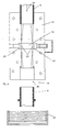
- the union nut 27 can be seen in the embodiment of, seen in the direction of arrow 26, behind the measuring chamber 15 located part of the line 8 are removed from the housing 14, such as Fig. 4 shows, so that a separation point 28 is formed in the line 8 behind the measuring chamber 15.
- a cleaning opening 29 is provided so that through the separation point 28, the discs 23 of the measuring chamber 15 on its measuring chamber side 23 'to clean.
- the separation point 28 is located between the housing 14 of the measuring chamber 15 and the delivery line 8, such as Fig. 3 and 4 demonstrate.
- the separation point 28 is seen in the conveying direction 26, arranged behind the measuring space 15 and the transparent discs 23 in the conveying line 8.
- the union nut 27 is removed, so that the delivery line 8 is removed from the housing.
- This separation point 28 creates a Opening 29 through which the discs 23, as already stated, are to be cleaned by means of a suitable object, cleaning agent or cleaning device.
- the delivery line 8 is again inserted into the housing 14 and secured to the housing 14 with the union nut 27.
- the Ausbringarbeit can be continued in the usual way.
Landscapes
- Life Sciences & Earth Sciences (AREA)
- Soil Sciences (AREA)
- Environmental Sciences (AREA)
- Sowing (AREA)
- Automatic Analysis And Handling Materials Therefor (AREA)
- Investigating Or Analysing Biological Materials (AREA)
- Pretreatment Of Seeds And Plants (AREA)
Abstract
Description
- Die Erfindung betrifft eine Vorrichtung zum optischen Zählen kleiner Körperchen.
- Derartige Vorrichtungen sind bekannt. Diese Vorrichtungen werden auch als Körnerzähler bezeichnet und zum Zählen von Saatkörnern bei landwirtschaftlichen Sämaschinen eingesetzt. Der Messraum dieser Körnerzähler wird von lichtdurchlässigen Scheiben gebildet, hinter denen Lichtemitter und Lichtdetektoren der Sensoren angeordnet sind. Aufgrund von Luftverwirbelungen lagern sich im Förderluftstrom befindliche Partikel am den lichtdurchlässigen Scheiben an. Hierdurch verschmutzen diese, so dass der Strahlengang, der von den Lichtemittern erzeugt wird und auf die Lichtdetektoren gerichtet ist, behindert wird, so dass keine zuverlässigen Messungen durchgeführt werden können.
- Der Erfindung liegt die Aufgabe zugrunde, eine zuverlässige Erfassung der zu zählenden Körperchen zu gewährleisten.
- Diese Aufgabe wird erfindungsgemäß durch die kennzeichnenden Merkmale des Patentanspruches 1 gelöst. Infolge dieser Maßnahmen kann durch die Trennstelle eine Reinigungsöffnung geschaffen werden, so dass durch die Reinigungsöffnung die Scheiben mit einer geeigneten Vorrichtung von Zeit zu Zeit zu reinigen sind. Hierdurch ist gewährleistet, dass eine zuverlässige Erfassung aufgrund des zumindest annähernd störungsfreien Durchdringung des von den Lichtemittern erzeugten Strahlengangs zu den Detektoren zu zählenden Körperchen durch die lichtdurchlässigen hindurch erfolgen kann.
- Um die Möglichkeit zu schaffen, dass in einfacher Weise der Messraum gereinigt werden kann, ist vorgesehen, dass die Trennstelle zwischen dem Gehäuse des Messraumes und der Förderleitung angeordnet ist.
- Eine vorteilhafte Anordnung der Trennstelle in der Förderleitung zur Erreichung der lichtdurchlässigen Scheiben zu deren Reinigung wird dadurch erreicht, dass die Trennstelle in Förderrichtung gesehen sich hinter dem Messraum und/oder den lichtdurchlässigen Scheiben in der Förderleitung befindet.
- Weitere Einzelheiten der Erfindung sind der Beispielsbeschreibung und den Zeichnungen zu entnehmen. Hierbei zeigen
- Fig. 1
- eine erfindungsgemäß ausgestattete Sämaschine in Prinzipdarstellung,
- Fig. 2
- die Anordnung des Sensors zum Zählen kleiner Körperchen in Prinzipdarstellung,
- Fig. 3
- die Verteilerleitung mit dem erfindungsgemäßen Messraum des Sensors mit der Trennstelle im Schnitt und vergrößerter Darstellung und in Prinzipdarstellung und
- Fig. 4
- die an der Trennstelle getrennte Verteilerleitung mit Messraum und Sensor in der Darstellungsweise entsprechend
Fig. 3 . - Die Sämaschine ist als pneumatische Verteilmaschine ausgebildet. Sie weist einen Rahmen 1 und Vorratsbehälter 2 auf. Der Rahmen 1 stützt sich auf Laufrädern 3 oder einer Bodenwalze auf dem Boden ab. Dem Vorratsbehälter 2 ist ein Zentraldosierer 4 zugeordnet, der das sich im Vorratsbehälter 2 befindliche Saatgut über eine Schleuse 5 in eine zentrale Zuführleitung 6, die als Steigrohr ausgebildet ist, einleitet. Dieses Steigrohr 6 mündet an seinem oberen Ende in einem Verteilerkopf 7, über den das dosierte Saatgut auf die einzelnen sich an dem Verteilerkopf anschließenden Saatleitungen 8 aufgeteilt wird. Die Saatleitungen 8 führen zu den am Rahmen 1 angelenkten Säscharen 9. Dem Laufrad 3 ist eine Wegstreckenmesseinrichtung zugeordnet, die Messdaten an eine als Bordcomputer 10 ausgebildete elektronische Auswerteeinheit übermittelt. Der Dosierer 4 wird über einen Antriebsstrang und ein einstellbares Getriebe 11 von einer Kraftquelle angetrieben. Das Getriebe 11 wird über einen Einstellmotor 12 eingestellt und von dem Bordcomputer 10 angesteuert.
- Zumindest einer der Saatleitungen 8 ist eine Vorrichtung 13 zum optischen Zählen kleiner Körperchen, die als Körnerzählsensor 13 ausgebildet ist, zugeordnet. Der Sensor 13 ist in der Saatleitung 8 angeordnet und weist das Gehäuse 14 auf. In dem Gehäuse 14 befindet sich ein Messraum 15, den die in der Förderleitung 8 geförderten Saatkörner 16 passieren. Der Sensor 13 weist zumindest einen Lichtemitter 17 und zumindest einen Lichtdetektor 18 auf, wobei der Lichtdetektor 18 als CCD-Zeile oder Zeilenkamera ausgebildet ist. Der Lichtemitter 17 ist als Laserlichtquelle ausgebildet. Hierbei ist der jeweiligen Laserlichtquelle 17 eine den Laserlichtstrahl 19 breit auffächernde und parallele Lichtstrahlen 20 erzeugende Linse 21 angeordnet. Insgesamt weist der Sensor 13 zwei um 90° versetzt Lichtdetektoren 18 und Lichtemitter 17 auf. Die Lichtemitter 17 und Lichtdetektoren 18 der Sensoren 13 sind beabstandet zu der Kontur der Wände 22 des Messraumes 15 angeordnet. Die Wände 22 des Messraumes sich als lichtdurchlässige Scheiben 23 ausgebildet. Die Lichtemitter 17 und Lichtdetektoren 18 der Sensoren 13 sind abgedichtet hinter beabstandet zu dem lichtdurchlässigen Dichtungsscheiben 23 angeordnet.
- Der Messraum 15 des Sensors 13 befindet sich zwischen zwei Übergangstrichtern 24 und 25 die in der Förderleitung 8 angeordnet sind. In dem einander anschließenden Bereich der Übergangstrichter 24, 25 befindet sich der Messraum 15, dessen Wände 22 von den lichtdurchlässigen Scheiben 23 gebildet werden. Die lichtdurchlässigen Scheiben 23 sind abdichtend in einem den Messraum 15 aufweisenden Gehäuse 14, in welchem die Übergangstrichter 24, 25 befinden angeordnet. Die Saatkörner 16 durchströmen den Messraum 15 in Pfeilrichtung 26.
- Der in Pfeilrichtung 8 an den Messraum 15 anschließende Bereich der Leitung 8 wird mittels der Überwurfmutter 27 an dem Gehäuse 14 befestigt. Durch die Überwurfmutter 27 kann im Ausführungsbeispiel der, in Pfeilrichtung 26 gesehen, hinter dem Messraum 15 sich befindende Teil der Leitung 8 von dem Gehäuse 14 abgenommen werden, wie
Fig. 4 zeigt, so dass eine Trennstelle 28 in der Leitung 8 hinter dem Messraum 15 entsteht. Über diese Trennstelle 28 wird eine Reinigungsöffnung 29 geschaffen, so dass durch die Trennstelle 28 die Scheiben 23 des Messraumes 15 auf ihrer Messraumseite 23' zu reinigen ist. Die Trennstelle 28 befindet sich zwischen dem Gehäuse 14 des Messraumes 15 und der Förderleitung 8, wieFig. 3 und4 zeigen. Des weiteren ist die Trennstelle 28 in Förderrichtung 26 gesehen, hinter dem Messraum 15 und dem lichtdurchlässigen Scheiben 23 in der Förderleitung 8 angeordnet. - Um die Scheiben 23 zu reinigen wird die Überwurfmutter 27 abgenommen, so dass die Förderleitung 8 von dem Gehäuse abgenommen wird. Über diese Trennstelle 28 entsteht eine Öffnung 29 durch welche die Scheiben 23, wie vor bereits gesagt, mittels eines geeigneten Gegenstandes, Reinigungsmittels oder Reinigungsvorrichtung zu reinigen sind. Nach dem Reinigen der Messscheiben 23 auf der Messraumseite 23' wird die Förderleitung 8 wieder in das Gehäuse 14 eingesteckt und mit der Überwurfmutter 27 an dem Gehäuse 14 gesichert. Anschließend kann die Ausbringarbeit in gewohnter Weise fortgesetzt werden.
Claims (3)
- Vorrichtung zum optischen Zählen kleiner Körperchen, insbesondere die von einer Sämaschine auszubringenden Saatkörner, bei denen die zu zählenden Körper einen mit optischen Sensoren besetzten und in einer Förderleitung angeordneten Messraum passieren und dabei den Lichtgang zwischen einem Lichtemitter und einem Lichtdetektor der Sensoren unterbrechen, wobei die Förderleitung vor und hinter dem Messraum einen kreisrunden Querschnitt aufweist, wobei der Messraum einen rechteckigen, vorzugsweise quadratischen Querschnitt aufweist, wobei die Wände des Messraumes von lichtdurchlässigen und planen und/oder ebenen Scheiben gebildet werden, dadurch gekennzeichnet, dass die Vorrichtung eine Trennstelle (28) zur Schaffung einer Reinigungsöffnung (29) aufweist, dass durch die Trennstelle (28) die Scheiben auf ihrer Messraumseite (23') zu reinigen sind.
- Vorrichtung nach Anspruch 1, dadurch gekennzeichnet, dass die Trennstelle (28) zwischen dem Gehäuse (14) des Messraumes (15) und der Förderleitung (8) angeordnet ist.
- Vorrichtung nach Anspruch 1, dadurch gekennzeichnet, dass die Trennstelle (28) in Förderrichtung (26) gesehen sich hinter dem Messraum (15) und/oder den lichtdurchlässigen Scheiben (23) in der Förderleitung (8) befindet.
Applications Claiming Priority (1)
| Application Number | Priority Date | Filing Date | Title |
|---|---|---|---|
| DE102006058687A DE102006058687A1 (de) | 2006-12-13 | 2006-12-13 | Vorrichtung zum optischen Zählen kleiner Körperchen |
Publications (2)
| Publication Number | Publication Date |
|---|---|
| EP1932413A1 true EP1932413A1 (de) | 2008-06-18 |
| EP1932413B1 EP1932413B1 (de) | 2010-06-16 |
Family
ID=39171403
Family Applications (1)
| Application Number | Title | Priority Date | Filing Date |
|---|---|---|---|
| EP07023623A Not-in-force EP1932413B1 (de) | 2006-12-13 | 2007-12-06 | Vorrichtung zum optischen Zählen kleiner Körperchen |
Country Status (3)
| Country | Link |
|---|---|
| EP (1) | EP1932413B1 (de) |
| AT (1) | ATE471069T1 (de) |
| DE (2) | DE102006058687A1 (de) |
Cited By (1)
| Publication number | Priority date | Publication date | Assignee | Title |
|---|---|---|---|---|
| US9661805B1 (en) | 2015-12-29 | 2017-05-30 | Ball Horticultural Company | Seed sowing system and method of use |
Families Citing this family (1)
| Publication number | Priority date | Publication date | Assignee | Title |
|---|---|---|---|---|
| CN109220089B (zh) * | 2018-10-25 | 2021-09-03 | 山东省计算中心(国家超级计算济南中心) | 基于北斗卫星定位的小区播种路径对齐方法 |
Citations (3)
| Publication number | Priority date | Publication date | Assignee | Title |
|---|---|---|---|---|
| US3974377A (en) * | 1973-01-24 | 1976-08-10 | Dickey-John Corporation | Solid state seed sensor |
| US5883383A (en) * | 1995-09-22 | 1999-03-16 | Vansco Electronics Ltd. | Seed counting apparatus for a planter monitor |
| WO2005096798A1 (en) * | 2004-04-06 | 2005-10-20 | Väderstad-Verken Ab | Device and procedure for seed counting in seed drill |
-
2006
- 2006-12-13 DE DE102006058687A patent/DE102006058687A1/de not_active Withdrawn
-
2007
- 2007-12-06 EP EP07023623A patent/EP1932413B1/de not_active Not-in-force
- 2007-12-06 AT AT07023623T patent/ATE471069T1/de active
- 2007-12-06 DE DE502007004118T patent/DE502007004118D1/de active Active
Patent Citations (3)
| Publication number | Priority date | Publication date | Assignee | Title |
|---|---|---|---|---|
| US3974377A (en) * | 1973-01-24 | 1976-08-10 | Dickey-John Corporation | Solid state seed sensor |
| US5883383A (en) * | 1995-09-22 | 1999-03-16 | Vansco Electronics Ltd. | Seed counting apparatus for a planter monitor |
| WO2005096798A1 (en) * | 2004-04-06 | 2005-10-20 | Väderstad-Verken Ab | Device and procedure for seed counting in seed drill |
Cited By (1)
| Publication number | Priority date | Publication date | Assignee | Title |
|---|---|---|---|---|
| US9661805B1 (en) | 2015-12-29 | 2017-05-30 | Ball Horticultural Company | Seed sowing system and method of use |
Also Published As
| Publication number | Publication date |
|---|---|
| DE502007004118D1 (de) | 2010-07-29 |
| ATE471069T1 (de) | 2010-07-15 |
| DE102006058687A1 (de) | 2008-06-19 |
| EP1932413B1 (de) | 2010-06-16 |
Similar Documents
| Publication | Publication Date | Title |
|---|---|---|
| DE102013103060A1 (de) | Vorrichtung zum Ermitteln von zumindest einem Verteilungsparameter | |
| DE3889531T2 (de) | Landwirtschaftliche Maschine, um ein Produkt zu streuen. | |
| EP1772048B1 (de) | Vorrichtung zum optischen Zählen kleiner Körperchen | |
| EP1662247A1 (de) | Verfahren zur Bestimmung der Partikelform und/oder Grösse von landwirtschaftlichen Gutpartikeln | |
| EP1566089B1 (de) | Vorrichtung zum optischen Zählen kleiner Körperchen | |
| EP1560157A2 (de) | Verfahren und Vorrichtung zum optischen Zählen kleiner Körperchen | |
| EP1932413B1 (de) | Vorrichtung zum optischen Zählen kleiner Körperchen | |
| EP0702890A2 (de) | Pneumatische Verteilmaschine | |
| DE102007048941A1 (de) | Vorrichtung zum optischen Zählen kleiner Körperchen | |
| DE10134991B4 (de) | Drillmaschine mit automatischer Kalibrierung | |
| DE102006031277A1 (de) | Vorrichtung zum Erfassen von kleinen Körperchen | |
| EP1779714A1 (de) | Vorrichtung zum optischen Zählen kleiner Körperchen | |
| DE102007003068A1 (de) | Vorrichtung zum optischen Zählen kleiner Körperchen | |
| DE19946410A1 (de) | Sämaschine mit einer pneumatischen Fördereinrichtung | |
| EP1557078A1 (de) | Elektronische Vorrichtung zum Zählen kleiner Körperchen | |
| DE3217010C2 (de) | Fahrbarer Kultiviergutverteiler | |
| DE102004021127A1 (de) | Pneumatische landwirtschaftliche Verteilmaschine | |
| DE10338005A1 (de) | Vorrichtung und Verfahren zum Zählen kleiner Körperchen | |
| DE19800486C2 (de) | Pneumatische Drillmaschine oder pneumatischer Düngerstreuer | |
| DE102022122898A1 (de) | Elektronische Vorrichtung zum Erfassen von granularem Material innerhalb einer landwirtschaftlichen Verteilmaschine | |
| DE4309462C2 (de) | Säschar | |
| EP1726200A1 (de) | Verfahren zur Ermittlung der Qualität von landwirtschaftlichen Schüttgütern | |
| DD241003A1 (de) | Vorrichtung zur verteilgenauigkeitsbestimmung von verteilgeraeten | |
| DE102004004619A1 (de) | Verfahren zur Eingabe von Daten in einen Bordcomputer einer Sämaschine | |
| DE102019102257A1 (de) | Säaggregat, Nachrüstbausatz für Säaggregat und Einzelkornsämaschi ne mit Säaggregaten |
Legal Events
| Date | Code | Title | Description |
|---|---|---|---|
| PUAI | Public reference made under article 153(3) epc to a published international application that has entered the european phase |
Free format text: ORIGINAL CODE: 0009012 |
|
| AK | Designated contracting states |
Kind code of ref document: A1 Designated state(s): AT BE BG CH CY CZ DE DK EE ES FI FR GB GR HU IE IS IT LI LT LU LV MC MT NL PL PT RO SE SI SK TR |
|
| AX | Request for extension of the european patent |
Extension state: AL BA HR MK RS |
|
| 17P | Request for examination filed |
Effective date: 20081129 |
|
| 17Q | First examination report despatched |
Effective date: 20090120 |
|
| AKX | Designation fees paid |
Designated state(s): AT BE BG CH CY CZ DE DK EE ES FI FR GB GR HU IE IS IT LI LT LU LV MC MT NL PL PT RO SE SI SK TR |
|
| GRAP | Despatch of communication of intention to grant a patent |
Free format text: ORIGINAL CODE: EPIDOSNIGR1 |
|
| GRAS | Grant fee paid |
Free format text: ORIGINAL CODE: EPIDOSNIGR3 |
|
| GRAA | (expected) grant |
Free format text: ORIGINAL CODE: 0009210 |
|
| AK | Designated contracting states |
Kind code of ref document: B1 Designated state(s): AT BE BG CH CY CZ DE DK EE ES FI FR GB GR HU IE IS IT LI LT LU LV MC MT NL PL PT RO SE SI SK TR |
|
| REG | Reference to a national code |
Ref country code: CH Ref legal event code: EP |
|
| REG | Reference to a national code |
Ref country code: IE Ref legal event code: FG4D Free format text: LANGUAGE OF EP DOCUMENT: GERMAN |
|
| REF | Corresponds to: |
Ref document number: 502007004118 Country of ref document: DE Date of ref document: 20100729 Kind code of ref document: P |
|
| REG | Reference to a national code |
Ref country code: NL Ref legal event code: VDEP Effective date: 20100616 |
|
| PG25 | Lapsed in a contracting state [announced via postgrant information from national office to epo] |
Ref country code: LT Free format text: LAPSE BECAUSE OF FAILURE TO SUBMIT A TRANSLATION OF THE DESCRIPTION OR TO PAY THE FEE WITHIN THE PRESCRIBED TIME-LIMIT Effective date: 20100616 Ref country code: SE Free format text: LAPSE BECAUSE OF FAILURE TO SUBMIT A TRANSLATION OF THE DESCRIPTION OR TO PAY THE FEE WITHIN THE PRESCRIBED TIME-LIMIT Effective date: 20100616 |
|
| LTIE | Lt: invalidation of european patent or patent extension |
Effective date: 20100616 |
|
| PG25 | Lapsed in a contracting state [announced via postgrant information from national office to epo] |
Ref country code: LV Free format text: LAPSE BECAUSE OF FAILURE TO SUBMIT A TRANSLATION OF THE DESCRIPTION OR TO PAY THE FEE WITHIN THE PRESCRIBED TIME-LIMIT Effective date: 20100616 Ref country code: SI Free format text: LAPSE BECAUSE OF FAILURE TO SUBMIT A TRANSLATION OF THE DESCRIPTION OR TO PAY THE FEE WITHIN THE PRESCRIBED TIME-LIMIT Effective date: 20100616 Ref country code: FI Free format text: LAPSE BECAUSE OF FAILURE TO SUBMIT A TRANSLATION OF THE DESCRIPTION OR TO PAY THE FEE WITHIN THE PRESCRIBED TIME-LIMIT Effective date: 20100616 |
|
| PG25 | Lapsed in a contracting state [announced via postgrant information from national office to epo] |
Ref country code: PL Free format text: LAPSE BECAUSE OF FAILURE TO SUBMIT A TRANSLATION OF THE DESCRIPTION OR TO PAY THE FEE WITHIN THE PRESCRIBED TIME-LIMIT Effective date: 20100616 Ref country code: CY Free format text: LAPSE BECAUSE OF FAILURE TO SUBMIT A TRANSLATION OF THE DESCRIPTION OR TO PAY THE FEE WITHIN THE PRESCRIBED TIME-LIMIT Effective date: 20100616 |
|
| REG | Reference to a national code |
Ref country code: IE Ref legal event code: FD4D |
|
| PG25 | Lapsed in a contracting state [announced via postgrant information from national office to epo] |
Ref country code: NL Free format text: LAPSE BECAUSE OF FAILURE TO SUBMIT A TRANSLATION OF THE DESCRIPTION OR TO PAY THE FEE WITHIN THE PRESCRIBED TIME-LIMIT Effective date: 20100616 Ref country code: IE Free format text: LAPSE BECAUSE OF FAILURE TO SUBMIT A TRANSLATION OF THE DESCRIPTION OR TO PAY THE FEE WITHIN THE PRESCRIBED TIME-LIMIT Effective date: 20100616 Ref country code: EE Free format text: LAPSE BECAUSE OF FAILURE TO SUBMIT A TRANSLATION OF THE DESCRIPTION OR TO PAY THE FEE WITHIN THE PRESCRIBED TIME-LIMIT Effective date: 20100616 Ref country code: GR Free format text: LAPSE BECAUSE OF FAILURE TO SUBMIT A TRANSLATION OF THE DESCRIPTION OR TO PAY THE FEE WITHIN THE PRESCRIBED TIME-LIMIT Effective date: 20100917 |
|
| PG25 | Lapsed in a contracting state [announced via postgrant information from national office to epo] |
Ref country code: PT Free format text: LAPSE BECAUSE OF FAILURE TO SUBMIT A TRANSLATION OF THE DESCRIPTION OR TO PAY THE FEE WITHIN THE PRESCRIBED TIME-LIMIT Effective date: 20101018 Ref country code: CZ Free format text: LAPSE BECAUSE OF FAILURE TO SUBMIT A TRANSLATION OF THE DESCRIPTION OR TO PAY THE FEE WITHIN THE PRESCRIBED TIME-LIMIT Effective date: 20100616 Ref country code: IS Free format text: LAPSE BECAUSE OF FAILURE TO SUBMIT A TRANSLATION OF THE DESCRIPTION OR TO PAY THE FEE WITHIN THE PRESCRIBED TIME-LIMIT Effective date: 20101016 Ref country code: RO Free format text: LAPSE BECAUSE OF FAILURE TO SUBMIT A TRANSLATION OF THE DESCRIPTION OR TO PAY THE FEE WITHIN THE PRESCRIBED TIME-LIMIT Effective date: 20100616 Ref country code: SK Free format text: LAPSE BECAUSE OF FAILURE TO SUBMIT A TRANSLATION OF THE DESCRIPTION OR TO PAY THE FEE WITHIN THE PRESCRIBED TIME-LIMIT Effective date: 20100616 |
|
| PG25 | Lapsed in a contracting state [announced via postgrant information from national office to epo] |
Ref country code: IT Free format text: LAPSE BECAUSE OF FAILURE TO SUBMIT A TRANSLATION OF THE DESCRIPTION OR TO PAY THE FEE WITHIN THE PRESCRIBED TIME-LIMIT Effective date: 20100616 |
|
| PLBE | No opposition filed within time limit |
Free format text: ORIGINAL CODE: 0009261 |
|
| STAA | Information on the status of an ep patent application or granted ep patent |
Free format text: STATUS: NO OPPOSITION FILED WITHIN TIME LIMIT |
|
| PG25 | Lapsed in a contracting state [announced via postgrant information from national office to epo] |
Ref country code: DK Free format text: LAPSE BECAUSE OF FAILURE TO SUBMIT A TRANSLATION OF THE DESCRIPTION OR TO PAY THE FEE WITHIN THE PRESCRIBED TIME-LIMIT Effective date: 20100616 |
|
| 26N | No opposition filed |
Effective date: 20110317 |
|
| PGFP | Annual fee paid to national office [announced via postgrant information from national office to epo] |
Ref country code: DE Payment date: 20101130 Year of fee payment: 4 |
|
| BERE | Be: lapsed |
Owner name: AMAZONEN-WERKE H. DREYER G.M.B.H. & CO. KG Effective date: 20101231 |
|
| REG | Reference to a national code |
Ref country code: DE Ref legal event code: R097 Ref document number: 502007004118 Country of ref document: DE Effective date: 20110316 |
|
| PG25 | Lapsed in a contracting state [announced via postgrant information from national office to epo] |
Ref country code: MC Free format text: LAPSE BECAUSE OF NON-PAYMENT OF DUE FEES Effective date: 20101231 |
|
| REG | Reference to a national code |
Ref country code: FR Ref legal event code: ST Effective date: 20110831 |
|
| PG25 | Lapsed in a contracting state [announced via postgrant information from national office to epo] |
Ref country code: BE Free format text: LAPSE BECAUSE OF NON-PAYMENT OF DUE FEES Effective date: 20101231 |
|
| PG25 | Lapsed in a contracting state [announced via postgrant information from national office to epo] |
Ref country code: FR Free format text: LAPSE BECAUSE OF NON-PAYMENT OF DUE FEES Effective date: 20110103 |
|
| PG25 | Lapsed in a contracting state [announced via postgrant information from national office to epo] |
Ref country code: MT Free format text: LAPSE BECAUSE OF FAILURE TO SUBMIT A TRANSLATION OF THE DESCRIPTION OR TO PAY THE FEE WITHIN THE PRESCRIBED TIME-LIMIT Effective date: 20100616 |
|
| REG | Reference to a national code |
Ref country code: CH Ref legal event code: PL |
|
| GBPC | Gb: european patent ceased through non-payment of renewal fee |
Effective date: 20111206 |
|
| PG25 | Lapsed in a contracting state [announced via postgrant information from national office to epo] |
Ref country code: LU Free format text: LAPSE BECAUSE OF NON-PAYMENT OF DUE FEES Effective date: 20101206 Ref country code: HU Free format text: LAPSE BECAUSE OF FAILURE TO SUBMIT A TRANSLATION OF THE DESCRIPTION OR TO PAY THE FEE WITHIN THE PRESCRIBED TIME-LIMIT Effective date: 20101217 Ref country code: BG Free format text: LAPSE BECAUSE OF FAILURE TO SUBMIT A TRANSLATION OF THE DESCRIPTION OR TO PAY THE FEE WITHIN THE PRESCRIBED TIME-LIMIT Effective date: 20100616 |
|
| PG25 | Lapsed in a contracting state [announced via postgrant information from national office to epo] |
Ref country code: LI Free format text: LAPSE BECAUSE OF NON-PAYMENT OF DUE FEES Effective date: 20111231 Ref country code: CH Free format text: LAPSE BECAUSE OF NON-PAYMENT OF DUE FEES Effective date: 20111231 Ref country code: TR Free format text: LAPSE BECAUSE OF FAILURE TO SUBMIT A TRANSLATION OF THE DESCRIPTION OR TO PAY THE FEE WITHIN THE PRESCRIBED TIME-LIMIT Effective date: 20100616 Ref country code: GB Free format text: LAPSE BECAUSE OF NON-PAYMENT OF DUE FEES Effective date: 20111206 |
|
| PG25 | Lapsed in a contracting state [announced via postgrant information from national office to epo] |
Ref country code: BG Free format text: LAPSE BECAUSE OF FAILURE TO SUBMIT A TRANSLATION OF THE DESCRIPTION OR TO PAY THE FEE WITHIN THE PRESCRIBED TIME-LIMIT Effective date: 20100916 |
|
| REG | Reference to a national code |
Ref country code: DE Ref legal event code: R119 Ref document number: 502007004118 Country of ref document: DE Effective date: 20130702 |
|
| PG25 | Lapsed in a contracting state [announced via postgrant information from national office to epo] |
Ref country code: DE Free format text: LAPSE BECAUSE OF NON-PAYMENT OF DUE FEES Effective date: 20130702 Ref country code: ES Free format text: LAPSE BECAUSE OF FAILURE TO SUBMIT A TRANSLATION OF THE DESCRIPTION OR TO PAY THE FEE WITHIN THE PRESCRIBED TIME-LIMIT Effective date: 20100927 |
|
| REG | Reference to a national code |
Ref country code: AT Ref legal event code: MM01 Ref document number: 471069 Country of ref document: AT Kind code of ref document: T Effective date: 20121206 |
|
| PG25 | Lapsed in a contracting state [announced via postgrant information from national office to epo] |
Ref country code: AT Free format text: LAPSE BECAUSE OF NON-PAYMENT OF DUE FEES Effective date: 20121206 |