EP1931868B1 - Method for estimating instantaneous speed produced by each of the cylinders of an internal combustion engine - Google Patents
Method for estimating instantaneous speed produced by each of the cylinders of an internal combustion engine Download PDFInfo
- Publication number
- EP1931868B1 EP1931868B1 EP06808149.6A EP06808149A EP1931868B1 EP 1931868 B1 EP1931868 B1 EP 1931868B1 EP 06808149 A EP06808149 A EP 06808149A EP 1931868 B1 EP1931868 B1 EP 1931868B1
- Authority
- EP
- European Patent Office
- Prior art keywords
- cylinders
- coefficients
- real time
- produced
- estimation
- Prior art date
- Legal status (The legal status is an assumption and is not a legal conclusion. Google has not performed a legal analysis and makes no representation as to the accuracy of the status listed.)
- Expired - Fee Related
Links
Images

Classifications
-
- F—MECHANICAL ENGINEERING; LIGHTING; HEATING; WEAPONS; BLASTING
- F02—COMBUSTION ENGINES; HOT-GAS OR COMBUSTION-PRODUCT ENGINE PLANTS
- F02D—CONTROLLING COMBUSTION ENGINES
- F02D41/00—Electrical control of supply of combustible mixture or its constituents
- F02D41/0097—Electrical control of supply of combustible mixture or its constituents using means for generating speed signals
-
- F—MECHANICAL ENGINEERING; LIGHTING; HEATING; WEAPONS; BLASTING
- F02—COMBUSTION ENGINES; HOT-GAS OR COMBUSTION-PRODUCT ENGINE PLANTS
- F02D—CONTROLLING COMBUSTION ENGINES
- F02D41/00—Electrical control of supply of combustible mixture or its constituents
- F02D41/02—Circuit arrangements for generating control signals
- F02D41/14—Introducing closed-loop corrections
- F02D41/1497—With detection of the mechanical response of the engine
-
- F—MECHANICAL ENGINEERING; LIGHTING; HEATING; WEAPONS; BLASTING
- F02—COMBUSTION ENGINES; HOT-GAS OR COMBUSTION-PRODUCT ENGINE PLANTS
- F02D—CONTROLLING COMBUSTION ENGINES
- F02D41/00—Electrical control of supply of combustible mixture or its constituents
- F02D41/02—Circuit arrangements for generating control signals
- F02D41/14—Introducing closed-loop corrections
- F02D41/1401—Introducing closed-loop corrections characterised by the control or regulation method
- F02D2041/1433—Introducing closed-loop corrections characterised by the control or regulation method using a model or simulation of the system
-
- F—MECHANICAL ENGINEERING; LIGHTING; HEATING; WEAPONS; BLASTING
- F02—COMBUSTION ENGINES; HOT-GAS OR COMBUSTION-PRODUCT ENGINE PLANTS
- F02D—CONTROLLING COMBUSTION ENGINES
- F02D41/00—Electrical control of supply of combustible mixture or its constituents
- F02D41/24—Electrical control of supply of combustible mixture or its constituents characterised by the use of digital means
- F02D41/26—Electrical control of supply of combustible mixture or its constituents characterised by the use of digital means using computer, e.g. microprocessor
- F02D41/28—Interface circuits
- F02D2041/286—Interface circuits comprising means for signal processing
- F02D2041/288—Interface circuits comprising means for signal processing for performing a transformation into the frequency domain, e.g. Fourier transformation
-
- F—MECHANICAL ENGINEERING; LIGHTING; HEATING; WEAPONS; BLASTING
- F02—COMBUSTION ENGINES; HOT-GAS OR COMBUSTION-PRODUCT ENGINE PLANTS
- F02D—CONTROLLING COMBUSTION ENGINES
- F02D2200/00—Input parameters for engine control
- F02D2200/02—Input parameters for engine control the parameters being related to the engine
- F02D2200/10—Parameters related to the engine output, e.g. engine torque or engine speed
- F02D2200/1002—Output torque
- F02D2200/1004—Estimation of the output torque
-
- F—MECHANICAL ENGINEERING; LIGHTING; HEATING; WEAPONS; BLASTING
- F02—COMBUSTION ENGINES; HOT-GAS OR COMBUSTION-PRODUCT ENGINE PLANTS
- F02D—CONTROLLING COMBUSTION ENGINES
- F02D41/00—Electrical control of supply of combustible mixture or its constituents
- F02D41/02—Circuit arrangements for generating control signals
- F02D41/14—Introducing closed-loop corrections
- F02D41/1401—Introducing closed-loop corrections characterised by the control or regulation method
- F02D41/1402—Adaptive control
Definitions
- the present invention relates to a method for estimating in real time the instantaneous speed produced by each cylinder of an internal combustion engine from the instantaneous speed sensor located at the end of the transmission.
- Estimating the average torque produced by each cylinder is important for all vehicles, whether they are petrol or diesel engines. In the first case, it conditions a good combustion of the mixture when the richness is close to one, and therefore sensitive to cylinder-to-cylinder difference problems. In the second case, the interest of the knowledge of the couple allows a rebalancing to obtain an optimum operation. In particular, catalysts using a NOx trap lose their effectiveness over time. In order to return to optimum efficiency, the torque of each of the cylinders must be kept identical for a few seconds, then return to normal operation at a lean mixture. The DeNOx catalysis depollution therefore requires precise control of the cylinder-by-cylinder torque.
- an instantaneous speed sensor is placed at the end of the transmission. This measurement is very distorted by the transmission and is noisy.
- the method according to the invention proposes to define an estimator operating from the measurement at the end of the transmission chain to estimate the instantaneous speed under each of the cylinders.
- the invention relates to a method for estimating in real time the instantaneous speed produced by each of the cylinders of an internal combustion engine comprising at least one transmission system connected to the cylinders and a sensor which realizes a measurement ( x 1 ) in real time. instantaneous regime at the end of said transmission system.
- the method according to the invention can be applied to an engine control to adapt the fuel masses injected into each of the cylinders, in order to adjust the average torque produced by each of the cylinders.
- the method according to the invention makes it possible to estimate the instantaneous speed produced by each of the cylinders of an internal combustion engine comprising at least one transmission system connected to the cylinders.
- a sensor realizes a measurement of the instantaneous speed in real time. This signal is noted x 1 .
- An instantaneous speed measurement under the cylinders deformed by the transmission shaft is therefore performed.
- the first step of the invention is therefore to "reverse" the effects of the transmission to obtain the relevant information, that is to say the instantaneous speed produced by each of the cylinders.
- This relevant information is a periodic signal that we note x 0 .
- This equation (2) constitutes the physical model representing in real time the dynamics of the transmission system.
- An estimate of the signal w 0 makes it possible to determine an estimate of the signal x 0 from equation (1).
- the method according to the invention characterizes this signal x 0 by quasi-invariant parameters over time.
- the signal x 0 is defined using parameters which, at a given moment, are constants.
- the signal x 0 is mechanically periodic.
- a signal is thus defined translating the instantaneous regime x 0 , as a function of the parameters d j , invariant over time.
- the system of equations (5) represents an adaptive-type nonlinear estimator for estimating the coefficients c j of the Fourier coefficient decomposition of the signal w 0 .
- This estimator (5) was constructed from the variable change w 0 , but it is obvious that in the same way it is possible to construct an adaptive-type nonlinear estimator directly from x 0 .
- the estimator (5) makes it possible to reconstruct w 0 through its Fourier coefficients c j .
- the goal is to rebuild x 0 .
- the knowledge of the average torque produced by each cylinder is a fundamental and relevant information for the estimation of the combustion; it is the image of the combustion that the engine sees.
- the previous estimator (5) allows us to estimate the signal of the regime under the cylinders but also its Fourier decomposition. However, the more torque is important the greater the excitement on the tree. In this sense it is possible to correlate the torque produced by the cylinder and the Fourier coefficients of the decomposition of the instantaneous regime signal ( x 0 ).
- the figure 1 illustrates the estimate (R is ) of the instantaneous regime x 0 under the cylinders from the estimator according to the invention (5) previously described on an operating point at 1250rpm average load.
- the figure 1 also illustrates the reference instantaneous speed R ref (calculated from the cylinder pressure measurements on the engine test bench). We observe a very good estimate of the signal.
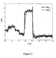
- the figure2 illustrates the estimation ( PMI est ) of the cylinder-to-cylinder torque on an operating point at 1500tr / min, from the estimator according to the invention (5) and a function ⁇ defined by equation (7) .
- the figure 2 also illustrates the average reference torque ( PMI ref ) (calculated from cylinder pressure measurements on the engine test bench). We observe a very good estimate of the signal.
- the adaptive filter thus produced is efficient, and above all does not require any additional adjustment in the case of change of the operating point. No identification phase is necessary, only a measurement and model noise adjustment must be carried out, once and only once
- An engine control can thus, from the reconstructed couples, adapt the fuel masses injected into each of the cylinders so that the pairs are balanced in all the cylinders.
Description
La présente invention concerne une méthode pour estimer en temps réel le régime instantané produit par chacun des cylindres d'un moteur à combustion interne à partir du capteur de régime instantanée située au bout de la transmission.The present invention relates to a method for estimating in real time the instantaneous speed produced by each cylinder of an internal combustion engine from the instantaneous speed sensor located at the end of the transmission.
La connaissance du régime instantanée pour chaque cylindre permet d'estimer le couple moyen produit par chaque cylindre.The knowledge of the instantaneous regime for each cylinder makes it possible to estimate the average torque produced by each cylinder.
L'estimation du couple moyen produit par chaque cylindre est importante pour tous les véhicules, qu'ils soient à motorisation essence ou à motorisation diesel. Dans le premier cas, elle conditionne une bonne combustion du mélange lorsque la richesse est proche de un, et donc sensible à des problèmes de différence cylindre à cylindre. Dans le second cas, l'intérêt de la connaissance du couple permet un rééquilibrage pour obtenir un fonctionnement optimum. En particulier, les catalyseurs utilisant un piège à NOx perdent de leur efficacité avec le temps. Afin de revenir à une efficacité optimale, le couple de chacun des cylindres doit être maintenue identique pendant quelques secondes, pour revenir ensuite en fonctionnement normal à un mélange pauvre. La dépollution par catalyse DeNOx nécessite donc un pilotage précis du couple cylindre par cylindre.Estimating the average torque produced by each cylinder is important for all vehicles, whether they are petrol or diesel engines. In the first case, it conditions a good combustion of the mixture when the richness is close to one, and therefore sensitive to cylinder-to-cylinder difference problems. In the second case, the interest of the knowledge of the couple allows a rebalancing to obtain an optimum operation. In particular, catalysts using a NOx trap lose their effectiveness over time. In order to return to optimum efficiency, the torque of each of the cylinders must be kept identical for a few seconds, then return to normal operation at a lean mixture. The DeNOx catalysis depollution therefore requires precise control of the cylinder-by-cylinder torque.
Pour ce faire, un capteur de régime instantané est placé au bout de la transmission. Cette mesure est très déformée par la transmission et est bruitée.To do this, an instantaneous speed sensor is placed at the end of the transmission. This measurement is very distorted by the transmission and is noisy.
Afin de contrôler d'une manière plus précise, et surtout individuelle, l'injection des masses de carburant dans les cylindres, une reconstruction du couple cylindre à cylindre est indispensable. L'implantation d'un couplomètre numérique sous chaque cylindre est impensable sur véhicule étant donné leur prix de revient.In order to control in a more precise way, and especially individual, the injection of the masses of fuel in the cylinders, a reconstruction of the cylinder to cylinder torque is indispensable. The implementation of a digital couplometer under each cylinder is unthinkable on vehicle given their cost.
La méthode selon l'invention propose de définir un estimateur fonctionnant à partir de la mesure en bout de la chaîne de transmission pour estimer le régime instantané sous chacun des cylindres.The method according to the invention proposes to define an estimator operating from the measurement at the end of the transmission chain to estimate the instantaneous speed under each of the cylinders.
L'invention concerne une méthode pour estimer en temps réel le régime instantané produit par chacun des cylindres d'un moteur à combustion interne comprenant au moins un système de transmission relié aux cylindres et un capteur qui réalise en temps réel une mesure (x1 ) du régime instantané en bout dudit système de transmission.The invention relates to a method for estimating in real time the instantaneous speed produced by each of the cylinders of an internal combustion engine comprising at least one transmission system connected to the cylinders and a sensor which realizes a measurement ( x 1 ) in real time. instantaneous regime at the end of said transmission system.
La méthode comporte les étapes suivantes :
- a) on construit un modèle physique représentant en temps réel la dynamique dudit système de transmission en fonction : de ladite mesure (x1 ), de coefficients d'une décomposition en série de Fourier dudit régime instantané produit par chacun des cylindres, et en fonction d'un amortissement et d'une fréquence propre caractérisant ledit système de transmission ;
- b) on détermine en temps réel les coefficients de ladite décomposition en série de Fourier en couplant ledit modèle avec un estimateur non linéaire de type adaptatif ;
- c) on réalise une estimation en temps réel du régime instantané produit par chacun des cylindres, à partir desdits coefficients de Fourier.
- a) constructing a physical model representing in real time the dynamics of said transmission system as a function of: said measurement ( x 1 ), coefficients of a Fourier series decomposition of said instantaneous regime produced by each of the cylinders, and in function a damping and a natural frequency characterizing said transmission system;
- b) the coefficients of said Fourier series decomposition are determined in real time by coupling said model with an adaptive type nonlinear estimator;
- c) real time estimation of the instantaneous regime produced by each of the rolls, from said Fourier coefficients.
On peut également estimer en temps réel le couple moyen de chacun des cylindres à partir de l'estimation de ces coefficients.We can also estimate in real time the average torque of each of the cylinders from the estimation of these coefficients.
La méthode selon l'invention peut être appliquée à un contrôle moteur pour adapter les masses de carburant injectées dans chacun des cylindres, afin de régler le couple moyen produit par chacun des cylindres.The method according to the invention can be applied to an engine control to adapt the fuel masses injected into each of the cylinders, in order to adjust the average torque produced by each of the cylinders.
D'autres caractéristiques et avantages de la méthode selon l'invention, apparaîtront à la lecture de la description ci-après d'exemples non limitatifs de réalisations, en se référant aux figures annexées et décrites ci-après.Other characteristics and advantages of the method according to the invention will appear on reading the following description of nonlimiting examples of embodiments, with reference to the appended figures and described below.
-
la
figure 1 illustre l'estimation du régime instantané sous les cylindres par la méthode selon l'invention, sur un point de fonctionnement de 1250tr/min moyenne charge.thefigure 1 illustrates the estimation of the instantaneous speed under the cylinders by the method according to the invention, on an operating point of 1250tr / min average load. -
la
figure 2 illustre l'estimation du couple moyen cylindre à cylindre par la méthode selon l'invention, sur un point de fonctionnement de 1500tr/min.thefigure 2 illustrates the estimation of the average cylinder to cylinder torque by the method according to the invention, on an operating point of 1500tr / min.
La méthode selon l'invention permet d'estimer le régime instantané produit par chacun des cylindres d'un moteur à combustion interne comprenant au moins un système de transmission relié aux cylindres. En bout de ce système de transmission, un capteur réalise en temps réel une mesure du régime instantané. Ce signal est noté x1. Un mesure du régime instantané sous les cylindres déformée par l'arbre de transmission est donc réalisée. La première étape de l'invention consiste donc à « inverser » les effets de la transmission pour obtenir l'information pertinente, c'est-à-dire le régime instantané produit par chacun des cylindres. Cette information pertinente est un signal périodique que l'on note x0. The method according to the invention makes it possible to estimate the instantaneous speed produced by each of the cylinders of an internal combustion engine comprising at least one transmission system connected to the cylinders. At the end of this transmission system, a sensor realizes a measurement of the instantaneous speed in real time. This signal is noted x 1 . An instantaneous speed measurement under the cylinders deformed by the transmission shaft is therefore performed. The first step of the invention is therefore to "reverse" the effects of the transmission to obtain the relevant information, that is to say the instantaneous speed produced by each of the cylinders. This relevant information is a periodic signal that we note x 0 .
La méthode comporte principalement les quatre étapes suivantes :
- 1- on établit, dans une échelle angulaire (c'est-à-dire en fonction de l'angle vilebrequin et non du temps), un modèle physique représentant en temps réel la dynamique du système de transmission ;
- 2- on caractérise le régime instantané produit par chacun des cylindres, par des paramètres quasi invariants au cours du temps, tels que les coefficients de sa décomposition de Fourier ;
- 3- on couple le modèle physique avec un estimateur non linéaire de type adaptatif ;
- 4- on réalise une estimation en temps réel du régime instantané produit par chacun des cylindres à partir de l'estimateur non linéaire de type adaptatif.
- 1-we establish, in an angular scale (that is to say according to the crank angle and not time), a physical model representing in real time the dynamics of the transmission system;
- 2- the instantaneous regime produced by each of the cylinders is characterized by quasi-invariant parameters over time, such as the coefficients of its Fourier decomposition;
- 3- we couple the physical model with a nonlinear estimator of adaptive type;
- 4-real time estimation of the instantaneous regime produced by each of the cylinders from the adaptive type nonlinear estimator.
Pour estimer le signal x0 , c'est-à-dire le régime instantané sous les cylindres, on définit dans un premier temps un modèle physique de la dynamique du système de transmission. Pour ce faire, l'on considère que ce système se comporte comme un système du deuxième ordre qui se compose de deux paramètres :
-
ω : la fréquence propre de la transmission dans le référentiel tournant -
ζ : l'amortissement de la transmission
-
ω : the natural frequency of transmission in the rotating repository -
ζ : the damping of the transmission
Ainsi, et en se plaçant dans l'échelle angulaire, la dynamique de l'arbre de transmission s'écrit : 
avec :
x1 : le régime instantané au bout de la chaîne de transmission : la mesure (y)
x0 : le régime instantané sous les cylindres : l'inconnu
α : l'angle vilebrequin du système de transmissionThus, and placing itself in the angular scale, the dynamics of the transmission shaft is written:
with:
x 1 : the instantaneous regime at the end of the transmission chain: the measure ( y )
x 0 : the instantaneous regime under the cylinders: the unknown
α: the crankshaft angle of the transmission system
On peut effectuer un changement de variable en posant : 
Le régime instantané sous les cylindres x0 est périodique donc w 0 aussi. La dynamique peut donc se réécrire sous la forme suivante : 
avec : 


![]()
with: ![]()
Cette équation (2) constitue le modèle physique représentant en temps réel la dynamique du système de transmission. Une estimation du signal w 0 permet de déterminer une estimation du signal x0 à partir de l'équation (1).This equation (2) constitutes the physical model representing in real time the dynamics of the transmission system. An estimate of the signal w 0 makes it possible to determine an estimate of the signal x 0 from equation (1).
On recherche à estimer, à partir de ce modèle physique et de la mesure y (égale à x1 ), le signal x0 , c'est-à-dire le régime instantané produit par chacun des cylindres. Pour réaliser cette estimation en temps réel, la méthode selon l'invention caractérise ce signal x0 par des paramètres quasi invariants au cours du temps. En d'autres termes, on définit le signal x0 à l'aide de paramètres qui, à un instant donné, sont des constantes. Pour ce faire, on exploite le fait que le signal x0 est mécaniquement périodique. Ainsi, au lieu de réaliser une estimation du signal fortement variable x0 , on peut estimer les coefficients de Fourier de ce signal. On peut également utiliser tous paramètres permettant de décrire le signal x0 en relation avec son caractère périodique.We seek to estimate, from this physical model and the measurement y (equal to x 1 ), the signal x 0 , that is to say the instantaneous regime produced by each of the cylinders. To make this estimation in real time, the method according to the invention characterizes this signal x 0 by quasi-invariant parameters over time. In other words, the signal x 0 is defined using parameters which, at a given moment, are constants. To do this, we exploit the fact that the signal x 0 is mechanically periodic. Thus, instead of making an estimate of the highly variable signal x 0 , it is possible to estimate the Fourier coefficients of this signal. It is also possible to use any parameters making it possible to describe the signal x 0 in relation to its periodic character.
La décomposition en coefficients de Fourier du signal x0 , développée en complexe pour la clarté de l'exposé, s'écrit ainsi : 
Les dj représentent les 2n+1 coefficients de Fourier de la décomposition du signal x0 .The Fourier coefficient decomposition of the signal x 0 , developed in complex for the clarity of the exposition, is written as follows:
The dj represent the 2 n + 1 Fourier coefficients of the decomposition of the signal x 0 .
On définit ainsi un signal traduisant le régime instantané x0 , en fonction des paramètres dj , invariants au cours du temps.A signal is thus defined translating the instantaneous regime x 0 , as a function of the parameters d j , invariant over time.
Pour estimer les paramètres dj on peut à nouveau utiliser le changement de variable w0 et utiliser le modèle physique décrit par le système (2). Le signal w0 est également mécaniquement périodique, et sa décomposition en coefficients de Fourier, développée en complexe pour la clarté de l'exposé, s'écrit ainsi : 
Les cj représentent les 2n+1 coefficients de Fourier.To estimate the parameters d, we can again use the change of variable w 0 and use the physical model described by the system (2). The signal w 0 is also mechanically periodic, and its decomposition in Fourier coefficients, developed in complex for the clarity of the exposition, is written as follows:
The c j represent the 2 n + 1 Fourier coefficients.
L'estimation de ces coefficients cj permet ainsi d'estimer la décomposition en coefficients de Fourier du signal x0 et donc également du signal x0 lui-même.The estimation of these coefficients c j thus makes it possible to estimate the Fourier coefficient decomposition of the signal x 0 and thus also of the signal x 0 itself.
En n'utilisant qu'un nombre fini d'harmoniques ([- n;+n]), le modèle physique représentant en temps réel la dynamique du système de transmission s'écrit alors : 
A partir du modèle physique décrit par le système (4), on définit un estimateur non linéaire de type adaptatif comportant d'une part, un terme lié à la dynamique et d'autre part, un terme de correction : 
avec :
x̂ : estimateur de x
ĉj : estimateur de cj
L : une matrice à calibrer
Lj : des matrices à calibrer
Un choix de matrices L et Lj assurant la convergence de l'estimateur est : 
with:
x: x estimator
ĉ j : estimator of c j
L : a matrix to calibrate
L j : matrices to be calibrated
A choice of matrices L and L j ensuring the convergence of the estimator is:
Le système d'équations (5) représente un estimateur non linéaire de type adaptatif permettant d'estimer les coefficients cj de la décomposition en coefficients de Fourier du signal w 0.The system of equations (5) represents an adaptive-type nonlinear estimator for estimating the coefficients c j of the Fourier coefficient decomposition of the signal w 0 .
On a construit cet estimateur (5) à partir du changement de variable w 0, mais il est évident que de la même façon, il est possible de construire un estimateur non linéaire de type adaptatif directement à partir de x0 .This estimator (5) was constructed from the variable change w 0 , but it is obvious that in the same way it is possible to construct an adaptive-type nonlinear estimator directly from x 0 .
On estime ensuite à partir de l'estimation ĉj des coefficients cj le régime instantané produit par chacun des cylindres x0 .It is then estimated from the estimate ĉ j coefficients c j the instantaneous regime produced by each cylinder x 0 .
L'estimateur (5) permet de reconstruire w0 à travers ses coefficients de Fourier cj . L'objectif est de reconstruire x0 . Grâce à l'expression de w0 donnée par l'équation (1), on exprime les coefficients dj en fonction des coefficients cj : 
On obtient donc ainsi l'expression du régime instantané produit par chaque cylindres, à l'aide des équations (3) et (6), et les coefficients de sa décomposition de Fourier par l'équation (6).We thus obtain the expression of the instantaneous regime produced by each cylinder, using equations (3) and (6), and the coefficients of its Fourier decomposition by equation (6).
Selon l'invention, il est possible de fournir une estimation du couple moyen produit par chaque cylindre à partir de l'estimation du régime instantané produit par chaque cylindres (x0 ) et plus précisément à partir de l'estimation de sa décomposition de Fourier en coefficients dj .According to the invention, it is possible to provide an estimate of the average torque produced by each cylinder from the estimate of the instantaneous regime produced by each cylinder ( x 0 ) and more precisely from the estimate of its Fourier decomposition. in coefficients d j .
La connaissance du couple moyen produit par chaque cylindre est une information fondamentale et pertinente pour l'estimation de la combustion ; elle est l'image de la combustion que voit le moteur.The knowledge of the average torque produced by each cylinder is a fundamental and relevant information for the estimation of the combustion; it is the image of the combustion that the engine sees.
L'estimateur précédent (5) nous permet d'estimer le signal du régime sous les cylindres mais aussi sa décomposition de Fourier. Or, plus le couple est important plus l'excitation sur l'arbre est grande. Dans ce sens il est possible de corréler le couple produit par le cylindre et les coefficients de Fourier de la décomposition du signal du régime instantané (x0 ).The previous estimator (5) allows us to estimate the signal of the regime under the cylinders but also its Fourier decomposition. However, the more torque is important the greater the excitement on the tree. In this sense it is possible to correlate the torque produced by the cylinder and the Fourier coefficients of the decomposition of the instantaneous regime signal ( x 0 ).
De façon générale, il est donc possible d'identifier une fonction ϕ, qui permet de déterminer le PMI (Pression Moyenne Indiquée) ou, de façon équivalente, le couple moyen à partir des coefficients dj : 
Cette fonction ϕ peut être une fonction polynomiale. Elle peut être déterminée empiriquement à partir d'essai. Par exemple on peut choisir la fonction suivante : 
avec ϕ0 une constante à calibrer en fonction du régime moteur utilisé à l'aide de corrélations avec les mesures de banc moteur. Ce calibrage peut être réalisé à partir d'une tabulation, issue d'une optimisation linéaire consistant à ajuster la valeur de ϕ0 pour que les estimations soient le plus proche possible des paramètres du moteur (paramètres permettant le calibrage du moteur et fournis par le constructeur).This function φ can be a polynomial function. It can be determined empirically from test. For example we can choose the following function:
with φ 0 a constant to be calibrated according to the engine speed used using correlations with the engine bench measurements. This calibration can be done at from a tabulation, resulting from a linear optimization consisting of adjusting the value of φ 0 so that the estimates are as close as possible to the engine parameters (parameters allowing the calibration of the engine and supplied by the manufacturer).
La
La
Le filtre adaptatif ainsi réalisé est performant, et surtout ne nécessite aucun réglage supplémentaire dans le cas de changement du point de fonctionnement. Aucune phase d'identification n'est nécessaire, seul un réglage des bruits de mesure et de modèle doit être effectué, une seule et unique foisThe adaptive filter thus produced is efficient, and above all does not require any additional adjustment in the case of change of the operating point. No identification phase is necessary, only a measurement and model noise adjustment must be carried out, once and only once
Un contrôle moteur pourra ainsi, à partir des couples reconstruits, adapter les masses de carburant injectées dans chacun des cylindres afin que les couples soient équilibrées dans tous les cylindres.An engine control can thus, from the reconstructed couples, adapt the fuel masses injected into each of the cylinders so that the pairs are balanced in all the cylinders.
Les intérêts d'une estimation du régime instantané produit par chaque cylindre et l'estimation du couple moyen cylindre à cylindre sont nombreux :
- réduction des émissions polluantes ;
- amélioration de l'agrément de conduite (régularisation du couple délivré) ;
- réduction de la consommation de carburant ;
- diagnostic du système d'injection (détection de la dérive d'un injecteur ou de la défaillance du système d'injection).
- reduction of polluting emissions;
- improvement of the driving pleasure (regularization of the delivered torque);
- reduction of fuel consumption;
- diagnosis of the injection system (detection of the drift of an injector or the failure of the injection system).
Claims (3)
- A method for real-time estimation of the instantaneous condition produced by each of the cylinders of an internal combustion engine comprising at least one transmission system connected to the cylinders and a detector which performs in real time a measurement (x1) of the instantaneous condition at the end of said transmission system, characterised in that it comprises the following steps:a) constructing a physical model representing in real time the dynamics of said system transmission in dependence on: the crankshaft angle, said measurement (x1), coefficients of a Fourier series analysis of said instantaneous condition produced by each of the cylinders, and in dependence on damping and a natural frequency characterising said transmission system;b) determining in real time the coefficients of said Fourier series analysis by coupling said model to a non-linear adaptive type estimator; andc) effecting an estimation in real time of the instantaneous condition produced by each of the cylinders from said Fourier coefficients.
- A method according to claim 1 wherein the mean torque of each of the cylinders is estimated in real time from the estimation of said coefficients.
- A method according to the preceding claims for adapting by an engine control the masses of fuel injected into each of the cylinders in order to regulate the mean torque produced by each of the cylinders.
Applications Claiming Priority (2)
| Application Number | Priority Date | Filing Date | Title |
|---|---|---|---|
| FR0509624A FR2891012B1 (en) | 2005-09-20 | 2005-09-20 | METHOD OF ESTIMATING THE INSTANTANEOUS REGIME PRODUCED BY EACH OF THE CYLINDERS OF AN INTERNAL COMBUSTION ENGINE |
| PCT/FR2006/002127 WO2007034057A1 (en) | 2005-09-20 | 2006-09-18 | Method for estimating instantaneous speed produced by each of the cylinders of an internal combustion engine |
Publications (2)
| Publication Number | Publication Date |
|---|---|
| EP1931868A1 EP1931868A1 (en) | 2008-06-18 |
| EP1931868B1 true EP1931868B1 (en) | 2013-04-17 |
Family
ID=36516468
Family Applications (1)
| Application Number | Title | Priority Date | Filing Date |
|---|---|---|---|
| EP06808149.6A Expired - Fee Related EP1931868B1 (en) | 2005-09-20 | 2006-09-18 | Method for estimating instantaneous speed produced by each of the cylinders of an internal combustion engine |
Country Status (5)
| Country | Link |
|---|---|
| US (1) | US8024166B2 (en) |
| EP (1) | EP1931868B1 (en) |
| JP (1) | JP2009509089A (en) |
| FR (1) | FR2891012B1 (en) |
| WO (1) | WO2007034057A1 (en) |
Families Citing this family (7)
| Publication number | Priority date | Publication date | Assignee | Title |
|---|---|---|---|---|
| FR2938093A1 (en) * | 2008-11-04 | 2010-05-07 | Peugeot Citroen Automobiles Sa | Internal combustion engine calibrating method for motor vehicle, involves performing points extrapolation and widened area determination in repeated manner when stop conditions are not satisfied, and selecting final area as experiment area |
| FR2992359A1 (en) * | 2012-06-25 | 2013-12-27 | Renault Sa | Method for detecting fault of combustion diesel engine system of motor car, involves estimating torque value from combustion of amplitude values, and comparing estimated amplitude values with threshold value to detect any engine failures |
| SE537656C2 (en) * | 2013-06-10 | 2015-09-22 | Scania Cv Ab | Procedure for estimating a torque generated by an internal combustion engine |
| JP6544479B2 (en) | 2016-03-18 | 2019-07-17 | 富士通株式会社 | Engine torque estimation device, engine control system and engine torque estimation method |
| JP6930268B2 (en) * | 2017-07-27 | 2021-09-01 | 富士通株式会社 | Calculation device, calculation method, and engine control system |
| JP7431512B2 (en) * | 2019-05-23 | 2024-02-15 | 日立Astemo株式会社 | Internal combustion engine control device |
| CN113818963B (en) * | 2021-09-23 | 2022-10-14 | 宁波吉利罗佑发动机零部件有限公司 | Engine torque prediction method and device and computer storage medium |
Family Cites Families (15)
| Publication number | Priority date | Publication date | Assignee | Title |
|---|---|---|---|---|
| JP3404910B2 (en) * | 1994-09-14 | 2003-05-12 | 日産自動車株式会社 | Shift shock reduction device for continuously variable transmission |
| DE19532136A1 (en) * | 1995-08-31 | 1997-03-06 | Clouth Gummiwerke Ag | Drive system, in particular for a motor vehicle, and method for operating the same |
| US5771482A (en) * | 1995-12-15 | 1998-06-23 | The Ohio State University | Estimation of instantaneous indicated torque in multicylinder engines |
| JPH09195826A (en) * | 1996-01-12 | 1997-07-29 | Yamaha Motor Co Ltd | Air-fuel ratio control method of multicylinder engine |
| FR2752018B1 (en) * | 1996-08-02 | 1998-09-04 | Renault | METHOD FOR DETECTING COMBUSTION RATES OF AN INTERNAL COMBUSTION ENGINE |
| DE19741965C1 (en) * | 1997-09-23 | 1999-01-21 | Siemens Ag | Multi-cylinder fuel injected IC engine running smoothness control method |
| IT1299857B1 (en) * | 1998-02-20 | 2000-04-04 | Magneti Marelli Spa | METHOD FOR DETERMINING THE TREND OF THE INTERNAL PRESSURE IN A CYLINDER OF AN ENDOTHERMIC ENGINE. |
| IT1305390B1 (en) * | 1998-09-10 | 2001-05-04 | Magneti Marelli Spa | METHOD FOR DETERMINING THE PERFORMANCE OF THE TORQUE LOAD IN AN ENDOTHERMAL ENGINE |
| DE10017107A1 (en) * | 2000-04-06 | 2001-10-18 | Bosch Gmbh Robert | Method for compensation of the rotational irregularity in the speed detection |
| US6363318B1 (en) * | 2000-06-21 | 2002-03-26 | Cummins Engine Company, Inc. | Method to compensate errors in engine speed measurement |
| US6866024B2 (en) * | 2001-03-05 | 2005-03-15 | The Ohio State University | Engine control using torque estimation |
| DE10123022B4 (en) * | 2001-05-11 | 2005-06-23 | Siemens Ag | Speed detection method |
| JP2003056438A (en) * | 2001-08-10 | 2003-02-26 | Moric Co Ltd | Vehicular engine control method and system |
| US7261671B2 (en) * | 2003-09-10 | 2007-08-28 | Ford Global Technologies, Llc | Hybrid vehicle powertrain with a multiple-ratio power transmission mechanism |
| DE602004009400T2 (en) * | 2004-01-31 | 2008-07-10 | Ford Global Technologies, LLC, Dearborn | Method for determining speed fluctuations of a motor |
-
2005
- 2005-09-20 FR FR0509624A patent/FR2891012B1/en not_active Expired - Fee Related
-
2006
- 2006-09-18 US US12/067,523 patent/US8024166B2/en not_active Expired - Fee Related
- 2006-09-18 EP EP06808149.6A patent/EP1931868B1/en not_active Expired - Fee Related
- 2006-09-18 JP JP2008531731A patent/JP2009509089A/en active Pending
- 2006-09-18 WO PCT/FR2006/002127 patent/WO2007034057A1/en active Application Filing
Also Published As
| Publication number | Publication date |
|---|---|
| JP2009509089A (en) | 2009-03-05 |
| US8024166B2 (en) | 2011-09-20 |
| WO2007034057A1 (en) | 2007-03-29 |
| US20080319725A1 (en) | 2008-12-25 |
| FR2891012B1 (en) | 2011-02-11 |
| EP1931868A1 (en) | 2008-06-18 |
| FR2891012A1 (en) | 2007-03-23 |
Similar Documents
| Publication | Publication Date | Title |
|---|---|---|
| EP1931868B1 (en) | Method for estimating instantaneous speed produced by each of the cylinders of an internal combustion engine | |
| EP1729001B1 (en) | Estimation method using a non-linear adaptive filter of air-fuel mixture richness in a cylinder of a combustion engine | |
| FR2898411A1 (en) | REAL-TIME ESTIMATION METHOD OF ENGINE COMBUSTION PARAMETERS FROM VIBRATORY SIGNALS | |
| EP3619412B1 (en) | Method for filtering an air-fuel ratio signal produced by an engine exhaust sensor | |
| FR3065990A1 (en) | METHOD FOR REALIZING A DYNAMIC OF ADAPTING A WEALTH VALUE TO A SET IN A MOTOR | |
| EP1729000A1 (en) | Method for estimating the air/fuel ratio in a cylinder of an internal combustion engine using an extended Kalman filter | |
| EP1052488B1 (en) | Procedure and device for measuring the torque of an internal combustion engine | |
| EP2530446B1 (en) | Method for estimating the pinking intensity of an internal combustion engine by inverting a wave equation | |
| FR3044713A1 (en) | METHOD AND DEVICE FOR DETERMINING THE FLOW OF AIR ENTERING THE INTAKE MANIFOLD OF A TWO-STROKE ENGINE | |
| EP1090219B1 (en) | Method for correcting ignition advance of an internal combustion engine | |
| EP1607605B1 (en) | Pressure estimating system in the exhaust manifold of a diesel engine and method for calibrating said system | |
| FR2984414A1 (en) | Method for calibration of internal combustion engine of vehicle, involves building quantification model, and calculating set of quantities of emitted pollutants from interpolation laws that are provided as function of temperatures | |
| FR2919678A1 (en) | METHOD AND DEVICE FOR DIAGNOSING INJECTOR LEAKAGE IN AN INTERNAL COMBUSTION ENGINE | |
| FR2835281A1 (en) | Method for estimating mass of air admitted into engine combustion chamber consists of modeling air mass as function of pressure variation in combustion chamber from polytropic gas compression law | |
| FR2949511A1 (en) | Knock intensity estimating method for internal combustion engine, involves determining coefficients of Fourier decomposition of signal in real-time, and deducing parameter correlated with knock intensity from coefficients in real-time | |
| FR2923266A1 (en) | ESTIMATING THE EFFECTS OF THE EVAPORATION OF DILUTED FUEL IN THE OIL OF AN INTERNAL COMBUSTION ENGINE | |
| WO2004074662A1 (en) | Procede de detection de rates de combustion par filtrage | |
| FR3100844A1 (en) | Method for determining the mass of gas enclosed in a combustion chamber | |
| FR3064679A1 (en) | METHOD FOR DETECTING PRE-IGNITION OF FRESH AIR AND FUEL MIXTURE | |
| FR2934642A1 (en) | Injector's dead time correction method for e.g. direct or indirect fuel injection type petrol engine, of motor vehicle, involves padding cartography of dead time or corrected minimum activation time based on fuel pressure of ramp | |
| FR2917459A3 (en) | Drift and dispersion correcting method for vehicle, involves comparing two air flows, and calculating correction to be subjected to first air flow that is measured by using air flow measuring device | |
| FR3116564A1 (en) | Method for determining the mass of sucked gas by means of the frequency of the pressure oscillations | |
| FR3075269A1 (en) | METHOD FOR DETECTING PRE-IGNITION OF FRESH AIR AND FUEL MIXTURE | |
| EP2212537B1 (en) | Method of testing engines based on graphic signatures | |
| WO2007074271A1 (en) | Engine control method for improving an engine combustion diagnosis |
Legal Events
| Date | Code | Title | Description |
|---|---|---|---|
| PUAI | Public reference made under article 153(3) epc to a published international application that has entered the european phase |
Free format text: ORIGINAL CODE: 0009012 |
|
| 17P | Request for examination filed |
Effective date: 20080421 |
|
| AK | Designated contracting states |
Kind code of ref document: A1 Designated state(s): DE GB IT |
|
| RBV | Designated contracting states (corrected) |
Designated state(s): DE GB IT |
|
| 17Q | First examination report despatched |
Effective date: 20100607 |
|
| DAX | Request for extension of the european patent (deleted) | ||
| REG | Reference to a national code |
Ref country code: DE Ref legal event code: R079 Ref document number: 602006035752 Country of ref document: DE Free format text: PREVIOUS MAIN CLASS: F02D0041140000 Ipc: F02D0041000000 |
|
| RIC1 | Information provided on ipc code assigned before grant |
Ipc: F02D 41/00 20060101AFI20121109BHEP Ipc: F02D 41/14 20060101ALI20121109BHEP Ipc: F02D 41/34 20060101ALI20121109BHEP |
|
| GRAP | Despatch of communication of intention to grant a patent |
Free format text: ORIGINAL CODE: EPIDOSNIGR1 |
|
| GRAS | Grant fee paid |
Free format text: ORIGINAL CODE: EPIDOSNIGR3 |
|
| GRAA | (expected) grant |
Free format text: ORIGINAL CODE: 0009210 |
|
| AK | Designated contracting states |
Kind code of ref document: B1 Designated state(s): DE GB IT |
|
| REG | Reference to a national code |
Ref country code: GB Ref legal event code: FG4D Free format text: NOT ENGLISH |
|
| RIN1 | Information on inventor provided before grant (corrected) |
Inventor name: CHAUVIN, JONATHAN Inventor name: CORDE, GILLES Inventor name: ROUCHON, PIERRE Inventor name: PETIT, NICOLAS |
|
| REG | Reference to a national code |
Ref country code: DE Ref legal event code: R096 Ref document number: 602006035752 Country of ref document: DE Effective date: 20130606 |
|
| PGFP | Annual fee paid to national office [announced via postgrant information from national office to epo] |
Ref country code: IT Payment date: 20130921 Year of fee payment: 8 |
|
| PGFP | Annual fee paid to national office [announced via postgrant information from national office to epo] |
Ref country code: DE Payment date: 20130930 Year of fee payment: 8 |
|
| PLBE | No opposition filed within time limit |
Free format text: ORIGINAL CODE: 0009261 |
|
| STAA | Information on the status of an ep patent application or granted ep patent |
Free format text: STATUS: NO OPPOSITION FILED WITHIN TIME LIMIT |
|
| 26N | No opposition filed |
Effective date: 20140120 |
|
| REG | Reference to a national code |
Ref country code: DE Ref legal event code: R097 Ref document number: 602006035752 Country of ref document: DE Effective date: 20140120 |
|
| GBPC | Gb: european patent ceased through non-payment of renewal fee |
Effective date: 20130918 |
|
| PG25 | Lapsed in a contracting state [announced via postgrant information from national office to epo] |
Ref country code: GB Free format text: LAPSE BECAUSE OF NON-PAYMENT OF DUE FEES Effective date: 20130918 |
|
| REG | Reference to a national code |
Ref country code: DE Ref legal event code: R119 Ref document number: 602006035752 Country of ref document: DE |
|
| REG | Reference to a national code |
Ref country code: DE Ref legal event code: R119 Ref document number: 602006035752 Country of ref document: DE Effective date: 20150401 |
|
| PG25 | Lapsed in a contracting state [announced via postgrant information from national office to epo] |
Ref country code: DE Free format text: LAPSE BECAUSE OF NON-PAYMENT OF DUE FEES Effective date: 20150401 |
|
| PG25 | Lapsed in a contracting state [announced via postgrant information from national office to epo] |
Ref country code: IT Free format text: LAPSE BECAUSE OF NON-PAYMENT OF DUE FEES Effective date: 20140918 |