EP1931009A2 - Methods for synchronising a plurality of generators - Google Patents
Methods for synchronising a plurality of generators Download PDFInfo
- Publication number
- EP1931009A2 EP1931009A2 EP20070023435 EP07023435A EP1931009A2 EP 1931009 A2 EP1931009 A2 EP 1931009A2 EP 20070023435 EP20070023435 EP 20070023435 EP 07023435 A EP07023435 A EP 07023435A EP 1931009 A2 EP1931009 A2 EP 1931009A2
- Authority
- EP
- European Patent Office
- Prior art keywords
- supply network
- generators
- synchronisation signal
- fault condition
- frequency
- Prior art date
- Legal status (The legal status is an assumption and is not a legal conclusion. Google has not performed a legal analysis and makes no representation as to the accuracy of the status listed.)
- Withdrawn
Links
- 238000000034 method Methods 0.000 title claims abstract description 23
- 230000001360 synchronised effect Effects 0.000 claims description 9
- 230000003247 decreasing effect Effects 0.000 claims description 3
- 238000010586 diagram Methods 0.000 description 4
- 230000006698 induction Effects 0.000 description 3
- 230000006870 function Effects 0.000 description 2
- 238000011084 recovery Methods 0.000 description 2
- 230000000717 retained effect Effects 0.000 description 2
- 230000001052 transient effect Effects 0.000 description 2
- 230000005540 biological transmission Effects 0.000 description 1
- 238000004891 communication Methods 0.000 description 1
- 238000010276 construction Methods 0.000 description 1
- 230000007423 decrease Effects 0.000 description 1
- 230000001934 delay Effects 0.000 description 1
- 230000004907 flux Effects 0.000 description 1
- 230000003287 optical effect Effects 0.000 description 1
- 239000013307 optical fiber Substances 0.000 description 1
- 238000005070 sampling Methods 0.000 description 1
Images


Classifications
-
- F—MECHANICAL ENGINEERING; LIGHTING; HEATING; WEAPONS; BLASTING
- F03—MACHINES OR ENGINES FOR LIQUIDS; WIND, SPRING, OR WEIGHT MOTORS; PRODUCING MECHANICAL POWER OR A REACTIVE PROPULSIVE THRUST, NOT OTHERWISE PROVIDED FOR
- F03D—WIND MOTORS
- F03D9/00—Adaptations of wind motors for special use; Combinations of wind motors with apparatus driven thereby; Wind motors specially adapted for installation in particular locations
- F03D9/20—Wind motors characterised by the driven apparatus
- F03D9/25—Wind motors characterised by the driven apparatus the apparatus being an electrical generator
- F03D9/255—Wind motors characterised by the driven apparatus the apparatus being an electrical generator connected to electrical distribution networks; Arrangements therefor
- F03D9/257—Wind motors characterised by the driven apparatus the apparatus being an electrical generator connected to electrical distribution networks; Arrangements therefor the wind motor being part of a wind farm
-
- H—ELECTRICITY
- H02—GENERATION; CONVERSION OR DISTRIBUTION OF ELECTRIC POWER
- H02J—CIRCUIT ARRANGEMENTS OR SYSTEMS FOR SUPPLYING OR DISTRIBUTING ELECTRIC POWER; SYSTEMS FOR STORING ELECTRIC ENERGY
- H02J3/00—Circuit arrangements for ac mains or ac distribution networks
- H02J3/38—Arrangements for parallely feeding a single network by two or more generators, converters or transformers
-
- F—MECHANICAL ENGINEERING; LIGHTING; HEATING; WEAPONS; BLASTING
- F03—MACHINES OR ENGINES FOR LIQUIDS; WIND, SPRING, OR WEIGHT MOTORS; PRODUCING MECHANICAL POWER OR A REACTIVE PROPULSIVE THRUST, NOT OTHERWISE PROVIDED FOR
- F03D—WIND MOTORS
- F03D7/00—Controlling wind motors
- F03D7/02—Controlling wind motors the wind motors having rotation axis substantially parallel to the air flow entering the rotor
- F03D7/028—Controlling wind motors the wind motors having rotation axis substantially parallel to the air flow entering the rotor controlling wind motor output power
- F03D7/0284—Controlling wind motors the wind motors having rotation axis substantially parallel to the air flow entering the rotor controlling wind motor output power in relation to the state of the electric grid
-
- F—MECHANICAL ENGINEERING; LIGHTING; HEATING; WEAPONS; BLASTING
- F03—MACHINES OR ENGINES FOR LIQUIDS; WIND, SPRING, OR WEIGHT MOTORS; PRODUCING MECHANICAL POWER OR A REACTIVE PROPULSIVE THRUST, NOT OTHERWISE PROVIDED FOR
- F03D—WIND MOTORS
- F03D7/00—Controlling wind motors
- F03D7/02—Controlling wind motors the wind motors having rotation axis substantially parallel to the air flow entering the rotor
- F03D7/04—Automatic control; Regulation
- F03D7/042—Automatic control; Regulation by means of an electrical or electronic controller
- F03D7/048—Automatic control; Regulation by means of an electrical or electronic controller controlling wind farms
-
- H—ELECTRICITY
- H02—GENERATION; CONVERSION OR DISTRIBUTION OF ELECTRIC POWER
- H02J—CIRCUIT ARRANGEMENTS OR SYSTEMS FOR SUPPLYING OR DISTRIBUTING ELECTRIC POWER; SYSTEMS FOR STORING ELECTRIC ENERGY
- H02J3/00—Circuit arrangements for ac mains or ac distribution networks
- H02J3/38—Arrangements for parallely feeding a single network by two or more generators, converters or transformers
- H02J3/40—Synchronising a generator for connection to a network or to another generator
-
- Y—GENERAL TAGGING OF NEW TECHNOLOGICAL DEVELOPMENTS; GENERAL TAGGING OF CROSS-SECTIONAL TECHNOLOGIES SPANNING OVER SEVERAL SECTIONS OF THE IPC; TECHNICAL SUBJECTS COVERED BY FORMER USPC CROSS-REFERENCE ART COLLECTIONS [XRACs] AND DIGESTS
- Y02—TECHNOLOGIES OR APPLICATIONS FOR MITIGATION OR ADAPTATION AGAINST CLIMATE CHANGE
- Y02E—REDUCTION OF GREENHOUSE GAS [GHG] EMISSIONS, RELATED TO ENERGY GENERATION, TRANSMISSION OR DISTRIBUTION
- Y02E10/00—Energy generation through renewable energy sources
- Y02E10/70—Wind energy
- Y02E10/72—Wind turbines with rotation axis in wind direction
-
- Y—GENERAL TAGGING OF NEW TECHNOLOGICAL DEVELOPMENTS; GENERAL TAGGING OF CROSS-SECTIONAL TECHNOLOGIES SPANNING OVER SEVERAL SECTIONS OF THE IPC; TECHNICAL SUBJECTS COVERED BY FORMER USPC CROSS-REFERENCE ART COLLECTIONS [XRACs] AND DIGESTS
- Y02—TECHNOLOGIES OR APPLICATIONS FOR MITIGATION OR ADAPTATION AGAINST CLIMATE CHANGE
- Y02E—REDUCTION OF GREENHOUSE GAS [GHG] EMISSIONS, RELATED TO ENERGY GENERATION, TRANSMISSION OR DISTRIBUTION
- Y02E10/00—Energy generation through renewable energy sources
- Y02E10/70—Wind energy
- Y02E10/76—Power conversion electric or electronic aspects
Landscapes
- Engineering & Computer Science (AREA)
- Life Sciences & Earth Sciences (AREA)
- Sustainable Development (AREA)
- Sustainable Energy (AREA)
- Chemical & Material Sciences (AREA)
- Combustion & Propulsion (AREA)
- Mechanical Engineering (AREA)
- General Engineering & Computer Science (AREA)
- Power Engineering (AREA)
- Control Of Eletrric Generators (AREA)
- Supply And Distribution Of Alternating Current (AREA)
- Synchronisation In Digital Transmission Systems (AREA)
Abstract
Description
- The present invention relates to methods for synchronising a plurality of generators connected to a common power grid or supply network during normal operating conditions and also in the event of a network fault. The methods are particularly suitable for use with, but not restricted to, generators that are driven by wind turbines.
- The present invention is particular suitable for synchronising generators using fully rated power converters directly connected to the stator of cage induction electrical machines, permanent magnet electrical machines or superconducting electrical machines.
- It is possible to convert wind energy to electrical energy by using a wind turbine to drive the rotor of an electrical machine, either directly or by means of a gearbox. The ac frequency that is developed at the stator terminals of the electrical machine (the "stator voltage") is directly proportional to the speed of rotation of the rotor for cage induction electrical machines and permanent magnet electrical machines. The voltage at the terminals of the electrical machine also varies as a function of speed and, for cage induction electrical machines, on the flux level.
- For optimum energy capture, the speed of rotation of the output shaft of the wind turbine will vary according to the speed of the wind driving the turbine blades. To limit the energy capture at high wind speeds, the speed of rotation of the output shaft is controlled by altering the pitch of the turbine blades. Matching of the variable voltage and frequency of the electrical machine to the nominally constant voltage and frequency of the supply network can be achieved by using a power converter connected between the stator of the electrical machine and the supply network.
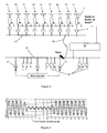
- A schematic diagram of a group of wind turbines is shown in
Figure 1 . Each wind turbine 1a to 1i includes blades and agenerator 2 that incorporates a rotating electrical machine, a power converter and associated control circuits as a combined unit. The output of eachgenerator 2 is supplied through atransformer 4 to a localparallel connection 6a to 6d that in turn is connected by means of anelectrical cable 8 to the supply network orpower grid 10. The conventional arrangement shown inFigure 1 is to have a small number of wind turbines connected to a local parallel connection. For example, the generators ofwind turbines 1a and 1b are connected in parallel to a first localparallel connection 6a, the generators ofwind turbines parallel connection 6b, the generators ofwind turbines 1e and 1f are connected in parallel to a third localparallel connection 6c and the generators ofwind turbines parallel connection 6d. - A number of conventional rotating electrical machines 12 (also called alternators) that are normally sited within a power station, for example, also supply power to the
supply network 10. A number ofloads 14 are also shown connected to thesupply network 10 to represent the users of the power that is distributed through the supply network. - Network codes are used to define the amount of fundamental power and reactive power that electrical machines should export to the
supply network 10 during normal operating conditions and also in the event of a network fault or transient conditions. For a large group of wind turbine generators having a combined output of more than 50 MW, for example, then the network codes may require that the group acts as a conventional rotatingelectrical machine 12 during a network fault. A smaller group of wind turbine generators having a combined output of less than 50 MW, for example, may be subject to less strict requirements. - The
generators 2 of the wind turbines 1a to 1 are fully defined in technical publications and a common feature is an individual synchronisation signal Sin using the prevailing ac voltage at the local parallel connection to the control unit of the power converter to control the phasing of the fundamental power and reactive power that is delivered to the local supply network at any particular time. However, the use of individual synchronisation signals can give rise to stability problems if the fundamental power and reactive power delivered by eachgenerator 2 happens to be different. Further problems with stability can arise if the group of wind turbines is connected to the supply network through one or more very long electrical cables. This might be the case for groups where the wind turbines are sited in remote places such as offshore. - One of the most demanding operations for any generator is when the supply network develops a fault. This is not such of a problem for conventional rotating
electrical machines 12 because they are normally large electrical machines and will continue to rotate, due to their large rotational inertia, so that their internal voltages will continue to produce ac currents at the same frequency as before the fault even if the ac voltage of the supply network falls to a value outside the normal operating range including zero voltages. (In practice, there is likely to be a gradual reduction in the frequency of the ac currents as the conventional rotatingelectrical machine 12 slows down during the lifetime of the fault condition.) It might therefore be said that the conventional rotatingelectrical machine 12 incorporates a "frequency versus time memory" as a result of their physical construction. - As described above, the generators of the wind turbines require the use of the individual synchronisation signals Sin to control the phasing of the fundamental power and reactive power that is delivered to the local supply network. Serious problems can therefore arise during a fault condition when the ac voltage of the local supply network, and hence the prevailing ac voltage at the local parallel connection, falls to a value outside the normal operating range including zero voltages. This might be acceptable for a small group of wind turbines, but if the group of wind turbines is required to act as a conventional rotating
electrical machine 12 then the individual generators must stay synchronised before the start of the network fault, during the network fault, as the network fault is clearing and for the following period of normal operation. For all of these periods, the individual generators of the wind turbine group must export, or be ready to export, the required fundamental power and reactive power to the supply network as defined in the various standards and network codes. This is simply not achievable using individual synchronisation signals Sin that use the prevailing ac voltage at the local parallel connection. -
Figure 3 is a graph of voltage versus time for thesupply network 10 over a series of 20 supply network cycles. Thesupply network 10 is configured for 50 Hz operation but it will be appreciated that the following description is also applicable to a supply network configured to operate at other frequencies such as 60 Hz, for example. Insupply network cycle 4 there is the onset of a supply network fault condition and this lasts until normal operation is established again insupply network cycle 12. The fault condition therefore lasts for 8 supply network cycles, but in practice this may depend on other factors such as the type of fault or transient and the protection apparatus (not shown) associated with thesupply network 10. The retained voltage of thesupply network 10 during the fault condition is 20%, but it will be readily appreciated that the retained voltage can be any level outside the normal operating range including 0%, depending on the fault. -
Figure 4 is a graph of frequency versus time for the ac current produced by a conventional rotatingelectrical machine 12 that is connected to thesupply network 10.Figure 5 is a graph of internal electro-motive force (emf) verses time for the conventional rotatingelectrical machine 12. It can be seen that the internal emf and the frequency of the ac current remain unchanged during the fault condition because the conventional rotatingelectrical machine 12 incorporates a "frequency versus time memory" as mentioned above. -
Figure 6 is a graph of power (fundamental power and reactive power) versus time for anindividual generator 2 of the wind turbine group. It is clear fromFigure 6 that thegenerator 2 loses power completely during the fault condition and takes time to start to output power again once the fault condition has been cleared atsupply network cycle 12. - There is therefore a need for an improved method of synchronising the generators of the individual wind turbines in a wind turbine group to make sure that the fundamental power and reactive power exported by each generator are synchronised for all conditions defined by the network codes.
- The same problems apply to generators that include linear electrical machines driven by wave, tidal and ocean current systems.
- In its broadest sense, the present invention aims to reproduce the "frequency versus time memory" of a conventional rotating electrical machine to enable a plurality of generators to remain synchronised and connected to the supply network or power grid even when the ac voltage of the supply network falls to a value outside the normal operating range during a fault condition. The present invention is therefore particularly applicable to generators that include rotating or linear electrical machines driven by wind, wave, tidal and ocean current systems, for example, and which normally receive individual synchronisation signals.
- The present invention provides a method of synchronising a plurality of generators connected together in parallel to a supply network, the method comprising the steps of generating a common synchronisation signal having a frequency versus time pattern that is the same as the frequency versus time pattern of the supply network during normal operating conditions, and supplying the common synchronisation signal to each of the generators to control the level of power (typically both fundamental power and reactive power) that is supplied to the supply network by the generators.
- Even during normal operating conditions of the supply network, the use of a common synchronisation signal improves the stability of the generators and the export of power to the supply network. However, the use of a common synchronisation signal is of particular benefit during a fault condition of the supply network when the ac voltage of the supply network falls to a value outside the normal operating range until the fault is cleared. This would include the situation where the ac voltage of the supply network falls to zero.
- The common synchronisation signal can be supplied to each of the generators during normal operating conditions of the supply network both before and after a fault condition occurs.
- In some circumstances it can be advantageous to supply the common synchronisation to each of the generators during normal operating conditions of the supply network only before a fault condition occurs, with a different common synchronisation signal being supplied to each of the generators after the fault has been cleared. The common synchronisation signal that is supplied to each of the generators after the fault has been cleared may have a frequency versus time pattern with an increasing frequency. This means that it possible in the period immediately following the fault being cleared to allow for a gradual increase in the frequency of the ac current as a conventional rotating electrical machine recovers and speeds up.
- The method preferably includes the step of supplying a common synchronisation signal to each of the generators both during a fault condition of the supply network. The common synchronisation signal that is supplied during the fault condition may be the same as the common synchronisation signal that is supplied during a normal operating condition of the supply network. Alternatively, a series of common synchronisation signals, each having the same or a different frequency versus time pattern, may be supplied in sequence to the generators during each operating condition of the supply network, i.e. before a fault condition occurs, during the fault condition and after the fault has been cleared.
- The common synchronisation signal that is supplied to each of the generators during a fault condition of the supply network may have a frequency versus time pattern that is the same as the frequency versus time pattern of the supply network that existed during the previous normal operating conditions. This ensures that the generators remain synchronised with each other, and as far as is practicable to any conventional rotating electrical machines on the supply network, so that power can be exported to the supply network at the optimum level both during the fault condition and as soon as the fault is cleared.
- To achieve this the common synchronisation signal that is generated during normal operating conditions of the supply network can be stored and then supplied to each of the generators during a fault condition of the supply network.
- It can sometimes be useful to more closely reproduce the "frequency versus time memory" of a conventional rotating electrical machine by supplying a common synchronisation signal during a fault condition that has a frequency versus time pattern with a decreasing frequency. This allows for the gradual reduction in the frequency of the ac current as the conventional rotating electrical machine slows down during the fault condition.
- The actual rate at which the frequency decreases and increases back to a normal operating frequency (i.e. rapid or gradual recovery), can be selected depending on the particular requirements of the network codes and the operating parameters of the supply network or power grid, for example.
- The common synchronisation signal may be supplied to the generators by any suitable means. For example, the common synchronisation signal may be a wireless signal (such as a radio frequency (RF) signal, for example) transmitted from a controller through a suitable wireless transmitter arrangement. The common synchronisation signal may also be an electrical or optical signal transmitted from a controller through a cable or optical fibre. The common synchronisation signal may also be generated by a controller associated with one of the generators and then transmitted to all of the remaining generators in the wind turbine group. It may be necessary to compensate for hardware delays caused primarily by the transmission time of the common synchronisation signal to the generators.
- In some circumstances the individual generators could select to use an individual synchronisation signal in preference to the common synchronisation signal. This could occur, for example, if the common synchronisation signal has some type of fault and this would then enable the generators to continue to function.
- The present invention further provides an arrangement comprising a plurality of generators connected together in parallel to a supply network, and a controller adapted to generate a common synchronisation signal having a frequency versus time pattern that is the same as the frequency versus time pattern of the supply network during normal operating conditions, and supply the common synchronisation signal to each of the generators to control the level of power that is supplied to the supply network by the generators.
- The generators are preferably connected in parallel to a local parallel connection. The local parallel connection is preferably connected to the supply network by at least one electrical cable.
- The controller can be implemented in a number of different ways. For example, the controller could be implemented in hardware by using a motor to drive a conventional rotating electrical machine at a constant speed in such a way as to produce an ac voltage that would be compatible with the power requirements of the supply network. The ac voltage can then be used to derive a common synchronisation signal that is indicative of the ac voltages of the supply network during normal operating conditions. In the event of a fault on the supply network, the motor could continue to drive the rotating electrical machine at the constant speed or it could be switched off to allow the frequency of the ac current to reduce as the rotating electrical machine slows down. However, it is more likely that the controller will be implemented electronically.
- The controller will normally be powered directly from the supply network but must include an auxiliary power source such as a battery so that it can continue functioning during a fault condition where the ac voltage falls outside the normal operating range.
- The decision about when to supply a derived versus a stored common synchronisation signal to each of the generators will normally be made with reference to the prevailing voltage conditions of the supply network, but it can also be made using external inputs from the operator of the supply network, for example.
- Each generator may include a power converter and associated control circuits. In this case, the controller is preferably adapted to apply the common synchronisation signal to the control circuit of each of the power converters to control the level of power that is output to the supply network by the generators.
- The present invention also provides a plurality of wind turbines, each wind turbine comprising a generator having a stator and a rotor, a power converter, and a turbine assembly including at least one blade for rotating the rotor of the generator, wherein the generators are connected together in parallel to a supply network and are synchronised according to the method described above.
-
-
Figure 1 is a schematic diagram showing a known arrangement of a group of wind turbines, conventional rotating electrical machines and loads connected to a supply network; -
Figure 2 is a schematic diagram showing an arrangement of a group of wind turbines, conventional rotating electrical machines and loads connected to a supply network where the generators of the wind turbines are controlled and synchronised according to a method of the present invention; -
Figure 3 is a graph of voltage versus time for a supply network over a series of 20 supply network cycles; -
Figure 4 is a graph of frequency versus time for the ac current produced by a conventional rotating electrical machine that is connected to the supply network for a situation where the conventional rotating electrical machine does not slow down during a supply network fault condition; -
Figure 5 is a graph of internal electro-motive force (emf) verses time for a conventional rotating electrical machine for a situation where the conventional rotating electrical machine does not slow down during a supply network fault condition; -
Figure 6 is a graph of power versus time for an individual generator of a wind turbine group connected to the supply network that is controlled using individual synchronisation signals that use the prevailing ac voltage at the local parallel connection; -
Figure 7 is a graph of power versus time for an individual generator of a wind turbine group connected to the supply network that is controlled in accordance with the present invention by a common synchronisation signal for a situation where the conventional rotating electrical machine does not slow down during a supply network fault condition; -
Figure 8 is a graph of frequency versus time for the ac current produced by a conventional rotating electrical machine that is connected to the supply network for a situation where the conventional rotating electrical machine gradually slows down during a supply network fault condition before recovering rapidly once the fault condition is cleared; -
Figure 9 is a graph of internal emf verses time for a conventional rotating electrical machine for a situation where the conventional rotating electrical machine gradually slows down during a supply network fault condition before recovering rapidly once the fault condition is cleared; -
Figure 10 is a graph of power versus time for an individual generator of a wind turbine group connected to the supply network that is controlled in accordance with the present invention by a common synchronisation signal for a situation where the conventional rotating electrical machine gradually slows down during a supply network fault condition before recovering rapidly once the fault condition is cleared; -
Figure 11 is a graph of frequency versus time for the ac current produced by a conventional rotating electrical machine that is connected to the supply network for a situation where the conventional rotating electrical machine gradually slows down during a supply network fault condition before recovering gradually once the fault condition is cleared; -
Figure 12 is a graph of internal emf verses time for a conventional rotating electrical machine for a situation where the conventional rotating electrical machine gradually slows down during a supply network fault condition before recovering gradually once the fault condition is cleared; and -
Figure 13 is a graph of power versus time for an individual generator of a wind turbine group connected to the supply network that is controlled in accordance with the present invention by a common synchronisation signal for a situation where the conventional rotating electrical machine gradually slows down during a supply network fault condition before recovering gradually once the fault condition is cleared. - A schematic diagram of a group of wind turbines that are synchronised according to a method of the present invention is shown in
Figure 2 . Although this description focuses on wind turbine applications, it will be obvious to the skilled person that the invention has wider applicability. The arrangement ofFigure 2 is similar in many respects to the arrangement ofFigure 1 and like parts have been given the same reference numerals. - Each wind turbine 1a to 1i includes blades and a
generator 2 that incorporates a power converter and control circuits. The output of eachgenerator 2 is supplied through atransformer 4 to a localparallel connection 16 that in turn is connected by means of a single longelectrical cable 18 to the supply network orpower grid 10. For the purposes of this description it will be assumed that the power output of the group of wind turbines is sufficiently large for the network codes of thesupply network 10 to require that the group act as a conventional rotatingelectrical machine 12 during a network fault. - An
electronic controller 20 derives a common synchronisation signal Scom that is transmitted to each of the generators 2 (or more particularly to each of the control circuits of the power converters) through a series of electrical cables. Thegenerators 2 use the synchronisation signal Scom to control the phasing of the fundamental power and reactive power that is delivered to thesupply network 10 at any particular time. - The
electronic controller 20 has an input signal indicative of the prevailing voltage of thesupply network 10. Thecontroller 20 is therefore able to recognise immediately if thesupply network 10 experiences a fault where the ac voltages fall to a value outside the normal operating range. - The synchronisation signal Scom will normally be directly connected to the same connection point that is used by the individual synchronisation signal Sin. In this case, the synchronisation signal Scom will naturally be a voltage signal of sinusoidal shape with the appropriate voltage level that depends on the design of the particular generators. The waveforms for the synchronisation signal Scom will then be directly as shown in
Figures 7 ,10 and13 . However, the relevant voltage, frequency and phase data can be transmitted to eachgenerator 2 by any type of analogue or digital communication signal and protocol. - When the
supply network 10 is operating normally, the frequency and phase of the synchronisation signal Scom that is derived by theelectronic controller 20 is identical to the prevailing frequency and phase of the ac voltages of thesupply network 10. The synchronisation signal Scom is transmitted to each of thegenerators 2 and is continuously stored in theelectronic controller 20. The regular sampling and storage of the synchronisation signal Scom can be implemented using any suitable electronic storage techniques. - If the
supply network 10 develops a fault condition then theelectronic controller 20 will immediately start to transmit the stored synchronisation signal Scom' to each of thegenerators 2. The phase and frequency of the stored synchronisation signal Scom' that is transmitted during a supply network fault condition is therefore identical to the prevailing frequency and phase of the ac voltages of thesupply network 10 during normal operating conditions (i.e. before the fault condition occurred). This means that the phase of the stored synchronisation signal Scom' transmitted by theelectronic controller 20 during a supply network fault condition may not match the phase of the input signal indicative of the prevailing voltage of thesupply network 10. - Once the
electronic controller 20 recognises that the fault condition has been cleared, it will immediately derive a new synchronisation signal Scom" with a frequency and phase that is identical to the prevailing frequency and phase of the ac voltages supply network. The frequency and phase of the stored synchronisation signal Scom' will then be smoothly changed to become the new synchronisation signal Scom" in a preset period, typically one supply network cycle. -
Figure 7 is a graph of power (fundamental power and reactive power) versus time for anindividual generator 2 of the wind turbine group. Duringsupply network cycles 1 to 4 theelectronic controller 20 transmits a synchronisation signal Scom to thegenerator 2 and stores the synchronisation signal. The frequency and phase of the synchronisation signal Scom that is transmitted to thegenerator 2 duringsupply network cycles 1 to 4 is identical to the prevailing frequency and phase of the ac voltages of the supply network shown inFigure 3 . Atsupply network cycle 4 theelectronic controller 20 recognises that a supply network fault condition has occurred and immediately starts to transmit the stored synchronisation signal Scom' to thegenerator 2. (For the purposes of this example it may be assumed that the synchronisation signal Scom is sampled and stored once every supply network cycle, in which case the stored synchronisation signal Scom' would be the synchronisation signal that was stored duringsupply network cycle 3 before the fault condition occurred.) The stored synchronisation signal Scom' is transmitted duringsupply network cycles 4 to 11. Atsupply network cycle 12 theelectronic controller 20 recognises that the fault has cleared and smoothly changes to transmit a new synchronisation signal Scom" in a preset period. The new synchronisation signal Scom" has a frequency and phase that is identical to the prevailing frequency and phase of the ac voltages of the supply network (i.e. the frequency and phase of the ac voltages of the supply network after the fault is cleared).Figure 7 shows that thegenerator 2 can continue to output power before, during and after a supply network fault condition in exactly the same way as the conventional rotatingelectrical machine 12. - In practice, it might be expected that the frequency of the ac current produced by the conventional rotating
electrical machine 12 would gradually reduce during the fault condition as the conventional rotating electrical machine slows down before recovering rapidly once the fault is cleared. This is shown inFigure 8 , which is a graph of frequency versus time for the ac current produced by the conventional rotatingelectrical machine 12. The frequency reduces gradually in a substantially linear manner throughout the lifetime of the fault condition from a normal operating frequency of 50 Hz insupply network cycle 4 to a frequency of 40 Hz insupply network cycle 12. When the fault is cleared, the frequency of the ac current is restored rapidly to the normal operating frequency of 50 Hz. This can happen if the conventional rotatingelectrical machine 12 is small and is reconnected to other larger electrical machines after the fault, for example. The rate at which the frequency of the ac current will fall will depend on the properties and characteristics of the conventional rotatingelectrical machine 12. -
Figure 9 is a graph of internal emf versus time for the situation where the conventional rotatingelectrical machine 12 slows down. It can be seen that the frequency of the internal emf of the conventional rotatingelectrical machine 12 reduces gradually during the lifetime of the fault condition by noting how the spacing between the adjacent peaks and troughs gradually increases betweensupply network cycles - It is possible to reproduce the gradual reduction in the frequency of the ac current produced by the conventional rotating
electrical machine 12 by reducing the frequency of the synchronisation signal that is transmitted to thegenerators 2 during a supply network fault condition in a corresponding manner. For example, theelectronic controller 20 may transmit a modified synchronisation signal (that is optionally initially based on the frequency and phase of the stored synchronisation signal Scom') where the frequency of the modified synchronisation signal is reduced at a predetermined rate. In this case, a minimum frequency limit can be supplied to the modified synchronisation signal.Figure 10 shows how thegenerator 2 can be controlled by a modified synchronisation signal to output power with a frequency that reduces gradually during the lifetime of the fault condition in exactly the same way as the conventional rotatingelectrical machine 12. - In other situations the frequency of the ac current produced by the conventional rotating
electrical machine 12 may gradually reduce as the conventional rotating electrical machine slows down during the fault condition and then recover gradually after the fault has been cleared. This is shown inFigure 11 , which is a graph of frequency versus time for the ac current produced by the conventional rotatingelectrical machine 12. The frequency reduces gradually in a substantially liner manner throughout the lifetime of the fault condition from a normal operating frequency of 50 Hz insupply network cycle 4 to a frequency of 40 Hz insupply network cycle 12. When the fault is cleared, the frequency of the ac current increases gradually until the normal operating frequency of 50 Hz is reached atsupply network cycle 16. The rate at which the frequency of the ac current will fall and recover will depend on the properties and characteristics of the conventional rotatingelectrical machine 12. -
Figure 12 is a graph of internal emf versus time for the situation where the conventional rotatingelectrical machine 12 slows down during the fault condition and speeds up gradually after the fault has cleared. It can be seen that the frequency of the internal emf of the conventional rotatingelectrical machine 12 reduces gradually during the lifetime of the fault condition by noting how the spacing between the adjacent peaks and troughs gradually increases betweensupply network cycles electrical machine 12 increases gradually between supply network cycles 12 and 16. - It is possible to reproduce the gradual reduction and recovery in the frequency of the ac current produced by the conventional rotating
electrical machine 12 by reducing and then increasing the frequency of the synchronisation signal that is transmitted to thegenerators 2 during and after a supply network fault condition in a corresponding manner. For example, theelectronic controller 20 may transmit a modified synchronisation signal (that is optionally initially based on the frequency and phase of the stored synchronisation signal Scom') where the frequency of the modified synchronisation signal is reduced at a predetermined rate while the fault condition occurs and where the frequency of the modified synchronisation signal is increased at a predetermined rate after the fault is cleared.Figure 13 shows how thegenerator 2 can be controlled by a modified synchronisation signal to output power with a frequency that reduces gradually during the lifetime of the fault condition and increases gradually when the fault is cleared in exactly the same way as the conventional rotatingelectrical machine 12. - By transmitting a common synchronisation signal as described above, the
generators 2 of the wind turbines 1a to 1i can remain connected to thesupply network 10 and will remain synchronised with each other so that they can start to export power to the supply network at the correct level once the fault is cleared. - The synchronisation signals Scom, Scom' and Scom" can be supplied to one cluster of
generators 2 or to several clusters of generators, each cluster having its own connection (e.g. the electrical cable 18) to thesupply network 10.
Claims (23)
- A method of synchronising a plurality of generators (2) connected together in parallel to a supply network (10), the method comprising the steps of:generating a common synchronisation signal (Scom) having a frequency versus time pattern that is the same as the frequency versus time pattern of the supply network (10) during normal operating conditions; andsupplying the common synchronisation signal (Scom) to each of the generators (2) to control the level of power that is supplied to the supply network (10) by the generators (2).
- A method according to claim 1, wherein the common synchronisation signal is supplied to each of the generators (2) during normal operating conditions of the supply network (10) both before and after a fault condition occurs.
- A method according to claim 1, wherein the common synchronisation signal is supplied to each of the generators (2) during normal operating conditions of the supply network (10) before a fault condition occurs.
- A method according to claim 3, further comprising the step of supplying a common synchronisation signal to each of the generators (2) after a fault has been cleared.
- A method according to claim 4, wherein the common synchronisation signal that is supplied to each of the generators (2) after a fault has been cleared has a frequency versus time pattern with an increasing frequency.
- A method according to any preceding claim, further comprising the step of supplying a common synchronisation signal to each of the generators (2) during a fault condition of the supply network (10).
- A method according to claim 6, wherein the common synchronisation signal that is supplied to each of the generators (2) during a fault condition of the supply network (10) has a frequency versus time pattern that is the same as the frequency versus time pattern of the supply network (10) that existed during the previous normal operating conditions.
- A method according to claim 6 or claim 7, further comprising the steps of storing the common synchronisation signal that is generated during normal operating conditions of the supply network (10) and supplying the stored common synchronisation signal (Scom') to each of the generators (2) during a fault condition of the supply network (10).
- A method according to claim 6, wherein the common synchronisation signal that is supplied to each of the generators (2) during a fault condition of the supply network (10) has a frequency versus time pattern with a decreasing frequency.
- An arrangement comprising a plurality of generators (2) connected together in parallel to a supply network (10), and a controller (20) adapted to generate a common synchronisation signal (Scom) having a frequency versus time pattern that is the same as the frequency versus time pattern of the supply network (10) during normal operating conditions; and supply the common synchronisation signal (Scom) to each of the generators (2) to control the level of power that is supplied to the supply network (10) by the generators (2).
- An arrangement according to claim 10, wherein the controller (20) is adapted to supply the common synchronisation signal to each of the generators (2) during normal operating conditions of the supply network (10) both before and after a fault condition occurs.
- An arrangement according to claim 10, wherein the controller (20) is adapted to supply the common synchronisation signal to each of the generators (2) during normal operating conditions of the supply network (10) before a fault condition occurs.
- An arrangement according to claim 12, wherein the controller (20) is adapted to supply a common synchronisation signal to each of the generators (2) after a fault condition has been cleared.
- An arrangement according to claim 13, wherein the common synchronisation signal that is supplied to each of the generators (2) after a fault condition has been cleared has a frequency versus time pattern with an increasing frequency.
- An arrangement according to any of claims 10 to 14, wherein the controller (20) is adapted to supply a common synchronisation signal to each of the generators (2) during a fault condition of the supply network (10).
- An arrangement according to claim 15, wherein the common synchronisation signal that is supplied to each of the generators (2) during a fault condition of the supply network (10) has a frequency versus time pattern that is the same as the frequency versus time pattern of the supply network (10) that existed during the previous normal operating conditions.
- An arrangement according to claim 15 or claim 16, wherein the controller (20) is adapted to store the common synchronisation signal that is generated during normal operating conditions of the supply network (10) and supply the stored common synchronisation signal (Scom') to each of the generators (2) during a fault condition of the supply network (10).
- An arrangement according to claim 15, wherein the common synchronisation signal that is supplied to each of the generators (2) during a fault condition of the supply network (10) has a frequency versus time pattern with a decreasing frequency.
- An arrangement according to any of claims 10 to 18, wherein the generators (2) are connected in parallel to a local parallel connection (16).
- An arrangement according to claim 19, wherein the local parallel connection (16) is connected to the supply network by an electrical cable (18).
- An arrangement according to any of claims 10 to 20, wherein the controller (20) is implemented electronically.
- An arrangement according to any of claims 10 to 21, wherein each generator (2) includes a power converter with associated control circuits and the controller (20) is adapted to apply the common synchronisation signal to the control circuit of each power converter to control the level of power that is supplied to the supply network (10) by the generators (2).
- A plurality of wind turbines (1a-1i), each wind turbine (1a-1i) comprising a generator (2) having a stator and a rotor, a power converter, and a turbine assembly including at least one blade for rotating the rotor of the generator, wherein the generators are connected together in parallel to a supply network (10) and are synchronised according to the method of any of claims 1 to 9.
Applications Claiming Priority (1)
| Application Number | Priority Date | Filing Date | Title |
|---|---|---|---|
| GB0624594A GB2444528B (en) | 2006-12-09 | 2006-12-09 | Methods for synchronising a plurality of generators |
Publications (2)
| Publication Number | Publication Date |
|---|---|
| EP1931009A2 true EP1931009A2 (en) | 2008-06-11 |
| EP1931009A3 EP1931009A3 (en) | 2014-12-31 |
Family
ID=37711833
Family Applications (1)
| Application Number | Title | Priority Date | Filing Date |
|---|---|---|---|
| EP20070023435 Withdrawn EP1931009A3 (en) | 2006-12-09 | 2007-12-04 | Methods for synchronising a plurality of generators |
Country Status (6)
| Country | Link |
|---|---|
| US (1) | US7923853B2 (en) |
| EP (1) | EP1931009A3 (en) |
| CN (1) | CN101197502B (en) |
| CA (1) | CA2613665A1 (en) |
| GB (1) | GB2444528B (en) |
| NO (1) | NO20076321L (en) |
Cited By (4)
| Publication number | Priority date | Publication date | Assignee | Title |
|---|---|---|---|---|
| WO2010037388A1 (en) * | 2008-09-30 | 2010-04-08 | Vestas Wind System A/S | Logical scheme for severe fault detection |
| EP2182207A3 (en) * | 2008-10-31 | 2012-08-08 | General Electric Company | Wide-area transmission control of windfarms |
| WO2012082430A3 (en) * | 2010-12-13 | 2012-09-07 | Northern Power Systems Utility Scale, Inc. | Methods, systems, and software for controlling a power converter during low (zero)-voltage ride-through conditions |
| ES2424591R1 (en) * | 2009-08-19 | 2014-02-04 | Schweitzer Engineering Laboratories, Inc. | Systems and methods for asynchronous sampling data conversion |
Families Citing this family (28)
| Publication number | Priority date | Publication date | Assignee | Title |
|---|---|---|---|---|
| US9136711B2 (en) * | 2007-08-21 | 2015-09-15 | Electro Industries/Gauge Tech | System and method for synchronizing multiple generators with an electrical power distribution system |
| EP2235807B1 (en) | 2007-12-20 | 2019-05-08 | SolarCity Corporation | Grid synchronisation |
| GB2455755B (en) * | 2007-12-20 | 2010-10-20 | Enecsys Ltd | Grid synchronisation |
| US20090212563A1 (en) * | 2008-02-21 | 2009-08-27 | General Electric Company | System and method for improving performance of power constrained wind power plant |
| DE102008010543A1 (en) * | 2008-02-22 | 2009-08-27 | Nordex Energy Gmbh | Method for operating a wind turbine and wind turbine |
| US20100052328A1 (en) * | 2008-08-29 | 2010-03-04 | Thales Research, Inc. | Hybrid wind turbine - combustion engine electrical power generator |
| WO2010083054A1 (en) | 2009-01-16 | 2010-07-22 | Jore Matthew B | Segmented stator for an axial field device |
| CN102460324B (en) * | 2009-05-25 | 2014-07-30 | 维斯塔斯风力系统集团公司 | One global precise time and one maximum transmission time |
| US9154024B2 (en) | 2010-06-02 | 2015-10-06 | Boulder Wind Power, Inc. | Systems and methods for improved direct drive generators |
| US20110320053A1 (en) * | 2010-06-25 | 2011-12-29 | Chad Eric Dozier | Control system having user-defined connection criteria |
| JP5635314B2 (en) * | 2010-06-29 | 2014-12-03 | 日立オートモティブシステムズ株式会社 | Electric vehicle, hybrid vehicle, automobile, automobile brake network system, in-vehicle network system |
| US20120091817A1 (en) * | 2010-10-18 | 2012-04-19 | Advanced Energy Industries, Inc. | System, method, and apparatus for ac grid connection of series-connected inverters |
| DE102010050591A1 (en) * | 2010-11-05 | 2012-05-10 | Eads Deutschland Gmbh | Wind farm, wind turbine in a wind farm, as well as operation control for this |
| US9660451B1 (en) * | 2010-11-29 | 2017-05-23 | Sunpower Corporation | Islanded operation of distributed power sources |
| GB2485423B (en) | 2011-01-18 | 2014-06-04 | Enecsys Ltd | Solar photovoltaic systems |
| CN102183936B (en) * | 2011-05-04 | 2013-04-17 | 广东康菱动力科技有限公司 | Blackout start electric power system of autonomous critical heat-engine plant of paper mill and power supply method of system |
| US9552029B2 (en) * | 2012-02-20 | 2017-01-24 | Engineered Electric Company | Micro grid power distribution unit |
| WO2013167142A1 (en) * | 2012-05-11 | 2013-11-14 | Vestas Wind Systems A/S | Wind power plant frequency control |
| US8736133B1 (en) | 2013-03-14 | 2014-05-27 | Boulder Wind Power, Inc. | Methods and apparatus for overlapping windings |
| US8823193B1 (en) * | 2013-05-28 | 2014-09-02 | Siemens Aktiengesellschaft | Method and system for limitation of power output variation in variable generation renewable facilities |
| US10177620B2 (en) | 2014-05-05 | 2019-01-08 | Boulder Wind Power, Inc. | Methods and apparatus for segmenting a machine |
| US9350281B2 (en) * | 2014-05-09 | 2016-05-24 | Alonso Rodiguez | Circuit and method for frequency synthesis for signal detection in automatic voltage regulation for synchronous generators |
| EP3012420A1 (en) * | 2014-10-24 | 2016-04-27 | Siemens Aktiengesellschaft | Method for synchronising a turbine with the power network |
| US10418817B2 (en) | 2016-07-29 | 2019-09-17 | Cummins Power Generation Ip, Inc. | Synchronization of parallel gensets with source arbitration |
| US10291028B2 (en) | 2016-07-29 | 2019-05-14 | Cummins Power Generation Ip, Inc. | Masterless distributed power transfer control |
| US10338119B2 (en) | 2016-08-16 | 2019-07-02 | Kohler Co. | Generator waveform measurement |
| CN110488704A (en) * | 2019-08-21 | 2019-11-22 | 深圳大学 | A kind of the network stabilization control method and system of multistation cooperative motion |
| CN114323542B (en) * | 2022-03-08 | 2022-05-13 | 中国空气动力研究与发展中心低速空气动力研究所 | Multi-signal acquisition synchronization method for wind tunnel dynamic test |
Citations (5)
| Publication number | Priority date | Publication date | Assignee | Title |
|---|---|---|---|---|
| US5729059A (en) * | 1995-06-07 | 1998-03-17 | Kilroy; Donald G. | Digital no-break power transfer system |
| US20050134120A1 (en) * | 2003-12-18 | 2005-06-23 | General Electric Company | Robust power distribution systems and methods |
| EP1638184A2 (en) * | 1998-04-02 | 2006-03-22 | Capstone Turbine Corporation | Power controller |
| US20060167569A1 (en) * | 2005-01-27 | 2006-07-27 | Silvio Colombi | Apparatus for synchronizing uninterruptible power supplies |
| US20060268587A1 (en) * | 2005-03-30 | 2006-11-30 | Alstom Technology Ltd | Method to control a frequency converter |
Family Cites Families (13)
| Publication number | Priority date | Publication date | Assignee | Title |
|---|---|---|---|---|
| US3794846A (en) * | 1972-09-18 | 1974-02-26 | Electric Machinery Mfg Co | Automatic synchronizing control system |
| US4249088A (en) * | 1979-07-19 | 1981-02-03 | General Electric Company | Automatic device for synchronization of prime mover with electrical grid |
| US4492874A (en) * | 1982-04-26 | 1985-01-08 | General Electric Company | Synchronization fuel control for gas turbine-driven AC generator by use of maximum and minimum fuel signals |
| US4874961A (en) * | 1988-10-31 | 1989-10-17 | Sundstrand Corporation | Electrical power generating system having parallel generator control |
| US5761073A (en) * | 1995-02-09 | 1998-06-02 | Basler Electric Company | Programmable apparatus for synchronizing frequency and phase of two voltage sources |
| US5745356A (en) * | 1996-06-25 | 1998-04-28 | Exide Electronics Corporation | Independent load sharing of AC power systems connected in parallel |
| US6522030B1 (en) * | 2000-04-24 | 2003-02-18 | Capstone Turbine Corporation | Multiple power generator connection method and system |
| CN1228908C (en) * | 2001-12-31 | 2005-11-23 | 艾默生网络能源有限公司 | Switch synchronization method of parallel converter system. |
| US7181644B2 (en) * | 2002-01-11 | 2007-02-20 | Delphi Technologies, Inc. | Method for synchronizing data utilized in redundant, closed loop control systems |
| US6915186B2 (en) * | 2002-08-07 | 2005-07-05 | Frank Patterson, Jr. | System and method for synchronizing electrical generators |
| US7233129B2 (en) * | 2003-05-07 | 2007-06-19 | Clipper Windpower Technology, Inc. | Generator with utility fault ride-through capability |
| GB2449427B (en) * | 2007-05-19 | 2012-09-26 | Converteam Technology Ltd | Control methods for the synchronisation and phase shift of the pulse width modulation (PWM) strategy of power converters |
| US7656060B2 (en) * | 2007-10-31 | 2010-02-02 | Caterpillar Inc. | Power system with method for adding multiple generator sets |
-
2006
- 2006-12-09 GB GB0624594A patent/GB2444528B/en not_active Expired - Fee Related
-
2007
- 2007-12-04 EP EP20070023435 patent/EP1931009A3/en not_active Withdrawn
- 2007-12-05 US US11/999,411 patent/US7923853B2/en not_active Expired - Fee Related
- 2007-12-07 CA CA 2613665 patent/CA2613665A1/en not_active Abandoned
- 2007-12-07 NO NO20076321A patent/NO20076321L/en not_active Application Discontinuation
- 2007-12-10 CN CN200710195043XA patent/CN101197502B/en not_active Expired - Fee Related
Patent Citations (5)
| Publication number | Priority date | Publication date | Assignee | Title |
|---|---|---|---|---|
| US5729059A (en) * | 1995-06-07 | 1998-03-17 | Kilroy; Donald G. | Digital no-break power transfer system |
| EP1638184A2 (en) * | 1998-04-02 | 2006-03-22 | Capstone Turbine Corporation | Power controller |
| US20050134120A1 (en) * | 2003-12-18 | 2005-06-23 | General Electric Company | Robust power distribution systems and methods |
| US20060167569A1 (en) * | 2005-01-27 | 2006-07-27 | Silvio Colombi | Apparatus for synchronizing uninterruptible power supplies |
| US20060268587A1 (en) * | 2005-03-30 | 2006-11-30 | Alstom Technology Ltd | Method to control a frequency converter |
Cited By (7)
| Publication number | Priority date | Publication date | Assignee | Title |
|---|---|---|---|---|
| WO2010037388A1 (en) * | 2008-09-30 | 2010-04-08 | Vestas Wind System A/S | Logical scheme for severe fault detection |
| US7881888B2 (en) | 2008-09-30 | 2011-02-01 | Vestas Wind Systems A/S | Logical scheme for severe fault detection |
| EP2182207A3 (en) * | 2008-10-31 | 2012-08-08 | General Electric Company | Wide-area transmission control of windfarms |
| ES2424591R1 (en) * | 2009-08-19 | 2014-02-04 | Schweitzer Engineering Laboratories, Inc. | Systems and methods for asynchronous sampling data conversion |
| WO2012082430A3 (en) * | 2010-12-13 | 2012-09-07 | Northern Power Systems Utility Scale, Inc. | Methods, systems, and software for controlling a power converter during low (zero)-voltage ride-through conditions |
| CN103314498A (en) * | 2010-12-13 | 2013-09-18 | 北方动力系统效用公司 | Methods, systems, and software for controlling a power converter during low (zero)-voltage ride-through conditions |
| CN103314498B (en) * | 2010-12-13 | 2015-11-25 | 北方动力系统公司 | Control method, system and software that power converter passes through at low (zero) voltage conditions |
Also Published As
| Publication number | Publication date |
|---|---|
| EP1931009A3 (en) | 2014-12-31 |
| CN101197502A (en) | 2008-06-11 |
| NO20076321L (en) | 2008-06-10 |
| CN101197502B (en) | 2012-09-26 |
| US20080157538A1 (en) | 2008-07-03 |
| GB0624594D0 (en) | 2007-01-17 |
| GB2444528A (en) | 2008-06-11 |
| CA2613665A1 (en) | 2008-06-09 |
| US7923853B2 (en) | 2011-04-12 |
| GB2444528B (en) | 2011-07-06 |
Similar Documents
| Publication | Publication Date | Title |
|---|---|---|
| US7923853B2 (en) | Methods of synchronizing a plurality of generators | |
| EP1728304B1 (en) | Method for operating a frequency converter of a generator and wind energy turbine having a generator operated according to the method | |
| US9450416B2 (en) | Wind turbine generator controller responsive to grid frequency change | |
| US9593672B2 (en) | Isochronous wind turbine generator capable of stand-alone operation | |
| Datta et al. | Variable-speed wind power generation using doubly fed wound rotor induction machine-a comparison with alternative schemes | |
| CN102064563B (en) | For producing the method and apparatus of power in wind turbine | |
| Polinder | Overview of and trends in wind turbine generator systems | |
| JP5972169B2 (en) | Power conversion system and method | |
| US7843078B2 (en) | Method and apparatus for generating power in a wind turbine | |
| Apata et al. | Wind turbine generators: Conventional and emerging technologies | |
| EP2685602A1 (en) | A wind generator configuration and a method for controlling a wind generator configuration | |
| US20120139246A1 (en) | Asynchronous generator system and wind turbine having an asynchronous generator system | |
| Amirat et al. | Survey paper generators for wind energy conversion systems: state of the art and coming attractions | |
| WO1988007782A1 (en) | Electric generator | |
| Pandey | Performance analysis of PMSG wind turbine at variable wind speed | |
| Beik et al. | Hybrid generator for wind generation systems | |
| EP2017953A2 (en) | Variable speed drive system | |
| Sousounis et al. | Comparison of permanent magnet synchronous and induction generator for a tidal current conversion system with onshore converters | |
| EP3617497B1 (en) | System and method for increasing mechanical inertia of wind turbine rotor to support grid during frequency event | |
| RU2133375C1 (en) | Method for controlling windmill electric generating plant | |
| Silva et al. | Transients analysis of synchronous and induction generators in parallel operation mode in an isolated electric system | |
| Hazra et al. | Electrical machines for power generation in oscillating wave energy conversion system—A comparative study | |
| WO2000036298A1 (en) | Method and device for the conversion of a fluid stream of varying strength into electrical energy | |
| RU2225531C1 (en) | Windmill-electric power plant | |
| EP4220883A1 (en) | System and method for providing grid-forming control of an inverter-based resource |
Legal Events
| Date | Code | Title | Description |
|---|---|---|---|
| PUAI | Public reference made under article 153(3) epc to a published international application that has entered the european phase |
Free format text: ORIGINAL CODE: 0009012 |
|
| AK | Designated contracting states |
Kind code of ref document: A2 Designated state(s): AT BE BG CH CY CZ DE DK EE ES FI FR GB GR HU IE IS IT LI LT LU LV MC MT NL PL PT RO SE SI SK TR |
|
| AX | Request for extension of the european patent |
Extension state: AL BA HR MK RS |
|
| RAP1 | Party data changed (applicant data changed or rights of an application transferred) |
Owner name: CONVERTEAM UK LTD |
|
| RAP1 | Party data changed (applicant data changed or rights of an application transferred) |
Owner name: GE ENERGY POWER CONVERSION UK LIMITED |
|
| PUAL | Search report despatched |
Free format text: ORIGINAL CODE: 0009013 |
|
| AK | Designated contracting states |
Kind code of ref document: A3 Designated state(s): AT BE BG CH CY CZ DE DK EE ES FI FR GB GR HU IE IS IT LI LT LU LV MC MT NL PL PT RO SE SI SK TR |
|
| AX | Request for extension of the european patent |
Extension state: AL BA HR MK RS |
|
| RIC1 | Information provided on ipc code assigned before grant |
Ipc: H02J 3/38 20060101AFI20141125BHEP Ipc: F03D 7/04 20060101ALI20141125BHEP Ipc: F03D 9/00 20060101ALI20141125BHEP |
|
| AKY | No designation fees paid | ||
| AXX | Extension fees paid |
Extension state: AL Extension state: BA Extension state: RS Extension state: MK Extension state: HR |
|
| REG | Reference to a national code |
Ref country code: DE Ref legal event code: R108 |
|
| STAA | Information on the status of an ep patent application or granted ep patent |
Free format text: STATUS: THE APPLICATION IS DEEMED TO BE WITHDRAWN |
|
| 18D | Application deemed to be withdrawn |
Effective date: 20150701 |