EP1930647A2 - Tragbares System und Kit zur Abgabe von Flüssigkeiten - Google Patents
Tragbares System und Kit zur Abgabe von Flüssigkeiten Download PDFInfo
- Publication number
- EP1930647A2 EP1930647A2 EP07116243A EP07116243A EP1930647A2 EP 1930647 A2 EP1930647 A2 EP 1930647A2 EP 07116243 A EP07116243 A EP 07116243A EP 07116243 A EP07116243 A EP 07116243A EP 1930647 A2 EP1930647 A2 EP 1930647A2
- Authority
- EP
- European Patent Office
- Prior art keywords
- fluid
- delivered
- container
- fluid delivering
- auxiliary liquid
- Prior art date
- Legal status (The legal status is an assumption and is not a legal conclusion. Google has not performed a legal analysis and makes no representation as to the accuracy of the status listed.)
- Withdrawn
Links
Images


Classifications
-
- F—MECHANICAL ENGINEERING; LIGHTING; HEATING; WEAPONS; BLASTING
- F17—STORING OR DISTRIBUTING GASES OR LIQUIDS
- F17C—VESSELS FOR CONTAINING OR STORING COMPRESSED, LIQUEFIED OR SOLIDIFIED GASES; FIXED-CAPACITY GAS-HOLDERS; FILLING VESSELS WITH, OR DISCHARGING FROM VESSELS, COMPRESSED, LIQUEFIED, OR SOLIDIFIED GASES
- F17C5/00—Methods or apparatus for filling containers with liquefied, solidified, or compressed gases under pressures
- F17C5/02—Methods or apparatus for filling containers with liquefied, solidified, or compressed gases under pressures for filling with liquefied gases
-
- H—ELECTRICITY
- H01—ELECTRIC ELEMENTS
- H01M—PROCESSES OR MEANS, e.g. BATTERIES, FOR THE DIRECT CONVERSION OF CHEMICAL ENERGY INTO ELECTRICAL ENERGY
- H01M8/00—Fuel cells; Manufacture thereof
- H01M8/04—Auxiliary arrangements, e.g. for control of pressure or for circulation of fluids
- H01M8/04007—Auxiliary arrangements, e.g. for control of pressure or for circulation of fluids related to heat exchange
- H01M8/04014—Heat exchange using gaseous fluids; Heat exchange by combustion of reactants
- H01M8/04022—Heating by combustion
-
- H—ELECTRICITY
- H01—ELECTRIC ELEMENTS
- H01M—PROCESSES OR MEANS, e.g. BATTERIES, FOR THE DIRECT CONVERSION OF CHEMICAL ENERGY INTO ELECTRICAL ENERGY
- H01M8/00—Fuel cells; Manufacture thereof
- H01M8/04—Auxiliary arrangements, e.g. for control of pressure or for circulation of fluids
- H01M8/04082—Arrangements for control of reactant parameters, e.g. pressure or concentration
- H01M8/04201—Reactant storage and supply, e.g. means for feeding, pipes
- H01M8/04208—Cartridges, cryogenic media or cryogenic reservoirs
-
- H—ELECTRICITY
- H01—ELECTRIC ELEMENTS
- H01M—PROCESSES OR MEANS, e.g. BATTERIES, FOR THE DIRECT CONVERSION OF CHEMICAL ENERGY INTO ELECTRICAL ENERGY
- H01M8/00—Fuel cells; Manufacture thereof
- H01M8/04—Auxiliary arrangements, e.g. for control of pressure or for circulation of fluids
- H01M8/04223—Auxiliary arrangements, e.g. for control of pressure or for circulation of fluids during start-up or shut-down; Depolarisation or activation, e.g. purging; Means for short-circuiting defective fuel cells
- H01M8/04268—Heating of fuel cells during the start-up of the fuel cells
-
- F—MECHANICAL ENGINEERING; LIGHTING; HEATING; WEAPONS; BLASTING
- F17—STORING OR DISTRIBUTING GASES OR LIQUIDS
- F17C—VESSELS FOR CONTAINING OR STORING COMPRESSED, LIQUEFIED OR SOLIDIFIED GASES; FIXED-CAPACITY GAS-HOLDERS; FILLING VESSELS WITH, OR DISCHARGING FROM VESSELS, COMPRESSED, LIQUEFIED, OR SOLIDIFIED GASES
- F17C2205/00—Vessel construction, in particular mounting arrangements, attachments or identifications means
- F17C2205/03—Fluid connections, filters, valves, closure means or other attachments
- F17C2205/0302—Fittings, valves, filters, or components in connection with the gas storage device
- F17C2205/0323—Valves
-
- F—MECHANICAL ENGINEERING; LIGHTING; HEATING; WEAPONS; BLASTING
- F17—STORING OR DISTRIBUTING GASES OR LIQUIDS
- F17C—VESSELS FOR CONTAINING OR STORING COMPRESSED, LIQUEFIED OR SOLIDIFIED GASES; FIXED-CAPACITY GAS-HOLDERS; FILLING VESSELS WITH, OR DISCHARGING FROM VESSELS, COMPRESSED, LIQUEFIED, OR SOLIDIFIED GASES
- F17C2221/00—Handled fluid, in particular type of fluid
- F17C2221/01—Pure fluids
- F17C2221/011—Oxygen
-
- F—MECHANICAL ENGINEERING; LIGHTING; HEATING; WEAPONS; BLASTING
- F17—STORING OR DISTRIBUTING GASES OR LIQUIDS
- F17C—VESSELS FOR CONTAINING OR STORING COMPRESSED, LIQUEFIED OR SOLIDIFIED GASES; FIXED-CAPACITY GAS-HOLDERS; FILLING VESSELS WITH, OR DISCHARGING FROM VESSELS, COMPRESSED, LIQUEFIED, OR SOLIDIFIED GASES
- F17C2221/00—Handled fluid, in particular type of fluid
- F17C2221/01—Pure fluids
- F17C2221/012—Hydrogen
-
- F—MECHANICAL ENGINEERING; LIGHTING; HEATING; WEAPONS; BLASTING
- F17—STORING OR DISTRIBUTING GASES OR LIQUIDS
- F17C—VESSELS FOR CONTAINING OR STORING COMPRESSED, LIQUEFIED OR SOLIDIFIED GASES; FIXED-CAPACITY GAS-HOLDERS; FILLING VESSELS WITH, OR DISCHARGING FROM VESSELS, COMPRESSED, LIQUEFIED, OR SOLIDIFIED GASES
- F17C2221/00—Handled fluid, in particular type of fluid
- F17C2221/03—Mixtures
- F17C2221/032—Hydrocarbons
- F17C2221/033—Methane, e.g. natural gas, CNG, LNG, GNL, GNC, PLNG
-
- F—MECHANICAL ENGINEERING; LIGHTING; HEATING; WEAPONS; BLASTING
- F17—STORING OR DISTRIBUTING GASES OR LIQUIDS
- F17C—VESSELS FOR CONTAINING OR STORING COMPRESSED, LIQUEFIED OR SOLIDIFIED GASES; FIXED-CAPACITY GAS-HOLDERS; FILLING VESSELS WITH, OR DISCHARGING FROM VESSELS, COMPRESSED, LIQUEFIED, OR SOLIDIFIED GASES
- F17C2223/00—Handled fluid before transfer, i.e. state of fluid when stored in the vessel or before transfer from the vessel
- F17C2223/01—Handled fluid before transfer, i.e. state of fluid when stored in the vessel or before transfer from the vessel characterised by the phase
- F17C2223/0146—Two-phase
- F17C2223/0153—Liquefied gas, e.g. LPG, GPL
- F17C2223/0161—Liquefied gas, e.g. LPG, GPL cryogenic, e.g. LNG, GNL, PLNG
-
- F—MECHANICAL ENGINEERING; LIGHTING; HEATING; WEAPONS; BLASTING
- F17—STORING OR DISTRIBUTING GASES OR LIQUIDS
- F17C—VESSELS FOR CONTAINING OR STORING COMPRESSED, LIQUEFIED OR SOLIDIFIED GASES; FIXED-CAPACITY GAS-HOLDERS; FILLING VESSELS WITH, OR DISCHARGING FROM VESSELS, COMPRESSED, LIQUEFIED, OR SOLIDIFIED GASES
- F17C2223/00—Handled fluid before transfer, i.e. state of fluid when stored in the vessel or before transfer from the vessel
- F17C2223/03—Handled fluid before transfer, i.e. state of fluid when stored in the vessel or before transfer from the vessel characterised by the pressure level
- F17C2223/033—Small pressure, e.g. for liquefied gas
-
- F—MECHANICAL ENGINEERING; LIGHTING; HEATING; WEAPONS; BLASTING
- F17—STORING OR DISTRIBUTING GASES OR LIQUIDS
- F17C—VESSELS FOR CONTAINING OR STORING COMPRESSED, LIQUEFIED OR SOLIDIFIED GASES; FIXED-CAPACITY GAS-HOLDERS; FILLING VESSELS WITH, OR DISCHARGING FROM VESSELS, COMPRESSED, LIQUEFIED, OR SOLIDIFIED GASES
- F17C2223/00—Handled fluid before transfer, i.e. state of fluid when stored in the vessel or before transfer from the vessel
- F17C2223/04—Handled fluid before transfer, i.e. state of fluid when stored in the vessel or before transfer from the vessel characterised by other properties of handled fluid before transfer
- F17C2223/042—Localisation of the removal point
- F17C2223/046—Localisation of the removal point in the liquid
- F17C2223/047—Localisation of the removal point in the liquid with a dip tube
-
- F—MECHANICAL ENGINEERING; LIGHTING; HEATING; WEAPONS; BLASTING
- F17—STORING OR DISTRIBUTING GASES OR LIQUIDS
- F17C—VESSELS FOR CONTAINING OR STORING COMPRESSED, LIQUEFIED OR SOLIDIFIED GASES; FIXED-CAPACITY GAS-HOLDERS; FILLING VESSELS WITH, OR DISCHARGING FROM VESSELS, COMPRESSED, LIQUEFIED, OR SOLIDIFIED GASES
- F17C2227/00—Transfer of fluids, i.e. method or means for transferring the fluid; Heat exchange with the fluid
- F17C2227/01—Propulsion of the fluid
- F17C2227/0107—Propulsion of the fluid by pressurising the ullage
-
- F—MECHANICAL ENGINEERING; LIGHTING; HEATING; WEAPONS; BLASTING
- F17—STORING OR DISTRIBUTING GASES OR LIQUIDS
- F17C—VESSELS FOR CONTAINING OR STORING COMPRESSED, LIQUEFIED OR SOLIDIFIED GASES; FIXED-CAPACITY GAS-HOLDERS; FILLING VESSELS WITH, OR DISCHARGING FROM VESSELS, COMPRESSED, LIQUEFIED, OR SOLIDIFIED GASES
- F17C2227/00—Transfer of fluids, i.e. method or means for transferring the fluid; Heat exchange with the fluid
- F17C2227/03—Heat exchange with the fluid
- F17C2227/0302—Heat exchange with the fluid by heating
- F17C2227/0304—Heat exchange with the fluid by heating using an electric heater
-
- F—MECHANICAL ENGINEERING; LIGHTING; HEATING; WEAPONS; BLASTING
- F17—STORING OR DISTRIBUTING GASES OR LIQUIDS
- F17C—VESSELS FOR CONTAINING OR STORING COMPRESSED, LIQUEFIED OR SOLIDIFIED GASES; FIXED-CAPACITY GAS-HOLDERS; FILLING VESSELS WITH, OR DISCHARGING FROM VESSELS, COMPRESSED, LIQUEFIED, OR SOLIDIFIED GASES
- F17C2227/00—Transfer of fluids, i.e. method or means for transferring the fluid; Heat exchange with the fluid
- F17C2227/03—Heat exchange with the fluid
- F17C2227/0302—Heat exchange with the fluid by heating
- F17C2227/0309—Heat exchange with the fluid by heating using another fluid
-
- F—MECHANICAL ENGINEERING; LIGHTING; HEATING; WEAPONS; BLASTING
- F17—STORING OR DISTRIBUTING GASES OR LIQUIDS
- F17C—VESSELS FOR CONTAINING OR STORING COMPRESSED, LIQUEFIED OR SOLIDIFIED GASES; FIXED-CAPACITY GAS-HOLDERS; FILLING VESSELS WITH, OR DISCHARGING FROM VESSELS, COMPRESSED, LIQUEFIED, OR SOLIDIFIED GASES
- F17C2227/00—Transfer of fluids, i.e. method or means for transferring the fluid; Heat exchange with the fluid
- F17C2227/03—Heat exchange with the fluid
- F17C2227/0302—Heat exchange with the fluid by heating
- F17C2227/0327—Heat exchange with the fluid by heating with recovery of heat
-
- F—MECHANICAL ENGINEERING; LIGHTING; HEATING; WEAPONS; BLASTING
- F17—STORING OR DISTRIBUTING GASES OR LIQUIDS
- F17C—VESSELS FOR CONTAINING OR STORING COMPRESSED, LIQUEFIED OR SOLIDIFIED GASES; FIXED-CAPACITY GAS-HOLDERS; FILLING VESSELS WITH, OR DISCHARGING FROM VESSELS, COMPRESSED, LIQUEFIED, OR SOLIDIFIED GASES
- F17C2227/00—Transfer of fluids, i.e. method or means for transferring the fluid; Heat exchange with the fluid
- F17C2227/03—Heat exchange with the fluid
- F17C2227/0302—Heat exchange with the fluid by heating
- F17C2227/0332—Heat exchange with the fluid by heating by burning a combustible
-
- F—MECHANICAL ENGINEERING; LIGHTING; HEATING; WEAPONS; BLASTING
- F17—STORING OR DISTRIBUTING GASES OR LIQUIDS
- F17C—VESSELS FOR CONTAINING OR STORING COMPRESSED, LIQUEFIED OR SOLIDIFIED GASES; FIXED-CAPACITY GAS-HOLDERS; FILLING VESSELS WITH, OR DISCHARGING FROM VESSELS, COMPRESSED, LIQUEFIED, OR SOLIDIFIED GASES
- F17C2250/00—Accessories; Control means; Indicating, measuring or monitoring of parameters
- F17C2250/04—Indicating or measuring of parameters as input values
- F17C2250/0404—Parameters indicated or measured
- F17C2250/0439—Temperature
-
- F—MECHANICAL ENGINEERING; LIGHTING; HEATING; WEAPONS; BLASTING
- F17—STORING OR DISTRIBUTING GASES OR LIQUIDS
- F17C—VESSELS FOR CONTAINING OR STORING COMPRESSED, LIQUEFIED OR SOLIDIFIED GASES; FIXED-CAPACITY GAS-HOLDERS; FILLING VESSELS WITH, OR DISCHARGING FROM VESSELS, COMPRESSED, LIQUEFIED, OR SOLIDIFIED GASES
- F17C2250/00—Accessories; Control means; Indicating, measuring or monitoring of parameters
- F17C2250/04—Indicating or measuring of parameters as input values
- F17C2250/0404—Parameters indicated or measured
- F17C2250/0443—Flow or movement of content
-
- F—MECHANICAL ENGINEERING; LIGHTING; HEATING; WEAPONS; BLASTING
- F17—STORING OR DISTRIBUTING GASES OR LIQUIDS
- F17C—VESSELS FOR CONTAINING OR STORING COMPRESSED, LIQUEFIED OR SOLIDIFIED GASES; FIXED-CAPACITY GAS-HOLDERS; FILLING VESSELS WITH, OR DISCHARGING FROM VESSELS, COMPRESSED, LIQUEFIED, OR SOLIDIFIED GASES
- F17C2260/00—Purposes of gas storage and gas handling
- F17C2260/03—Dealing with losses
- F17C2260/035—Dealing with losses of fluid
- F17C2260/036—Avoiding leaks
-
- F—MECHANICAL ENGINEERING; LIGHTING; HEATING; WEAPONS; BLASTING
- F17—STORING OR DISTRIBUTING GASES OR LIQUIDS
- F17C—VESSELS FOR CONTAINING OR STORING COMPRESSED, LIQUEFIED OR SOLIDIFIED GASES; FIXED-CAPACITY GAS-HOLDERS; FILLING VESSELS WITH, OR DISCHARGING FROM VESSELS, COMPRESSED, LIQUEFIED, OR SOLIDIFIED GASES
- F17C2270/00—Applications
- F17C2270/01—Applications for fluid transport or storage
- F17C2270/0165—Applications for fluid transport or storage on the road
- F17C2270/0184—Fuel cells
-
- F—MECHANICAL ENGINEERING; LIGHTING; HEATING; WEAPONS; BLASTING
- F17—STORING OR DISTRIBUTING GASES OR LIQUIDS
- F17C—VESSELS FOR CONTAINING OR STORING COMPRESSED, LIQUEFIED OR SOLIDIFIED GASES; FIXED-CAPACITY GAS-HOLDERS; FILLING VESSELS WITH, OR DISCHARGING FROM VESSELS, COMPRESSED, LIQUEFIED, OR SOLIDIFIED GASES
- F17C2270/00—Applications
- F17C2270/07—Applications for household use
- F17C2270/0763—Fuel cells
-
- H—ELECTRICITY
- H01—ELECTRIC ELEMENTS
- H01M—PROCESSES OR MEANS, e.g. BATTERIES, FOR THE DIRECT CONVERSION OF CHEMICAL ENERGY INTO ELECTRICAL ENERGY
- H01M8/00—Fuel cells; Manufacture thereof
- H01M8/04—Auxiliary arrangements, e.g. for control of pressure or for circulation of fluids
- H01M8/04082—Arrangements for control of reactant parameters, e.g. pressure or concentration
- H01M8/04201—Reactant storage and supply, e.g. means for feeding, pipes
- H01M8/04216—Reactant storage and supply, e.g. means for feeding, pipes characterised by the choice for a specific material, e.g. carbon, hydride, absorbent
-
- H—ELECTRICITY
- H01—ELECTRIC ELEMENTS
- H01M—PROCESSES OR MEANS, e.g. BATTERIES, FOR THE DIRECT CONVERSION OF CHEMICAL ENERGY INTO ELECTRICAL ENERGY
- H01M8/00—Fuel cells; Manufacture thereof
- H01M8/06—Combination of fuel cells with means for production of reactants or for treatment of residues
- H01M8/0606—Combination of fuel cells with means for production of reactants or for treatment of residues with means for production of gaseous reactants
- H01M8/0612—Combination of fuel cells with means for production of reactants or for treatment of residues with means for production of gaseous reactants from carbon-containing material
- H01M8/0625—Combination of fuel cells with means for production of reactants or for treatment of residues with means for production of gaseous reactants from carbon-containing material in a modular combined reactor/fuel cell structure
- H01M8/0631—Reactor construction specially adapted for combination reactor/fuel cell
-
- Y—GENERAL TAGGING OF NEW TECHNOLOGICAL DEVELOPMENTS; GENERAL TAGGING OF CROSS-SECTIONAL TECHNOLOGIES SPANNING OVER SEVERAL SECTIONS OF THE IPC; TECHNICAL SUBJECTS COVERED BY FORMER USPC CROSS-REFERENCE ART COLLECTIONS [XRACs] AND DIGESTS
- Y02—TECHNOLOGIES OR APPLICATIONS FOR MITIGATION OR ADAPTATION AGAINST CLIMATE CHANGE
- Y02E—REDUCTION OF GREENHOUSE GAS [GHG] EMISSIONS, RELATED TO ENERGY GENERATION, TRANSMISSION OR DISTRIBUTION
- Y02E60/00—Enabling technologies; Technologies with a potential or indirect contribution to GHG emissions mitigation
- Y02E60/30—Hydrogen technology
- Y02E60/32—Hydrogen storage
-
- Y—GENERAL TAGGING OF NEW TECHNOLOGICAL DEVELOPMENTS; GENERAL TAGGING OF CROSS-SECTIONAL TECHNOLOGIES SPANNING OVER SEVERAL SECTIONS OF THE IPC; TECHNICAL SUBJECTS COVERED BY FORMER USPC CROSS-REFERENCE ART COLLECTIONS [XRACs] AND DIGESTS
- Y02—TECHNOLOGIES OR APPLICATIONS FOR MITIGATION OR ADAPTATION AGAINST CLIMATE CHANGE
- Y02E—REDUCTION OF GREENHOUSE GAS [GHG] EMISSIONS, RELATED TO ENERGY GENERATION, TRANSMISSION OR DISTRIBUTION
- Y02E60/00—Enabling technologies; Technologies with a potential or indirect contribution to GHG emissions mitigation
- Y02E60/30—Hydrogen technology
- Y02E60/50—Fuel cells
Definitions
- the present invention relates to a fluid delivering system and a fluid delivering kit.
- the invention relates to a fluid delivering system and kit which are adapted to deliver small quantities of fluid.
- the present invention is especially adapted for micro-equipments, such as fuel cells, for providing raw materials during operation.
- the present invention provides a simple and economical manner to achieve the objective of transporting micro-fluids in a slim device.
- the primary objective of this invention is to provide a fluid delivering system and a fluid delivering kit by using the vapor pressure of fluid as the source of the driving pressure.
- Vapor pressure is formed by applying a heat source to the system, so that a small quantity of fluids can be delivered.
- Another objective of this invention is to provide a fluid delivering system and a fluid delivering kit without any moving component, and hence to achieve a silent delivery mechanism.
- An auxiliary liquid can be adequately added if necessary to boost up the vapor pressure to overcome potential back pressure resistance in the downstream or to allow a higher pressure operation in the downstream process.
- the auxiliary liquid is immiscible with the fluid to be delivered (FTBD).
- the auxiliary liquid possesses a boiling point lower than that of the FTBD.
- the auxiliary liquid and the FTBD can form an azeotrope.
- the fluid delivering system and kit of the present invention are portable, slim, stable, quiet and low in energy consumption.
- a fluid delivering system comprising a container, a heat source, and a delivery tube.
- the container has a discharging aperture and a containing space for the FTBD, which is in a liquid state at room temperature.
- the heat source provides an elevated vapor pressure in the containing space by heating the FTBD.
- the delivery tube includes two ends in which one end connects to the containing space and the other end opens to the outside of the container.
- the present invention further discloses a fluid delivering kit, which comprises a container, a delivery tube and an auxiliary liquid.
- the auxiliary liquid is immiscible with the FTBD.
- the auxiliary liquid also possesses a boiling point lower than that of the FTBD or can form an azeotrope with the FTBD to generate the desired vapor pressure at a lower temperature.
- the auxiliary liquid can be at least partially vaporized in the containing space to form a stable upstream vapor pressure to drive the FTBD.
- the fluid delivering system 10 mainly comprises a container 11, a heat source 13 and a delivery tube 15.
- the container 11 has a discharging aperture 111 and a containing space.
- the container 11 is pressure-resistant and corresponds to the operating conditions, such as operation temperature and the various fluids involved.
- the containing space is used to contain the fluid to be delivered (FTBD) 20 which is going to be delivered.
- the FTBD 20 is in a liquid state at room temperature.
- the delivery tube 15 is disposed through the discharging aperture 111.
- the container 11 is substantially sealed, with the exception of the delivery tube 15 which has a pathway leading out of the system. A portion of the FTBD 20 can be delivered out of the fluid delivering system 10 through the delivery tube 15.
- the delivery tube 15 has a first end 151 and a second end 153 opposite to the first end 151.
- the first end 151 opens into the bottom of the containing space of the container 11.
- the FTBD 20 is guided from the first end 151 (the inlet end) through the delivery tube 15 to the second end 153 (the outlet end).
- a pathway is provided for the FTBD 20 to be stably discharged under pressure.
- the heat source 13 is used to raise the temperature of the fluid, including the delivered FTBD 20, in the container 11 for vaporizing the fluid and providing an elevated vapor pressure in the containing space.
- the vapor pressure can stably drive the FTBD 20 through the both the delivery tube 15 and discharging aperture 111 and out of the fluid delivering system 10. It is noted that the temperature of the fluid does not to be continuously raised.
- the heat source only has to maintain the vapor pressure as the source of the driving pressure in the containing space.
- the manner of controlling the flowing speed of fluid delivery not only comprises temperature adjustments, but also uses a control element 17, such as valves, which is disposed on the delivery tube 15.
- the control element 17 is used to adjust the flowing speed of the FTBD 20 into the delivery tube 15, such as controlling the flowing availability and the flow rate.
- the control element 17 can be a metering valve, such as a needle valve.
- the control element 17 is then actuated to adjust the flow rate.
- a tubing with a small opening such as a capillary tube with suitable length, can be used as the delivery tube for simultaneously controlling the flow rate.
- the control element 17 can be an ON-OFF simple valve.
- the FTBD 20 is partially vaporized, and a portion of the FTBD 20 in the liquid state is discharged out of the system. Therefore, there are less FTBD 20 in the container 11.
- the FTBD 20 should be supplied into the container 11.
- a filling aperture 113 should be disposed on the container 11.
- a cover 115 is disposed to seal the filling aperture 113 if necessary.
- the container 11 can communicate with a reservoir (not shown in the figures), which is filled with the fluid, through the filling aperture 113.
- the fluid in the reservoir can be fed into the container 11 by using a simple and cheap pump or with the use of gravitation force from being disposed at a higher place.
- the reservoir can also be detached from the container 11 when the supplement is accomplished, or be replaced with a fresh one with full volume of the fluid, thus to facilitate supplying the FTBD 20 into the container 11. In this way, the size and cost of the container 11 can be reduced. Since the delivery tube 15 and the filling aperture 113 with the cover 115 are independently disposed on the container 11 as shown in FIG. 1A , the delivery tube 15 can alternatively be disposed on the cover 115 for providing similar benefits. Those skilled in the art should understand without further descriptions.
- the heat source 13 that is directly or indirectly providing heat to the system can vary.
- the heat source 13 as shown in FIG. 1A directly heats the FTBD 20 whereas the heat source 13 as shown in FIG. 2 indirectly heats the FTBD 20.
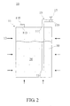
- the heat source 13 can use the surplus heat generated from the adjacent heat generating element. More specifically, as indicated by the arrows shown in FIG. 2 , in an indirect heating manner, the heat source 13 heats the container 11 so as to vaporize the FTBD 20 to generate a vapor pressure in the container 11.
- the heat source 13 can be a high-temperature gas, or even a fluid delivering system 10 disposed in the environment with high temperatures for raising the temperature of the FTBD 20.
- the surplus heat or water with high temperature generated from various electric appliances, vehicles or factories can be reused.
- the heat source 13 can be selected from a group consisting of thermocouple wires, heating bands, electric heaters, hot baths, hot gases, and combinations thereof, wherein hot gases include the exhausted gases generated during the operation of equipments or the gases generated from chemical reactions.
- hot gases include the exhausted gases generated during the operation of equipments or the gases generated from chemical reactions.
- Those skilled in the art can substitute the heat source 13 using any conventional technique that is not limited herein.
- the FTBD 20 in the container 11 can be partially vaporized to provide the needed vapor pressure.
- the heat needed for elevating the vapor pressure is not that much due to the small fluid delivering system 10.
- heat from an electric apparatus, chemical reactions or combustion can be used to heat the fluid delivering system 10 of the present invention.
- the FTBD 20 can be, but is not limited to, water, methanol and/or ethanol.
- the FTBD 20 can also be gasoline or diesel fuel.
- the delivering system of the present invention can be utilized to stably deliver a fluid.
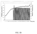
- a container having a delivery pipe with a metering valve and containing 100 ml methanol, was disposed in hot baths for being gradually heated, wherein the container was equipped with a thermal couple and a pressure meter for recording the temperature of the methanol and pressure inside the container.
- the capacity of the container was 160 ml.
- the curve line presents the temperature of the methanol and the bars presents the flow rate of the discharged methanol.
- methanol started to be discharged as its temperature was raised above 65 °C. When the temperature of methanol was gradually raised, the vapor pressure inside the container was also elevated.
- the metering valve methanol was delivered by the above described fluid delivering system at a rate of approximately 0.5 c.c./min stably and steadily.
- FIG. 2 Another preferred embodiment of the present invention is shown in FIG. 2 .
- the auxiliary liquid 30, which is immiscible with the FTBD 20 can be added into the containing space. It is preferred for the auxiliary liquid 30 to possess a boiling point lower than that of the FTBD 20. When the heat source 13 is applied, the temperatures of the FTBD 20 and the auxiliary liquid 30 are raised. Because the auxiliary liquid 30 possesses a lower boiling point, it will be vaporized prior to the FTBD 20 and will elevate the auxiliary vapor pressure in the containing space for delivering the FTBD 20. The auxiliary liquid 30 can boost up the vapor pressure to overcome potential back pressure resistance in the downstream or to allow a higher pressure operation in the downstream process.
- the liquid should either have lower boiling point and be immiscible with the FTBD 20 or, preferably, have a gravity smaller than that of the FTBD 20 to float above the FTBD 20 without being delivered along with it. If the gravity of auxiliary liquid 30 is larger than that of the FTBD 20, the inlet end of the delivery tube 15 should be disposed slightly above the bottom of the container 11.
- Another preferred option for the auxiliary liquid 30 can be one that forms an azeotrope with the FTBD 20. Because the azeotrope has a boiling point lower than that of the FTBD 20 and the auxiliary liquid 30, it will facilitate the formation of vapor pressure in the container 11 for delivering the FTBD 20.
- an auxiliary liquid 30 with high volatility such as pentane, cyclopentane, hexane, and/or cyclohexane can be adopted, while the FTBD 20 is methanol and/or ethanol.
- an auxiliary liquid such as methanol, isopropanol, and/or dichloromethane can be adopted, while the FTBD 20 is gasoline or diesel fuel. Since the gravity of dichloromethane is larger, the first end 151 of the delivery tube 15 should not be touching the bottom of the container 11 so as to prevent the auxiliary liquid 30 from being discharged out of the system.
- the fluid to be delivered the auxiliary liquid azeotropic temperature (°C) water (H 2 O) pentane (C 5 H 12 ) 34.6 methanol (CH 3 OH) pentane (C 5 H 12 ) 30.9 methanol (CH 3 OH) cyclopentane (C 5 H 10 ) 38.8 methanol (CH 3 OH) hexane (C 6 H 14 ) 50.6 methanol (CH 3 OH) cyclohexane (C 6 H 12 ) 54.2
- the azeotropic temperature can be lowered to 38.8°C.
- the FT BD 20 is methanol and the auxiliary liquid 30 is pentane
- the azeotropic temperature can be lowered to 30.9°C.
- auxiliary liquid 30 is needed in the containing space of the container 11.
- the quantity of the added auxiliary liquid 30 is relatively low and does not effect the concentration of the FTBD 20 substantially.
- a fluid delivering system 10 has a container 11 with a 1 litre containing space
- the FTBD 20 is methanol
- the auxiliary liquid 30 is pentane (C 5 H 12 )
- the azeotrope is vaporized to generate a pressure of 2 atmA in the container 11.
- the added pentane should approximately be 5 to 10 grams.
- pentane is only a very small percentage of the discharged fluid.
- the formed azeotrope will contain less than 0.37 grams of methanol. In other words, most of the initially added methanol will be no longer remaining in the system.
- a fluid delivering kit comprises the container 11, the delivery tube 15 and the auxiliary liquid 30 described hereinbefore.
- the kit can be used to deliver fluids.
- the auxiliary liquid 30 can be added into the containing space before, simultaneously, or after the FTBD 20 is added into the containing space.
- the auxiliary liquid 30 is at least partially vaporized by heating, the auxiliary vapor pressure can be formed in the containing space for providing at least a partial driving pressure to deliver the FTBD.
- the fluid delivering kit disclosed in this embodiment can also comprise the abovementioned control element 17, filling aperture 113 and cover 115 which are not further described herein.
- a pot made of stainless steel with an outer diameter of 60 mm, and a height of 75 mm was filled with 120 milliliter of water and was be disposed in a sink as a hot bath.
- the pot was also disposed with a pressure gauge, a thermometer, and a 1/16 inch capillary outlet for measuring fluid delivery.
- the system was heated from room temperature.
- the measured temperature, pressure and flowing variation was shown in Table 1.
- the pressure was at 1.7 atmA.
- the fluid flow rate from the pot was about 0.32 grams per minute.
- the pot was filled with 120 milliliter of water, with 1 milliliter of pentane as the auxiliary liquid.
- the system was heated from room temperature with being measured in temperature, pressure and flowing variation.
- the vapor pressure was 1.7 atmA.
- the fluid flowing rate from the pot was about 0.33 grams per minute.
- the vapor pressure was 2.5 atmA and the fluid flowing rate was about 0.79 grams per minute.
- a micro-delivery needs not a very high temperature, and the delivering efficiency can be enhanced with the addition of little amount of adequate auxiliary liquid.
- the vapor pressure elevated by the fluid itself or a vapor pressure generated from an auxiliary liquid added thereto can drive the FTBD after the fluid is heated.
- the present invention is especially suitable for deliver fluids in micro-quantities.
- the present invention can deliver a micro-quantity of FTBD with the use of heat available from the environment and without the need of an additional pump.
- the product of the present invention is portable, slim, consumes little energy and is suitable for many applications in liquid delivery.
- FIG. 3 shows the structure of a hydrogen generator of a hydrogen fuel cell applying the present invention for delivering methanol-water to generate hydrogen.
- a methanol container a1 further comprises a methanol filling assembly (including a filling aperture and a cover)
- the methanol-water container a2 further comprises a methanol-water filling assembly (including a filling aperture and a cover).
- a methanol-water delivering tube a22 is disposed to connect the methanol-water container a2 and the reaction zone a3.
- a needle valve a23 is further disposed on the methanol-water delivering tube a22.
- air can be introduced into the methanol container a1 through the air inlet a12 by a micro-compressor or a blower (not shown in the figures). Subsequently, methanol is carried into the oxidation catalyst a31 to perform an oxidation-combustion reaction.
- the heat generated from the reaction can not only raise the temperature of the reaction zone a3 but also raise the temperature of the methanol-water container a2.
- vapor pressure is elevated in the methanol-water container a2 to deliver the methanol-water from the methanol-water container a2 to the reaction zone a3 through the methanol-water delivering tube a22 and the needle valve a23.
- the methanol-water then performs a steam reforming reaction in the reaction zone a3, and generates hydrogen for the fuel cell.
- the abovementioned micro-compressor or the blower can use the existing facilities in the electric products.
- a small quantity of methanol-water can be stably delivered without additional pumps.
- the performing results of the assembly shown in FIG. 3 are illustrated as below.
- the system was designed in a size of only 1000 cubic centimeters, i.e., of the same volume as a cube with 10 cm edges.
- Heat generated from the methanol oxidation-combustion raised the temperature of the reaction zone a3 from room temperature to 260 degrees centigrade in approximate 5 minutes, and raised the temperature of methanol-water container a2 as well.
- the needle valve a23 was adjusted to control the flow rate of the methanol-water to the reaction zone a3 for generating hydrogen.
Landscapes
- Engineering & Computer Science (AREA)
- Chemical & Material Sciences (AREA)
- Chemical Kinetics & Catalysis (AREA)
- Sustainable Development (AREA)
- Sustainable Energy (AREA)
- Manufacturing & Machinery (AREA)
- Life Sciences & Earth Sciences (AREA)
- Electrochemistry (AREA)
- General Chemical & Material Sciences (AREA)
- Combustion & Propulsion (AREA)
- Mechanical Engineering (AREA)
- General Engineering & Computer Science (AREA)
- Loading And Unloading Of Fuel Tanks Or Ships (AREA)
- Fuel Cell (AREA)
- Jet Pumps And Other Pumps (AREA)
Applications Claiming Priority (1)
| Application Number | Priority Date | Filing Date | Title |
|---|---|---|---|
| CN200610168908.9A CN101196272B (zh) | 2006-12-08 | 2006-12-08 | 便携式流体输送系统及套件 |
Publications (2)
| Publication Number | Publication Date |
|---|---|
| EP1930647A2 true EP1930647A2 (de) | 2008-06-11 |
| EP1930647A3 EP1930647A3 (de) | 2010-12-29 |
Family
ID=39145220
Family Applications (1)
| Application Number | Title | Priority Date | Filing Date |
|---|---|---|---|
| EP07116243A Withdrawn EP1930647A3 (de) | 2006-12-08 | 2007-09-12 | Tragbares System und Kit zur Abgabe von Flüssigkeiten |
Country Status (2)
| Country | Link |
|---|---|
| EP (1) | EP1930647A3 (de) |
| CN (1) | CN101196272B (de) |
Cited By (1)
| Publication number | Priority date | Publication date | Assignee | Title |
|---|---|---|---|---|
| US20180084945A1 (en) * | 2015-12-29 | 2018-03-29 | Foods-I Co., Ltd. | Barbecue grill and cooking method using barbecue grill |
Families Citing this family (1)
| Publication number | Priority date | Publication date | Assignee | Title |
|---|---|---|---|---|
| CN106379337A (zh) * | 2016-11-02 | 2017-02-08 | 上海钧希新能源科技有限公司 | 一种基于轨道式列车的甲醇空调的甲醇补给系统 |
Family Cites Families (3)
| Publication number | Priority date | Publication date | Assignee | Title |
|---|---|---|---|---|
| JP2006004868A (ja) * | 2004-06-21 | 2006-01-05 | Sony Corp | 燃料電池システム及び燃料電池起動方法 |
| US7648792B2 (en) * | 2004-06-25 | 2010-01-19 | Ultracell Corporation | Disposable component on a fuel cartridge and for use with a portable fuel cell system |
| CN1998105A (zh) * | 2004-07-08 | 2007-07-11 | 直接甲醇燃料电池公司 | 燃料电池盒和燃料输送系统 |
-
2006
- 2006-12-08 CN CN200610168908.9A patent/CN101196272B/zh not_active Expired - Fee Related
-
2007
- 2007-09-12 EP EP07116243A patent/EP1930647A3/de not_active Withdrawn
Cited By (1)
| Publication number | Priority date | Publication date | Assignee | Title |
|---|---|---|---|---|
| US20180084945A1 (en) * | 2015-12-29 | 2018-03-29 | Foods-I Co., Ltd. | Barbecue grill and cooking method using barbecue grill |
Also Published As
| Publication number | Publication date |
|---|---|
| CN101196272A (zh) | 2008-06-11 |
| EP1930647A3 (de) | 2010-12-29 |
| CN101196272B (zh) | 2015-08-19 |
Similar Documents
| Publication | Publication Date | Title |
|---|---|---|
| US7918370B2 (en) | Portable fluid delivering system and kit | |
| US5937655A (en) | Pressure building device for a cryogenic tank | |
| US9669371B2 (en) | Hydrogen generation systems utilizing sodium silicide and sodium silica gel materials | |
| JP3857137B2 (ja) | 揮発性供給原料供給装置及び供給装置を組み込んだ燃料処理装置 | |
| US9845239B2 (en) | Hydrogen generation systems and methods utilizing sodium silicide and sodium silica gel materials | |
| JP5781940B2 (ja) | エアロゲル触媒を伴う水素発生装置 | |
| CN107746038A (zh) | 氢产生装置 | |
| KR20070085537A (ko) | 수소 발생 에너지 생성장치 | |
| EP1227879A1 (de) | Dampfreformierungsverfahren und vorrichtung mit kohlenwasserstoffcharge | |
| JP2013116471A (ja) | 水素発生燃料電池カートリッジ | |
| GB2438807A (en) | Vaporizer and method of vaporizing a liquid for thin film delivery | |
| EP1930647A2 (de) | Tragbares System und Kit zur Abgabe von Flüssigkeiten | |
| JP6989879B1 (ja) | 水素生成装置、水素生成システム、原料カートリッジ、及び水素生成方法 | |
| US20070172403A1 (en) | Thermal siphon reactor and hydrogen generator having the same | |
| US7044160B1 (en) | Device for supplying the consumers of a fuel cell system with liquid media | |
| US7162149B2 (en) | Gaseous fluid generation system | |
| CA2863839A1 (en) | Hydrogen generation systems and methods utilizing sodium silicide and sodium silica gel materials | |
| TW200414600A (en) | Device and method for heating hydrogen storage container | |
| JP2006275091A (ja) | 水素ガスの供給方法及び液化水素輸送車 | |
| US20090297371A1 (en) | Fluid delivery devices | |
| US20080026266A1 (en) | Fuel gas generation and supply device | |
| JP2003277012A (ja) | 水素生成器への原料供給装置及び方法 | |
| JP2003205234A (ja) | ガス発生システムおよび該ガス発生システムを運転するための方法 | |
| JP5125181B2 (ja) | 反応装置及び発電装置並びに反応装置の停止方法 | |
| CN114345155A (zh) | 一种微纳米气泡水生成装置及热水器 |
Legal Events
| Date | Code | Title | Description |
|---|---|---|---|
| PUAI | Public reference made under article 153(3) epc to a published international application that has entered the european phase |
Free format text: ORIGINAL CODE: 0009012 |
|
| AK | Designated contracting states |
Kind code of ref document: A2 Designated state(s): AT BE BG CH CY CZ DE DK EE ES FI FR GB GR HU IE IS IT LI LT LU LV MC MT NL PL PT RO SE SI SK TR |
|
| AX | Request for extension of the european patent |
Extension state: AL BA HR MK RS |
|
| PUAL | Search report despatched |
Free format text: ORIGINAL CODE: 0009013 |
|
| AK | Designated contracting states |
Kind code of ref document: A3 Designated state(s): AT BE BG CH CY CZ DE DK EE ES FI FR GB GR HU IE IS IT LI LT LU LV MC MT NL PL PT RO SE SI SK TR |
|
| AX | Request for extension of the european patent |
Extension state: AL BA HR MK RS |
|
| RIC1 | Information provided on ipc code assigned before grant |
Ipc: H01M 8/06 20060101ALN20101125BHEP Ipc: H01M 8/04 20060101ALI20101125BHEP Ipc: F17C 5/02 20060101AFI20080313BHEP |
|
| AKY | No designation fees paid | ||
| REG | Reference to a national code |
Ref country code: DE Ref legal event code: R108 |
|
| STAA | Information on the status of an ep patent application or granted ep patent |
Free format text: STATUS: THE APPLICATION IS DEEMED TO BE WITHDRAWN |
|
| 18D | Application deemed to be withdrawn |
Effective date: 20110401 |
|
| REG | Reference to a national code |
Ref country code: DE Ref legal event code: R108 Effective date: 20110907 |