EP1930568A1 - Method and system for monitoring process states of an internal combustion engine - Google Patents
Method and system for monitoring process states of an internal combustion engine Download PDFInfo
- Publication number
- EP1930568A1 EP1930568A1 EP06405509A EP06405509A EP1930568A1 EP 1930568 A1 EP1930568 A1 EP 1930568A1 EP 06405509 A EP06405509 A EP 06405509A EP 06405509 A EP06405509 A EP 06405509A EP 1930568 A1 EP1930568 A1 EP 1930568A1
- Authority
- EP
- European Patent Office
- Prior art keywords
- combustion chamber
- exhaust gas
- mass flow
- determining
- composition
- Prior art date
- Legal status (The legal status is an assumption and is not a legal conclusion. Google has not performed a legal analysis and makes no representation as to the accuracy of the status listed.)
- Granted
Links
Images


Classifications
-
- F—MECHANICAL ENGINEERING; LIGHTING; HEATING; WEAPONS; BLASTING
- F02—COMBUSTION ENGINES; HOT-GAS OR COMBUSTION-PRODUCT ENGINE PLANTS
- F02C—GAS-TURBINE PLANTS; AIR INTAKES FOR JET-PROPULSION PLANTS; CONTROLLING FUEL SUPPLY IN AIR-BREATHING JET-PROPULSION PLANTS
- F02C9/00—Controlling gas-turbine plants; Controlling fuel supply in air- breathing jet-propulsion plants
-
- F—MECHANICAL ENGINEERING; LIGHTING; HEATING; WEAPONS; BLASTING
- F01—MACHINES OR ENGINES IN GENERAL; ENGINE PLANTS IN GENERAL; STEAM ENGINES
- F01D—NON-POSITIVE DISPLACEMENT MACHINES OR ENGINES, e.g. STEAM TURBINES
- F01D17/00—Regulating or controlling by varying flow
- F01D17/02—Arrangement of sensing elements
- F01D17/08—Arrangement of sensing elements responsive to condition of working-fluid, e.g. pressure
-
- F—MECHANICAL ENGINEERING; LIGHTING; HEATING; WEAPONS; BLASTING
- F02—COMBUSTION ENGINES; HOT-GAS OR COMBUSTION-PRODUCT ENGINE PLANTS
- F02C—GAS-TURBINE PLANTS; AIR INTAKES FOR JET-PROPULSION PLANTS; CONTROLLING FUEL SUPPLY IN AIR-BREATHING JET-PROPULSION PLANTS
- F02C7/00—Features, components parts, details or accessories, not provided for in, or of interest apart form groups F02C1/00 - F02C6/00; Air intakes for jet-propulsion plants
- F02C7/04—Air intakes for gas-turbine plants or jet-propulsion plants
- F02C7/057—Control or regulation
-
- F—MECHANICAL ENGINEERING; LIGHTING; HEATING; WEAPONS; BLASTING
- F02—COMBUSTION ENGINES; HOT-GAS OR COMBUSTION-PRODUCT ENGINE PLANTS
- F02D—CONTROLLING COMBUSTION ENGINES
- F02D41/00—Electrical control of supply of combustible mixture or its constituents
- F02D41/0002—Controlling intake air
- F02D41/0007—Controlling intake air for control of turbo-charged or super-charged engines
-
- F—MECHANICAL ENGINEERING; LIGHTING; HEATING; WEAPONS; BLASTING
- F02—COMBUSTION ENGINES; HOT-GAS OR COMBUSTION-PRODUCT ENGINE PLANTS
- F02D—CONTROLLING COMBUSTION ENGINES
- F02D41/00—Electrical control of supply of combustible mixture or its constituents
- F02D41/02—Circuit arrangements for generating control signals
- F02D41/14—Introducing closed-loop corrections
- F02D41/1438—Introducing closed-loop corrections using means for determining characteristics of the combustion gases; Sensors therefor
- F02D41/1444—Introducing closed-loop corrections using means for determining characteristics of the combustion gases; Sensors therefor characterised by the characteristics of the combustion gases
- F02D41/1445—Introducing closed-loop corrections using means for determining characteristics of the combustion gases; Sensors therefor characterised by the characteristics of the combustion gases the characteristics being related to the exhaust flow
-
- F—MECHANICAL ENGINEERING; LIGHTING; HEATING; WEAPONS; BLASTING
- F02—COMBUSTION ENGINES; HOT-GAS OR COMBUSTION-PRODUCT ENGINE PLANTS
- F02D—CONTROLLING COMBUSTION ENGINES
- F02D41/00—Electrical control of supply of combustible mixture or its constituents
- F02D41/02—Circuit arrangements for generating control signals
- F02D41/14—Introducing closed-loop corrections
- F02D41/1438—Introducing closed-loop corrections using means for determining characteristics of the combustion gases; Sensors therefor
- F02D41/1444—Introducing closed-loop corrections using means for determining characteristics of the combustion gases; Sensors therefor characterised by the characteristics of the combustion gases
- F02D41/1446—Introducing closed-loop corrections using means for determining characteristics of the combustion gases; Sensors therefor characterised by the characteristics of the combustion gases the characteristics being exhaust temperatures
- F02D41/1447—Introducing closed-loop corrections using means for determining characteristics of the combustion gases; Sensors therefor characterised by the characteristics of the combustion gases the characteristics being exhaust temperatures with determination means using an estimation
-
- F—MECHANICAL ENGINEERING; LIGHTING; HEATING; WEAPONS; BLASTING
- F02—COMBUSTION ENGINES; HOT-GAS OR COMBUSTION-PRODUCT ENGINE PLANTS
- F02D—CONTROLLING COMBUSTION ENGINES
- F02D41/00—Electrical control of supply of combustible mixture or its constituents
- F02D41/02—Circuit arrangements for generating control signals
- F02D41/18—Circuit arrangements for generating control signals by measuring intake air flow
-
- F—MECHANICAL ENGINEERING; LIGHTING; HEATING; WEAPONS; BLASTING
- F02—COMBUSTION ENGINES; HOT-GAS OR COMBUSTION-PRODUCT ENGINE PLANTS
- F02D—CONTROLLING COMBUSTION ENGINES
- F02D2200/00—Input parameters for engine control
- F02D2200/02—Input parameters for engine control the parameters being related to the engine
- F02D2200/10—Parameters related to the engine output, e.g. engine torque or engine speed
- F02D2200/1002—Output torque
- F02D2200/1004—Estimation of the output torque
-
- F—MECHANICAL ENGINEERING; LIGHTING; HEATING; WEAPONS; BLASTING
- F02—COMBUSTION ENGINES; HOT-GAS OR COMBUSTION-PRODUCT ENGINE PLANTS
- F02D—CONTROLLING COMBUSTION ENGINES
- F02D41/00—Electrical control of supply of combustible mixture or its constituents
- F02D41/02—Circuit arrangements for generating control signals
- F02D41/14—Introducing closed-loop corrections
- F02D41/1438—Introducing closed-loop corrections using means for determining characteristics of the combustion gases; Sensors therefor
- F02D41/1444—Introducing closed-loop corrections using means for determining characteristics of the combustion gases; Sensors therefor characterised by the characteristics of the combustion gases
- F02D41/1446—Introducing closed-loop corrections using means for determining characteristics of the combustion gases; Sensors therefor characterised by the characteristics of the combustion gases the characteristics being exhaust temperatures
-
- F—MECHANICAL ENGINEERING; LIGHTING; HEATING; WEAPONS; BLASTING
- F02—COMBUSTION ENGINES; HOT-GAS OR COMBUSTION-PRODUCT ENGINE PLANTS
- F02D—CONTROLLING COMBUSTION ENGINES
- F02D41/00—Electrical control of supply of combustible mixture or its constituents
- F02D41/02—Circuit arrangements for generating control signals
- F02D41/14—Introducing closed-loop corrections
- F02D41/1497—With detection of the mechanical response of the engine
-
- F—MECHANICAL ENGINEERING; LIGHTING; HEATING; WEAPONS; BLASTING
- F05—INDEXING SCHEMES RELATING TO ENGINES OR PUMPS IN VARIOUS SUBCLASSES OF CLASSES F01-F04
- F05D—INDEXING SCHEME FOR ASPECTS RELATING TO NON-POSITIVE-DISPLACEMENT MACHINES OR ENGINES, GAS-TURBINES OR JET-PROPULSION PLANTS
- F05D2260/00—Function
- F05D2260/80—Diagnostics
-
- F—MECHANICAL ENGINEERING; LIGHTING; HEATING; WEAPONS; BLASTING
- F05—INDEXING SCHEMES RELATING TO ENGINES OR PUMPS IN VARIOUS SUBCLASSES OF CLASSES F01-F04
- F05D—INDEXING SCHEME FOR ASPECTS RELATING TO NON-POSITIVE-DISPLACEMENT MACHINES OR ENGINES, GAS-TURBINES OR JET-PROPULSION PLANTS
- F05D2270/00—Control
- F05D2270/30—Control parameters, e.g. input parameters
- F05D2270/303—Temperature
-
- Y—GENERAL TAGGING OF NEW TECHNOLOGICAL DEVELOPMENTS; GENERAL TAGGING OF CROSS-SECTIONAL TECHNOLOGIES SPANNING OVER SEVERAL SECTIONS OF THE IPC; TECHNICAL SUBJECTS COVERED BY FORMER USPC CROSS-REFERENCE ART COLLECTIONS [XRACs] AND DIGESTS
- Y02—TECHNOLOGIES OR APPLICATIONS FOR MITIGATION OR ADAPTATION AGAINST CLIMATE CHANGE
- Y02T—CLIMATE CHANGE MITIGATION TECHNOLOGIES RELATED TO TRANSPORTATION
- Y02T10/00—Road transport of goods or passengers
- Y02T10/10—Internal combustion engine [ICE] based vehicles
- Y02T10/12—Improving ICE efficiencies
Landscapes
- Engineering & Computer Science (AREA)
- Chemical & Material Sciences (AREA)
- Combustion & Propulsion (AREA)
- Mechanical Engineering (AREA)
- General Engineering & Computer Science (AREA)
- Control Of Turbines (AREA)
- Engine Equipment That Uses Special Cycles (AREA)
- Testing Of Engines (AREA)
- Supercharger (AREA)
- Combined Controls Of Internal Combustion Engines (AREA)
Abstract
Description
- The present invention relates to the field of control and instrumentation technology for internal combustion engines. Specifically, the present invention relates to the field of control and instrumentation technology for rotating machines. More specifically, the invention relates to method and a system for monitoring process states of a rotating machine with a combustion chamber, particularly a turbo machine such as a gas turbine.
- Internal combustion engines, in particular rotating machines, e.g. turbo machines such as gas turbines, or reciprocating machines, e.g. diesel engines, are subject to considerable loads. Creep and fatigue affect the machines in extreme conditions owing to very high combustion temperatures, pressure ratios, and air flows. As a consequence of their deterioration, the main components of a gas turbine (GT), i.e. the inlet nozzle, the compressor, the combustion chamber, the turbine, the air flow cooler, and the outlet, all contribute - to a different extent - to the degradation of GT performance. The condition of each single component invariably deteriorates with operation time, until it is at least partially restored by some maintenance action.
- The goal of gas turbine performance diagnosis is to accurately detect, isolate and assess performance changes, system malfunctions and instrumentation problems. Among a number of other techniques, Gas Path Analysis (GPA), as disclosed for instance in
EP-A 1 233 165 , is a well established framework for estimating shifts in performance from the knowledge of measured parameters, such as power, engine speeds, temperatures, pressures or fuel flow, taken along the gas path of the turbine. Discernable shifts in these measured parameters provide the required information for determining the underlying shift in engine operation from a presumed reference, nominal or initial state, i.e. the degradation symptoms. GPA allows engine performance deterioration to be identified in terms of a degradation of independent parameters or system states such as thermodynamic efficiencies, flow capacities and inlet/outlet filter areas. In a subsequent diagnosis step, these degradation symptoms are analysed and a maintenance action schedule is deduced, for ensuring economic and safe operation, or a prediction of the remaining life of the major components is made. The origin of a fault affecting a given component of the gas turbine can be of various natures, such as a contamination of compressor blades, erosion of turbine blades or corrosion of machine parts, for example. Conversely, different faults often create similar observable effects or degradation symptoms. - Accordingly, for the operation of a GT, it is important to know exactly the main process states such as temperatures, pressures or fluid mass flow, before and after each component. Specifically, the turbine inlet temperature is constrained to an upper limit, as high temperatures let the turbine blades deteriorate faster than lower temperatures, thereby reducing the life time of the GT. On the other hand, for fuel efficient operation of a GT, high temperatures are required. Therefore, the turbine inlet temperature is controlled tightly. However, in many GT's the turbine inlet temperature is not measured but derived from other measurable states, which produces uncertainty on the controlled variable. Reliable methods to derive turbine inlet temperatures are therefore crucial for operating a GT efficiently. Precise knowledge of these unmeasured states makes it possible to better estimate the operating conditions and, therefore, to better predict maintenance scheduling.
- Typically, conventional methods of determining unknown process states use a dynamic or static model. These models are based on thermodynamic and fluid mechanical principles. Model-based techniques make often use of Kalman filter techniques for the online estimation of the unknown states or use iterative methods (e.g. Newton-Raphson), such as described in
EP 1 233 165 - It is therefore an objective of the present invention to provide an improved method and an improved system for monitoring unmeasured process states of an internal combustion engine, in particular of a rotating machine having a combustion chamber, and more particularly, a turbo machine such as a gas turbine. It is a particular objective of the present invention, to provide a method and a system for determining more accurately than with conventional methods the turbine inlet temperature of a gas turbine. It is another objective of the present invention, to determine further unmeasured process states such as air mass flow, exhaust gas mass flow and turbine inlet pressure, important for assessing efficiency of the gas turbine.
- At least some of these objectives are achieved by a method of and a system for monitoring process states of an internal combustion engine, in particular of a rotating machine, according to
claim 1 and claim 7 respectively, as well as by a use of the method according to claim 10. Further preferred embodiments are evident from the dependent claims. - According to the present invention, the above-mentioned objects are particularly achieved in that, for monitoring (unmeasured) process states of a rotating machine having a combustion chamber, measured are compositions of educts entering the combustion chamber. Based on the compositions of the educts, determined is the composition of the product produced by the combustion chamber. Moreover, determined is the mechanical power generated by the rotating machine. Specifically, the mechanical power is determined based on characteristics of a generator driven by the rotating machine and based on the measured power generated by the generator. Based on the mechanical power, the composition of the educts and product, and stoichiometric relationships of educts and product, the value of at least one of the process states is determined and, for example, displayed and/or provided to a control unit controlling the rotating machine.
- Thus, based on precise measurements of the educt, e.g. the composition of air and fuel in the combustion process, the product, i.e. the composition of the exhaust gas, is derived, assuming complete combustion, which is very reasonable at least for gaseous fuel. Subsequently, without the need of an iterative or recursive method, making possible a more robust and faster implementation, various unmeasured process states can be determined, e.g. the air mass flow through the compressor leading into the combustion chamber and/or a gas mass flow, a composition and/or a temperature of exhaust gas exiting the combustion chamber. Particularly, in addition to monitoring unmeasured process states, e.g. through implementation on an industrial control system, it is possible to control the turbine inlet temperature based on a more accurate estimate thereof. The proposed method and system are applicable to any rotating machinery where combustion is involved, e.g. a gas turbine, a diesel engine, an internal combustion engine, etc.
- For example, for monitoring the process states of a gas turbine, determined is the air mass flow through the compressor leading into the combustion chamber. Based on the air mass flow and the fuel mass flow into the combustion chamber, determined is the gas mass flow of exhaust gas exiting the combustion chamber. Based on the air mass flow and the gas mass flow, determined is the composition of the exhaust gas. Based on the air mass flow, the gas mass flow, and the composition of the exhaust gas, determined is the temperature of the exhaust gas exiting the combustion chamber. The temperature of the exhaust gas exiting the combustion chamber is representative of the inlet temperature of the turbine that is driven by the exhaust gas exiting the combustion chamber.
- Preferably, temperatures of educts and product are measured, and, based on their respective temperatures, enthalpies for educts and product are determined using enthalpy functions associated with their respective compositions. In the example of monitoring the process states of the gas turbine, measured are the temperatures of air and fuel entering the combustion chamber, and the temperature of the exhaust gas exiting the turbine. Subsequently, enthalpies for air, fuel and exhaust gas are determined based on their respective temperatures, and the value of the at least one of the process states is based on the enthalpies.
- In an embodiment, determined is an inverted enthalpy function associated with the composition of the exhaust gas. Subsequently, the temperature of the exhaust gas exiting the combustion chamber is determined based on the air mass flow and the gas mass flow using the inverted enthalpy function.
- The present invention will be explained in more detail, by way of example, with reference to the drawings in which:
-
Fig. 1 shows a block diagram illustrating schematically a gas turbine and its main process states, -
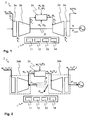
Fig. 2 shows a block diagram illustrating schematically thermodynamic boundaries of the gas turbine, -
Fig. 3 shows an exemplary sequence of steps for monitoring process states of a rotating machine having a combustion chamber, -
Fig. 4 depicts compound enthalpies for four distinct gas compositions, and -
Fig. 5 depicts how a turbine inlet temperature is determined from an enthalpy line. -
Fig. 1 shows the principal components of arotating machine 2, particularly a gas turbine, viewed as a system consisting of a sequential arrangement of ideal volume elements in thermodynamic equilibrium,i.e. compressor inlet 2a (filter, nozzle),compressor 2b,combustion chamber 2c,turbine 2d andoutlet conduit 2e, whereincompressor 2b andturbine 2d are mechanically interconnected by ashaft 2f.Fig.1 also depicts the places where the various dependent or system output variables, i.e. the process variables such as temperatures, pressures, power and shaft speed, are measured. These variables comprise the temperature T0 at the entry to thecompressor inlet 2a, as well as the compressor inlet and outlet temperature and pressure denoted T1 , p1 and T2, p2 , respectively. Further along the gas path, turbine inlet and outlet temperature and pressure are denoted T3, p3 and T4, p4, respectively, whereas the exhaust gas finally has a variable temperature T5 and a pressure p5 (usually p5 can be assumed to be equal to the ambient pressure p0 ). In addition, the shaft speed N, mechanical power Pmech and generator power Pgen are typical output variables. InFigs. 1 and 2 , indices a, f, g, and w refer to air, fuel, exhaust gas, or water, respectively. Thus reference numerals wa, wf, wg, ww refer to air mass flow, fuel mass flow, exhaust gas mass flow, or water mass flow, respectively; reference numerals m a , m f , m g, m w refer to the specific compositions of air, fuel, exhaust gas, or water, respectively; and reference numerals ha, hf, hg refer to the enthalpy at specific temperatures Ti of air, fuel, or exhaust gas, respectively. - Typically, the main unmeasured process states used to monitor and/or control efficient operation include the turbine inlet temperature T3, the air mass flow wa, and the exhaust gas mass flow wg. Often the turbine inlet pressure p3 is also determined. Additionally, the exhaust gas composition may be of interest for regulatory reasons (e.g. CO2 emission). These unmeasured process states are derived from the measurable states, as will be explained in the following paragraphs.
-
Fig. 2 shows schematically the thermodynamic system boundaries 2ab, 2de of the gas turbine, boundary 2ab encompassingcompressor inlet 2a andcompressor 2b, and boundary2de encompassing turbine 2d andoutlet conduit 2e. - Generally, the losses can be quantified with sufficient accuracy and are combined and described by one power term Ploss which is assumed to be known. The mechanical power Pmech generated by the
turbine 2d is derived, for example, from the generator characteristics and the measured generator power Pgen. Using the system boundaries as defined inFig. 2 , the following relations can be derived:


- The enthalpies for air, fuel and exhaust gas, h (·)(T (·)), can be derived by considering their specific composition m (·) and by using the enthalpy functions h (·) (T (·)) published by NASA as polynomials which describe the enthalpy of the main elements. The polynomials are taken from http://cea.grc.nasa.gov/, which is a tool provided by the NASA Glenn Research Center under the title "Chemical Equilibrium with Applications". The desired polynomials are generated and downloaded as

- These enthalpy functions are polynomials of higher order and are only temperature dependent.
Fig. 4 depicts examples of compound enthalpies h(T) for four distinct gas compositions, as obtained from the NASA site. In equation (3), the terms wg ·[h g(T 3)-h g(T 4)] and wa are unknown, as wg, T3 and m g are unknown. In a first step, wa is derived. With reference toFig. 2 , the product w g h g(T 3) is calculated from the enthalpies that enter the combustion process. Hence,
- While the GT is operated with gas, the water injection (ww ) is neglected in the present example. However, one skilled in the art will understand that the equations can be extended easily to include the water injection. Likewise, pressures and flow speeds are not incorporated, but could be included in a corresponding extension. The term Δhf is the heating value (or heat rate) of the fuel gas and can be calculated from the enthalpy of formation (according to Hess's law) of each gas component (Δ h ). Hence,

- The exhaust gas enthalpy flow after the turbine is w g h g(T4 ). Hence,


- Whereby V is the combustion matrix describing the stoichiometric relation for each component. For example, the complete combustion of Methene and Ethene is covered by the following matrix calculation:


- The vector M contains the corresponding molar masses and diag( M ) is a matrix with the elements of M on its diagonal. The first row in V can be read as the amount of O2 molecules in the educt minus two times amount of CH4 molecules minus 2.5 times the amount of C2H6 molecules yields the amount of O2 molecules in the product. Correspondingly, the second row reads as the amount of CO2 in the educt plus once the amount of molecules of CH4 plus twice the amount of molecules of C2H6 yields the CO2 amount in the product. Hence, equation (3) can be rewritten as


- All variables on the right hand side are known. Subsequently, the exhaust gas flow is derived as


- Because the enthalpy functions are monotonic (and therefore invertible), the turbine inlet temperature T3 can be derived easily by inverting the corresponding enthalpy function from equation (5):

- The inversion is schematically depicted in
Fig. 5 , where (due to monotonicity) the temperature T3 is found corresponding to a particular enthalpy. Five distinct enthalpy lines for constant exhaust gas compositions are depicted (broken lines), one of them being approximated by a 2nd order polynominal h'g in the relevant temperature range between 1000 and 1500 K (shaded area). As the approximation is seen to work reasonably well, in practice, the interpolating low order polynomials are inverted for the purpose of deriving T3. - The method is implemented, for example, on an
industrial control system 1 for monitoring the unmeasured process states and/or for controlling the turbine inlet temperature T3 . Due to the fact that the combustion is taken into account, CO2 emissions can be derived directly through the calculation. Furthermore, the method can be extended for supervising the quality of fuel input. Properties of specific gas components, such as CO2 or NOx, are often measured in the exhaust gas for regulatory reasons. Having available both, a measurement and an estimation (based on the above determination), provides information on the quality of combustion, quality of fuel input and/or sensor failure, leading to enhanced diagnostics of the combustion system. - For example, the
system 1 comprises asensor module 11 for receiving measurements of process variables and/or educt composition(s); a data andprogram memory 12 for storing measurement values, calculation parameters and programmed software modules; aprocessing unit 13 with at least one processor; and anoutput module 14 for displaying processing states and/or for proving, to thegas turbine 2 or to a control unit controlling thegas turbine 2, control signals based on the derived processing states. In an embodiment, theprogram memory 12 comprises a programmed software module for controlling the processing unit such that the method is executed as described in the following paragraphs with reference toFig. 3 . - In step S1, measurements are taken and respective measurement values are received by
sensor module 11 and stored in thesystem 1. - In step S2, the
processing unit 13 computes the air mass flow wa using equation (12), as described above. - In step S3, the
processing unit 13 computes the exhaust gas mass flow wg and exhaust gas composition m g using equations (13) or (14), respectively. - In step S4, the
processing unit 13 computes the enthalpy inversion
- In step S5, the
processing unit 13 computes the turbine inlet temperature T3 using equation (15) as described above. - As is also illustrated in
Fig. 3 , the computer process states, e.g. the air mass flow wa , the exhaust gas mass flow wg , the exhaust gas composition m g , and/or the turbine inlet temperature T3 , are used by theoutput module 14 for applications of performance evaluation A1, combustion/emission control A2, and/or turbine control A3.
Claims (10)
- A method of monitoring process states of an internal combustion engine, in particular of a rotating machine (2) having a combustion chamber (2c), the method comprising:measuring compositions of educts (m a, m f) entering the combustion chamber (2c);determining based on the compositions of the educts (m a, m f) a composition of a product (m g) produced by the combustion chamber (2c);determining mechanical power (Pmech) generated by the rotating machine (2); anddetermining a value of at least one of the process states based on the mechanical power (Pmech), the composition of the educts (m a, m f) and product (m g), and stoichiometric relationships of educts and product.
- The method according to claim 1, wherein determining the value of the at least one of the process states includes determining at least one of an air mass flow (wa) through a compressor (2b) leading into the combustion chamber (2c), and a gas mass flow (wg), a composition (m g) and a temperature (T3) of exhaust gas exiting the combustion chamber (2c) and/or entering a turbine (2d).
- The method according to claim 1, further comprising measuring temperatures of educts and product, and determining enthalpies (ha, hf, hg) for educts and product using enthalpy functions associated with their respective compositions (m a, m f, m g), wherein determining the enthalpies (ha, hf, hg) for educts and product is based on their respective temperatures, and wherein determining the value of the at least one of the process states is based on the enthalpies (ha, hf, hg).
- The method according to claim 1, wherein monitoring the process states includes monitoring the process states of a gas turbine, and wherein determining the value of the at least one of the process states includes determining an air mass flow (wa) through a compressor (2b) leading into the combustion chamber (2c), determining a gas mass flow (wg) of exhaust gas exiting the combustion chamber (2c) based on the air mass flow (wa) and a fuel mass flow (wf) into the combustion chamber (2c), determining a composition of the exhaust gas (m g) based on the air mass flow (wa) and the gas mass flow (wg), and determining a temperature (T3) of the exhaust gas exiting the combustion chamber (2c) based on the air mass flow (wa), the gas mass flow (wg), and the composition of the exhaust gas (m g), the temperature (T3) of the exhaust gas exiting the combustion chamber (2c) being representative of an inlet temperature of the turbine driven by the exhaust gas exiting the combustion chamber (2c).
- The method according to claim 4, wherein determining the temperature (T3) of the exhaust gas includes determining an inverted enthalpy function associated with the composition of the exhaust gas (m g), and determining the temperature (T3) of the exhaust gas exiting the combustion chamber (2c) is based on the air mass flow (wa) and the gas mass flow (wg) using the inverted enthalpy function.
- The method according to claim 4, further comprising measuring temperatures (T2, Tf) of air and fuel entering the combustion chamber (2c), measuring the temperature (T4) of the exhaust gas exiting the turbine, and determining enthalpies (ha, hf, hg) for air, fuel and exhaust gas based on their respective temperatures, and wherein determining the value of the at least one of the process states is based on the enthalpies (ha, hf, hg).
- A system (1) for monitoring process states of an internal combustion engine, in particular of a rotating machine (2) having a combustion chamber (2c), the system (1) comprising:means for measuring compositions of educts (m a, m f) entering the combustion chamber (2c);means for determining based on the compositions of the educts (m a, m f) a composition of a product (m g) produced by the combustion chamber (2c);means for determining mechanical power (Pmech) generated by the rotating machine (2); andmeans for determining a value of at least one of the process states based on the mechanical power (Pmech), the composition of the educts (m a, m f) and product (m g), and stoichiometric relationships of educts and product.
- The system (1) according to claim 7, wherein the rotating machine (2) is a gas turbine, wherein the process states include at least one of an air mass flow (wa) through a compressor (2b) leading into the combustion chamber (2c), and a gas mass flow (wg), a composition (m g) and a temperature (T3) of exhaust gas exiting the combustion chamber (2c), and wherein the means for determining the value of the at least one of the process states are further configured to determine an air mass flow (wa) through a compressor (2b) leading into the combustion chamber (2c), to determine a gas mass flow (wg) of exhaust gas exiting the combustion chamber (2c) based on the air mass flow (wa) and a fuel mass flow (wf) into the combustion chamber (2c), to determine a composition of the exhaust gas (m g) based on the air mass flow (wa) and the gas mass flow (wg), and to determine a temperature (T3) of the exhaust gas exiting the combustion chamber (2c) based on the air mass flow (wa), the gas mass flow (wg), and the composition of the exhaust gas (m g), the temperature (T3) of the exhaust gas exiting the combustion chamber (2c) being representative of an inlet temperature of the turbine driven by the exhaust gas exiting the combustion chamber (2c).
- The system (1) according to claim 8, further comprising means for measuring temperatures (T2, Tf) of air and fuel entering the combustion chamber (2c), means for measuring the temperature (T4) of the exhaust gas exiting the turbine, and means for determining enthalpies (ha, hf, hg) for air, fuel and exhaust gas based on their respective temperatures, and wherein the means for determining the value of the at least one of the process states are configured to determine the value of the at least one of the process states based on the enthalpies (ha, hf, hg).
- A use of a method of monitoring process states as claimed in one of claims 1 to 6 for the purpose of diagnosing the internal combustion system, comprising determining the composition (m g) of the exhaust gas as a process state, measuring properties of specific exhaust gas components by means of sensors, deriving, from the determined composition and the measured properties, information on a quality of combustion or a quality of fuel input, or information about sensor failure.
Priority Applications (7)
| Application Number | Priority Date | Filing Date | Title |
|---|---|---|---|
| EP06405509A EP1930568B1 (en) | 2006-12-07 | 2006-12-07 | Method and system for monitoring process states of an internal combustion engine |
| ES06405509T ES2347345T3 (en) | 2006-12-07 | 2006-12-07 | METHOD AND SYSTEM FOR SUPERVISING PROCESS STATES OF A COMBUSTION ENGINE. |
| DE602006015490T DE602006015490D1 (en) | 2006-12-07 | 2006-12-07 | Method and system for monitoring the operating status of an internal combustion engine |
| AT06405509T ATE474133T1 (en) | 2006-12-07 | 2006-12-07 | METHOD AND SYSTEM FOR MONITORING THE OPERATING STATUS OF AN INTERNAL COMBUSTION ENGINE |
| CN2007800454981A CN101595288B (en) | 2006-12-07 | 2007-12-07 | Method and system for monitoring process states of an internal combustion engine |
| PCT/EP2007/063518 WO2008068330A1 (en) | 2006-12-07 | 2007-12-07 | Method and system for monitoring process states of an internal combustion engine |
| US12/480,411 US8280647B2 (en) | 2006-12-07 | 2009-06-08 | Method and system for monitoring process states of an internal combustion engine |
Applications Claiming Priority (1)
| Application Number | Priority Date | Filing Date | Title |
|---|---|---|---|
| EP06405509A EP1930568B1 (en) | 2006-12-07 | 2006-12-07 | Method and system for monitoring process states of an internal combustion engine |
Publications (2)
| Publication Number | Publication Date |
|---|---|
| EP1930568A1 true EP1930568A1 (en) | 2008-06-11 |
| EP1930568B1 EP1930568B1 (en) | 2010-07-14 |
Family
ID=38052895
Family Applications (1)
| Application Number | Title | Priority Date | Filing Date |
|---|---|---|---|
| EP06405509A Not-in-force EP1930568B1 (en) | 2006-12-07 | 2006-12-07 | Method and system for monitoring process states of an internal combustion engine |
Country Status (7)
| Country | Link |
|---|---|
| US (1) | US8280647B2 (en) |
| EP (1) | EP1930568B1 (en) |
| CN (1) | CN101595288B (en) |
| AT (1) | ATE474133T1 (en) |
| DE (1) | DE602006015490D1 (en) |
| ES (1) | ES2347345T3 (en) |
| WO (1) | WO2008068330A1 (en) |
Cited By (3)
| Publication number | Priority date | Publication date | Assignee | Title |
|---|---|---|---|---|
| EP3115569A1 (en) * | 2015-07-08 | 2017-01-11 | Volkswagen Aktiengesellschaft | Method for the determination of a gas property of a gas of an internal combustion engine and corresponding engine control unit |
| US9581087B1 (en) * | 2015-09-17 | 2017-02-28 | Siemens Energy, Inc. | Method and system for thermal expansion compensation in heated flow characterization |
| EP2740916A3 (en) * | 2012-12-06 | 2017-08-02 | Honeywell International Inc. | Operations support systems and methods for calculating and evaluating turbine temperatures and health |
Families Citing this family (11)
| Publication number | Priority date | Publication date | Assignee | Title |
|---|---|---|---|---|
| US8504276B2 (en) * | 2008-02-28 | 2013-08-06 | Power Systems Mfg., Llc | Gas turbine engine controls for minimizing combustion dynamics and emissions |
| EP2357339A1 (en) | 2010-02-12 | 2011-08-17 | Siemens Aktiengesellschaft | Method of determining a combustor exit temperature and method of controlling a gas turbine |
| GB201117942D0 (en) | 2011-10-18 | 2011-11-30 | Rolls Royce Goodrich Engine Control Systems Ltd | Fuel system |
| US9790834B2 (en) | 2014-03-20 | 2017-10-17 | General Electric Company | Method of monitoring for combustion anomalies in a gas turbomachine and a gas turbomachine including a combustion anomaly detection system |
| US9791351B2 (en) | 2015-02-06 | 2017-10-17 | General Electric Company | Gas turbine combustion profile monitoring |
| DE102015224078A1 (en) * | 2015-12-02 | 2017-06-08 | Robert Bosch Gmbh | Method and device for determining a fresh air mass flow in an engine system with an internal combustion engine |
| US9915570B1 (en) * | 2016-08-18 | 2018-03-13 | DCIM Solutions, LLC | Method and system for managing cooling distribution |
| US10641185B2 (en) * | 2016-12-14 | 2020-05-05 | General Electric Company | System and method for monitoring hot gas path hardware life |
| CN109341771B (en) * | 2018-11-01 | 2021-01-08 | 中国航空工业集团公司沈阳飞机设计研究所 | Pressure and temperature loss measuring method of pipeline working medium based on generator |
| US11739696B2 (en) * | 2021-12-13 | 2023-08-29 | Pratt & Whitney Canada Corp. | System and method for synthesizing engine output power |
| JP2023166083A (en) * | 2022-05-09 | 2023-11-21 | 三菱重工業株式会社 | Gas turbine control device, gas turbine control method and program |
Citations (6)
| Publication number | Priority date | Publication date | Assignee | Title |
|---|---|---|---|---|
| US3898962A (en) * | 1972-06-02 | 1975-08-12 | Bosch Gmbh Robert | Control system and devices for internal combustion engines |
| US4094142A (en) * | 1974-10-30 | 1978-06-13 | Engelhard Minerals & Chemicals Corp. | Turbine system method and apparatus |
| US4096839A (en) * | 1976-02-24 | 1978-06-27 | Stromberg-Carlson Corporation | Internal combustion engine air-fuel ratio control system utilizing oxygen sensor |
| US4517948A (en) | 1982-08-03 | 1985-05-21 | Nippondenso Co., Ltd. | Method and apparatus for controlling air-fuel ratio in internal combustion engines |
| US4945882A (en) | 1989-06-16 | 1990-08-07 | General Motors Corporation | Multi-fuel engine control with oxygen sensor signal reference control |
| US5157613A (en) * | 1987-01-14 | 1992-10-20 | Lucas Industries Public Limited Company | Adaptive control system for an engine |
Family Cites Families (10)
| Publication number | Priority date | Publication date | Assignee | Title |
|---|---|---|---|---|
| JPS58206838A (en) * | 1982-05-28 | 1983-12-02 | Hitachi Ltd | System for supplying fuel into electronic control cylinder |
| US4692429A (en) * | 1984-04-25 | 1987-09-08 | Research Association Of Electric Conductive Inorganic Compounds | Catalyst composition and multi-functional sensor |
| JPH0367770A (en) * | 1989-08-08 | 1991-03-22 | Akebono Brake Res & Dev Center Ltd | Anti-lock control method for vehicle |
| US6612269B2 (en) * | 2000-08-11 | 2003-09-02 | The Regents Of The University Of California | Apparatus and method for operating internal combustion engines from variable mixtures of gaseous fuels |
| CN1258642C (en) * | 2001-01-02 | 2006-06-07 | 中国船舶重工集团公司第七研究院第七○三研究所 | Boosting system for steaming turbine of IC engine |
| ATE544106T1 (en) * | 2001-02-19 | 2012-02-15 | Abb Schweiz Ag | DETERMINATION OF DEGRADATION OF A GAS TURBINE |
| US6938466B2 (en) * | 2001-11-15 | 2005-09-06 | Delphi Technologies, Inc. | Fuel driveability index detection |
| US6913004B2 (en) * | 2002-03-22 | 2005-07-05 | Chrysalis Technologies Incorporated | Fuel system for an internal combustion engine and method for controlling same |
| CA2441686C (en) * | 2003-09-23 | 2004-12-21 | Westport Research Inc. | Method for controlling combustion in an internal combustion engine and predicting performance and emissions |
| DE10353689A1 (en) * | 2003-11-17 | 2005-06-16 | Audi Ag | Method for determining additional fuel consumption in a motor vehicle and method for displaying the additional fuel consumption |
-
2006
- 2006-12-07 EP EP06405509A patent/EP1930568B1/en not_active Not-in-force
- 2006-12-07 ES ES06405509T patent/ES2347345T3/en active Active
- 2006-12-07 DE DE602006015490T patent/DE602006015490D1/en active Active
- 2006-12-07 AT AT06405509T patent/ATE474133T1/en not_active IP Right Cessation
-
2007
- 2007-12-07 WO PCT/EP2007/063518 patent/WO2008068330A1/en active Application Filing
- 2007-12-07 CN CN2007800454981A patent/CN101595288B/en not_active Expired - Fee Related
-
2009
- 2009-06-08 US US12/480,411 patent/US8280647B2/en not_active Expired - Fee Related
Patent Citations (6)
| Publication number | Priority date | Publication date | Assignee | Title |
|---|---|---|---|---|
| US3898962A (en) * | 1972-06-02 | 1975-08-12 | Bosch Gmbh Robert | Control system and devices for internal combustion engines |
| US4094142A (en) * | 1974-10-30 | 1978-06-13 | Engelhard Minerals & Chemicals Corp. | Turbine system method and apparatus |
| US4096839A (en) * | 1976-02-24 | 1978-06-27 | Stromberg-Carlson Corporation | Internal combustion engine air-fuel ratio control system utilizing oxygen sensor |
| US4517948A (en) | 1982-08-03 | 1985-05-21 | Nippondenso Co., Ltd. | Method and apparatus for controlling air-fuel ratio in internal combustion engines |
| US5157613A (en) * | 1987-01-14 | 1992-10-20 | Lucas Industries Public Limited Company | Adaptive control system for an engine |
| US4945882A (en) | 1989-06-16 | 1990-08-07 | General Motors Corporation | Multi-fuel engine control with oxygen sensor signal reference control |
Cited By (3)
| Publication number | Priority date | Publication date | Assignee | Title |
|---|---|---|---|---|
| EP2740916A3 (en) * | 2012-12-06 | 2017-08-02 | Honeywell International Inc. | Operations support systems and methods for calculating and evaluating turbine temperatures and health |
| EP3115569A1 (en) * | 2015-07-08 | 2017-01-11 | Volkswagen Aktiengesellschaft | Method for the determination of a gas property of a gas of an internal combustion engine and corresponding engine control unit |
| US9581087B1 (en) * | 2015-09-17 | 2017-02-28 | Siemens Energy, Inc. | Method and system for thermal expansion compensation in heated flow characterization |
Also Published As
| Publication number | Publication date |
|---|---|
| CN101595288B (en) | 2011-12-14 |
| EP1930568B1 (en) | 2010-07-14 |
| DE602006015490D1 (en) | 2010-08-26 |
| US8280647B2 (en) | 2012-10-02 |
| US20090281737A1 (en) | 2009-11-12 |
| CN101595288A (en) | 2009-12-02 |
| ES2347345T3 (en) | 2010-10-28 |
| ATE474133T1 (en) | 2010-07-15 |
| WO2008068330A1 (en) | 2008-06-12 |
Similar Documents
| Publication | Publication Date | Title |
|---|---|---|
| EP1930568B1 (en) | Method and system for monitoring process states of an internal combustion engine | |
| EP1705542B1 (en) | Estimating health parameters or symptoms of a degrading system | |
| US6684163B2 (en) | Determination of a degradation of a gas turbine | |
| US8000930B2 (en) | Monitoring a degrading system | |
| RU2658869C2 (en) | Estimation of health parameters in industrial gas turbines | |
| US20170328811A1 (en) | Abnormality diagnosing method and abnormality diagnosing system | |
| EP1114991A2 (en) | Methods and systems for estimating engine faults | |
| Panov | Auto-tuning of real-time dynamic gas turbine models | |
| KR20190003580A (en) | Monitoring device, monitoring method and program of target device | |
| JP2011090382A (en) | Monitoring system | |
| Asgari et al. | Modeling and simulation of the start-up operation of a heavy-duty gas turbine by using NARX models | |
| Panov | Model-based control and diagnostic techniques for operational improvements of gas turbine engines | |
| EP1482150A2 (en) | Method and system of synthesizing turbine inlet temperature of a turbo machine | |
| CN115144186A (en) | Gas turbine engine gas path fault continuous high-precision diagnosis method | |
| US9933336B2 (en) | Gas turbine having fuel monitoring | |
| RU2665142C1 (en) | Method of flight diagnostics of units of turbofan engine with flow mixing | |
| Visser et al. | Experience with gsp as a gas path analysis tool | |
| US8707769B2 (en) | Power plant analyzer for analyzing a plurality of power plants | |
| RU2782090C1 (en) | Method for controlling the temperature of gases downstream of a high-pressure turbine of a gas turbine engine | |
| US20230273095A1 (en) | Successive Gas Path Fault Diagnosis Method with High Precision for Gas Turbine Engines | |
| US20240118171A1 (en) | Plant monitoring method, plant monitoring device, and plant monitoring program | |
| Tsoutsanis et al. | Gas path analysis applied to an aeroderivative gas turbine used for power generation | |
| CN117592263A (en) | Method and device for monitoring stress relaxation of bolt flange connection system |
Legal Events
| Date | Code | Title | Description |
|---|---|---|---|
| PUAI | Public reference made under article 153(3) epc to a published international application that has entered the european phase |
Free format text: ORIGINAL CODE: 0009012 |
|
| AK | Designated contracting states |
Kind code of ref document: A1 Designated state(s): AT BE BG CH CY CZ DE DK EE ES FI FR GB GR HU IE IS IT LI LT LU LV MC NL PL PT RO SE SI SK TR |
|
| AX | Request for extension of the european patent |
Extension state: AL BA HR MK RS |
|
| 17P | Request for examination filed |
Effective date: 20080828 |
|
| 17Q | First examination report despatched |
Effective date: 20081126 |
|
| AKX | Designation fees paid |
Designated state(s): AT BE BG CH CY CZ DE DK EE ES FI FR GB GR HU IE IS IT LI LT LU LV MC NL PL PT RO SE SI SK TR |
|
| GRAP | Despatch of communication of intention to grant a patent |
Free format text: ORIGINAL CODE: EPIDOSNIGR1 |
|
| GRAS | Grant fee paid |
Free format text: ORIGINAL CODE: EPIDOSNIGR3 |
|
| GRAA | (expected) grant |
Free format text: ORIGINAL CODE: 0009210 |
|
| AK | Designated contracting states |
Kind code of ref document: B1 Designated state(s): AT BE BG CH CY CZ DE DK EE ES FI FR GB GR HU IE IS IT LI LT LU LV MC NL PL PT RO SE SI SK TR |
|
| REG | Reference to a national code |
Ref country code: GB Ref legal event code: FG4D |
|
| REG | Reference to a national code |
Ref country code: CH Ref legal event code: EP |
|
| REG | Reference to a national code |
Ref country code: IE Ref legal event code: FG4D |
|
| REF | Corresponds to: |
Ref document number: 602006015490 Country of ref document: DE Date of ref document: 20100826 Kind code of ref document: P |
|
| REG | Reference to a national code |
Ref country code: CH Ref legal event code: NV Representative=s name: ABB SCHWEIZ AG INTELLECTUAL PROPERTY (CH-LC/IP) |
|
| REG | Reference to a national code |
Ref country code: NL Ref legal event code: T3 |
|
| REG | Reference to a national code |
Ref country code: ES Ref legal event code: FG2A Ref document number: 2347345 Country of ref document: ES Kind code of ref document: T3 |
|
| LTIE | Lt: invalidation of european patent or patent extension |
Effective date: 20100714 |
|
| PG25 | Lapsed in a contracting state [announced via postgrant information from national office to epo] |
Ref country code: AT Free format text: LAPSE BECAUSE OF FAILURE TO SUBMIT A TRANSLATION OF THE DESCRIPTION OR TO PAY THE FEE WITHIN THE PRESCRIBED TIME-LIMIT Effective date: 20100714 Ref country code: FI Free format text: LAPSE BECAUSE OF FAILURE TO SUBMIT A TRANSLATION OF THE DESCRIPTION OR TO PAY THE FEE WITHIN THE PRESCRIBED TIME-LIMIT Effective date: 20100714 Ref country code: LT Free format text: LAPSE BECAUSE OF FAILURE TO SUBMIT A TRANSLATION OF THE DESCRIPTION OR TO PAY THE FEE WITHIN THE PRESCRIBED TIME-LIMIT Effective date: 20100714 |
|
| PG25 | Lapsed in a contracting state [announced via postgrant information from national office to epo] |
Ref country code: CY Free format text: LAPSE BECAUSE OF FAILURE TO SUBMIT A TRANSLATION OF THE DESCRIPTION OR TO PAY THE FEE WITHIN THE PRESCRIBED TIME-LIMIT Effective date: 20100714 Ref country code: BG Free format text: LAPSE BECAUSE OF FAILURE TO SUBMIT A TRANSLATION OF THE DESCRIPTION OR TO PAY THE FEE WITHIN THE PRESCRIBED TIME-LIMIT Effective date: 20101014 Ref country code: IS Free format text: LAPSE BECAUSE OF FAILURE TO SUBMIT A TRANSLATION OF THE DESCRIPTION OR TO PAY THE FEE WITHIN THE PRESCRIBED TIME-LIMIT Effective date: 20101114 Ref country code: PL Free format text: LAPSE BECAUSE OF FAILURE TO SUBMIT A TRANSLATION OF THE DESCRIPTION OR TO PAY THE FEE WITHIN THE PRESCRIBED TIME-LIMIT Effective date: 20100714 Ref country code: PT Free format text: LAPSE BECAUSE OF FAILURE TO SUBMIT A TRANSLATION OF THE DESCRIPTION OR TO PAY THE FEE WITHIN THE PRESCRIBED TIME-LIMIT Effective date: 20101115 Ref country code: SI Free format text: LAPSE BECAUSE OF FAILURE TO SUBMIT A TRANSLATION OF THE DESCRIPTION OR TO PAY THE FEE WITHIN THE PRESCRIBED TIME-LIMIT Effective date: 20100714 |
|
| PG25 | Lapsed in a contracting state [announced via postgrant information from national office to epo] |
Ref country code: BE Free format text: LAPSE BECAUSE OF FAILURE TO SUBMIT A TRANSLATION OF THE DESCRIPTION OR TO PAY THE FEE WITHIN THE PRESCRIBED TIME-LIMIT Effective date: 20100714 Ref country code: LV Free format text: LAPSE BECAUSE OF FAILURE TO SUBMIT A TRANSLATION OF THE DESCRIPTION OR TO PAY THE FEE WITHIN THE PRESCRIBED TIME-LIMIT Effective date: 20100714 Ref country code: GR Free format text: LAPSE BECAUSE OF FAILURE TO SUBMIT A TRANSLATION OF THE DESCRIPTION OR TO PAY THE FEE WITHIN THE PRESCRIBED TIME-LIMIT Effective date: 20101015 Ref country code: SE Free format text: LAPSE BECAUSE OF FAILURE TO SUBMIT A TRANSLATION OF THE DESCRIPTION OR TO PAY THE FEE WITHIN THE PRESCRIBED TIME-LIMIT Effective date: 20100714 |
|
| PG25 | Lapsed in a contracting state [announced via postgrant information from national office to epo] |
Ref country code: DK Free format text: LAPSE BECAUSE OF FAILURE TO SUBMIT A TRANSLATION OF THE DESCRIPTION OR TO PAY THE FEE WITHIN THE PRESCRIBED TIME-LIMIT Effective date: 20100714 |
|
| PLBE | No opposition filed within time limit |
Free format text: ORIGINAL CODE: 0009261 |
|
| STAA | Information on the status of an ep patent application or granted ep patent |
Free format text: STATUS: NO OPPOSITION FILED WITHIN TIME LIMIT |
|
| PG25 | Lapsed in a contracting state [announced via postgrant information from national office to epo] |
Ref country code: CZ Free format text: LAPSE BECAUSE OF FAILURE TO SUBMIT A TRANSLATION OF THE DESCRIPTION OR TO PAY THE FEE WITHIN THE PRESCRIBED TIME-LIMIT Effective date: 20100714 Ref country code: EE Free format text: LAPSE BECAUSE OF FAILURE TO SUBMIT A TRANSLATION OF THE DESCRIPTION OR TO PAY THE FEE WITHIN THE PRESCRIBED TIME-LIMIT Effective date: 20100714 Ref country code: RO Free format text: LAPSE BECAUSE OF FAILURE TO SUBMIT A TRANSLATION OF THE DESCRIPTION OR TO PAY THE FEE WITHIN THE PRESCRIBED TIME-LIMIT Effective date: 20100714 Ref country code: SK Free format text: LAPSE BECAUSE OF FAILURE TO SUBMIT A TRANSLATION OF THE DESCRIPTION OR TO PAY THE FEE WITHIN THE PRESCRIBED TIME-LIMIT Effective date: 20100714 |
|
| 26N | No opposition filed |
Effective date: 20110415 |
|
| REG | Reference to a national code |
Ref country code: DE Ref legal event code: R097 Ref document number: 602006015490 Country of ref document: DE Effective date: 20110415 |
|
| PG25 | Lapsed in a contracting state [announced via postgrant information from national office to epo] |
Ref country code: MC Free format text: LAPSE BECAUSE OF NON-PAYMENT OF DUE FEES Effective date: 20101231 |
|
| PG25 | Lapsed in a contracting state [announced via postgrant information from national office to epo] |
Ref country code: IE Free format text: LAPSE BECAUSE OF NON-PAYMENT OF DUE FEES Effective date: 20101207 |
|
| PG25 | Lapsed in a contracting state [announced via postgrant information from national office to epo] |
Ref country code: LU Free format text: LAPSE BECAUSE OF NON-PAYMENT OF DUE FEES Effective date: 20101207 Ref country code: HU Free format text: LAPSE BECAUSE OF FAILURE TO SUBMIT A TRANSLATION OF THE DESCRIPTION OR TO PAY THE FEE WITHIN THE PRESCRIBED TIME-LIMIT Effective date: 20110115 |
|
| PG25 | Lapsed in a contracting state [announced via postgrant information from national office to epo] |
Ref country code: TR Free format text: LAPSE BECAUSE OF FAILURE TO SUBMIT A TRANSLATION OF THE DESCRIPTION OR TO PAY THE FEE WITHIN THE PRESCRIBED TIME-LIMIT Effective date: 20100714 |
|
| REG | Reference to a national code |
Ref country code: DE Ref legal event code: R082 Ref document number: 602006015490 Country of ref document: DE |
|
| PGFP | Annual fee paid to national office [announced via postgrant information from national office to epo] |
Ref country code: CH Payment date: 20121221 Year of fee payment: 7 |
|
| PGFP | Annual fee paid to national office [announced via postgrant information from national office to epo] |
Ref country code: IT Payment date: 20121218 Year of fee payment: 7 Ref country code: GB Payment date: 20121220 Year of fee payment: 7 |
|
| PGFP | Annual fee paid to national office [announced via postgrant information from national office to epo] |
Ref country code: DE Payment date: 20121220 Year of fee payment: 7 Ref country code: ES Payment date: 20121226 Year of fee payment: 7 Ref country code: FR Payment date: 20130130 Year of fee payment: 7 |
|
| PGFP | Annual fee paid to national office [announced via postgrant information from national office to epo] |
Ref country code: NL Payment date: 20121220 Year of fee payment: 7 |
|
| REG | Reference to a national code |
Ref country code: DE Ref legal event code: R119 Ref document number: 602006015490 Country of ref document: DE |
|
| REG | Reference to a national code |
Ref country code: NL Ref legal event code: V1 Effective date: 20140701 |
|
| REG | Reference to a national code |
Ref country code: CH Ref legal event code: PL |
|
| GBPC | Gb: european patent ceased through non-payment of renewal fee |
Effective date: 20131207 |
|
| REG | Reference to a national code |
Ref country code: DE Ref legal event code: R119 Ref document number: 602006015490 Country of ref document: DE Effective date: 20140701 |
|
| REG | Reference to a national code |
Ref country code: FR Ref legal event code: ST Effective date: 20140829 |
|
| PG25 | Lapsed in a contracting state [announced via postgrant information from national office to epo] |
Ref country code: LI Free format text: LAPSE BECAUSE OF NON-PAYMENT OF DUE FEES Effective date: 20131231 Ref country code: DE Free format text: LAPSE BECAUSE OF NON-PAYMENT OF DUE FEES Effective date: 20140701 Ref country code: NL Free format text: LAPSE BECAUSE OF NON-PAYMENT OF DUE FEES Effective date: 20140701 Ref country code: CH Free format text: LAPSE BECAUSE OF NON-PAYMENT OF DUE FEES Effective date: 20131231 |
|
| PG25 | Lapsed in a contracting state [announced via postgrant information from national office to epo] |
Ref country code: FR Free format text: LAPSE BECAUSE OF NON-PAYMENT OF DUE FEES Effective date: 20131231 Ref country code: GB Free format text: LAPSE BECAUSE OF NON-PAYMENT OF DUE FEES Effective date: 20131207 |
|
| REG | Reference to a national code |
Ref country code: ES Ref legal event code: FD2A Effective date: 20150708 |
|
| PG25 | Lapsed in a contracting state [announced via postgrant information from national office to epo] |
Ref country code: ES Free format text: LAPSE BECAUSE OF NON-PAYMENT OF DUE FEES Effective date: 20131208 |
|
| PG25 | Lapsed in a contracting state [announced via postgrant information from national office to epo] |
Ref country code: IT Free format text: LAPSE BECAUSE OF NON-PAYMENT OF DUE FEES Effective date: 20131231 |
|
| PG25 | Lapsed in a contracting state [announced via postgrant information from national office to epo] |
Ref country code: IT Free format text: LAPSE BECAUSE OF NON-PAYMENT OF DUE FEES Effective date: 20131207 |