EP1930507A2 - Working apparatus for construction machine - Google Patents
Working apparatus for construction machine Download PDFInfo
- Publication number
- EP1930507A2 EP1930507A2 EP08153814A EP08153814A EP1930507A2 EP 1930507 A2 EP1930507 A2 EP 1930507A2 EP 08153814 A EP08153814 A EP 08153814A EP 08153814 A EP08153814 A EP 08153814A EP 1930507 A2 EP1930507 A2 EP 1930507A2
- Authority
- EP
- European Patent Office
- Prior art keywords
- input shaft
- lever
- case
- angle sensor
- recessed portion
- Prior art date
- Legal status (The legal status is an assumption and is not a legal conclusion. Google has not performed a legal analysis and makes no representation as to the accuracy of the status listed.)
- Granted
Links
Images


Classifications
-
- E—FIXED CONSTRUCTIONS
- E02—HYDRAULIC ENGINEERING; FOUNDATIONS; SOIL SHIFTING
- E02F—DREDGING; SOIL-SHIFTING
- E02F3/00—Dredgers; Soil-shifting machines
- E02F3/04—Dredgers; Soil-shifting machines mechanically-driven
- E02F3/28—Dredgers; Soil-shifting machines mechanically-driven with digging tools mounted on a dipper- or bucket-arm, i.e. there is either one arm or a pair of arms, e.g. dippers, buckets
- E02F3/36—Component parts
- E02F3/42—Drives for dippers, buckets, dipper-arms or bucket-arms
- E02F3/43—Control of dipper or bucket position; Control of sequence of drive operations
-
- E—FIXED CONSTRUCTIONS
- E02—HYDRAULIC ENGINEERING; FOUNDATIONS; SOIL SHIFTING
- E02F—DREDGING; SOIL-SHIFTING
- E02F9/00—Component parts of dredgers or soil-shifting machines, not restricted to one of the kinds covered by groups E02F3/00 - E02F7/00
- E02F9/24—Safety devices, e.g. for preventing overload
-
- E—FIXED CONSTRUCTIONS
- E02—HYDRAULIC ENGINEERING; FOUNDATIONS; SOIL SHIFTING
- E02F—DREDGING; SOIL-SHIFTING
- E02F9/00—Component parts of dredgers or soil-shifting machines, not restricted to one of the kinds covered by groups E02F3/00 - E02F7/00
- E02F9/26—Indicating devices
Definitions
- the present invention relates to a working apparatus for construction machine and, more specifically, it relates to a working apparatus provided with an angle sensor that measures the relative rotating angles of members rotatably linked to each other such as the boom and the arm of a hydraulic shovel.
- an angle sensor is provided in the working apparatus.
- the boom and the arm are linked with each other via a pin so as to allow them to rotate relative to each other, and their relative angles are detected by the angle sensor mounted at a side surface of the boom.
- the angle sensor which comprises an input shaft, a sensor unit that detects the rotating angle of the input shaft and a case housing the input shaft and the sensor unit.
- the input shaft is linked or connected to the arm via a lever.
- the angle sensor is mounted at the side surface of the boom so as to project out from the side surface, with one end of the lever linked to the input shaft of the angle sensor and the other end of the lever secured to a side surface of the arm.
- An object of the present invention is to provide a working apparatus for construction machine that prevents the angle sensor provided at the boom or the like from becoming damaged readily by soil and the like.
- the working apparatus for construction machine comprises a first member, a second member rotatably linked with the first member via a linking member provided as an integrated part thereof and an angle sensor having an input shaft driven to rotate by the first member and a sensor unit that detects the rotating angle of the input shaft, and a recessed portion is formed at an end surface of the linking member along the axial direction thereof to house, at least, an angle sensor case in its entirety within the recessed portion.
- the distance by which the angle sensor projects out from the end surface of the linking member along the axial direction thereof is reduced, thereby reducing the risk of falling soil or the like coming into contact with the angle sensor during operation.
- the protective cover can be omitted.
- a communicating member that links the first member and the input shaft so as to drive the input shaft to rotate by interlocking with the rotation of the first member
- (a) a recessed portion is formed at an end surface of the linking member along the axial direction to house the case in the recessed portion
- (b) a projected portion projecting out along the axial direction of the input shaft is provided at an end surface of the case so as to enclose the input shaft outside of the movement range of the communicating member.
- the wiring harness can be drawn out of the recessed portion from the sensor unit with ease.
- the link may be released by allowing the end of the communicating member slidably inserted in a hole at the input shaft to slip out of the hole or by causing the communicating member to break, when an external force equal to or exceeding the specific level is applied.
- FIG. 1 illustrating a schematic structure of a hydraulic shovel
- an upper rotating body 2 is provided at a lower traveling body 1 via a rotating mechanism.
- a front working apparatus 6 comprising a boom 3, an arm 4 and a bucket 5 is provided at the upper rotating body 2.
- the boom 3, the arm 4 and the bucket 5 are rotatably linked so as to allow them to rotate relative to the pins 12, 22 and 32.
- FIG. 2 shows an angle sensor in a mounted state at the operating apparatus according to the present invention in a sectional view of the essential portion of the operating apparatus through line I-I in FIG. 1 .
- the boom 3 and the arm 4 are rotatably connected with each other via the front pin 22.
- the pin 22 is secured to the boom 3 with a bolt 24 and the arm 4 is rotatably linked to the pin 22.
- a recessed portion 22a having a circular cross-sectional shape is formed coaxially to the center of the axis of the pin 22 to house an angle sensor 21.
- the angle sensor 21 comprises a case 21a, an input shaft 21b and a sensor unit 21c.
- the case 21a of the angle sensor 21 is housed inside the recessed portion 22a so as to allow the input shaft 21b to project out from the end surface of the pin 22 and is secured to the pin 22 through a screw 26a.
- the recessed portion 22a does not need to be perfectly coaxial with the pin 22 as long as a sufficient degree of accuracy is assured with regard to the coaxial alignment of the input shaft 21b of the angle sensor 21 housed in the recessed portion 22a and the pin 22.
- One end of a lever 23 is linked to the input shaft 21b and the other end of the lever 23 is secured to the arm 4 through a bolt 25.
- FIG. 3 is a sectional view illustrating the angle sensor 21 in detail.
- the input shaft 21b is mounted at the case 21a via bearings 212. Above the bearings 212 in the figure, a seal 213 which prevents water, oil, mud or the like from entering the case is provided.
- Reference number 214 is a resistor secured to the input shaft 21b, which rotates together with the input shaft 21b, and a wiper 215 is provided at a position facing opposite the resistor 214.
- the sensor unit 21c (see FIG. 2 ) mentioned earlier is constituted of the resistor 214 and the wiper 215.
- FIGS. 4A ⁇ 4C illustrate the case 21a, with FIG. 4A presenting a front view of the case 21a, FIG. 4B showing the case 21a in FIG. 4A viewed from the lower side of the figure and FIG. 4C presenting a sectional view through B1-B1 in FIG. 4B .
- a housing portion 211a for the seal 213, housing portions 211b and 211c for the bearings 212, a housing portion 211d for the resistor 214 and a housing portion 211e for the wiper 215 are individually formed.
- An O-ring groove 40 is formed as a recessed passage at the external circumference of the case 21a.
- the grooves 41 running along the axial direction are formed, and the hole 42 communicating between the upper and lower grooves 41 is formed through the inside of the O-ring groove 40.
- the harness 216 is threaded from the lower groove 41 to the upper groove 41 via the hole 42, as indicated by the 2-point chain line in FIG. 4C , to be connected to the controller 29 as shown in FIG. 3 .
- FIGS. 5A and 5B illustrate the second embodiment of the present invention, with FIG. 5A showing the pin 22 over the area where the angle sensor is provided viewed from a side of the boom and FIG. 5B presenting a sectional view through X1-X1 in FIG. 5A .
- a protective cover 30A is provided at a side of the input shaft 21b.
- the protective cover 30A which is mounted at an end surface of the pin 22 with a bolt 26B, achieves a shape which allows it to cover the case 21a and the input shaft 21b of the angle sensor 21 in their entirety viewed from a side of the boom 3.
- the angle sensor 21 is protected by the protective cover 30A in this manner, so that soil and the like are prevented from coming into contact with the angle sensor 21 from a side of the boom 3.
- the entire angle sensor 21 including 15 the input shaft 21b is housed inside the recessed portion 22a of the pin 22.
- the entire angle sensor 21 is housed inside the recessed portion 22a of the pin 22.
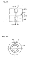
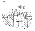
- FIGS. 7 and 8 illustrating the fourth embodiment of the present invention
- sectional views of the pin 22 are presented as in FIG. 2 .
- FIG. 8 presents a more detailed sectional view which includes the angle sensor 21.
- a case 21a A of the angle sensor 21 is housed inside the recessed portion 22a as in FIG. 2 , and is secured to the pin 22 with a screw (not shown) (the screw 26A in FIG. 2 ).
- a flange 218 projects out at an end surface of the case 21aA, and by securing the flange 218 to the end surface 22b of the pin 22 with a bolt 26C, the angle sensor 21 is mounted at the pin 22.
- a protective cover 30B which protects the input shaft 21b from impact from soil and the like, is mounted as an integrated part of the angle sensor 21 at the pin 22 with the bolt 26C.
- One end of the lever 23 is linked to the input shaft 21b projecting out from the end surface 22b of the pin 22, and the other end of the lever 23 is secured to the arm 4 with a bracket 27.
- Reference number 28 indicates a bolt used to mount the bracket 27 at the arm 4.
- An upper end surface 219 of the input shaft 21b in the figure projects out to the side (the upper side in the figure) from the end surface 22b of the pin 22.
- the lever 23 As shown in FIG. 7 , one end of the lever 23 is secured to the arm 4 with a bracket 27, and thus, the lever 23 causes the input shaft 21b of the angle sensor 21 to rotate when the arm 4 is rotated.
- the flange 218 is formed in an arc shape so as to remain outside of the movement range of the lever 23. By forming the flange 218 in an arc shape in this manner, the distance over which the protective cover 30B projects out from the side surface of the boom 3 (h1 in FIG. 8 ) can be minimized. Namely, if the flange 218 is formed in a toroidal shape as a flange 33 in FIG.
- the input shaft 21b must be made to project out further than the flange 33 with the lever 23 provided further to the side (further toward the upper side in the figure) relative to the flange 33.
- the distance h2 > h1
- the projecting distance can be minimized compared to that in the structure shown in FIG. 9 , to prevent falling objects such as soil and rocks from coming into contact with the angle sensor 21 readily.
- the flange 218 projects out so as to enclose the input shaft 21b, the input shaft 21b is protected from falling soil and rocks along the pin end surface 22b (along the direction indicated by the arrow AL in FIG. 8 ) without having to provide the protective cover 30B.
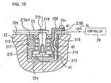
- the protective cover 30B in FIG. 8 .
- the boom pin (the pin 12 in FIG. 1 ) which is not likely to be impacted by soil from the direction of the pin end surface, in particular, does not require the protective cover 30B in this structure.
- FIGS. 11A, 11B and 11C show the case 21aA, with FIG. 11A presenting a front view of the case 21aA, FIG. 11B showing the case 21aA in FIG. 11A viewed from the lower side of the figure and FIG. 11C presenting a sectional view through C-C in FIG. 11A .
- a flange 218 formed as shown in FIGS. 11A ⁇ 11C is provided at the upper end of the case, and the case 21aA is identical to the case 21a shown in FIGS. 4A ⁇ 4C except for the flange 218.
- the grooves 41 extending along the axial direction are formed, and the hole 42 communicating between the upper and lower grooves 41 is formed through the inside of the O-ring groove 40.
- the upper groove 41 in the figures is formed at the lower surface of the flange 218 as well as at a side surface of the case 21aA.
- the portion of the groove 41 formed at the lower surface of the flange 218 extends along the direction of the radius of the case 21aA.
- the harness 216 is provided to extend from the lower groove 41 to the upper groove 41 via the hole 42 as indicated by the 2-point chain line and is drawn out of a flange 218 to be connected to the controller 29, as illustrated in FIG. 10 .
- a case 21aB shown in FIGS. 12A and 12B is a variation of the case 21aA, with FIG. 12A presenting a perspective of the case 21aB and FIG. 12B presenting a sectional view illustrating the case 21aB in detail.
- a housing portion 211a for an oil seal 213, housing portions 211b and 211c for the bearings 212, a housing portion 211d for the resistor 214 and a housing portion 211e for the wiper 215 are individually formed.
- a seal member 34 is provided at the case 21aB.
- FIGS. 13A and 13B respectively present a plan view and a sectional view of the seal member 34.
- the seal member comprises an O-ring portion 34a and the cable passing portion 34b that constitute an integrated component.
- a hole 34c through which a cable 216 passes is formed at the cable passing portion 34b.
- an O-ring groove 40 in which the seal member 34 is placed, and the groove 43 extending along the axial direction in which the cable 216 is placed are formed.
- the cable passing portion 34b of the seal member 34 is set at the groove 43.
- the groove 43 is formed along the axial direction at the side surface of the case 21aB and along the direction of the radius (the horizontal direction in FIG. 12B ) of the case 21aB at the lower surface of the flange 218.
- the cable 216 is provided along the groove 43 from the bottom portion of the case 21aB, passes through the hole 34c at the cable passing portion 34b and is drawn out upward.
- the gap between the cable 216 and the hole 34c is sealed by using a molding material or the like.
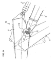
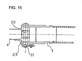
- FIG. 14 is an enlarged view of the vicinity of the pin 22 at the front working apparatus 6 in FIG. 1 and FIG. 15 shows the linking portion in FIG. 14 viewed from direction B3.
- the pin 22 is secured to the boom 3, and the arm 4, which is rotatably linked to the pin 22, is caused to rotate as a hydraulic cylinder 7 expands and contracts. That change in the angle of arm 4 relative to the boom 3 is detected by the angle sensor 21 provided at the pin 22.
- FIG. 16 which shows the angle sensor 21 in FIG. 15 in detail, a recessed portion 22a having a substantially circular cross sectional shape is formed at an end surface of the pin 22 coaxially to the center of the axis of the pin 22 and the angle sensor 21 is provided in the recessed portion 22a as described earlier.
- the angle sensor 21 in FIG. 16 is provided with the case 21aB in FIGS. 12A and 12B .
- the case 21aB is mounted at the pin 22 with the bolt 26C.
- Reference number 30D indicates a protective cover which protects the input shaft 21b from the impact of soil and the like, and the protective cover 30D is mounted at the pin 22 as an integrated part of the angle sensor 21 with the bolt 26C.
- the recessed portion 22a does not need to achieve perfect coaxial alignment with the pin 22 as long as the input shaft 21b of the angle sensor 21 provided inside the recessed portion 22a and the pin 22 achieve coaxial alignment within a specific range, i.e., as long as a sufficient degree of accuracy is assured.
- One end of the lever 23 is linked to the input shaft 21b projecting out from the end surface 22b of the pin 22, and the other end of the lever 23 is secured to the arm 4 with the bracket 27. It is to be noted that the link between the input shaft 21b and the lever 23 is to be detailed later.
- the lever 23 close to the side surfaces of the boom 3 and the arm 4 in this manner, the risk of impact from soil, rocks and the like occurring during operation can be reduced.
- the angle of the arm 4 is changed, i.e., when the arm 4 is rotated by using the pin 22 as the fulcrum, the input shaft 21b of the angle sensor 21 is driven to rotate by the lever 23 secured to the arm 4.
- FIG. 17 is a sectional view illustrating the angle sensor 21 in detail.
- the input shaft 21b is mounted at the case 21aB via bearings 212.
- a hole H substantially perpendicular to the axial direction is formed at the input shaft 21b, and by inserting an end of the lever 23 at the hole H the input shaft 21b and the lever 2 3 are linked.
- the diameter of the hole H is larger than the wire diameter of the lever 23 to allow the lever 23 to slide relative to the hole H along the horizontal direction in the figure.
- Reference number 214 indicates a resistor secured to the input shaft and caused to rotate together with the input shaft, and a wiper 215 is provided at a position facing opposite the resistor 214.
- the sensor unit 21c mentioned earlier is constituted of the resistor 214 and the wiper 215.
- the resistor 214 also rotates, which changes the positions of the resistor 214 and the wiper 215 relative to each other to change the output voltage from the resistor 214.
- This change in the output voltage is communicated to the controller 29 of the hydraulic shovel through a cable 216 connected to the wiper 215, and the change in the angle of the arm 4 relative to the boom 3 is calculated at the controller 29.
- the seal member 34 is provided at the side surface of the case 21aB to prevent entry of water and the like into the bottom portion of the recessed portion 22a.
- the cable 216 passes through the case 21aB and the seal member 34, is drawn out of the sensor through the flange 218 and is connected to the controller 29.
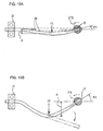
- FIGS. 18A and 18B show the angle sensor 21 and the lever 23 viewed from a side of the boom.
- FIG. 18B shows them in a state in which the protective cover 30D is removed.
- the left end of the lever 23 is secured to the arm 4 with the bracket 27, and when the arm 4 is rotated and its angle changes, the lever 23 causes the input shaft 21b of the angle sensor 21 to rotate.
- the rotating range of the arm 4 over which the arm 4 rotates relative to the boom 3 is limited to a specific angle range by the stroke of the hydraulic cylinder 7 shown in FIG. 14 and, in the example presented in FIG. 18B , the lever 23 interlocking with the arm 4 rotates over the range A1 ⁇ A2 ( ⁇ ⁇ °) indicated by the 2-point chain line.
- the lever 23 is set at A1 when the state of the arm 4 is as indicated by the solid line in FIG. 14 , whereas the lever 23 is set at A2 when the arm 4 has rotated as indicated by the dotted line 4'.
- the lever 23 rotates within the range A1 ⁇ A2, and accordingly, the flange 218 is formed in an arc shape to ensure that the lever 23 and the flange 218 do not interfere with each other, as illustrated in FIG. 18B .
- the input shaft 21b is protected from falling soil, rocks and the like along the end surface of the pin 22 (along the direction indicated by the arrow AL in FIG. 18B ) even without the protective cover 30C. It is not necessary to provide the protective cover 30D especially for the boom pin (pin 12 in FIG. 1 ) which is less likely to impact with soil from the direction of the end surface of the pin 22.
- the embodiment having the lever 23 constituted of an elastic material such as piano wire and slidably inserted at the hole H of the input shaft 21b achieves the following advantages. Namely, the lever 23 undergoes elastic deformation if it is struck by soil or the like to slip out of the hole H, thereby releasing the link between the lever 23 and the input shaft 21b. As a result, the input shaft 21b can not be subjected to an excessive degree of impact.
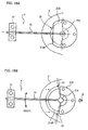
- FIGS. 19A and 19B conceptually illustrate the lever 23 to which loads F1 and F2 along the side surface of the boom 3 applied when the lever 23 comes into contact with soil.
- the load F1 in FIG. 19A is relatively small, whereas FIG. 19B presents an example in which a larger load F2 (F2 > Fl) is applied to the lever 23.
- FIG. 19A indicated by the dotted line is the lever 23 in a normal state in which no impact load is applied to it. It is to be noted that the explanation is given on the assumption that the lever 23 is constituted of a linear piano wire.
- the lever 23 becomes deformed to bend downward due to the load F1 (deformation quantity ⁇ ), and this deformation causes the input shaft 21b to rotate counterclockwise by an angle ⁇ 1.
- the deformation of the lever 23 reduces the length of the lever 23 over which it is inserted at the hole H.
- the deformation quantity ⁇ of the lever 23 increases, causing the input shaft 21b to rotate counterclockwise by a larger angle ⁇ 2 (> ⁇ 1) and, as a result, the length of the lever 23 inserted at the hole H is greatly reduced.
- the level of the load required for the lever 23 to slip out of the hole H at the input shaft 21b is determined in conformance to the elastic coefficient of the piano wire constituting the lever 23, the diameter of the piano wire, the length of the lever 23 over which it is inserted at the hole H and the like, and should be set as appropriate in correspondence to the level of the load tolerated by the angle sensor 21. For instance, by reducing the diameter of the piano wire to allow for easy deformation or by reducing the length over which the lever is inserted at the hole, the lever 23 is allowed to slip out of the hole H even at a small load, to reduce the degree to which the angle sensor 21 is affected.
- FIG. 20A illustrates the lever 23, whose one side is fixed and the other side is a free, to which an external force F applied at the center thereof.
- the deflection ⁇ of the lever 23 occurring in this situation is the largest at a position distanced from the free end by a distance L2.
- the reactive force R applied to the free end is calculated through the following formula (3), and the dimensions of the lever 23 should be set by ensuring that the lever 23 becomes disengaged from the input shaft 21b before the reactive force R exceeds the load limit Sf of the angle sensor 21.
- L2 and A are calculated through formulae (1) and (2).
- d represents the wire diameter of the lever 23
- L represents the full length of the lever 23
- E represents the longitudinal elastic coefficient of the lever 23
- I represents the sectional secondary moment of the lever 23.
- FIG. 20B presents the various dimensions resulting from a deformation of the lever 23 due to the deflection A and FIG. 20C shows the dimensions of the linking portion where the lever 23 and the input shaft 21b are linked.
- the lever 23 is allowed to disengage from the input shaft 21b.
- the wire diameter d of the lever 23 may be determined in correspondence to the full length L of the lever 23 and the deflection ⁇ .
- the cross sectional secondary moment I is calculated.
- the cross sectional secondary moment I thus calculated is then used for substitution in relational 15 expression (8) expressing the relationship between the wire diameter d and I, and then the wire diameter d is calculated through a reverse operation.
- the full length L of the lever 23 may be determined in correspondence to the wire diameter d and the deflection ⁇ of the lever 23.
- FIG. 21A illustrates a normal state in which the lever 70 constituted of an arm link portion 70a, an input shaft securing portion 70b and a shaft portion 70c formed from piano wire or the like is not subjected to any impact load.
- An elongated hole 701 is formed at the arm link portion 70a.
- a connector pin 72 provided at the arm 4 is connected at the elongated hole 701 and the lever 70 and the arm 4 are linked each other.
- the input shaft securing portion 70b is secured to the input shaft 21b with a bolt 71.
- the mechanical strength of the lever 23 may be set so as to cause the lever 23 to break (e.g., to undergo plastic deformation or rupture) if a load equal to or exceeding a specific level is applied to the lever 23 to release the link. While it is necessary to replace the broken lever with a new lever, the lever 23 can be reused if the lever 23 is allowed to slip out of the hole H through elastic deformation, as described earlier. However, by allowing the lever 23 to rupture to release the link, the need to form an end of the lever 23 in such a manner that it can slide relative to the input shaft 21b is eliminated.
- the present invention may be adopted in an angle sensor that detects the boom angle representing the angles of the upper rotating body 1 and the boom 3 of the hydraulic shovel relative to each other or the bucket angle representing the angles of the arm 4 and the bucket 5 relative to each other, an angle sensor that detects the angles of the booms and jibs of various cranes and an angle sensor that detects the angles of articulated arms of an articulated working apparatus.
Abstract
Description
- The disclosures of the following priority applications are herein incorporated by reference:
- Japanese Patent Application No.
11-88797 - Japanese Patent Application No.
11-88798 - Japanese Patent Application No.
11-113794 - The present invention relates to a working apparatus for construction machine and, more specifically, it relates to a working apparatus provided with an angle sensor that measures the relative rotating angles of members rotatably linked to each other such as the boom and the arm of a hydraulic shovel.
- In a construction machine such as a hydraulic shovel, an angle sensor is provided in the working apparatus. In such a working apparatus, the boom and the arm are linked with each other via a pin so as to allow them to rotate relative to each other, and their relative angles are detected by the angle sensor mounted at a side surface of the boom. The angle sensor, which comprises an input shaft, a sensor unit that detects the rotating angle of the input shaft and a case housing the input shaft and the sensor unit. The input shaft is linked or connected to the arm via a lever. When the arm is engaged in rotation relative to the pin, the input shaft at the angle sensor is caused to rotate via the lever which interlocks with the rotation of the arm. The rotating angle of the input shaft is detected by the sensor unit, and the relative angle of the arm is obtained based upon the detected value.
- The angle sensor is mounted at the side surface of the boom so as to project out from the side surface, with one end of the lever linked to the input shaft of the angle sensor and the other end of the lever secured to a side surface of the arm. As a result, problems arise during operation in that the angle sensor and the lever projecting out to a side of the boom come into contact with soil and the like and that the angle sensor and the lever tend to interfere with objects in the vicinity. These problems necessitate a large protective cover to be provided to protect the angle sensor from coming into contact with soil and the like. In addition, when soil or the like comes in contact with the lever, there is a risk of the angle sensor becoming damaged due to the impact to which the input shaft of the angle sensor is subjected via the lever.
- An object of the present invention is to provide a working apparatus for construction machine that prevents the angle sensor provided at the boom or the like from becoming damaged readily by soil and the like.
- In order to achieve the object described above, the working apparatus for construction machine according to the present invention comprises a first member, a second member rotatably linked with the first member via a linking member provided as an integrated part thereof and an angle sensor having an input shaft driven to rotate by the first member and a sensor unit that detects the rotating angle of the input shaft, and a recessed portion is formed at an end surface of the linking member along the axial direction thereof to house, at least, an angle sensor case in its entirety within the recessed portion.
- Thus, the distance by which the angle sensor projects out from the end surface of the linking member along the axial direction thereof is reduced, thereby reducing the risk of falling soil or the like coming into contact with the angle sensor during operation. In particular, by housing the entire angle sensor inside the recessed portion, soil or the like is not allowed to come into contact with the angle sensor readily, and thus, the protective cover can be omitted.
- In addition, a communicating member that links the first member and the input shaft so as to drive the input shaft to rotate by interlocking with the rotation of the first member is provided, (a) a recessed portion is formed at an end surface of the linking member along the axial direction to house the case in the recessed portion and (b) a projected portion projecting out along the axial direction of the input shaft is provided at an end surface of the case so as to enclose the input shaft outside of the movement range of the communicating member. By forming such a projected portion, it is ensured that the input shaft is protected by the projected portion even when soil, rocks and the like come falling down.
- Furthermore, by projecting the projected portion of the case out from the end surface thereof along the axial direction further than the distance over which the input shaft projects out, an improvement is achieved in the protective function of the projected portion in protecting the input shaft. By providing an input shaft protective cover, a further improvement is achieved in the degree of protection provided for the input shaft, and also, by securing the input shaft protective cover and the angle sensor to the linking member with a common fastener, the number of required parts can be reduced.
- By forming a passage for a wiring harness in the angle sensor case, the wiring harness can be drawn out of the recessed portion from the sensor unit with ease.
Alternatively, it is acceptable to provide a seal member that seals the external circumferential surface of the case and the internal circumferential surface of the recessed portion at the external circumferential surface, a groove formed at the external circumferential surface of the case and a passage for the wiring harness formed at the seal member at a position aligned with the position of the groove. - Moreover, by providing a communicating member linking the first member and the input shaft and allowing the link between the first member and the input shaft to become released when an external force equal to or exceeding a specific level is applied to the communicating member, it is possible to ensure that no excessive impact force is applied to the input shaft of the angle sensor, thereby increasing the service life of the angle sensor. For instance, the link may be released by allowing the end of the communicating member slidably inserted in a hole at the input shaft to slip out of the hole or by causing the communicating member to break, when an external force equal to or exceeding the specific level is applied.
-
-
FIG. 1 illustrates a schematic structure of a hydraulic shovel; -
FIG. 2 is a sectional view illustrating the angle sensor in a mounted state in a first embodiment; -
FIG. 3 illustrates theangle sensor 21 inFIG. 2 in further detail; -
FIG. 4A is a front view of thecase 21a; -
FIG. 4B is a bottom view of thecase 21a inFIG. 4A ; -
FIG. 4C is a sectional view through B1-B1 inFIG. 4A ; -
FIG. 5A illustrates a portion of thepin 22 where the angle sensor is provided in a second embodiment, viewed from a side of the boom; -
FIG. 5B is a sectional view through X1-X1 inFIG. 5A ; -
FIG. 6 illustrates a third embodiment; -
FIG. 7 presents a sectional view of thepin 22 provided in a fourth embodiment; -
FIG. 8 illustrates theangle sensor 21 inFIG. 7 in further detail; -
FIG. 9 illustrates a structure achieved by providing aflange 33 over the entire circumference of theinput shaft 21b; -
FIG. 10 illustrates how theharness 216 is mounted; -
FIG. 11A is a front view of the case 21aA; -
FIG. 11B is a bottom view of the case 21aA inFIG. 11A ; -
FIG. 11C is a sectional view through C-C inFIG. 11A ; -
FIG. 12A presents a perspective of the case 21aB which is a variation of the case 21aA; -
FIG. 12B is a sectional view illustrating the case 21aB in detail; -
FIG. 13A is a plan view of theseal member 34; -
FIG. 13B is a sectional view ofFIG. 13A ; -
FIG. 14 is an enlarged view of the area in the vicinity of thepin 22 in thefront operating apparatus 6 inFIG. 1 ; -
FIG. 15 illustrates the linking area inFIG. 14 ,15 viewed from direction B3; -
FIG. 16 illustrates theangle sensor 21 inFIG. 15 in detail; -
FIG. 17 is a sectional view illustrating theangle sensor 21 inFIG. 16 in detail; -
FIG. 18A shows theangle sensor 21 and thelever 23 viewed from a side of the boom; -
FIG. 18B illustrates theangle sensor 21 and thelever 23, with the protective cover 30C inFIG. 18A removed; -
FIG. 19A illustrates thelever 23 in a state in which a load F1 is applied; -
FIG. 19B illustrates thelever 23 in a state in which a load F2 is applied; -
FIG. 20A illustrates thelever 23 in a state in which an external force F is applied; -
FIG. 20B shows the various dimensions of thelever 23 having undergone deformation; -
FIG. 20C shows the dimensions of the linking area where thelever 23 and theinput shaft 21b are linked; -
FIG. 21A presents another example in which the link can be released, illustrating a state in which no impact load is applied to thelever 70; and -
FIG. 21B illustrates a state in which the load F2 is applied in the other example of link which can be released. - The following is an explanation of the preferred embodiments of the present invention, given in reference to the drawings.
- In
FIG. 1 illustrating a schematic structure of a hydraulic shovel, an upperrotating body 2 is provided at alower traveling body 1 via a rotating mechanism. A front workingapparatus 6 comprising aboom 3, anarm 4 and abucket 5 is provided at the upperrotating body 2. Theboom 3, thearm 4 and thebucket 5 are rotatably linked so as to allow them to rotate relative to thepins -
FIG. 2 shows an angle sensor in a mounted state at the operating apparatus according to the present invention in a sectional view of the essential portion of the operating apparatus through line I-I inFIG. 1 . As explained earlier, theboom 3 and thearm 4 are rotatably connected with each other via thefront pin 22. Thepin 22 is secured to theboom 3 with abolt 24 and thearm 4 is rotatably linked to thepin 22. At an end surface of thepin 22, a recessedportion 22a having a circular cross-sectional shape is formed coaxially to the center of the axis of thepin 22 to house anangle sensor 21. Theangle sensor 21 comprises acase 21a, aninput shaft 21b and asensor unit 21c. Thecase 21a of theangle sensor 21 is housed inside the recessedportion 22a so as to allow theinput shaft 21b to project out from the end surface of thepin 22 and is secured to thepin 22 through a screw 26a. - While it is desirable to form the recessed
portion 22a coaxially to thepin 22 in order to assure a high degree of detection accuracy, the recessedportion 22a does not need to be perfectly coaxial with thepin 22 as long as a sufficient degree of accuracy is assured with regard to the coaxial alignment of theinput shaft 21b of theangle sensor 21 housed in the recessedportion 22a and thepin 22. - One end of a
lever 23 is linked to theinput shaft 21b and the other end of thelever 23 is secured to thearm 4 through a bolt 25. Thus, when the angle of thearm 4 changes, i.e., when thearm 4 is rotated by using thepin 22 as the fulcrum, theinput shaft 21b of theangle sensor 21 is driven to rotate by thelever 23 secured to thearm 4. -
FIG. 3 is a sectional view illustrating theangle sensor 21 in detail. Theinput shaft 21b is mounted at thecase 21a viabearings 212. Above thebearings 212 in the figure, aseal 213 which prevents water, oil, mud or the like from entering the case is provided.Reference number 214 is a resistor secured to theinput shaft 21b, which rotates together with theinput shaft 21b, and awiper 215 is provided at a position facing opposite theresistor 214. Thesensor unit 21c (seeFIG. 2 ) mentioned earlier is constituted of theresistor 214 and thewiper 215. When theinput shaft 21b is driven to rotate by thelever 23, theresistor 214 engages in rotation, causing the positions of theresistor 214 and thewiper 215 relative to each other to change, which results in a change in the output voltage. This change occurring in the output voltage is communicated to acontroller 29 of the hydraulic shovel by aharness 216 connected to thewiper 215, and a change in the angle of thearm 4 relative to theboom 3 is calculated at thecontroller 29. Aseal member 217 such as an O-ring is provided at a side surface of thecase 21a to prevent water and the like from entering the bottom portion of the recessedportion 22a. - The
harness 216 is drawn out of the recessedportion 22a via a passage (grooves 41 and ahole 42 to be detailed later) extending from the bottom of thecase 21a through thecase 21a and is connected to thecontroller 29.FIGS. 4A ~ 4C illustrate thecase 21a, withFIG. 4A presenting a front view of thecase 21a,FIG. 4B showing thecase 21a inFIG. 4A viewed from the lower side of the figure andFIG. 4C presenting a sectional view through B1-B1 inFIG. 4B . Inside thecase 21a formed in a roughly cylindrical shape, ahousing portion 211a for theseal 213,housing portions bearings 212, ahousing portion 211d for theresistor 214 and ahousing portion 211e for thewiper 215 are individually formed. An O-ring groove 40 is formed as a recessed passage at the external circumference of thecase 21a. Above and below the O-ring groove 40, thegrooves 41 running along the axial direction are formed, and thehole 42 communicating between the upper andlower grooves 41 is formed through the inside of the O-ring groove 40. Theharness 216 is threaded from thelower groove 41 to theupper groove 41 via thehole 42, as indicated by the 2-point chain line inFIG. 4C , to be connected to thecontroller 29 as shown inFIG. 3 . - As described above, in this embodiment having the
case 21a of theangle sensor 21 provided inside the recessedportion 22a formed at the end surface of thepin 22 along the axial direction, the distance over which theangle sensor 21 projects out from the boom side surface is reduced, thereby reducing the risk of soil, rocks and the like coming into contact with theangle sensor 21 during operation. -
FIGS. 5A and 5B illustrate the second embodiment of the present invention, withFIG. 5A showing thepin 22 over the area where the angle sensor is provided viewed from a side of the boom andFIG. 5B presenting a sectional view through X1-X1 inFIG. 5A . In the embodiments, aprotective cover 30A is provided at a side of theinput shaft 21b. Theprotective cover 30A, which is mounted at an end surface of thepin 22 with abolt 26B, achieves a shape which allows it to cover thecase 21a and theinput shaft 21b of theangle sensor 21 in their entirety viewed from a side of theboom 3. Theangle sensor 21 is protected by theprotective cover 30A in this manner, so that soil and the like are prevented from coming into contact with theangle sensor 21 from a side of theboom 3. - Since the
entire case 21a is housed inside the recessedportion 22a and theinput shaft 21b alone is projected out to the side (the upper side in the figure) from thepin end surface 22b in this embodiment, too, the distance h over which theprotective cover 30A projects out can be reduced compared to the prior art. - In
FIG. 6 , illustrating the third embodiment of the present invention, theentire angle sensor 21 including 15 theinput shaft 21b is housed inside the recessedportion 22a of thepin 22. By housing theentire angle sensor 21 inside the recessedportion 22a in this manner, only thelever 23 is projected out of a side of the boom, thereby making it possible to dispense with a protective cover for protecting theangle sensor 21. - In
FIGS. 7 and8 illustrating the fourth embodiment of the present invention, sectional views of thepin 22 are presented as inFIG. 2 .FIG. 8 presents a more detailed sectional view which includes theangle sensor 21. Acase 21a A of theangle sensor 21 is housed inside the recessedportion 22a as inFIG. 2 , and is secured to thepin 22 with a screw (not shown) (thescrew 26A inFIG. 2 ). - A
flange 218 projects out at an end surface of the case 21aA, and by securing theflange 218 to theend surface 22b of thepin 22 with a bolt 26C, theangle sensor 21 is mounted at thepin 22. Aprotective cover 30B, which protects theinput shaft 21b from impact from soil and the like, is mounted as an integrated part of theangle sensor 21 at thepin 22 with the bolt 26C. - One end of the
lever 23 is linked to theinput shaft 21b projecting out from theend surface 22b of thepin 22, and the other end of thelever 23 is secured to thearm 4 with abracket 27.Reference number 28 indicates a bolt used to mount thebracket 27 at thearm 4. Anupper end surface 219 of theinput shaft 21b in the figure projects out to the side (the upper side in the figure) from theend surface 22b of thepin 22. - As shown in
FIG. 7 , one end of thelever 23 is secured to thearm 4 with abracket 27, and thus, thelever 23 causes theinput shaft 21b of theangle sensor 21 to rotate when thearm 4 is rotated. Theflange 218 is formed in an arc shape so as to remain outside of the movement range of thelever 23. By forming theflange 218 in an arc shape in this manner, the distance over which theprotective cover 30B projects out from the side surface of the boom 3 (h1 inFIG. 8 ) can be minimized. Namely, if theflange 218 is formed in a toroidal shape as aflange 33 inFIG. 9 is, theinput shaft 21b must be made to project out further than theflange 33 with thelever 23 provided further to the side (further toward the upper side in the figure) relative to theflange 33. As a result, there is a problem in that the distance h2 (> h1) over which the protective cover 30C projects out from the side surface of theboom 3 becomes large. However, in the embodiment described above, the projecting distance can be minimized compared to that in the structure shown inFIG. 9 , to prevent falling objects such as soil and rocks from coming into contact with theangle sensor 21 readily. - In addition, since the
flange 218 projects out so as to enclose theinput shaft 21b, theinput shaft 21b is protected from falling soil and rocks along thepin end surface 22b (along the direction indicated by the arrow AL inFIG. 8 ) without having to provide theprotective cover 30B. Thus, by setting theend surface 219 of theinput shaft 21b further toward the pin relative to an end asurface 220 of theflange 218 as illustrated inFIG. 10 , it becomes possible to dispense with theprotective cover 30B inFIG. 8 . The boom pin (thepin 12 inFIG. 1 ) which is not likely to be impacted by soil from the direction of the pin end surface, in particular, does not require theprotective cover 30B in this structure. - Next, a specific method for mounting the
harness 216 is explained. As illustrated inFIG. 10 , theharness 216 is drawn out of the recessedportion 22a via a passage (grooves 41 and ahole 42 to be detailed later) extending from the bottom portion of the case 21aA through the case 21aA and is connected to thecontroller 29.FIGS. 11A, 11B and 11C show the case 21aA, withFIG. 11A presenting a front view of the case 21aA,FIG. 11B showing the case 21aA inFIG. 11A viewed from the lower side of the figure andFIG. 11C presenting a sectional view through C-C inFIG. 11A . Aflange 218 formed as shown inFIGS. 11A ~ 11C is provided at the upper end of the case, and the case 21aA is identical to thecase 21a shown inFIGS. 4A ~ 4C except for theflange 218. - At positions above and below the O-
ring groove 40, thegrooves 41 extending along the axial direction are formed, and thehole 42 communicating between the upper andlower grooves 41 is formed through the inside of the O-ring groove 40. It is to be noted that theupper groove 41 in the figures is formed at the lower surface of theflange 218 as well as at a side surface of the case 21aA.
The portion of thegroove 41 formed at the lower surface of theflange 218 extends along the direction of the radius of the case 21aA. Theharness 216 is provided to extend from thelower groove 41 to theupper groove 41 via thehole 42 as indicated by the 2-point chain line and is drawn out of aflange 218 to be connected to thecontroller 29, as illustrated inFIG. 10 . - A case 21aB shown in
FIGS. 12A and 12B is a variation of the case 21aA, withFIG. 12A presenting a perspective of the case 21aB andFIG. 12B presenting a sectional view illustrating the case 21aB in detail. Inside the case 21aB, which is formed in a roughly cylindrical shape as is the case 21aA, ahousing portion 211a for anoil seal 213,housing portions bearings 212, ahousing portion 211d for theresistor 214 and ahousing portion 211e for thewiper 215 are individually formed. As illustrated inFIG. 12A , aseal member 34 is provided at the case 21aB. -
FIGS. 13A and 13B respectively present a plan view and a sectional view of theseal member 34. The seal member comprises an O-ring portion 34a and thecable passing portion 34b that constitute an integrated component. Ahole 34c through which acable 216 passes is formed at thecable passing portion 34b. - At the external circumferential surface of the case 21aB, shown in
FIGS. 12A and 12B , an O-ring groove 40, in which theseal member 34 is placed, and thegroove 43 extending along the axial direction in which thecable 216 is placed are formed. When mounting theseal member 34 in thegroove 40, thecable passing portion 34b of theseal member 34 is set at thegroove 43. Thegroove 43 is formed along the axial direction at the side surface of the case 21aB and along the direction of the radius (the horizontal direction inFIG. 12B ) of the case 21aB at the lower surface of theflange 218. Thecable 216 is provided along thegroove 43 from the bottom portion of the case 21aB, passes through thehole 34c at thecable passing portion 34b and is drawn out upward. The gap between thecable 216 and thehole 34c is sealed by using a molding material or the like. - Next, the fifth embodiment is explained in reference to
FIGS. 14 ~ 20C . The fifth embodiment is characterized by the connection between thelever 23 and theinput shaft 21b.FIG. 14 is an enlarged view of the vicinity of thepin 22 at the front workingapparatus 6 inFIG. 1 andFIG. 15 shows the linking portion inFIG. 14 viewed from direction B3. Thepin 22 is secured to theboom 3, and thearm 4, which is rotatably linked to thepin 22, is caused to rotate as ahydraulic cylinder 7 expands and contracts. That change in the angle ofarm 4 relative to theboom 3 is detected by theangle sensor 21 provided at thepin 22. InFIG. 16 , which shows theangle sensor 21 inFIG. 15 in detail, a recessedportion 22a having a substantially circular cross sectional shape is formed at an end surface of thepin 22 coaxially to the center of the axis of thepin 22 and theangle sensor 21 is provided in the recessedportion 22a as described earlier. - The
angle sensor 21 inFIG. 16 is provided with the case 21aB inFIGS. 12A and 12B . The case 21aB is mounted at thepin 22 with the bolt 26C.Reference number 30D indicates a protective cover which protects theinput shaft 21b from the impact of soil and the like, and theprotective cover 30D is mounted at thepin 22 as an integrated part of theangle sensor 21 with the bolt 26C. As explained earlier, while it is desirable to form the recessedportion 22a coaxially to thepin 22, in order to achieve a higher degree of detection accuracy, the recessedportion 22a does not need to achieve perfect coaxial alignment with thepin 22 as long as theinput shaft 21b of theangle sensor 21 provided inside the recessedportion 22a and thepin 22 achieve coaxial alignment within a specific range, i.e., as long as a sufficient degree of accuracy is assured. One end of thelever 23 is linked to theinput shaft 21b projecting out from theend surface 22b of thepin 22, and the other end of thelever 23 is secured to thearm 4 with thebracket 27. It is to be noted that the link between theinput shaft 21b and thelever 23 is to be detailed later. Thelever 23, which is constituted of an elastic material such as a piano wire (the following explanation is given on the assumption that thelever 23 is constituted of a piano wire) is formed to extend along a path close to the side surfaces of theboom 3 and thearm 4, as shown inFIG. 16 . By providing thelever 23 close to the side surfaces of theboom 3 and thearm 4 in this manner, the risk of impact from soil, rocks and the like occurring during operation can be reduced. When the angle of thearm 4 is changed, i.e., when thearm 4 is rotated by using thepin 22 as the fulcrum, theinput shaft 21b of theangle sensor 21 is driven to rotate by thelever 23 secured to thearm 4. -
FIG. 17 is a sectional view illustrating theangle sensor 21 in detail. Theinput shaft 21b is mounted at the case 21aB viabearings 212. A hole H substantially perpendicular to the axial direction is formed at theinput shaft 21b, and by inserting an end of thelever 23 at the hole H theinput shaft 21b and thelever 2 3 are linked. The diameter of the hole H is larger than the wire diameter of thelever 23 to allow thelever 23 to slide relative to the hole H along the horizontal direction in the figure. - Above the
bearings 212 in the figure, oil seals 213 for preventing entry of water, oil, mud and the like into the case are provided.Reference number 214 indicates a resistor secured to the input shaft and caused to rotate together with the input shaft, and awiper 215 is provided at a position facing opposite theresistor 214. Thesensor unit 21c mentioned earlier is constituted of theresistor 214 and thewiper 215. When theinput shaft 21b is driven to rotate by thelever 23, theresistor 214 also rotates, which changes the positions of theresistor 214 and thewiper 215 relative to each other to change the output voltage from theresistor 214. This change in the output voltage is communicated to thecontroller 29 of the hydraulic shovel through acable 216 connected to thewiper 215, and the change in the angle of thearm 4 relative to theboom 3 is calculated at thecontroller 29. - The
seal member 34, mentioned earlier (seeFIGS. 13A and 13B ), is provided at the side surface of the case 21aB to prevent entry of water and the like into the bottom portion of the recessedportion 22a. Thecable 216 passes through the case 21aB and theseal member 34, is drawn out of the sensor through theflange 218 and is connected to thecontroller 29. -
FIGS. 18A and 18B show theangle sensor 21 and thelever 23 viewed from a side of the boom.FIG. 18B shows them in a state in which theprotective cover 30D is removed. The left end of thelever 23 is secured to thearm 4 with thebracket 27, and when thearm 4 is rotated and its angle changes, thelever 23 causes theinput shaft 21b of theangle sensor 21 to rotate. The rotating range of thearm 4 over which thearm 4 rotates relative to theboom 3 is limited to a specific angle range by the stroke of thehydraulic cylinder 7 shown inFIG. 14 and, in the example presented inFIG. 18B , thelever 23 interlocking with thearm 4 rotates over the range A1 ~ A2 (± α°) indicated by the 2-point chain line. It is to be noted that thelever 23 is set at A1 when the state of thearm 4 is as indicated by the solid line inFIG. 14 , whereas thelever 23 is set at A2 when thearm 4 has rotated as indicated by the dotted line 4'. As described above, thelever 23 rotates within the range A1 ~ A2, and accordingly, theflange 218 is formed in an arc shape to ensure that thelever 23 and theflange 218 do not interfere with each other, as illustrated inFIG. 18B . By projecting out the arc-shapedflange 218 so as to enclose theinput shaft 21b in this manner, theinput shaft 21b is protected from falling soil, rocks and the like along the end surface of the pin 22 (along the direction indicated by the arrow AL inFIG. 18B ) even without the protective cover 30C. It is not necessary to provide theprotective cover 30D especially for the boom pin (pin 12 inFIG. 1 ) which is less likely to impact with soil from the direction of the end surface of thepin 22. - The embodiment having the
lever 23 constituted of an elastic material such as piano wire and slidably inserted at the hole H of theinput shaft 21b achieves the following advantages. Namely, thelever 23 undergoes elastic deformation if it is struck by soil or the like to slip out of the hole H, thereby releasing the link between thelever 23 and theinput shaft 21b. As a result, theinput shaft 21b can not be subjected to an excessive degree of impact. -
FIGS. 19A and 19B conceptually illustrate thelever 23 to which loads F1 and F2 along the side surface of theboom 3 applied when thelever 23 comes into contact with soil. The load F1 inFIG. 19A is relatively small, whereasFIG. 19B presents an example in which a larger load F2 (F2 > Fl) is applied to thelever 23. InFIG. 19A , indicated by the dotted line is thelever 23 in a normal state in which no impact load is applied to it. It is to be noted that the explanation is given on the assumption that thelever 23 is constituted of a linear piano wire. - In the example presented in
FIG. 19A , thelever 23 becomes deformed to bend downward due to the load F1 (deformation quantity Δ), and this deformation causes theinput shaft 21b to rotate counterclockwise by an angle θ1. In addition, the deformation of thelever 23 reduces the length of thelever 23 over which it is inserted at the hole H. In the example presented inFIG. 19B , with the larger load F2 applied to thelever 23, the deformation quantity Δ of thelever 23 increases, causing theinput shaft 21b to rotate counterclockwise by a larger angle θ2 (>θ1) and, as a result, the length of thelever 23 inserted at the hole H is greatly reduced. If a load even larger than F2 is applied to thelever 23, i.e., if (impact load) > F2, the deformation quantity Δ of thelever 23 and the rotating angle of theinput shaft 21b further increase, to result in thelever 23 slipping out of the hole H as indicated by the two-point chain line, thereby releasing the link between thelever 2 3 and theinput shaft 21b. - If a strong lever constituted of a steel plate, for instance, as in the prior art is secured to the
input shaft 21b, the link between theinput shaft 21b and the lever is not released even when an excessive load is applied to the lever, resulting in a great impact force being applied to theinput shaft 21b. This presents a risk of thebearings 212 supporting theinput shaft 21b and thesensor unit 21c becoming damaged when the lever comes in contact with rocks and the like. However, in this embodiment, in which the link between thelever 23 and theinput shaft 21b is released if an excessive load is applied to thelever 23 as described above, no excessively large impact force is applied to theinput shaft 21b and an increase in the service life of theangle sensor 21 is achieved. - The level of the load required for the
lever 23 to slip out of the hole H at theinput shaft 21b is determined in conformance to the elastic coefficient of the piano wire constituting thelever 23, the diameter of the piano wire, the length of thelever 23 over which it is inserted at the hole H and the like, and should be set as appropriate in correspondence to the level of the load tolerated by theangle sensor 21. For instance, by reducing the diameter of the piano wire to allow for easy deformation or by reducing the length over which the lever is inserted at the hole, thelever 23 is allowed to slip out of the hole H even at a small load, to reduce the degree to which theangle sensor 21 is affected. - An example of the method for setting the dimensions of the
lever 23 is now explained in reference toFIGS. 20A ~ 20D. FIG. 20A illustrates thelever 23, whose one side is fixed and the other side is a free, to which an external force F applied at the center thereof. The deflection Δ of thelever 23 occurring in this situation is the largest at a position distanced from the free end by a distance L2. The reactive force R applied to the free end is calculated through the following formula (3), and the dimensions of thelever 23 should be set by ensuring that thelever 23 becomes disengaged from theinput shaft 21b before the reactive force R exceeds the load limit Sf of theangle sensor 21. In addition, L2 and A are calculated through formulae (1) and (2).


- It is to be noted that d represents the wire diameter of the
lever 23, L represents the full length of thelever 23, E represents the longitudinal elastic coefficient of thelever 23 and I represents the sectional secondary moment of thelever 23. -
FIG. 20B presents the various dimensions resulting from a deformation of thelever 23 due to the deflection A andFIG. 20C shows the dimensions of the linking portion where thelever 23 and theinput shaft 21b are linked. The individual dimensions L3 ~ L5 inFIG. 20B are calculated through the following formulae (4) ~ (6);


- Namely, by ensuring that (L5 + a1) is larger than "a" when the deflection A has occurred, the
lever 23 is allowed to disengage from theinput shaft 21b. For instance, the wire diameter d of thelever 23 may be determined in correspondence to the full length L of thelever 23 and the deflection Δ. By setting the full length L and the deflection Δ of thelever 23 at specific values and using those values for L and Δ in the following formula (7) which is obtained from formula (2), for substitution, the cross sectional secondary moment I is calculated. The cross sectional secondary moment I thus calculated is then used for substitution in relational 15 expression (8) expressing the relationship between the wire diameter d and I, and then the wire diameter d is calculated through a reverse operation. Alternatively, the full length L of thelever 23 may be determined in correspondence to the wire diameter d and the deflection Δ of thelever 23.

- While an explanation is given in reference to the embodiment above on an example in which the link between the
lever 23 and theinput shaft 21b is released, the link between thearm 4 and alever 70 may be released as illustrated inFIGS. 21A and 21B instead.FIG. 21A illustrates a normal state in which thelever 70 constituted of anarm link portion 70a, an inputshaft securing portion 70b and ashaft portion 70c formed from piano wire or the like is not subjected to any impact load. Anelongated hole 701 is formed at thearm link portion 70a. Aconnector pin 72 provided at thearm 4 is connected at theelongated hole 701 and thelever 70 and thearm 4 are linked each other. The inputshaft securing portion 70b is secured to theinput shaft 21b with abolt 71. - If the load F2 (the force working along the side surface of the boom 3) is applied to the
shaft portion 70c of thelever 70 as shown inFIG. 21B , theshaft portion 70c becomes deformed to bend out downward to cause theinput shaft 21b to rotate counterclockwise by an angle θ4 and to tilt thearm link portion 70a by an angle θ3 relative to the horizontal direction. While theelongated hole 701 of thearm link portion 70a is still connected with thepin 22 in this state, the connection of theelongated hole 701 and thepin 72, i.e., the link between thelever 70 and thearm 4, is released, as indicated by the two-point chain line inFIGS. 21B if a load any larger than F2 is applied. - Furthermore, the mechanical strength of the
lever 23 may be set so as to cause thelever 23 to break (e.g., to undergo plastic deformation or rupture) if a load equal to or exceeding a specific level is applied to thelever 23 to release the link. While it is necessary to replace the broken lever with a new lever, thelever 23 can be reused if thelever 23 is allowed to slip out of the hole H through elastic deformation, as described earlier. However, by allowing thelever 23 to rupture to release the link, the need to form an end of thelever 23 in such a manner that it can slide relative to theinput shaft 21b is eliminated. - While an explanation is given above in reference to the embodiments on an example in which the present invention is adopted in an angle sensor that detects the angles of the
boom 3 and thearm 4 relative to each other, the present invention may be adopted in an angle sensor that detects the boom angle representing the angles of the upperrotating body 1 and theboom 3 of the hydraulic shovel relative to each other or the bucket angle representing the angles of thearm 4 and thebucket 5 relative to each other, an angle sensor that detects the angles of the booms and jibs of various cranes and an angle sensor that detects the angles of articulated arms of an articulated working apparatus.
Claims (6)
- A working apparatus for construction machine comprising:a first member;a second member rotatably linked with said first member via a linking member provided as an integrated part thereof;an angle sensor internally provided with a sensor unit for detecting a rotating angle of an input shaft in a case secured to said linking member; anda communicating member that links said first member to said input shaft so as to drive said input shaft to rotate by interlocking with the rotation of said first member, wherein;(a) a recessed portion is formed at an end surface of said linking member along an axial direction thereof to house said case within said recessed portion; and(b) a projected portion projecting out along an axial direction of said input shaft is provided at an end surface of said case so as to enclose said input shaft outside a movement range of said communicating member.
- A working apparatus according to claim 1, wherein;
a distance over which said projected portion projects out from the end surface of said linking member along the axial direction thereof is set larger than the distance over which the end surface of said input shaft projects out from the end of the linking member along the axial direction of said input shaft. - A working apparatus according to claim 1 or 2, wherein;
an input shaft protective cover that covers said input shaft for protection is provided, and
said input shaft protective cover and said case are secured to said linking member with a common fastener. - A working apparatus according to any one of claims 1 to 3, wherein;
a passage for allowing a wiring harness extending from said sensor unit to be drawn out of said recessed portion is formed at said case. - A working apparatus according to any one of claims 1 to 3, wherein;
a seal member that seals an external circumferential surface of said case and an internal circumferential surface of said recessed portion is provided at said external circumferential, surface; and
a groove that allows a wiring harness extending from said sensor unit to be drawn out of said recessed portion is formed at said external circumferential surface and a passage for said wiring harness is formed at said seal member at a position aligned with said groove. - A working apparatus according to any one of claims 1 to 5, wherein;
said first member is an arm and said second member is a boom.
Applications Claiming Priority (4)
| Application Number | Priority Date | Filing Date | Title |
|---|---|---|---|
| JP08879799A JP3517150B2 (en) | 1999-03-30 | 1999-03-30 | Construction equipment working equipment |
| JP08879899A JP3859106B2 (en) | 1999-03-30 | 1999-03-30 | Construction equipment working equipment |
| JP11379499A JP3550508B2 (en) | 1999-04-21 | 1999-04-21 | Working equipment for construction machinery |
| EP00912954A EP1092809B1 (en) | 1999-03-30 | 2000-03-30 | Working device of construction machinery |
Related Parent Applications (2)
| Application Number | Title | Priority Date | Filing Date |
|---|---|---|---|
| EP00912954A Division EP1092809B1 (en) | 1999-03-30 | 2000-03-30 | Working device of construction machinery |
| EP00912954.5 Division | 2000-03-30 |
Publications (3)
| Publication Number | Publication Date |
|---|---|
| EP1930507A2 true EP1930507A2 (en) | 2008-06-11 |
| EP1930507A3 EP1930507A3 (en) | 2008-08-20 |
| EP1930507B1 EP1930507B1 (en) | 2010-02-24 |
Family
ID=27305913
Family Applications (3)
| Application Number | Title | Priority Date | Filing Date |
|---|---|---|---|
| EP08153823A Withdrawn EP1930508A3 (en) | 1999-03-30 | 2000-03-30 | Working apparatus for construction machine |
| EP08153814A Expired - Lifetime EP1930507B1 (en) | 1999-03-30 | 2000-03-30 | Working apparatus for construction machine |
| EP00912954A Expired - Lifetime EP1092809B1 (en) | 1999-03-30 | 2000-03-30 | Working device of construction machinery |
Family Applications Before (1)
| Application Number | Title | Priority Date | Filing Date |
|---|---|---|---|
| EP08153823A Withdrawn EP1930508A3 (en) | 1999-03-30 | 2000-03-30 | Working apparatus for construction machine |
Family Applications After (1)
| Application Number | Title | Priority Date | Filing Date |
|---|---|---|---|
| EP00912954A Expired - Lifetime EP1092809B1 (en) | 1999-03-30 | 2000-03-30 | Working device of construction machinery |
Country Status (6)
| Country | Link |
|---|---|
| US (1) | US6564480B1 (en) |
| EP (3) | EP1930508A3 (en) |
| KR (1) | KR100399727B1 (en) |
| CN (1) | CN100469979C (en) |
| DE (2) | DE60041169D1 (en) |
| WO (1) | WO2000058571A1 (en) |
Cited By (1)
| Publication number | Priority date | Publication date | Assignee | Title |
|---|---|---|---|---|
| WO2010116203A1 (en) * | 2009-04-06 | 2010-10-14 | Aktiebolaget Skf | Detection system, joint system provided with such a detection system and automotive vehicle equipped with such a joint system |
Families Citing this family (11)
| Publication number | Priority date | Publication date | Assignee | Title |
|---|---|---|---|---|
| FR2902699B1 (en) | 2006-06-26 | 2010-10-22 | Skf Ab | SUSPENSION STOP DEVICE AND FORCE LEG. |
| FR2904671B1 (en) * | 2006-08-02 | 2009-03-13 | Skf Ab | INSTRUMENT JOINT SYSTEM. |
| FR2906587B1 (en) | 2006-10-03 | 2009-07-10 | Skf Ab | TENDERING ROLLER DEVICE. |
| FR2913081B1 (en) | 2007-02-27 | 2009-05-15 | Skf Ab | DEBRAYABLE PULLEY DEVICE |
| FR2915280B1 (en) * | 2007-04-19 | 2009-07-10 | Skf Ab | INSTRUMENT JOINT SYSTEM. |
| WO2010038102A1 (en) * | 2008-10-03 | 2010-04-08 | Aktiebolaget Skf | Pin for a joint between two pivoting parts, joint system provided with such a pin, automotive vehicle equipped with such a joint system and process for manufacturing such a pin |
| US8428832B2 (en) * | 2008-12-23 | 2013-04-23 | Caterpillar Inc. | Method and apparatus for calculating payload weight |
| US8515627B2 (en) * | 2008-12-23 | 2013-08-20 | Caterpillar Inc. | Method and apparatus for calculating payload weight |
| KR101751831B1 (en) * | 2011-05-31 | 2017-07-11 | 대우조선해양 주식회사 | Riser having angle sensor |
| US8726529B2 (en) | 2012-03-27 | 2014-05-20 | Cnh Industrial America Llc | Rotary sensor assembly |
| ITMI20130495A1 (en) * | 2013-03-29 | 2014-09-30 | Atlas Copco Blm Srl | ELECTRONIC CONTROL AND CONTROL DEVICE FOR SENSORS |
Citations (4)
| Publication number | Priority date | Publication date | Assignee | Title |
|---|---|---|---|---|
| JPH08260525A (en) | 1995-03-17 | 1996-10-08 | Mitsubishi Agricult Mach Co Ltd | Hydraulic shovel |
| JPH1188798A (en) | 1997-09-03 | 1999-03-30 | Toshiba Corp | Dynamic image display device, its method and storage medium |
| JPH1188797A (en) | 1997-09-12 | 1999-03-30 | Toshiba Corp | Agc circuit |
| JPH11113794A (en) | 1997-10-15 | 1999-04-27 | Mitsubishi Electric Corp | Hand drier |
Family Cites Families (6)
| Publication number | Priority date | Publication date | Assignee | Title |
|---|---|---|---|---|
| JPS5681504A (en) * | 1979-12-08 | 1981-07-03 | Sankyo Co Ltd | Preventive for damping-off of rice plant |
| JPH03106406U (en) * | 1990-02-13 | 1991-11-01 | ||
| JP3106406B2 (en) | 1991-01-31 | 2000-11-06 | 雪印乳業株式会社 | Gel modification method |
| US5657544A (en) * | 1995-09-26 | 1997-08-19 | Ntn Corporation | Device for detecting the angle of rotation |
| JP4023645B2 (en) * | 1998-12-08 | 2007-12-19 | 株式会社小松製作所 | Hydraulic excavator offset angle sensor protective mounting structure |
| JP4166925B2 (en) * | 2000-05-19 | 2008-10-15 | 日立建機株式会社 | Two-member connecting device |
-
2000
- 2000-03-30 EP EP08153823A patent/EP1930508A3/en not_active Withdrawn
- 2000-03-30 EP EP08153814A patent/EP1930507B1/en not_active Expired - Lifetime
- 2000-03-30 WO PCT/JP2000/001997 patent/WO2000058571A1/en active IP Right Grant
- 2000-03-30 CN CNB008004722A patent/CN100469979C/en not_active Expired - Fee Related
- 2000-03-30 EP EP00912954A patent/EP1092809B1/en not_active Expired - Lifetime
- 2000-03-30 DE DE60041169T patent/DE60041169D1/en not_active Expired - Lifetime
- 2000-03-30 KR KR10-2000-7013492A patent/KR100399727B1/en not_active IP Right Cessation
- 2000-03-30 DE DE60043911T patent/DE60043911D1/en not_active Expired - Lifetime
- 2000-11-28 US US09/722,566 patent/US6564480B1/en not_active Expired - Lifetime
Patent Citations (4)
| Publication number | Priority date | Publication date | Assignee | Title |
|---|---|---|---|---|
| JPH08260525A (en) | 1995-03-17 | 1996-10-08 | Mitsubishi Agricult Mach Co Ltd | Hydraulic shovel |
| JPH1188798A (en) | 1997-09-03 | 1999-03-30 | Toshiba Corp | Dynamic image display device, its method and storage medium |
| JPH1188797A (en) | 1997-09-12 | 1999-03-30 | Toshiba Corp | Agc circuit |
| JPH11113794A (en) | 1997-10-15 | 1999-04-27 | Mitsubishi Electric Corp | Hand drier |
Cited By (2)
| Publication number | Priority date | Publication date | Assignee | Title |
|---|---|---|---|---|
| WO2010116203A1 (en) * | 2009-04-06 | 2010-10-14 | Aktiebolaget Skf | Detection system, joint system provided with such a detection system and automotive vehicle equipped with such a joint system |
| US9187876B2 (en) | 2009-04-06 | 2015-11-17 | Aktiebolaget Skf | Detection system, joint system provided with such a detection system and automotive vehicle equipped with such a joint system |
Also Published As
| Publication number | Publication date |
|---|---|
| EP1930507A3 (en) | 2008-08-20 |
| WO2000058571A1 (en) | 2000-10-05 |
| EP1092809A4 (en) | 2003-01-15 |
| EP1092809A1 (en) | 2001-04-18 |
| DE60041169D1 (en) | 2009-02-05 |
| KR20010071350A (en) | 2001-07-28 |
| EP1930508A3 (en) | 2008-09-03 |
| CN1297504A (en) | 2001-05-30 |
| CN100469979C (en) | 2009-03-18 |
| EP1930508A2 (en) | 2008-06-11 |
| KR100399727B1 (en) | 2003-09-26 |
| DE60043911D1 (en) | 2010-04-08 |
| EP1092809B1 (en) | 2008-12-24 |
| EP1930507B1 (en) | 2010-02-24 |
| US6564480B1 (en) | 2003-05-20 |
Similar Documents
| Publication | Publication Date | Title |
|---|---|---|
| EP1930507B1 (en) | Working apparatus for construction machine | |
| AU2016223359B2 (en) | Device for attaching a wear or protection element to a shovel of a soil-shifting machine and corresponding attachment method and wear or protection system | |
| CA2801528C (en) | Wear assembly for machinery | |
| CN107304568B (en) | Construction machine | |
| US9632200B2 (en) | Wear member retention system for an implement | |
| WO2016033428A1 (en) | Hammerless pin assembly | |
| CA2936434C (en) | Wear member retention system for an implement | |
| US20040164042A1 (en) | Jib load limiting device | |
| JP3550508B2 (en) | Working equipment for construction machinery | |
| CN101130997A (en) | Working apparatus for construction machine | |
| KR100927044B1 (en) | Attachment coupler for heavy machinery having a safety pin coupling structure capable of being adapted to a change of the distance between the attachment pins | |
| KR101089761B1 (en) | Clearance adjusting apparatus for heavy equipment | |
| CN212046731U (en) | Rear axle housing protection device of electric drive dumper, rear axle housing and electric drive dumper | |
| KR102585931B1 (en) | Rotation type quick coupler for excavator with a function of identifying mounting and dismounting of an attachment | |
| EP3502361B1 (en) | Fastening device for a wearing or protection element in the bucket of an earth moving machine and corresponding fastening system and procedure | |
| EP2083177A2 (en) | Hydraulic cylinder having rod safety device | |
| OA17559A (en) | Hammerless pin assembly. |
Legal Events
| Date | Code | Title | Description |
|---|---|---|---|
| PUAI | Public reference made under article 153(3) epc to a published international application that has entered the european phase |
Free format text: ORIGINAL CODE: 0009012 |
|
| 17P | Request for examination filed |
Effective date: 20080331 |
|
| AC | Divisional application: reference to earlier application |
Ref document number: 1092809 Country of ref document: EP Kind code of ref document: P |
|
| AK | Designated contracting states |
Kind code of ref document: A2 Designated state(s): DE FR GB IT SE |
|
| PUAL | Search report despatched |
Free format text: ORIGINAL CODE: 0009013 |
|
| RIN1 | Information on inventor provided before grant (corrected) |
Inventor name: HASA, MASAKAZU Inventor name: SUZUKI, RYOHEI Inventor name: TOMITA, SADAHISA Inventor name: HASEGAWA, TOSHIO Inventor name: SUGIYAMA, GENROKU Inventor name: TAHARA, KOJI |
|
| AK | Designated contracting states |
Kind code of ref document: A3 Designated state(s): DE FR GB IT SE |
|
| RIN1 | Information on inventor provided before grant (corrected) |
Inventor name: SUZUKI, RYOHEI Inventor name: TAHARA, KOJI Inventor name: HASEGAWA, TOSHIO Inventor name: HASA, MASAKAZU Inventor name: TOMITA, SADAHISA Inventor name: SUGIYAMA, GENROKU |
|
| 17Q | First examination report despatched |
Effective date: 20090304 |
|
| AKX | Designation fees paid |
Designated state(s): DE FR GB IT SE |
|
| RIN1 | Information on inventor provided before grant (corrected) |
Inventor name: SUZUKI, RYOHEI Inventor name: SUGIYAMA, GENROKU Inventor name: TOMITA, SADAHISA Inventor name: HASEGAWA, TOSHIO Inventor name: HASA, MASAKAZU Inventor name: TAHARA, KOJI |
|
| GRAP | Despatch of communication of intention to grant a patent |
Free format text: ORIGINAL CODE: EPIDOSNIGR1 |
|
| GRAS | Grant fee paid |
Free format text: ORIGINAL CODE: EPIDOSNIGR3 |
|
| GRAA | (expected) grant |
Free format text: ORIGINAL CODE: 0009210 |
|
| AC | Divisional application: reference to earlier application |
Ref document number: 1092809 Country of ref document: EP Kind code of ref document: P |
|
| AK | Designated contracting states |
Kind code of ref document: B1 Designated state(s): DE FR GB IT SE |
|
| REG | Reference to a national code |
Ref country code: GB Ref legal event code: FG4D |
|
| REF | Corresponds to: |
Ref document number: 60043911 Country of ref document: DE Date of ref document: 20100408 Kind code of ref document: P |
|
| PG25 | Lapsed in a contracting state [announced via postgrant information from national office to epo] |
Ref country code: SE Free format text: LAPSE BECAUSE OF FAILURE TO SUBMIT A TRANSLATION OF THE DESCRIPTION OR TO PAY THE FEE WITHIN THE PRESCRIBED TIME-LIMIT Effective date: 20100224 |
|
| PLBE | No opposition filed within time limit |
Free format text: ORIGINAL CODE: 0009261 |
|
| STAA | Information on the status of an ep patent application or granted ep patent |
Free format text: STATUS: NO OPPOSITION FILED WITHIN TIME LIMIT |
|
| 26N | No opposition filed |
Effective date: 20101125 |
|
| REG | Reference to a national code |
Ref country code: FR Ref legal event code: ST Effective date: 20110422 |
|
| PG25 | Lapsed in a contracting state [announced via postgrant information from national office to epo] |
Ref country code: FR Free format text: LAPSE BECAUSE OF NON-PAYMENT OF DUE FEES Effective date: 20100426 |
|
| PGFP | Annual fee paid to national office [announced via postgrant information from national office to epo] |
Ref country code: IT Payment date: 20120320 Year of fee payment: 13 |
|
| PGFP | Annual fee paid to national office [announced via postgrant information from national office to epo] |
Ref country code: GB Payment date: 20130327 Year of fee payment: 14 |
|
| GBPC | Gb: european patent ceased through non-payment of renewal fee |
Effective date: 20140330 |
|
| PG25 | Lapsed in a contracting state [announced via postgrant information from national office to epo] |
Ref country code: GB Free format text: LAPSE BECAUSE OF NON-PAYMENT OF DUE FEES Effective date: 20140330 |
|
| PG25 | Lapsed in a contracting state [announced via postgrant information from national office to epo] |
Ref country code: IT Free format text: LAPSE BECAUSE OF NON-PAYMENT OF DUE FEES Effective date: 20140330 |
|
| PGFP | Annual fee paid to national office [announced via postgrant information from national office to epo] |
Ref country code: DE Payment date: 20160322 Year of fee payment: 17 |
|
| REG | Reference to a national code |
Ref country code: DE Ref legal event code: R119 Ref document number: 60043911 Country of ref document: DE |
|
| PG25 | Lapsed in a contracting state [announced via postgrant information from national office to epo] |
Ref country code: DE Free format text: LAPSE BECAUSE OF NON-PAYMENT OF DUE FEES Effective date: 20171003 |