EP1930205A2 - Infant vehicle seat - Google Patents
Infant vehicle seat Download PDFInfo
- Publication number
- EP1930205A2 EP1930205A2 EP08075202A EP08075202A EP1930205A2 EP 1930205 A2 EP1930205 A2 EP 1930205A2 EP 08075202 A EP08075202 A EP 08075202A EP 08075202 A EP08075202 A EP 08075202A EP 1930205 A2 EP1930205 A2 EP 1930205A2
- Authority
- EP
- European Patent Office
- Prior art keywords
- connectors
- rod
- vehicle seat
- support leg
- mounting elements
- Prior art date
- Legal status (The legal status is an assumption and is not a legal conclusion. Google has not performed a legal analysis and makes no representation as to the accuracy of the status listed.)
- Granted
Links
- 230000005484 gravity Effects 0.000 description 1
Images


Classifications
-
- B—PERFORMING OPERATIONS; TRANSPORTING
- B60—VEHICLES IN GENERAL
- B60N—SEATS SPECIALLY ADAPTED FOR VEHICLES; VEHICLE PASSENGER ACCOMMODATION NOT OTHERWISE PROVIDED FOR
- B60N2/00—Seats specially adapted for vehicles; Arrangement or mounting of seats in vehicles
- B60N2/24—Seats specially adapted for vehicles; Arrangement or mounting of seats in vehicles for particular purposes or particular vehicles
- B60N2/26—Seats specially adapted for vehicles; Arrangement or mounting of seats in vehicles for particular purposes or particular vehicles for children
- B60N2/28—Seats readily mountable on, and dismountable from, existing seats or other parts of the vehicle
- B60N2/2857—Seats readily mountable on, and dismountable from, existing seats or other parts of the vehicle characterised by the peculiar orientation of the child
- B60N2/286—Seats readily mountable on, and dismountable from, existing seats or other parts of the vehicle characterised by the peculiar orientation of the child forward facing
-
- B—PERFORMING OPERATIONS; TRANSPORTING
- B60—VEHICLES IN GENERAL
- B60N—SEATS SPECIALLY ADAPTED FOR VEHICLES; VEHICLE PASSENGER ACCOMMODATION NOT OTHERWISE PROVIDED FOR
- B60N2/00—Seats specially adapted for vehicles; Arrangement or mounting of seats in vehicles
- B60N2/24—Seats specially adapted for vehicles; Arrangement or mounting of seats in vehicles for particular purposes or particular vehicles
- B60N2/26—Seats specially adapted for vehicles; Arrangement or mounting of seats in vehicles for particular purposes or particular vehicles for children
- B60N2/28—Seats readily mountable on, and dismountable from, existing seats or other parts of the vehicle
- B60N2/2821—Seats readily mountable on, and dismountable from, existing seats or other parts of the vehicle having a seat and a base part
- B60N2/2824—Seats readily mountable on, and dismountable from, existing seats or other parts of the vehicle having a seat and a base part part of the base being supported by the vehicle frame
-
- B—PERFORMING OPERATIONS; TRANSPORTING
- B60—VEHICLES IN GENERAL
- B60N—SEATS SPECIALLY ADAPTED FOR VEHICLES; VEHICLE PASSENGER ACCOMMODATION NOT OTHERWISE PROVIDED FOR
- B60N2/00—Seats specially adapted for vehicles; Arrangement or mounting of seats in vehicles
- B60N2/24—Seats specially adapted for vehicles; Arrangement or mounting of seats in vehicles for particular purposes or particular vehicles
- B60N2/26—Seats specially adapted for vehicles; Arrangement or mounting of seats in vehicles for particular purposes or particular vehicles for children
- B60N2/28—Seats readily mountable on, and dismountable from, existing seats or other parts of the vehicle
- B60N2/2887—Fixation to a transversal anchorage bar, e.g. isofix
- B60N2/289—Fixation to a transversal anchorage bar, e.g. isofix coupled to the vehicle frame
Definitions
- the invention relates to an infant vehicle seat comprising a frame as well as connectors connected to the frame which, in use, can be detachably connected to mounting elements present in a vehicle.
- the frame is connected to two mounting elements present in the vehicle by means of the two connectors.
- the mounting elements are brackets, for example, which are connected to the chassis of the vehicle.
- the mounting elements are disposed between the back portion and the seat portion of the vehicle seat to which the infant vehicle seat is mounted.
- each connector is provided with a draw link pivotably connected to a lever on a side remote from the connector, whereby ends of the levers remote from the draw links to which they are connected, are located in an elongated recess of a rod which extends from a rear side of the infant vehicle seat disposed near the back portion to a front side remote from the rear side of the infant vehicle seat and parallel to the draw links, which rod is movable under the influence of a spring in a direction away from the connectors only if all connectors are connected to the mounting elements.
- the rod Since the rod is only movable if all connectors are connected to the mounting elements, the rod indicates in a simple manner to a user that all connectors are well connected.
- An embodiment of the infant vehicle seat according to the invention is characterized in that the rod on a side remote from the recess is provided with an operating knob which is slidable over a warning knob only if both connectors are connected to the mounting elements.
- the operating knob is green whilst the warning knob is red so that it is clearly visible to a user if the connectors are correctly in engagement with the mounting elements when the operating knob has been slid over the warning knob. If the warning knob is still fully visible, this will indicate to a user that the connectors are not yet all in engagement with the mounting elements.
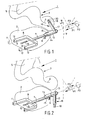
- Figs. 1 and 2 are perspective views of an infant vehicle seat 1 according to the invention, which comprises a frame 2 and a seat 3 connected to the frame 2.
- the seat 3 comprises a seat portion 4 and a back portion 5.
- the seat 3 is known per se and is only schematically indicated, therefore.
- the frame 2 On a side remote from the seat 3, the frame 2 is provided with a substantially vertically extending pin 6, which is rigidly connected to the frame 2.
- the pin 6 extends through a slot formed in a rod 7, as a result of which the rod 7 is movable in the direction indicated by the arrow P1 and in the opposite direction with respect to the pin 6.
- the rod 7 is provided with a U-shaped bracket 8 on a side remote from the pin 6, which bracket is provided with connectors 11, 12 at ends 9, 10 remote from the rod 7.
- the connectors 11, 12 are known per se, for example from European patent application EP-A1-1,180,448 , being referred to as isofix connectors, for example, in the industry.
- the rod 7 On a side remote from the U-shaped bracket 8, the rod 7 is provided with a sleeve 13, which sleeve is pivotable about the rod 7 in the direction indicated by the arrow P2 and in the opposite direction.
- the sleeve 13 is provided with two slots 14, 15 of different length, which extend parallel to the longitudinal direction of the rod 7.
- the sleeve 13 On a side remote from the slots 14, 15, the sleeve 13 is provided with a support leg 16 extending transversely to the sleeve 13.
- the support leg 16 comprises a number of tubes 17, 18, which can telescope with respect to each other.
- said support leg 16 In the position of the support leg 16 that is shown in Fig. 1 , said support leg 16 is disposed on the same side of the frame 2 as the back portion 5.
- the support leg 16 includes an angle ⁇ with the vertical V of 30°.
- the relatively short slot 14 of the sleeve 13 surrounds the pin 6 that is rigidly connected to the frame 2.
- the rod 7 and the sleeve 13 connected thereto are pulled in the direction indicated by the arrow P1 by means of a spring 19 connected to the frame 2, as a result of which the slot 14 firmly surrounds the pin 6.
- the rod 7 connected to the sleeve 13 and the connectors 11, 12 connected to the rod 7 via the U-shaped bracket 8 are positioned under the frame 2 in such a manner that the connectors 11, 12 cannot be connected to mounting elements (not shown) present in a vehicle. Said mounting elements, which are to be connected to the connectors, are known per se and will not be discussed in more detail herein, therefore.
- the telescopic tubes 17, 18 In the storage position of the support leg 16 that is shown in Fig. 1 , the telescopic tubes 17, 18 have been telescoped, so that the support leg 16 is relatively short.
- the infant vehicle seat 1 is positioned on a seat of the vehicle. Subsequently, the support leg 16 is jointly moved with the sleeve 13 connected thereto in a direction indicated by the arrow P3, opposite the direction indicated by the arrow P1, against the spring force of the spring 19 until the slot 14 no longer surrounds the pin 6. Also the rod 7 and the U-shaped bracket 8 connected thereto and the connectors 11, 12 connected to said bracket undergo the same movement in the direction indicated by the arrow P3. Subsequently, the support leg 16 and the sleeve 13 are jointly pivoted about the rod 7 in the direction indicated by the arrow P2, until the slot 15 is positioned opposite the pin 6.
- the support leg 16, the sleeve 13, the rod 7, the U-shaped bracket 8 and the connectors 11, 12 connected thereto are moved in the direction indicated by the arrow P1 partially under the influence of the force exerted by the spring 19, until the pin 6 abuts against one end of the slot 15.
- the support leg 16 is now in the position that is shown in Fig. 2 , whilst the connectors 11, 12 are in a mounting position. In Fig. 1 , said mounting position is illustrated in dotted lines.
- the length of the support leg 16 must now be adjusted to such an extent that an end 20 of the tube 18 remote from the sleeve 13 is firmly supported on a floor of the vehicle. This will be done practically automatically by a user who has taken hold of the support leg 16.
- the tube 18 can slide out of the tube 17 automatically under the influence of the force of gravity, in which case a known ratchet mechanism prevents the tube 18 from sliding into the tube 17 again.
- the tube 18 can only be slid into the tube 17, for example with a view to subsequently moving the support leg to the storage position that is shown in Fig. 1 , by unlocking the ratchet mechanism.
- Each connector 11, 12 is provided with a draw link 21 extending parallel to the rod 7, which draw link 21 is pivotally connected to a lever 22 on a side remote from the connector 11, 12.
- the lever 22 is pivot-mounted to an arm 24 connected to the U-shaped bracket 8 by means of a pivot pin 23.
- An end of the lever 22 remote from the draw link 21 is supported in an elongated recess 25 of a rod 26 which is slidably accommodated in the rod 7.
- the rod 26 is provided with a spring 27 at an end remote from the recess 25, by means of which spring an operating knob 28 connected to the rod 26 is pressed in a direction out of the rod 7.
- a warning knob 29 Disposed within the operating knob 28 is a warning knob 29, which is pressed in a direction away from the rod 26 by means of a spring 30.
- the warning knob 29 preferably has a colour such as red, which functions to warn the user that not all the connectors 11, 12 have been moved to a locking position yet.
- the operating knob 28 preferably has a colour such as green, which indicates to the user that the connectors 11, 12 are in engagement with the mounting elements.
- the knob is 28, 29 serve as marking elements.
- the connector 11 takes up a position in which it is in engagement with the mounting element.
- the draw link 21 has been pulled into the connector 11 in the direction indicated by the arrow P11, causing the lever 22 to pivot about the pivot pin 23 in the direction indicated by the arrow P12, to a position in which it abuts against an end 31 of the recess 25 with one end.
- the other connector 12 is not in engagement with the mounting element yet, so that the draw link 21 has not been moved into the connector 12 in the direction indicated by the arrow P11 yet.
- the lever 22 remains in the tilted position as shown in Fig. 3 , in which an end of the lever 22 remote from the draw link 21 abuts against an end 32 of the recess 25 remote from the end 31.
- the warning knob 29 extends beyond an end of the rod 7, so that the red warning knob 29 is clearly visible to mark the fact that the connectors are not both in engagement with mounting elements yet.
- the support leg 16 extends transversely to the plane of the drawing at the moment when the connectors 11, 12 can be moved into engagement with the connecting elements.
- the support leg is shown in the plane of the drawing, however.
- Fig. 4 schematically shows a situation in which both connectors 11, 12 have been moved into engagement with mounting elements, as a result of which the two draw links 21 have moved into the connectors 11, 12 in the direction indicated by the arrow P11 and the two levers 22 have pivoted about the pivot pins 23 to the position that is shown in Fig. 4 .
- the rod 26 is moved jointly with the operating knob 28 in the direction indicated by the arrow P13 with respect to the rod 7 under the influence of the spring 27, until the ends of the levers 22 abut against the end 32 of the recess 25.
- the green operating knob 28 is slid over the red warning knob 29, so that it is mainly the green operating knob 28 that is visible, which indicates to a user that both of the connectors 11, 12 are correctly in engagement with the mounting elements.
- Fig. 5 shows a situation in which a user bumps against a warning knob 29, by accident, for example, thereby pressing the warning knob into the rod 7 over a relatively short distance.
- the warning knob 29 will be moved jointly with the operating knob 28 and the rod 26 in indicated by the arrow P14, opposite to the direction indicated by the arrow P13, whereupon the ends of the levers 22 come into contact with an end 31 of the recess 25.
- the levers 22 will not be pivoted about the pivot pins 23 in the directions indicated by the arrows P15 and P16, respectively, until the moment the warning knob 29 and the operating knob 28 are jointly pressed further in the direction indicated by the arrow P14 (as shown in Fig. 6 ) and into the rod 7, as a result of which pivoting the draw links 21 will move out of the connectors 11, 12 in the direction indicated by the arrow P17 and the connectors 11, 12 are jointly unlocked.
- the support leg 16 pivot to a right-hand side of the infant seat 1 instead of to the left-hand side thereof.
- the seat it is also possible to connect the seat to the frame in such a manner that the back portion is positioned near the support leg, in which case the infant present in the seat faces the rear while being transported.
Landscapes
- Engineering & Computer Science (AREA)
- Health & Medical Sciences (AREA)
- Child & Adolescent Psychology (AREA)
- General Health & Medical Sciences (AREA)
- Aviation & Aerospace Engineering (AREA)
- Transportation (AREA)
- Mechanical Engineering (AREA)
- Seats For Vehicles (AREA)
- Vehicle Waterproofing, Decoration, And Sanitation Devices (AREA)
- Passenger Equipment (AREA)
Abstract
Description
- The invention relates to an infant vehicle seat comprising a frame as well as connectors connected to the frame which, in use, can be detachably connected to mounting elements present in a vehicle.
- With such an infant vehicle seat, which is known from European patent application
EP-A1-1 180 448 , the frame is connected to two mounting elements present in the vehicle by means of the two connectors. The mounting elements are brackets, for example, which are connected to the chassis of the vehicle. The mounting elements are disposed between the back portion and the seat portion of the vehicle seat to which the infant vehicle seat is mounted. - With such an infant vehicle seat it is not ensured that both of the connectors are being connected to the mounting elements present in the vehicle.
- It is an object of the invention to make it possible in a simple manner to ensure that all connectors are locked in position.
- This object is being achieved by the infant vehicle seat according to the invention in that each connector is provided with a draw link pivotably connected to a lever on a side remote from the connector, whereby ends of the levers remote from the draw links to which they are connected, are located in an elongated recess of a rod which extends from a rear side of the infant vehicle seat disposed near the back portion to a front side remote from the rear side of the infant vehicle seat and parallel to the draw links, which rod is movable under the influence of a spring in a direction away from the connectors only if all connectors are connected to the mounting elements.
- Since the rod is only movable if all connectors are connected to the mounting elements, the rod indicates in a simple manner to a user that all connectors are well connected.
- By pushing against the rod against the spring force of the spring in a direction towards the connectors, the levers are being pivoted due to which the draw links are being pulled at so that all connectors are simultaneously being unlocked.
- An embodiment of the infant vehicle seat according to the invention is characterized in that the rod on a side remote from the recess is provided with an operating knob which is slidable over a warning knob only if both connectors are connected to the mounting elements.
- Preferably the operating knob is green whilst the warning knob is red so that it is clearly visible to a user if the connectors are correctly in engagement with the mounting elements when the operating knob has been slid over the warning knob. If the warning knob is still fully visible, this will indicate to a user that the connectors are not yet all in engagement with the mounting elements.
- The invention will be explained in more detail with reference to the drawing, in which:
-
Fig. 1 is a perspective view of an infant vehicle seat according to the invention, in which a support leg and connectors are in the storage position; -
Fig. 2 is a perspective view of the infant vehicle seat that is shown infig. 1 , in which the support leg is in the supporting position and the connectors are in the mounting position; -
Figs. 3-6 show different situations of the connecting and disconnecting of the connectors, wherein the situation of the connectors can be indicated by means of a marking element according to the invention. - In the figures, like parts are indicated by the same numerals.
-
Figs. 1 and 2 are perspective views of an infant vehicle seat 1 according to the invention, which comprises aframe 2 and aseat 3 connected to theframe 2. Theseat 3 comprises a seat portion 4 and aback portion 5. Theseat 3 is known per se and is only schematically indicated, therefore. On a side remote from theseat 3, theframe 2 is provided with a substantially vertically extendingpin 6, which is rigidly connected to theframe 2. Thepin 6 extends through a slot formed in arod 7, as a result of which therod 7 is movable in the direction indicated by the arrow P1 and in the opposite direction with respect to thepin 6. Therod 7 is provided with aU-shaped bracket 8 on a side remote from thepin 6, which bracket is provided withconnectors ends rod 7. Theconnectors EP-A1-1,180,448 , being referred to as isofix connectors, for example, in the industry. - On a side remote from the U-shaped
bracket 8, therod 7 is provided with asleeve 13, which sleeve is pivotable about therod 7 in the direction indicated by the arrow P2 and in the opposite direction. Thesleeve 13 is provided with twoslots rod 7. On a side remote from theslots sleeve 13 is provided with asupport leg 16 extending transversely to thesleeve 13. Thesupport leg 16 comprises a number oftubes - In the position of the
support leg 16 that is shown inFig. 1 , saidsupport leg 16 is disposed on the same side of theframe 2 as theback portion 5. Thesupport leg 16 includes an angle α with the vertical V of 30°. In this position of thesupport leg 16, the relativelyshort slot 14 of thesleeve 13 surrounds thepin 6 that is rigidly connected to theframe 2. Therod 7 and thesleeve 13 connected thereto are pulled in the direction indicated by the arrow P1 by means of aspring 19 connected to theframe 2, as a result of which theslot 14 firmly surrounds thepin 6. Therod 7 connected to thesleeve 13 and theconnectors rod 7 via the U-shapedbracket 8 are positioned under theframe 2 in such a manner that theconnectors support leg 16 that is shown inFig. 1 , thetelescopic tubes support leg 16 is relatively short. - If a user wishes to mount the infant vehicle seat 1 in a vehicle, the infant vehicle seat 1 is positioned on a seat of the vehicle. Subsequently, the
support leg 16 is jointly moved with thesleeve 13 connected thereto in a direction indicated by the arrow P3, opposite the direction indicated by the arrow P1, against the spring force of thespring 19 until theslot 14 no longer surrounds thepin 6. Also therod 7 and the U-shapedbracket 8 connected thereto and theconnectors support leg 16 and thesleeve 13 are jointly pivoted about therod 7 in the direction indicated by the arrow P2, until theslot 15 is positioned opposite thepin 6. Following that, thesupport leg 16, thesleeve 13, therod 7, theU-shaped bracket 8 and theconnectors spring 19, until thepin 6 abuts against one end of theslot 15. Thesupport leg 16 is now in the position that is shown inFig. 2 , whilst theconnectors Fig. 1 , said mounting position is illustrated in dotted lines. The length of thesupport leg 16 must now be adjusted to such an extent that anend 20 of thetube 18 remote from thesleeve 13 is firmly supported on a floor of the vehicle. This will be done practically automatically by a user who has taken hold of thesupport leg 16. It is possible, if desired, for thetube 18 to slide out of thetube 17 automatically under the influence of the force of gravity, in which case a known ratchet mechanism prevents thetube 18 from sliding into thetube 17 again. Thetube 18 can only be slid into thetube 17, for example with a view to subsequently moving the support leg to the storage position that is shown inFig. 1 , by unlocking the ratchet mechanism. - The operation of the
connectors U-shaped bracket 8 is shown more clearly inFig. 3 . Eachconnector draw link 21 extending parallel to therod 7, which drawlink 21 is pivotally connected to alever 22 on a side remote from theconnector lever 22 is pivot-mounted to anarm 24 connected to the U-shapedbracket 8 by means of apivot pin 23. An end of thelever 22 remote from thedraw link 21 is supported in anelongated recess 25 of arod 26 which is slidably accommodated in therod 7. Therod 26 is provided with aspring 27 at an end remote from therecess 25, by means of which spring anoperating knob 28 connected to therod 26 is pressed in a direction out of therod 7. Disposed within theoperating knob 28 is awarning knob 29, which is pressed in a direction away from therod 26 by means of aspring 30. Thewarning knob 29 preferably has a colour such as red, which functions to warn the user that not all theconnectors operating knob 28 preferably has a colour such as green, which indicates to the user that theconnectors Fig. 3 will now be explained in more detail with reference toFigs. 3-6 . - In the position that is shown in
Fig. 3 , theconnector 11 takes up a position in which it is in engagement with the mounting element. In this position, thedraw link 21 has been pulled into theconnector 11 in the direction indicated by the arrow P11, causing thelever 22 to pivot about thepivot pin 23 in the direction indicated by the arrow P12, to a position in which it abuts against anend 31 of therecess 25 with one end. - The
other connector 12 is not in engagement with the mounting element yet, so that thedraw link 21 has not been moved into theconnector 12 in the direction indicated by the arrow P11 yet. Thelever 22 remains in the tilted position as shown inFig. 3 , in which an end of thelever 22 remote from thedraw link 21 abuts against anend 32 of therecess 25 remote from theend 31. Thewarning knob 29 extends beyond an end of therod 7, so that thered warning knob 29 is clearly visible to mark the fact that the connectors are not both in engagement with mounting elements yet. - For the sake of completeness it is noted with regard to
Fig. 3 that thesupport leg 16 extends transversely to the plane of the drawing at the moment when theconnectors leg 16, the support leg is shown in the plane of the drawing, however. -
Fig. 4 schematically shows a situation in which bothconnectors draw links 21 have moved into theconnectors levers 22 have pivoted about thepivot pins 23 to the position that is shown inFig. 4 . As soon as the two levers take up the position that is shown inFig. 4 , therod 26 is moved jointly with theoperating knob 28 in the direction indicated by the arrow P13 with respect to therod 7 under the influence of thespring 27, until the ends of thelevers 22 abut against theend 32 of therecess 25. Thegreen operating knob 28 is slid over thered warning knob 29, so that it is mainly thegreen operating knob 28 that is visible, which indicates to a user that both of theconnectors -
Fig. 5 shows a situation in which a user bumps against a warningknob 29, by accident, for example, thereby pressing the warning knob into therod 7 over a relatively short distance. AsFig. 5 shows, the warningknob 29 will be moved jointly with the operatingknob 28 and therod 26 in indicated by the arrow P14, opposite to the direction indicated by the arrow P13, whereupon the ends of thelevers 22 come into contact with anend 31 of therecess 25. - The
levers 22 will not be pivoted about the pivot pins 23 in the directions indicated by the arrows P15 and P16, respectively, until the moment the warningknob 29 and the operatingknob 28 are jointly pressed further in the direction indicated by the arrow P14 (as shown inFig. 6 ) and into therod 7, as a result of which pivoting the draw links 21 will move out of theconnectors connectors - The mechanism shown in
Figs. 3-6 thus makes it possible in a simple manner to ensure that both of theconnectors connectors - If the
sleeve 13 is provided with afurther slot 14, it is possible to have thesupport leg 16 pivot to a right-hand side of the infant seat 1 instead of to the left-hand side thereof. - Instead of using a
single support leg 16, it is also possible to provide theU-shaped bracket 8 with tworods 7 extending parallel to each other, in which case asupport leg 16 is attached to eachrod 7 in the manner as indicated above. - It is also possible to tilt the
support leg 16 to a position under theframe 2, with the tilting movement of thesupport leg 16 to the storage position resulting in simultaneous movement of theconnectors Fig. 2 to the storage position as shown inFig. 1 . - It is also possible to connect the support leg removably to the
frame 2, in which case theconnectors frame 2, whilst theconnectors support leg 16. - It is also possible to have the
support leg 16 rest on a front side of the vehicle seat instead of on a floor of the vehicle. - It is also possible to connect the seat to the frame in such a manner that the back portion is positioned near the support leg, in which case the infant present in the seat faces the rear while being transported.
Claims (3)
- An infant vehicle seat (3) comprising a frame (2) as well as connectors (11, 12) connected to the frame (2) which, in use, can be detachably connected to mounting elements present in a vehicle, characterized in that each connector (11, 12) is provided with a draw link (21) pivotably connected to a lever (22) on a side remote from the connector (11, 12), whereby ends of the levers (22) remote from the draw links (21) to which they are connected, are located in an elongated recess (25) of a rod (26) which extends from a rear side of the infant vehicle seat (3) disposed near the back portion to a front side remote from the rear side of the infant vehicle seat (3) and parallel to the draw links (21), which rod (26) is movable under the influence of a spring (27) in a direction away from the connectors (11, 12) only if all connectors (11, 12) are connected to the mounting elements.
- An infant vehicle seat (3) according to claim 1, characterized in that the rod (26) on a side remote from the recess (25) is provided with an operating knob (28) which is slidable over a warning knob (29) only if all connectors (11, 12) are connected to the mounting elements.
- An infant vehicle seat (3) according to claim 1 or 2, characterized in that the operating element is connected to a support leg (16).
Applications Claiming Priority (2)
| Application Number | Priority Date | Filing Date | Title |
|---|---|---|---|
| NL1023422A NL1023422C2 (en) | 2003-05-14 | 2003-05-14 | Children's vehicle seat. |
| EP04076380A EP1477356B1 (en) | 2003-05-14 | 2004-05-10 | Infant vehicle seat |
Related Parent Applications (2)
| Application Number | Title | Priority Date | Filing Date |
|---|---|---|---|
| EP04076380.7 Division | 2004-05-10 | ||
| EP04076380A Division EP1477356B1 (en) | 2003-05-14 | 2004-05-10 | Infant vehicle seat |
Publications (3)
| Publication Number | Publication Date |
|---|---|
| EP1930205A2 true EP1930205A2 (en) | 2008-06-11 |
| EP1930205A3 EP1930205A3 (en) | 2009-05-27 |
| EP1930205B1 EP1930205B1 (en) | 2011-07-20 |
Family
ID=33029108
Family Applications (2)
| Application Number | Title | Priority Date | Filing Date |
|---|---|---|---|
| EP08075202A Expired - Lifetime EP1930205B1 (en) | 2003-05-14 | 2004-05-10 | Infant vehicle seat |
| EP04076380A Expired - Lifetime EP1477356B1 (en) | 2003-05-14 | 2004-05-10 | Infant vehicle seat |
Family Applications After (1)
| Application Number | Title | Priority Date | Filing Date |
|---|---|---|---|
| EP04076380A Expired - Lifetime EP1477356B1 (en) | 2003-05-14 | 2004-05-10 | Infant vehicle seat |
Country Status (7)
| Country | Link |
|---|---|
| EP (2) | EP1930205B1 (en) |
| AT (2) | ATE516989T1 (en) |
| DE (1) | DE602004018705D1 (en) |
| ES (1) | ES2319525T3 (en) |
| NL (1) | NL1023422C2 (en) |
| PL (1) | PL1477356T3 (en) |
| PT (1) | PT1477356E (en) |
Cited By (3)
| Publication number | Priority date | Publication date | Assignee | Title |
|---|---|---|---|---|
| US11345262B2 (en) * | 2019-09-17 | 2022-05-31 | Wonderland Switzerland Ag | Infant car seat and release actuator |
| US11691543B2 (en) | 2020-04-14 | 2023-07-04 | Wonderland Switzerland Ag | Infant car seat and stability leg and release actuator |
| USD1074287S1 (en) | 2020-09-17 | 2025-05-13 | Wonderland Switzerland Ag | Base for infant car seat |
Families Citing this family (7)
| Publication number | Priority date | Publication date | Assignee | Title |
|---|---|---|---|---|
| NL1028788C2 (en) * | 2005-04-18 | 2006-10-20 | Maxi Miliaan Bv | Undercarriage as well as child vehicle seat provided with such an undercarriage. |
| NL1036452C2 (en) | 2009-01-23 | 2010-07-26 | Maxi Miliaan Bv | A child vehicle seat as well as a chassis suitable for such a child vehicle seat. |
| DE202009001975U1 (en) | 2009-03-17 | 2009-05-28 | Curt Würstl Vermögensverwaltungs-Gmbh & Co. Kg | Seat anchoring element for child safety seats or baby carrier |
| DE102009003629B4 (en) | 2009-03-17 | 2013-03-21 | Curt Würstl Vermögensverwaltungs-Gmbh & Co. Kg | Seat anchoring element for child safety seats or baby carrier |
| DE202010008803U1 (en) | 2010-10-13 | 2011-01-13 | Curt Würstl Vermögensverwaltungs-Gmbh & Co. Kg | Seat anchoring element for child safety seats or baby carrier |
| DE202012101091U1 (en) | 2012-03-27 | 2012-05-31 | Curt Würstl Vermögensverwaltungs-Gmbh & Co. Kg | fastening device |
| CN113002383B (en) * | 2019-12-18 | 2023-06-30 | 宝钜瑞士股份有限公司 | Child safety seat |
Citations (1)
| Publication number | Priority date | Publication date | Assignee | Title |
|---|---|---|---|---|
| EP1180448A1 (en) | 2000-08-09 | 2002-02-20 | Takata Corporation | Child seat base |
Family Cites Families (9)
| Publication number | Priority date | Publication date | Assignee | Title |
|---|---|---|---|---|
| GB9424050D0 (en) * | 1994-11-29 | 1995-01-18 | Britax Roemer Kindersicherheit Gmbh | Child safety seat |
| DE19744978C2 (en) * | 1997-10-14 | 2003-03-27 | Van Riesen Gmbh U Co Kg | adapter |
| DE69919942T2 (en) * | 1998-07-06 | 2005-11-17 | Bröderna Holmbergs Fabriks AB | Fastening device for a child safety seat |
| DE19834861C1 (en) * | 1998-08-01 | 1999-08-05 | Keiper Gmbh & Co | Vehicle child seat |
| JP3371850B2 (en) * | 1999-01-29 | 2003-01-27 | タカタ株式会社 | child seat |
| JP3656512B2 (en) * | 1999-05-10 | 2005-06-08 | タカタ株式会社 | child seat |
| DE19946579A1 (en) * | 1999-09-29 | 2001-04-05 | Opel Adam Ag | Device for fastening child's seat in motor vehicle has adapter with two components aligning with seat buckle sections of child's seat, and on other side two length-adjustable locking units aligning with retaining elements on main seat |
| JP2001206117A (en) * | 2000-01-27 | 2001-07-31 | Honda Motor Co Ltd | Attachment for infant seat |
| ES2196999A1 (en) * | 2002-03-14 | 2003-12-16 | Play Sa | Child seat for vehicles |
-
2003
- 2003-05-14 NL NL1023422A patent/NL1023422C2/en not_active IP Right Cessation
-
2004
- 2004-05-10 AT AT08075202T patent/ATE516989T1/en not_active IP Right Cessation
- 2004-05-10 PT PT04076380T patent/PT1477356E/en unknown
- 2004-05-10 EP EP08075202A patent/EP1930205B1/en not_active Expired - Lifetime
- 2004-05-10 AT AT04076380T patent/ATE419140T1/en not_active IP Right Cessation
- 2004-05-10 DE DE602004018705T patent/DE602004018705D1/en not_active Expired - Lifetime
- 2004-05-10 ES ES04076380T patent/ES2319525T3/en not_active Expired - Lifetime
- 2004-05-10 EP EP04076380A patent/EP1477356B1/en not_active Expired - Lifetime
- 2004-05-10 PL PL04076380T patent/PL1477356T3/en unknown
Patent Citations (1)
| Publication number | Priority date | Publication date | Assignee | Title |
|---|---|---|---|---|
| EP1180448A1 (en) | 2000-08-09 | 2002-02-20 | Takata Corporation | Child seat base |
Cited By (8)
| Publication number | Priority date | Publication date | Assignee | Title |
|---|---|---|---|---|
| US11345262B2 (en) * | 2019-09-17 | 2022-05-31 | Wonderland Switzerland Ag | Infant car seat and release actuator |
| US11738668B2 (en) | 2019-09-17 | 2023-08-29 | Wonderland Switzerland Ag | Infant car seat and release actuator |
| US12291133B2 (en) | 2019-09-17 | 2025-05-06 | Wonderland Switzerland Ag | Infant car seat and release actuator |
| US11691543B2 (en) | 2020-04-14 | 2023-07-04 | Wonderland Switzerland Ag | Infant car seat and stability leg and release actuator |
| US12077070B2 (en) | 2020-04-14 | 2024-09-03 | Wonderland Switzerland Ag | Infant car seat and stability leg and release actuator |
| US12115890B2 (en) | 2020-04-14 | 2024-10-15 | Wonderland Switzerland Ag | Infant car seat and stability leg and release actuator |
| US12311811B2 (en) | 2020-04-14 | 2025-05-27 | Wonderland Switzerland Ag | Infant car seat and stability leg and release actuator |
| USD1074287S1 (en) | 2020-09-17 | 2025-05-13 | Wonderland Switzerland Ag | Base for infant car seat |
Also Published As
| Publication number | Publication date |
|---|---|
| EP1930205B1 (en) | 2011-07-20 |
| EP1477356B1 (en) | 2008-12-31 |
| ES2319525T3 (en) | 2009-05-08 |
| NL1023422C2 (en) | 2004-11-16 |
| EP1477356A1 (en) | 2004-11-17 |
| DE602004018705D1 (en) | 2009-02-12 |
| ATE419140T1 (en) | 2009-01-15 |
| PL1477356T3 (en) | 2009-06-30 |
| EP1930205A3 (en) | 2009-05-27 |
| PT1477356E (en) | 2009-03-06 |
| ATE516989T1 (en) | 2011-08-15 |
Similar Documents
| Publication | Publication Date | Title |
|---|---|---|
| EP1930205B1 (en) | Infant vehicle seat | |
| US7258617B2 (en) | Child swing with a child seat removable to serve as a car seat | |
| EP1986908B1 (en) | Stroller | |
| US7328946B2 (en) | Chassis as well as a child vehicle seat provided with such a chassis | |
| US6830254B2 (en) | Stroller with an adjustable backrest | |
| EP0010867A1 (en) | An armrest assembly for a seat | |
| EP2210768A2 (en) | Child vehicle seat | |
| CN115848245A (en) | Child seat system comprising a seat element and a base mountable on a vehicle seat | |
| EP0757641A1 (en) | Pram | |
| EP2241492A2 (en) | A tandem stroller frame with an inclination adjustable second seat | |
| EP2135794A1 (en) | Stroller | |
| CN106671745A (en) | Windscreen installation apparatus and method | |
| JP6381126B2 (en) | Vehicle seat | |
| KR20210121165A (en) | Child safety seat assembly | |
| EP1369294B1 (en) | A chassis suitable for attaching an infant vehicle seat to a vehicle seat, such an assembly and an infant vehicle seat | |
| DK2895376T3 (en) | Seat and stroller or pram with such a seat | |
| GB2210783A (en) | Car seat having a variable angle back rest | |
| EP1369293B1 (en) | Infant vehicle seat comprising a chassis and a seat connected to the chassis, as well as such a chassis | |
| EP1369295B1 (en) | A chassis suitable for attaching an infant vehicle seat to a vehicle seat, such an assembly and an infant vehicle seat | |
| EP1475267B1 (en) | Child safety seat | |
| CN103386905A (en) | Child vehicle seat, and seat and base suitable for such a child vehicle seat | |
| GB2030853A (en) | A chair with adjustable foot rest | |
| JPS5832065B2 (en) | baby carriage | |
| CN106256650B (en) | Baby carriage frame | |
| WO2011107005A1 (en) | Step tread regulating mechanism of baby stroller |
Legal Events
| Date | Code | Title | Description |
|---|---|---|---|
| PUAI | Public reference made under article 153(3) epc to a published international application that has entered the european phase |
Free format text: ORIGINAL CODE: 0009012 |
|
| 17P | Request for examination filed |
Effective date: 20080319 |
|
| AC | Divisional application: reference to earlier application |
Ref document number: 1477356 Country of ref document: EP Kind code of ref document: P |
|
| AK | Designated contracting states |
Kind code of ref document: A2 Designated state(s): AT BE BG CH CY CZ DE DK EE ES FI FR GB GR HU IE IT LI LU MC NL PL PT RO SE SI SK TR |
|
| AX | Request for extension of the european patent |
Extension state: AL HR LT LV MK |
|
| PUAL | Search report despatched |
Free format text: ORIGINAL CODE: 0009013 |
|
| AK | Designated contracting states |
Kind code of ref document: A3 Designated state(s): AT BE BG CH CY CZ DE DK EE ES FI FR GB GR HU IE IT LI LU MC NL PL PT RO SE SI SK TR |
|
| AX | Request for extension of the european patent |
Extension state: AL HR LT LV MK |
|
| 17Q | First examination report despatched |
Effective date: 20090828 |
|
| AKX | Designation fees paid |
Designated state(s): AT BE BG CH CY CZ DE DK EE ES FI FR GB GR HU IE IT LI LU MC NL PL PT RO SE SI SK TR |
|
| GRAP | Despatch of communication of intention to grant a patent |
Free format text: ORIGINAL CODE: EPIDOSNIGR1 |
|
| GRAS | Grant fee paid |
Free format text: ORIGINAL CODE: EPIDOSNIGR3 |
|
| GRAA | (expected) grant |
Free format text: ORIGINAL CODE: 0009210 |
|
| AC | Divisional application: reference to earlier application |
Ref document number: 1477356 Country of ref document: EP Kind code of ref document: P |
|
| AK | Designated contracting states |
Kind code of ref document: B1 Designated state(s): AT BE BG CH CY CZ DE DK EE ES FI FR GB GR HU IE IT LI LU MC NL PL PT RO SE SI SK TR |
|
| REG | Reference to a national code |
Ref country code: GB Ref legal event code: FG4D |
|
| REG | Reference to a national code |
Ref country code: CH Ref legal event code: EP |
|
| REG | Reference to a national code |
Ref country code: NL Ref legal event code: T3 |
|
| REG | Reference to a national code |
Ref country code: DE Ref legal event code: R096 Ref document number: 602004033587 Country of ref document: DE Effective date: 20110908 |
|
| REG | Reference to a national code |
Ref country code: AT Ref legal event code: MK05 Ref document number: 516989 Country of ref document: AT Kind code of ref document: T Effective date: 20110720 |
|
| PG25 | Lapsed in a contracting state [announced via postgrant information from national office to epo] |
Ref country code: FI Free format text: LAPSE BECAUSE OF FAILURE TO SUBMIT A TRANSLATION OF THE DESCRIPTION OR TO PAY THE FEE WITHIN THE PRESCRIBED TIME-LIMIT Effective date: 20110720 Ref country code: BE Free format text: LAPSE BECAUSE OF FAILURE TO SUBMIT A TRANSLATION OF THE DESCRIPTION OR TO PAY THE FEE WITHIN THE PRESCRIBED TIME-LIMIT Effective date: 20110720 Ref country code: SE Free format text: LAPSE BECAUSE OF FAILURE TO SUBMIT A TRANSLATION OF THE DESCRIPTION OR TO PAY THE FEE WITHIN THE PRESCRIBED TIME-LIMIT Effective date: 20110720 Ref country code: PT Free format text: LAPSE BECAUSE OF FAILURE TO SUBMIT A TRANSLATION OF THE DESCRIPTION OR TO PAY THE FEE WITHIN THE PRESCRIBED TIME-LIMIT Effective date: 20111121 |
|
| PG25 | Lapsed in a contracting state [announced via postgrant information from national office to epo] |
Ref country code: PL Free format text: LAPSE BECAUSE OF FAILURE TO SUBMIT A TRANSLATION OF THE DESCRIPTION OR TO PAY THE FEE WITHIN THE PRESCRIBED TIME-LIMIT Effective date: 20110720 Ref country code: SI Free format text: LAPSE BECAUSE OF FAILURE TO SUBMIT A TRANSLATION OF THE DESCRIPTION OR TO PAY THE FEE WITHIN THE PRESCRIBED TIME-LIMIT Effective date: 20110720 Ref country code: AT Free format text: LAPSE BECAUSE OF FAILURE TO SUBMIT A TRANSLATION OF THE DESCRIPTION OR TO PAY THE FEE WITHIN THE PRESCRIBED TIME-LIMIT Effective date: 20110720 Ref country code: CY Free format text: LAPSE BECAUSE OF FAILURE TO SUBMIT A TRANSLATION OF THE DESCRIPTION OR TO PAY THE FEE WITHIN THE PRESCRIBED TIME-LIMIT Effective date: 20110720 Ref country code: GR Free format text: LAPSE BECAUSE OF FAILURE TO SUBMIT A TRANSLATION OF THE DESCRIPTION OR TO PAY THE FEE WITHIN THE PRESCRIBED TIME-LIMIT Effective date: 20111021 |
|
| PG25 | Lapsed in a contracting state [announced via postgrant information from national office to epo] |
Ref country code: SK Free format text: LAPSE BECAUSE OF FAILURE TO SUBMIT A TRANSLATION OF THE DESCRIPTION OR TO PAY THE FEE WITHIN THE PRESCRIBED TIME-LIMIT Effective date: 20110720 Ref country code: CZ Free format text: LAPSE BECAUSE OF FAILURE TO SUBMIT A TRANSLATION OF THE DESCRIPTION OR TO PAY THE FEE WITHIN THE PRESCRIBED TIME-LIMIT Effective date: 20110720 |
|
| PLBE | No opposition filed within time limit |
Free format text: ORIGINAL CODE: 0009261 |
|
| STAA | Information on the status of an ep patent application or granted ep patent |
Free format text: STATUS: NO OPPOSITION FILED WITHIN TIME LIMIT |
|
| PG25 | Lapsed in a contracting state [announced via postgrant information from national office to epo] |
Ref country code: IT Free format text: LAPSE BECAUSE OF FAILURE TO SUBMIT A TRANSLATION OF THE DESCRIPTION OR TO PAY THE FEE WITHIN THE PRESCRIBED TIME-LIMIT Effective date: 20110720 Ref country code: EE Free format text: LAPSE BECAUSE OF FAILURE TO SUBMIT A TRANSLATION OF THE DESCRIPTION OR TO PAY THE FEE WITHIN THE PRESCRIBED TIME-LIMIT Effective date: 20110720 Ref country code: RO Free format text: LAPSE BECAUSE OF FAILURE TO SUBMIT A TRANSLATION OF THE DESCRIPTION OR TO PAY THE FEE WITHIN THE PRESCRIBED TIME-LIMIT Effective date: 20110720 |
|
| 26N | No opposition filed |
Effective date: 20120423 |
|
| PG25 | Lapsed in a contracting state [announced via postgrant information from national office to epo] |
Ref country code: DK Free format text: LAPSE BECAUSE OF FAILURE TO SUBMIT A TRANSLATION OF THE DESCRIPTION OR TO PAY THE FEE WITHIN THE PRESCRIBED TIME-LIMIT Effective date: 20110720 |
|
| REG | Reference to a national code |
Ref country code: DE Ref legal event code: R097 Ref document number: 602004033587 Country of ref document: DE Effective date: 20120423 |
|
| PG25 | Lapsed in a contracting state [announced via postgrant information from national office to epo] |
Ref country code: MC Free format text: LAPSE BECAUSE OF NON-PAYMENT OF DUE FEES Effective date: 20120531 |
|
| REG | Reference to a national code |
Ref country code: CH Ref legal event code: PL |
|
| PG25 | Lapsed in a contracting state [announced via postgrant information from national office to epo] |
Ref country code: CH Free format text: LAPSE BECAUSE OF NON-PAYMENT OF DUE FEES Effective date: 20120531 Ref country code: LI Free format text: LAPSE BECAUSE OF NON-PAYMENT OF DUE FEES Effective date: 20120531 |
|
| REG | Reference to a national code |
Ref country code: IE Ref legal event code: MM4A |
|
| PG25 | Lapsed in a contracting state [announced via postgrant information from national office to epo] |
Ref country code: ES Free format text: LAPSE BECAUSE OF FAILURE TO SUBMIT A TRANSLATION OF THE DESCRIPTION OR TO PAY THE FEE WITHIN THE PRESCRIBED TIME-LIMIT Effective date: 20111031 Ref country code: IE Free format text: LAPSE BECAUSE OF NON-PAYMENT OF DUE FEES Effective date: 20120510 |
|
| PG25 | Lapsed in a contracting state [announced via postgrant information from national office to epo] |
Ref country code: BG Free format text: LAPSE BECAUSE OF FAILURE TO SUBMIT A TRANSLATION OF THE DESCRIPTION OR TO PAY THE FEE WITHIN THE PRESCRIBED TIME-LIMIT Effective date: 20111020 |
|
| PG25 | Lapsed in a contracting state [announced via postgrant information from national office to epo] |
Ref country code: TR Free format text: LAPSE BECAUSE OF FAILURE TO SUBMIT A TRANSLATION OF THE DESCRIPTION OR TO PAY THE FEE WITHIN THE PRESCRIBED TIME-LIMIT Effective date: 20110720 |
|
| PG25 | Lapsed in a contracting state [announced via postgrant information from national office to epo] |
Ref country code: LU Free format text: LAPSE BECAUSE OF NON-PAYMENT OF DUE FEES Effective date: 20120510 |
|
| PG25 | Lapsed in a contracting state [announced via postgrant information from national office to epo] |
Ref country code: HU Free format text: LAPSE BECAUSE OF FAILURE TO SUBMIT A TRANSLATION OF THE DESCRIPTION OR TO PAY THE FEE WITHIN THE PRESCRIBED TIME-LIMIT Effective date: 20040510 |
|
| REG | Reference to a national code |
Ref country code: FR Ref legal event code: PLFP Year of fee payment: 13 |
|
| PGFP | Annual fee paid to national office [announced via postgrant information from national office to epo] |
Ref country code: NL Payment date: 20160421 Year of fee payment: 13 |
|
| PGFP | Annual fee paid to national office [announced via postgrant information from national office to epo] |
Ref country code: GB Payment date: 20160520 Year of fee payment: 13 Ref country code: DE Payment date: 20160520 Year of fee payment: 13 |
|
| PGFP | Annual fee paid to national office [announced via postgrant information from national office to epo] |
Ref country code: FR Payment date: 20160520 Year of fee payment: 13 |
|
| REG | Reference to a national code |
Ref country code: DE Ref legal event code: R119 Ref document number: 602004033587 Country of ref document: DE |
|
| REG | Reference to a national code |
Ref country code: NL Ref legal event code: MM Effective date: 20170601 |
|
| GBPC | Gb: european patent ceased through non-payment of renewal fee |
Effective date: 20170510 |
|
| REG | Reference to a national code |
Ref country code: FR Ref legal event code: ST Effective date: 20180131 |
|
| PG25 | Lapsed in a contracting state [announced via postgrant information from national office to epo] |
Ref country code: NL Free format text: LAPSE BECAUSE OF NON-PAYMENT OF DUE FEES Effective date: 20170601 |
|
| PG25 | Lapsed in a contracting state [announced via postgrant information from national office to epo] |
Ref country code: GB Free format text: LAPSE BECAUSE OF NON-PAYMENT OF DUE FEES Effective date: 20170510 Ref country code: DE Free format text: LAPSE BECAUSE OF NON-PAYMENT OF DUE FEES Effective date: 20171201 |
|
| PG25 | Lapsed in a contracting state [announced via postgrant information from national office to epo] |
Ref country code: FR Free format text: LAPSE BECAUSE OF NON-PAYMENT OF DUE FEES Effective date: 20170531 |