EP1929953A1 - Ultrasonograph - Google Patents
Ultrasonograph Download PDFInfo
- Publication number
- EP1929953A1 EP1929953A1 EP06745715A EP06745715A EP1929953A1 EP 1929953 A1 EP1929953 A1 EP 1929953A1 EP 06745715 A EP06745715 A EP 06745715A EP 06745715 A EP06745715 A EP 06745715A EP 1929953 A1 EP1929953 A1 EP 1929953A1
- Authority
- EP
- European Patent Office
- Prior art keywords
- luminance value
- diagnostic apparatus
- ultrasound
- ultrasound diagnostic
- luminance
- Prior art date
- Legal status (The legal status is an assumption and is not a legal conclusion. Google has not performed a legal analysis and makes no representation as to the accuracy of the status listed.)
- Granted
Links
Images



Classifications
-
- A—HUMAN NECESSITIES
- A61—MEDICAL OR VETERINARY SCIENCE; HYGIENE
- A61B—DIAGNOSIS; SURGERY; IDENTIFICATION
- A61B8/00—Diagnosis using ultrasonic, sonic or infrasonic waves
- A61B8/06—Measuring blood flow
-
- G—PHYSICS
- G01—MEASURING; TESTING
- G01S—RADIO DIRECTION-FINDING; RADIO NAVIGATION; DETERMINING DISTANCE OR VELOCITY BY USE OF RADIO WAVES; LOCATING OR PRESENCE-DETECTING BY USE OF THE REFLECTION OR RERADIATION OF RADIO WAVES; ANALOGOUS ARRANGEMENTS USING OTHER WAVES
- G01S15/00—Systems using the reflection or reradiation of acoustic waves, e.g. sonar systems
- G01S15/88—Sonar systems specially adapted for specific applications
- G01S15/89—Sonar systems specially adapted for specific applications for mapping or imaging
- G01S15/8906—Short-range imaging systems; Acoustic microscope systems using pulse-echo techniques
- G01S15/8979—Combined Doppler and pulse-echo imaging systems
-
- G—PHYSICS
- G01—MEASURING; TESTING
- G01S—RADIO DIRECTION-FINDING; RADIO NAVIGATION; DETERMINING DISTANCE OR VELOCITY BY USE OF RADIO WAVES; LOCATING OR PRESENCE-DETECTING BY USE OF THE REFLECTION OR RERADIATION OF RADIO WAVES; ANALOGOUS ARRANGEMENTS USING OTHER WAVES
- G01S7/00—Details of systems according to groups G01S13/00, G01S15/00, G01S17/00
- G01S7/52—Details of systems according to groups G01S13/00, G01S15/00, G01S17/00 of systems according to group G01S15/00
- G01S7/52017—Details of systems according to groups G01S13/00, G01S15/00, G01S17/00 of systems according to group G01S15/00 particularly adapted to short-range imaging
- G01S7/52053—Display arrangements
- G01S7/52057—Cathode ray tube displays
- G01S7/52071—Multicolour displays; using colour coding; Optimising colour or information content in displays, e.g. parametric imaging
Definitions
- the present invention relates to an ultrasound diagnostic apparatus, particularly to an ultrasound diagnostic apparatus having a function of showing dynamic blood flow in a living body.
- an ultrasound diagnostic apparatus which irradiates ultrasound into a living body and receives a reflected wave of the ultrasound reflected at a tissue of the living body to obtain a tomogram of the living body.
- an ultrasound diagnostic apparatus which has a function of displaying, besides the tomogram of a living body, for example, dynamic blood flow in a living body as a blood flow image by exploiting the Doppler effect by which the frequency of a reflected wave is shifted due to the moving velocity of a reflecting object in motion.
- a blood-flow velocity display apparatus proposed in Japanese Patent Publication No. 06-9556 is widely known.
- the blood-flow velocity display apparatus of Japanese Patent Publication No. 06-9556 is configured such that after a comparison between the magnitudes of a blood-flow velocity calculation value during a current scan and a blood-flow velocity display value during the previous scan is performed by blood-flow velocity display value calculation means, a blood-flow velocity display value is calculated based on the aforementioned comparison result and is used to display a blood flow image on a color monitor.
- a blood-flow velocity display value is calculated based on the aforementioned comparison result and is used to display a blood flow image on a color monitor.
- the blood-flow velocity display apparatus of Japanese Patent Publication No. 06-9556 performs the comparison by the blood-flow velocity display value calculation means and the calculation based on the comparison result to display a blood flow image, the processing load on the blood-flow velocity display value calculation means tends to increase, thus the frame rate of the blood flow image may be reduced. This will result in a problem that the blood-flow velocity display apparatus of Japanese Patent Publication No. 06-9556 may not be able to accurately display dynamic blood flow.
- the present invention has been made in view of the above described problem and its object is to provide an ultrasound diagnostic apparatus which enables to display dynamic blood flow more accurately than ever without sacrificing the frame rate of blood flow image.
- the ultrasound diagnostic apparatus of a first aspect of the present invention includes: ultrasound transmitting/receiving means for transmitting an ultrasound pulse to generate ultrasound to be transmitted from ultrasound transducing means to a test subject, and receiving an echo signal outputted from the ultrasound transducing means based on the ultrasound reflected in the test subject; based on the echo signal, dynamic blood flow detection means for calculating a predetermined detection value based on dynamic blood flow in the test subject; luminance value conversion means for converting the predetermined detection value into a luminance value; luminance value replacement means retaining luminance value conversion information for converting one luminance value to another luminance value; and comparison means for comparing a first luminance value in one frame with a second luminance value in the frame immediately preceding the one frame, out of luminance values outputted from the luminance value conversion means, wherein the comparison means is adapted to output either the first luminance value or a third luminance value, which is not larger than the absolute value of the second luminance value, based on the comparison result and the luminance value replacement information.
- the ultrasound diagnostic apparatus of a second aspect of the present invention is the ultrasound diagnostic apparatus according to the first aspect of the present invention, wherein the comparison means is adapted to output the first luminance value when obtaining a comparison result that the first luminance value is larger than the second luminance value, and to replace the second luminance value with the third luminance value based on the luminance value replacement information, thereby outputting the third luminance value when obtaining a comparison result that the first luminance value is not larger than the second luminance value.
- the ultrasound diagnostic apparatus of a third aspect of the present invention is the ultrasound diagnostic apparatus according to the second aspect of the present invention, wherein the comparison means is adapted to increase the attenuation of the third luminance value as the second luminance value increases when replacing the second luminance value with the third luminance value based on the luminance value replacement information.
- the ultrasound diagnostic apparatus of a fourth aspect of the present invention is the ultrasound diagnostic apparatus according to the second aspect of the present invention, wherein the luminance value replacement information retained by the luminance value replacement means is configured to be a rewritable data file.
- the ultrasound diagnostic apparatus of a fifth aspect of the present invention is the ultrasound diagnostic apparatus according to the third aspect of the present invention, wherein the luminance value replacement information retained by the luminance value replacement means is configured to be a rewritable data file.
- the ultrasound diagnostic apparatus of a sixth aspect of the present invention is the ultrasound apparatus according to the fourth aspect of the present invention, wherein the data file is made up of a plurality of data files.
- the ultrasound diagnostic apparatus of a seventh aspect of the present invention is the ultrasound apparatus according to the fifth aspect of the present invention, wherein the data file is made up of a plurality of data files.
- the ultrasound diagnostic apparatus of an eighth aspect of the present invention is the ultrasound diagnostic apparatus according to the first aspect of the present invention, wherein the comparison means is adapted to output the first luminance value when obtaining a comparison result that the first luminance value has a different sign from that of the second luminance value, or that the first luminance value has the same sign as that of the second luminance value and the absolute value of the first luminance value is larger than that of the second luminance value; and to replace the second luminance value with the third luminance value based on the luminance value replacement information and output the third luminance value, when obtaining a comparison result that the first luminance value has the same sign as that of the second luminance and the absolute value of the first luminance value is not larger than that of the second luminance value.
- the ultrasound diagnostic apparatus of a ninth aspect of the present invention is the ultrasound diagnostic apparatus according to the eighth aspect of the present invention, wherein the comparison means is adapted to increase the attenuation of the third luminance value as the second luminance value increases when replacing the second luminance value with the third luminance value based on the luminance value replacement information.
- the ultrasound diagnostic apparatus of a tenth aspect of the present invention is the ultrasound diagnostic apparatus according to the eighth aspect of the present invention, wherein the luminance value replacement information retained by the luminance value replacement means is configured to be a rewritable data file.
- the ultrasound diagnostic apparatus of an eleventh aspect of the present invention is the ultrasound diagnostic apparatus according to the ninth aspect of the present invention, wherein the luminance value replacement information retained by the luminance value replacement means is configured to be a rewritable data file.
- the ultrasound diagnostic apparatus of a twelfth aspect of the present invention is the ultrasound diagnostic apparatus according to the tenth aspect of the present invention, wherein the data file is made up of a plurality of data files.
- the ultrasound diagnostic apparatus of a thirteenth aspect of the present invention is the ultrasound diagnostic apparatus according to the eleventh aspect of the present invention, wherein the data file is made up of a plurality of data files.
- the ultrasound diagnostic apparatus of a fourteenth aspect of the present invention is the ultrasound diagnostic apparatus according to the first aspect of the present invention, wherein the luminance value replacement information retained by the luminance value replacement means is configured to be a rewritable data file.
- the ultrasound diagnostic apparatus of a fifteenth aspect of the present invention is the ultrasound diagnostic apparatus according to the fourteenth aspect of the present invention, wherein the data file is made up of a plurality of data files.
- the ultrasound diagnostic apparatus of a sixteenth aspect of the present invention includes: ultrasound transmitting/receiving means for transmitting an ultrasound pulse to generate ultrasound to be transmitted from ultrasound transducing means to a test subject, and receiving an echo signal outputted from the ultrasound transducing means based on the ultrasound reflected in the test subject; based on the echo signal, dynamic blood flow detection means for calculating a predetermined detection value based on dynamic blood flow in the test subject; luminance value conversion means for converting the predetermined detection value into a luminance value; storage means for storing a first luminance value in one frame and a second luminance value in the frame immediately preceding the one frame, out of the luminance values, and outputting the first luminance value and the second luminance value; luminance value replacement means for replacing the second luminance value outputted from the storage means with a third luminance value which is not larger than the second luminance value to output the third luminance value; and comparison means for comparing the first luminance value outputted from the storage means with the third luminance value outputted from the luminance value replacement
- the ultrasound diagnostic apparatus of a seventeenth aspect of the present invention is the ultrasound diagnostic apparatus according to the sixteenth aspect of the present invention, wherein the comparison means is adapted to increase the attenuation of the third luminance value as the second luminance value increases when replacing the second luminance value with the third luminance value based on the luminance value replacement information.
- the ultrasound diagnostic apparatus of an eighteenth aspect of the present invention is the ultrasound diagnostic apparatus according to the sixteenth aspect of the present invention, wherein the luminance value replacement information retained by the luminance value replacement means is configured to be a rewritable data file.
- the ultrasound diagnostic apparatus of a nineteenth aspect of the present invention is the ultrasound diagnostic apparatus according to the seventeenth aspect of the present invention, wherein the luminance value replacement information retained by the luminance value replacement means is configured to be a rewritable data file.
- the ultrasound diagnostic apparatus of a twentieth aspect of the present invention is the ultrasound diagnostic apparatus according to the eighteenth aspect of the present invention, wherein the data file is made up of a plurality of data files.
- the ultrasound diagnostic apparatus of a twenty-first aspect of the present invention is the ultrasound diagnostic apparatus according to the nineteenth aspect of the present invention, wherein the data file is made up of a plurality of data files.
- the ultrasound diagnostic apparatus of a twenty-second aspect of the present invention includes: ultrasound transmitting/receiving means for transmitting an ultrasound pulse to generate ultrasound to be transmitted from ultrasound transducing means to a test subject, and receiving an echo signal outputted from the ultrasound transducing means based on the ultrasound reflected in the test subject; based on the echo signal, dynamic blood flow detection means for calculating a predetermined detection value based on dynamic blood flow in the test subject; luminance value conversion means for converting the predetermined detection value into a luminance value; and comparison means for comparing a first luminance value in one frame with a second luminance value in the frame immediately preceding the one frame, out of the luminance values outputted from the luminance value conversion means, wherein the ultrasound diagnostic apparatus further includes a lookup table including a comparative table for converting the second luminance value into a third luminance value which is not larger than the absolute value of the second luminance value, and wherein the comparison means outputs either the first luminance value or the third luminance value based on the comparison result and the comparativ
- the ultrasound diagnostic apparatus of a twenty-third aspect of the present invention is the ultrasound diagnostic apparatus according to the twenty-second aspect of the present invention, wherein the comparative table retained by the lookup table is configured to be a rewritable data file.
- the ultrasound diagnostic apparatus of a twenty-fourth aspect of the present invention is the ultrasound diagnostic apparatus according to the twenty-third aspect of the present invention, wherein the data file is made up of a plurality of data files.
- Fig. 1 shows the configuration of principal parts of an ultrasound diagnostic system in which the ultrasound diagnostic apparatus relating to a present embodiment is used.
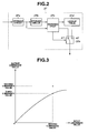
- Fig. 2 shows a configuration example of an after image processing circuit included in the ultrasound diagnostic apparatus of Fig. 1 .
- Fig. 3 is a graph to show the relationship between the input luminance value and the output luminance value corresponding to the input luminance value in a comparative table included in the lookup table in the after image processing circuit of Fig. 2 .
- Fig. 4 is a graph to show the variation of the luminance value of the portion where blood flow exists, in a blood flow image displayed on a monitor.
- Fig. 5 shows a configuration example of a variation of the after image processing circuit of Fig. 2 .
- Fig. 6 shows another example, which is different from that of Fig. 5 , of a variation of the after image processing circuit of Fig. 2 .
- the ultrasound diagnostic system 1 is configured to include a probe 11, an ultrasound diagnostic apparatus 21, and a monitor 41.
- the probe 11 contains thereinside an ultrasound transducer 12 which transmits ultrasound to a test subject 101, for example, a living body, and receives a reflected wave of the ultrasound in the test subject 101.
- the ultrasound transducer 12 as the ultrasound transducing means transmits ultrasound to the test subject 101 based on the ultrasound pulse signal from the ultrasound diagnostic apparatus 21, and receives the reflected wave of the ultrasound in the test subject 101 to output it as an echo signal to the ultrasound diagnostic apparatus 21.
- the ultrasound diagnostic apparatus 21 is configured to include a transmitting/receiving circuit 22, a B-mode generation circuit 23, a Doppler processing circuit 24, and a synthesis circuit 25.
- the transmitting/receiving circuit 22 as ultrasound transmitting/receiving means transmits an ultrasound pulse signal for driving the ultrasound transducer 12 to the probe 11 and receives the echo signal outputted from the ultrasound transducer 12 to perform processing thereon amplification and the like, and outputs the processed echo signal to the B-mode generation circuit 23 and the Doppler processing circuit 24.
- the B-mode generation circuit 23 generates a tomogram of the test subject 101 based on the echo signal outputted from the transmitting/receiving circuit 22 and thereafter outputs the tomogram as a tomography signal to the synthesis circuit 25.
- the Doppler processing circuit 24 is configured to include a quadrature detection circuit 31, A/D (analog/digital) converters 32I and 32Q, storage circuits 33I and 33Q, MTI (Moving Target Indicator) filters 34I and 34Q, a dynamic blood flow detection circuit 35, a luminance value conversion circuit 36, and an after image processing circuit 37.
- A/D analog/digital
- MTI Microving Target Indicator
- the quadrature detection circuit 31 performs quadrature detection based on the echo signal outputted from the transmitting/receiving circuit 22 to output an in-phase echo signal, which is an in-phase component of the echo signal, to the A/D converter 32I and also to output a quadrature echo signal, which is a quadrature component of the echo signal, to the A/D converter 32Q.
- the A/D converter 32I digitally converts an in-phase echo signal outputted from the quadrature detection circuit 31 and outputs the digitally converted in-phase echo signal to the storage circuit 33I. Further, the A/D converter 32Q digitally converts a quadrature echo signal outputted from the quadrature detection circuit 31 and outputs the digitally converted quadrature echo signal to the storage circuit 33Q.
- configuration may be such that the echo signal outputted from the transmitting/receiving circuit 22 is converted into a digital signal by the A/D converter and thereafter is subjected to quadrature detection by a quadrature detection circuit made up of a digital filter.
- the storage circuit 33I made up of a memory and the like stores, for example, only one frame of the in-phase echo signal outputted from the A/D converter 32I as the signal value which will be needed for the processing performed by the dynamic blood flow detection circuit 35, and thereafter outputs the signal value of the in-phase echo signal to the MTI filter 34I.
- the storage circuit 33Q made up of a memory and the like stores, for example, only one frame of the quadrature echo signal outputted from the A/D converter 32Q as the signal value which will be needed for the processing performed by the dynamic blood flow detection circuit 35, and thereafter outputs the signal value of the in-phase echo signal to the MTI filter 34Q.
- the MTI filter 34I performs a processing to remove a component, which moves slowly in a living body like an organ, from the in-phase echo signal outputted from the storage circuit 33I and thereafter outputs the processed in-phase echo signal to the dynamic blood flow detection circuit 35.
- MTI filter 34Q performs a processing to remove a component, which moves slowly in a living body like an organ, from the quadrature echo signal outputted from the storage circuit 33Q and thereafter outputs the processed quadrature echo signal to the dynamic blood flow detection circuit 35.
- the dynamic blood flow detection circuit 35 is configured to include: a complex autocorrelation processing circuit for generating and outputting complex data representing a complex autocorrelation vector based on the in-phase echo signal and the quadrature echo signal outputted from the MTI filters 34I and 34Q; a frame memory retaining a frame of complex data; a weighted addition circuit for weighting and adding the inputted complex data; a velocity/intensity calculation circuit for calculating the velocity and the intensity of blood flow, and the amplitude of the complex data, based on the weighted and added data; and a threshold processing circuit for removing a component with a velocity not larger than a predetermined velocity and a component with am amplitude not larger than a predetermined amplitude.
- the dynamic blood flow detection circuit 35 can perform the processing to calculate a velocity value to indicate the velocity of blood flow in a living body or a power value to indicate the intensity of blood flow in a living body, as the predetermined detection value based on the dynamic blood flow in a living body, based on the in-phase echo signal and quadrature echo signal outputted from the MTI filters 341 and 34Q. Further, the dynamic blood flow detection circuit 35 outputs the velocity value or the power value which has been obtained through the aforementioned processing, as velocity value data or power value data to the luminance value conversion circuit 36.
- the luminance value conversion circuit 36 performs processing based on the Doppler effect on the velocity value data or the power value data outputted from the dynamic blood flow detection circuit 35 to convert the velocity value data into luminance value data for each frame, and thereafter outputs the luminance value data to the after image processing circuit 37.
- the after image processing circuit 37 is configured, as shown in Fig. 2 , to include storage circuits 37a and 37b, a comparison circuit 37c, a lookup table 37d, and a switch 37e.
- the storage circuit 37a which is made up of a frame memory and the like, temporarily stores first luminance value data, which is luminance value data in one frame, and second luminance value data, which is luminance value data in the frame immediately preceding the one frame, out of the luminance value data outputted from the luminance value conversion circuit 36, thereafter outputting the first luminance value data to the comparison circuit 37c as well as outputting the second luminance value data to the storage circuit 37b.
- the storage circuit 37b which is made up of a frame memory and the like, temporarily stores the second luminance value data outputted from the storage circuit 37a and thereafter outputs the second luminance value data to the comparison circuit 37c.
- the comparison circuit 37c compares the first luminance value based on the first luminance value data outputted from the storage circuit 37a with the second luminance value based on the second luminance value data outputted from the storage circuit 37b. Moreover, the first luminance value and the second luminance value are both supposed to be a positive whole number not less than 0, for example, 0 to 255.
- the comparison circuit 37c outputs the first luminance value data to the switch 37e when, for example, the first luminance value is larger than the second luminance value. Further, the comparison circuit 37c controls the switching of the switch 37e so as to turn a terminal el into a conduction state so that the first luminance value data is outputted to the synthesis circuit 25.
- the comparison circuit 37c when the first luminance value is not larger than the second luminance value, the comparison circuit 37c performs the processing to replace the second luminance value data having the second luminance value with third luminance value data having a third luminance value described later making reference to the lookup table 37d, and thereafter outputs the third luminance value data to the switch 37e. Further, the comparison circuit 37c controls the switching of the switch 37e so as to turn a terminal e2 into a conduction state such that the third luminance value data is outputted to the synthesis circuit 25. Moreover, the third luminance value is supposed to be a positive whole number not less than 0, for example, 0 to 255.
- the lookup table 37d as luminance value replacement means is configured to include a memory not shown, an input/output circuit, and the like.
- the memory not shown includes a comparative table containing luminous value conversion information which is to be referred to when the processing to replace a second luminance value based on the second luminance value data with a third luminance value which is preset as a value not larger than the absolute value of the second luminance value is performed.
- the comparative table included in the lookup table 37d contains a plurality of combinations of an input luminance value, which is for example a whole number from 0 to 255, and an output luminance value, which is a whole number from 0 to 255, as the luminance value corresponding to the input luminance value.
- each of the combinations of two luminance values has a relationship that the attenuation of the third luminance value, as the output luminance value, increases as the second luminance value, as the input luminance value, increases as shown as a nonlinear graph in Fig. 3 .
- the comparative table included in a memory not shown of the lookup table 37d is configured such that an input luminance value and the output luminance value corresponding to the input luminance value can be rewritten into a desired value, and for example can be configured to be a data file of a text data form.
- the aforementioned data file is for example configured such that file identification data such as an identification code is written in the head of each data file, and in the rear of the portion in which the file identification data is written, for example, there are written a combination of two luminance values: an input luminance value which is a whole number from 0 to 255, and an output luminance value which corresponds to the input luminance value and is a whole number from 0 to 255.
- the lookup table 37d is not limited to a configuration in which the memory not shown has only one comparative table, and may be configured such that the memory not shown has a plurality of comparative tables. Further, when the memory not shown of the lookup table 37d has a plurality of comparative tables, the configuration may be such that an operator or the like can select a desired comparative table out of the plurality of comparative tables or that the comparison circuit 37c can select one comparative table depending on the comparison result.
- the synthesis circuit 25 generates a blood flow image to show the dynamic state of blood flow in the test subject 101 based on the luminance value data outputted from the Doppler processing circuit 24. Then, the synthesis circuit 25 synthesizes a blood flow image generated based on the luminance value data outputted from the Doppler processing circuit 24 and a tomogram of the test subject 101 based on the tomography signal outputted from the B-mode generation circuit 23, and outputs the synthesized blood flow image and the tomogram as synthesized image data to the monitor 41.
- the monitor 41 displays an image in which a tomogram of the test subject 101 as a living body is superimposed with a blood flow image based on the synthesized image signal outputted from the synthesis circuit 25.
- an operator or the like puts the probe 11 into contact with a desired observation site of the test subject 101 and thereafter makes the ultrasound transducer 12 oscillate by operating a switch not shown and provided on the exterior surface of the ultrasound diagnostic apparatus 21 to transmit ultrasound to the test subject 101.
- the ultrasound transducer 12 After transmitting ultrasound to the test subject 101, the ultrasound transducer 12 receives the reflected wave of the ultrasound in the test subject 101 and outputs it as an echo signal to the ultrasound diagnostic apparatus 21.
- the ultrasound diagnostic apparatus 21 generates a tomography signal at the B-mode generation circuit 23 based on the echo signal outputted from the ultrasound transducer 12 of the probe 11, and outputs either one of the first luminance value data or the third luminance value data at the Doppler processing circuit 24.
- the ultrasound diagnostic apparatus 21 synthesizes a blood flow image generated based on the luminance value data outputted from the Doppler processing circuit 24 and a tomogram of the test subject 101 based on the tomography signal outputted from the B-mode generation circuit 23, and outputs the blood flow image and the tomogram after synthesis as synthesized image data to the monitor 41.
- the monitor 41 displays an image in which a tomogram of the test subject 101 as a living body is superimposed with a blood flow image to show dynamic blood flow in the test subject 101, based on the synthetic image signal outputted from the synthesis circuit 25.
- the blood flow image to be displayed on the monitor 41 may be shown for example as an image in which, when velocity value data is outputted from the dynamic blood flow detection circuit 35, the larger the blood flow velocity is, the brighter the red color becomes, that is, the magnitude of the blood flow velocity is related to the brightness of the red color.
- the blood flow image to be displayed on the monitor 41 may be shown for example as an image in which when power value data is outputted from the dynamic blood flow detection circuit 35, the larger the blood flow intensity is, the brighter the red color becomes, that is, the magnitude of the blood flow intensity is related to the brightness of the red color.
- Fig. 4 is a graph to show temporal change of a luminance value in the portion where blood flow exists in the blood flow image displayed on the monitor 41, both when the above described series of processing has not be performed by the ultrasound diagnostic apparatus 21 and when the above described series of processing has been performed by the ultrasound diagnostic apparatus 21.
- the after image processing circuit 37 included in the Doppler processing circuit 24 of the ultrasound diagnostic apparatus 21 may be configured as an after image processing circuit 37A having approximately same effect as the after image processing circuit 37 as shown in Fig. 5 .
- the after image processing circuit 37A is configured to include a lookup table 37d, storage circuits 37f and 37g, and a comparison circuit 37h.
- the storage circuit 37f made up of a frame memory and the like temporarily stores first luminance value data which is luminance value data in one frame and second luminance value data which is luminance value in the frame immediately preceding the one frame, out of the luminance value data outputted from the luminance value conversion circuit 36, thereafter outputting the first luminance value data to the comparison circuit 37h as well as outputting the second luminance data to the storage circuit 37g.
- the storage circuit 37g which is made up of a frame memory and the like, temporarily stores the second luminance value data outputted from the storage circuit 37f and thereafter outputs the second luminance value data to the lookup table 37d.
- the lookup table 37d replaces the second luminance value data outputted from the storage circuit 37g with third luminance value data based on the comparative table included in the memory not shown, and thereafter outputs the third luminance value data to the comparison circuit 37h.
- the comparison circuit 37h compares the first luminance value data outputted from the storage circuit 37f with the third luminance value data outputted based on the comparative table included in the lookup table 37d, and based on the comparison result, outputs one luminance value data which has a larger luminance value to the synthesis circuit 25.
- the after image processing circuit 37A having a configuration as described above can achieve an approximately same effect as that of the after image processing circuit 37 as described above.
- the above described first, second, and third luminance values have been assumed to be all positive whole numbers not less than 0, for example 0 to 255, they are not limited thereto.
- the luminance values may be values including color data having a positive or negative sign, for example, a whole number in the range of-127 to +127.
- the after image processing circuit 37 included in the Doppler processing circuit 24 of the ultrasound diagnostic apparatus 21 is configured to be for example an after image processing circuit 37B as shown in Fig. 6 .
- the after image processing circuit 37B is configured to include a storage circuit 37a, a storage circuit 37b, a lookup table 37d, a comparison circuit 37p, multipliers 37q and 37r, a multiplication number setting circuit 37s for outputting a preset multiplication number, a switch 37t having two terminals t1 and t2, and a switch 37u having three terminals u1, u2 and u3.
- the comparison circuit 37p compares the first luminance value based on the first luminance value data outputted from the storage circuit 37a with the second luminance value based on the second luminance value data outputted from the storage circuit 37b.
- the comparison circuit 37p outputs the first luminance value data to the switch 37u. Further, the comparison circuit 37p controls the switching of the switch 37u so as to change the terminal u1 into a conduction state so that the first luminance value data is outputted to the synthesis circuit 25.
- the comparison circuit 37p calculates the absolute value of the first luminance value and the absolute value of the second luminance value, and further performs the comparison based on the calculation result.
- the comparison circuit 37p when the absolute value of the first luminance value is larger than that of the second luminance value, the comparison circuit 37p outputs the first luminance value data to the switch 37u. Further, the comparison circuit 37p controls the switching of the switch 37u so as to change the terminal u2 into a conduction state so that the first luminance value data is outputted to the synthesis circuit 25.
- the comparison circuit 37p outputs the absolute value of the second luminance value to the multiplier 37q to cause a processing, which will be described below, to be performed at the multiplier 37q, the lookup table 37d and the multiplier 37r, and controls the switching of the switch 37u so as to change the terminal u3 into a conduction state so that the luminance value data obtained by the aforementioned processing is outputted to the synthesis circuit 25.
- the comparison circuit 37p controls the switching of the switch 37t so as to turn the terminal t1 into a conduction state.
- the comparison circuit 37p controls the switching of the switch 37t so as to change the terminal t2 into a conduction state.
- the multiplication number setting circuit 37s outputs, for example, 2 as the first multiplication number to the multiplier 37q; for example, 1/2 as the second multiplication number to the terminal t1 of the switch 37t; and for example, -1/2 as the third multiplication number to the terminal t2 of the switch 37, based on the preset multiplication number.
- the absolute value of the second luminance value outputted from the comparison circuit 37p is doubled by being subjected to processing based on the first multiplication number outputted from the multiplication number setting circuit 37s at the multiplier 37q; and thereafter is outputted to the lookup table 37d.
- the absolute value of the second luminance value which has been doubled and outputted from the multiplier 37q, is replaced with a third luminance value based on the comparative table included in the lookup table 37d, and thereafter is outputted to the multiplier 37r.
- the third luminance value outputted from the lookup table 37d is multiplied by 1/2 by being subject to processing based on the second multiplication number outputted from the multiplication number setting circuit 37s at the multiplier 37r; and thereafter is outputted to the synthesis circuit 25 via the terminal u3 of the switch 37u.
- the third luminance value outputted from the lookup table 37d is multiplied by -1/2 by being subject to processing based on the third multiplication number outputted from the multiplication number setting circuit 37s at the multiplier 37r; and thereafter is outputted to the synthesis circuit 25 via the terminal u3 of the switch 37u.
- the after image processing circuit 37B configured as described above can achieve approximately same effect as that of the after image processing circuit 37 described above using the same lookup table 37d as that of the after image processing circuit 37 even when a value including color data having a positive or negative sign is inputted.
- the ultrasound diagnostic apparatus 21 of the present embodiment performs the processing based on the comparative table included in the lookup table 37d when showing dynamic blood flow during the decrease of blood flow velocity in the blood flow image displayed on the monitor 41. Therefore, the ultrasound diagnostic apparatus 21 of the present embodiment does not need to perform the processing to calculate the luminance value for each frame by arithmetic operation using a relatively complex function, for example by taking the 0.6th power of the inputted luminance value, as conventionally practiced when showing dynamic blood flow during the decrease of blood flow velocity.
- the ultrasound diagnostic apparatus 21 of the present embodiment can show dynamic blood flow during the decrease of blood flow velocity by a simpler configuration than ever without performing the processing which is conventionally performed and requires large load, for example performing the aforementioned calculation for each frame in the calculation circuit for calculating luminance values.
- the ultrasound diagnostic apparatus 21 of the present embodiment can show dynamic blood flow in the blood flow image displayed in the monitor 41 without decreasing the frame rate.
- the ultrasound diagnostic apparatus 21 of the present embodiment can show dynamic blood flow in a state in which the luminance value is gradually reduced as time elapses, by performing processing based on the comparative table included in the lookup table 37d when showing dynamic blood flow during the decrease of blood flow velocity, in the blood flow image displayed on the monitor 41. Therefore, the ultrasound diagnostic apparatus 21 of the present embodiment can show dynamic blood flow more accurately than ever.
Landscapes
- Engineering & Computer Science (AREA)
- Physics & Mathematics (AREA)
- Radar, Positioning & Navigation (AREA)
- Remote Sensing (AREA)
- Health & Medical Sciences (AREA)
- Life Sciences & Earth Sciences (AREA)
- Acoustics & Sound (AREA)
- Computer Networks & Wireless Communication (AREA)
- General Physics & Mathematics (AREA)
- Pathology (AREA)
- Medical Informatics (AREA)
- Nuclear Medicine, Radiotherapy & Molecular Imaging (AREA)
- Hematology (AREA)
- Radiology & Medical Imaging (AREA)
- Biomedical Technology (AREA)
- Heart & Thoracic Surgery (AREA)
- Biophysics (AREA)
- Molecular Biology (AREA)
- Surgery (AREA)
- Animal Behavior & Ethology (AREA)
- General Health & Medical Sciences (AREA)
- Public Health (AREA)
- Veterinary Medicine (AREA)
- Ultra Sonic Daignosis Equipment (AREA)
Abstract
Description
- The present invention relates to an ultrasound diagnostic apparatus, particularly to an ultrasound diagnostic apparatus having a function of showing dynamic blood flow in a living body.
- Conventionally, there has been widely used an ultrasound diagnostic apparatus which irradiates ultrasound into a living body and receives a reflected wave of the ultrasound reflected at a tissue of the living body to obtain a tomogram of the living body. Further, in recent years, there has been also widely used an ultrasound diagnostic apparatus which has a function of displaying, besides the tomogram of a living body, for example, dynamic blood flow in a living body as a blood flow image by exploiting the Doppler effect by which the frequency of a reflected wave is shifted due to the moving velocity of a reflecting object in motion.
- As such an apparatus, for example, a blood-flow velocity display apparatus proposed in Japanese Patent Publication No.
06-9556 06-9556 06-9556 - However, since the blood-flow velocity display apparatus of Japanese Patent Publication No.
06-9556 06-9556 - The present invention has been made in view of the above described problem and its object is to provide an ultrasound diagnostic apparatus which enables to display dynamic blood flow more accurately than ever without sacrificing the frame rate of blood flow image.
- The ultrasound diagnostic apparatus of a first aspect of the present invention includes: ultrasound transmitting/receiving means for transmitting an ultrasound pulse to generate ultrasound to be transmitted from ultrasound transducing means to a test subject, and receiving an echo signal outputted from the ultrasound transducing means based on the ultrasound reflected in the test subject; based on the echo signal, dynamic blood flow detection means for calculating a predetermined detection value based on dynamic blood flow in the test subject; luminance value conversion means for converting the predetermined detection value into a luminance value; luminance value replacement means retaining luminance value conversion information for converting one luminance value to another luminance value; and comparison means for comparing a first luminance value in one frame with a second luminance value in the frame immediately preceding the one frame, out of luminance values outputted from the luminance value conversion means, wherein the comparison means is adapted to output either the first luminance value or a third luminance value, which is not larger than the absolute value of the second luminance value, based on the comparison result and the luminance value replacement information.
- The ultrasound diagnostic apparatus of a second aspect of the present invention is the ultrasound diagnostic apparatus according to the first aspect of the present invention, wherein the comparison means is adapted to output the first luminance value when obtaining a comparison result that the first luminance value is larger than the second luminance value, and to replace the second luminance value with the third luminance value based on the luminance value replacement information, thereby outputting the third luminance value when obtaining a comparison result that the first luminance value is not larger than the second luminance value.
- The ultrasound diagnostic apparatus of a third aspect of the present invention is the ultrasound diagnostic apparatus according to the second aspect of the present invention, wherein the comparison means is adapted to increase the attenuation of the third luminance value as the second luminance value increases when replacing the second luminance value with the third luminance value based on the luminance value replacement information.
- The ultrasound diagnostic apparatus of a fourth aspect of the present invention is the ultrasound diagnostic apparatus according to the second aspect of the present invention, wherein the luminance value replacement information retained by the luminance value replacement means is configured to be a rewritable data file.
- The ultrasound diagnostic apparatus of a fifth aspect of the present invention is the ultrasound diagnostic apparatus according to the third aspect of the present invention, wherein the luminance value replacement information retained by the luminance value replacement means is configured to be a rewritable data file.
- The ultrasound diagnostic apparatus of a sixth aspect of the present invention is the ultrasound apparatus according to the fourth aspect of the present invention, wherein the data file is made up of a plurality of data files.
- The ultrasound diagnostic apparatus of a seventh aspect of the present invention is the ultrasound apparatus according to the fifth aspect of the present invention, wherein the data file is made up of a plurality of data files.
- The ultrasound diagnostic apparatus of an eighth aspect of the present invention is the ultrasound diagnostic apparatus according to the first aspect of the present invention, wherein the comparison means is adapted to output the first luminance value when obtaining a comparison result that the first luminance value has a different sign from that of the second luminance value, or that the first luminance value has the same sign as that of the second luminance value and the absolute value of the first luminance value is larger than that of the second luminance value; and to replace the second luminance value with the third luminance value based on the luminance value replacement information and output the third luminance value, when obtaining a comparison result that the first luminance value has the same sign as that of the second luminance and the absolute value of the first luminance value is not larger than that of the second luminance value.
- The ultrasound diagnostic apparatus of a ninth aspect of the present invention is the ultrasound diagnostic apparatus according to the eighth aspect of the present invention, wherein the comparison means is adapted to increase the attenuation of the third luminance value as the second luminance value increases when replacing the second luminance value with the third luminance value based on the luminance value replacement information.
- The ultrasound diagnostic apparatus of a tenth aspect of the present invention is the ultrasound diagnostic apparatus according to the eighth aspect of the present invention, wherein the luminance value replacement information retained by the luminance value replacement means is configured to be a rewritable data file.
- The ultrasound diagnostic apparatus of an eleventh aspect of the present invention is the ultrasound diagnostic apparatus according to the ninth aspect of the present invention, wherein the luminance value replacement information retained by the luminance value replacement means is configured to be a rewritable data file.
- The ultrasound diagnostic apparatus of a twelfth aspect of the present invention is the ultrasound diagnostic apparatus according to the tenth aspect of the present invention, wherein the data file is made up of a plurality of data files.
- The ultrasound diagnostic apparatus of a thirteenth aspect of the present invention is the ultrasound diagnostic apparatus according to the eleventh aspect of the present invention, wherein the data file is made up of a plurality of data files.
- The ultrasound diagnostic apparatus of a fourteenth aspect of the present invention is the ultrasound diagnostic apparatus according to the first aspect of the present invention, wherein the luminance value replacement information retained by the luminance value replacement means is configured to be a rewritable data file.
- The ultrasound diagnostic apparatus of a fifteenth aspect of the present invention is the ultrasound diagnostic apparatus according to the fourteenth aspect of the present invention, wherein the data file is made up of a plurality of data files.
- The ultrasound diagnostic apparatus of a sixteenth aspect of the present invention includes: ultrasound transmitting/receiving means for transmitting an ultrasound pulse to generate ultrasound to be transmitted from ultrasound transducing means to a test subject, and receiving an echo signal outputted from the ultrasound transducing means based on the ultrasound reflected in the test subject; based on the echo signal, dynamic blood flow detection means for calculating a predetermined detection value based on dynamic blood flow in the test subject; luminance value conversion means for converting the predetermined detection value into a luminance value; storage means for storing a first luminance value in one frame and a second luminance value in the frame immediately preceding the one frame, out of the luminance values, and outputting the first luminance value and the second luminance value; luminance value replacement means for replacing the second luminance value outputted from the storage means with a third luminance value which is not larger than the second luminance value to output the third luminance value; and comparison means for comparing the first luminance value outputted from the storage means with the third luminance value outputted from the luminance value replacement means to output one luminance value which is larger than the other luminance value.
- The ultrasound diagnostic apparatus of a seventeenth aspect of the present invention is the ultrasound diagnostic apparatus according to the sixteenth aspect of the present invention, wherein the comparison means is adapted to increase the attenuation of the third luminance value as the second luminance value increases when replacing the second luminance value with the third luminance value based on the luminance value replacement information.
- The ultrasound diagnostic apparatus of an eighteenth aspect of the present invention is the ultrasound diagnostic apparatus according to the sixteenth aspect of the present invention, wherein the luminance value replacement information retained by the luminance value replacement means is configured to be a rewritable data file.
- The ultrasound diagnostic apparatus of a nineteenth aspect of the present invention is the ultrasound diagnostic apparatus according to the seventeenth aspect of the present invention, wherein the luminance value replacement information retained by the luminance value replacement means is configured to be a rewritable data file.
- The ultrasound diagnostic apparatus of a twentieth aspect of the present invention is the ultrasound diagnostic apparatus according to the eighteenth aspect of the present invention, wherein the data file is made up of a plurality of data files.
- The ultrasound diagnostic apparatus of a twenty-first aspect of the present invention is the ultrasound diagnostic apparatus according to the nineteenth aspect of the present invention, wherein the data file is made up of a plurality of data files.
- The ultrasound diagnostic apparatus of a twenty-second aspect of the present invention includes: ultrasound transmitting/receiving means for transmitting an ultrasound pulse to generate ultrasound to be transmitted from ultrasound transducing means to a test subject, and receiving an echo signal outputted from the ultrasound transducing means based on the ultrasound reflected in the test subject; based on the echo signal, dynamic blood flow detection means for calculating a predetermined detection value based on dynamic blood flow in the test subject; luminance value conversion means for converting the predetermined detection value into a luminance value; and comparison means for comparing a first luminance value in one frame with a second luminance value in the frame immediately preceding the one frame, out of the luminance values outputted from the luminance value conversion means, wherein the ultrasound diagnostic apparatus further includes a lookup table including a comparative table for converting the second luminance value into a third luminance value which is not larger than the absolute value of the second luminance value, and wherein the comparison means outputs either the first luminance value or the third luminance value based on the comparison result and the comparative table.
- The ultrasound diagnostic apparatus of a twenty-third aspect of the present invention is the ultrasound diagnostic apparatus according to the twenty-second aspect of the present invention, wherein the comparative table retained by the lookup table is configured to be a rewritable data file.
- The ultrasound diagnostic apparatus of a twenty-fourth aspect of the present invention is the ultrasound diagnostic apparatus according to the twenty-third aspect of the present invention, wherein the data file is made up of a plurality of data files.
-
-
Fig. 1 shows the configuration of principal parts of an ultrasound diagnostic system in which the ultrasound diagnostic apparatus relating to a present embodiment is used; -
Fig. 2 shows a configuration example of an after image processing circuit included in the ultrasound diagnostic apparatus ofFig. 1 ; -
Fig. 3 is a graph to show the relationship between the input luminance value and the output luminance value corresponding to the input luminance value in a comparative table included in the lookup table in the after image processing circuit ofFig. 2 ; -
Fig. 4 is a graph to show the variation of the luminance value of the portion where blood flow exists, in a blood flow image displayed on a monitor; -
Fig. 5 shows a configuration example of a variation of the after image processing circuit ofFig. 2 ; and -
Fig. 6 shows another example, which is different from that ofFig. 5 , of a variation of the after image processing circuit ofFig. 2 . - Hereinafter, embodiments of the present invention will be described with reference to the drawings.
Fig. 1 shows the configuration of principal parts of an ultrasound diagnostic system in which the ultrasound diagnostic apparatus relating to a present embodiment is used.Fig. 2 shows a configuration example of an after image processing circuit included in the ultrasound diagnostic apparatus ofFig. 1 .Fig. 3 is a graph to show the relationship between the input luminance value and the output luminance value corresponding to the input luminance value in a comparative table included in the lookup table in the after image processing circuit ofFig. 2 .Fig. 4 is a graph to show the variation of the luminance value of the portion where blood flow exists, in a blood flow image displayed on a monitor.Fig. 5 shows a configuration example of a variation of the after image processing circuit ofFig. 2 .Fig. 6 shows another example, which is different from that ofFig. 5 , of a variation of the after image processing circuit ofFig. 2 . - The ultrasound diagnostic system 1 is configured to include a
probe 11, an ultrasounddiagnostic apparatus 21, and amonitor 41. - The
probe 11 contains thereinside anultrasound transducer 12 which transmits ultrasound to atest subject 101, for example, a living body, and receives a reflected wave of the ultrasound in thetest subject 101. - The
ultrasound transducer 12 as the ultrasound transducing means transmits ultrasound to thetest subject 101 based on the ultrasound pulse signal from the ultrasounddiagnostic apparatus 21, and receives the reflected wave of the ultrasound in thetest subject 101 to output it as an echo signal to the ultrasounddiagnostic apparatus 21. - Further, the ultrasound
diagnostic apparatus 21 is configured to include a transmitting/receiving circuit 22, a B-mode generation circuit 23, aDoppler processing circuit 24, and asynthesis circuit 25. - The transmitting/receiving
circuit 22 as ultrasound transmitting/receiving means transmits an ultrasound pulse signal for driving theultrasound transducer 12 to theprobe 11 and receives the echo signal outputted from theultrasound transducer 12 to perform processing thereon amplification and the like, and outputs the processed echo signal to the B-mode generation circuit 23 and theDoppler processing circuit 24. - The B-
mode generation circuit 23 generates a tomogram of thetest subject 101 based on the echo signal outputted from the transmitting/receivingcircuit 22 and thereafter outputs the tomogram as a tomography signal to thesynthesis circuit 25. - The
Doppler processing circuit 24 is configured to include aquadrature detection circuit 31, A/D (analog/digital)converters 32I and 32Q,storage circuits 33I and 33Q, MTI (Moving Target Indicator)filters 34I and 34Q, a dynamic bloodflow detection circuit 35, a luminancevalue conversion circuit 36, and an afterimage processing circuit 37. - The
quadrature detection circuit 31 performs quadrature detection based on the echo signal outputted from the transmitting/receivingcircuit 22 to output an in-phase echo signal, which is an in-phase component of the echo signal, to the A/D converter 32I and also to output a quadrature echo signal, which is a quadrature component of the echo signal, to the A/D converter 32Q. - The A/D converter 32I digitally converts an in-phase echo signal outputted from the
quadrature detection circuit 31 and outputs the digitally converted in-phase echo signal to the storage circuit 33I. Further, the A/D converter 32Q digitally converts a quadrature echo signal outputted from thequadrature detection circuit 31 and outputs the digitally converted quadrature echo signal to thestorage circuit 33Q. - Further, configuration may be such that the echo signal outputted from the transmitting/
receiving circuit 22 is converted into a digital signal by the A/D converter and thereafter is subjected to quadrature detection by a quadrature detection circuit made up of a digital filter. - The storage circuit 33I made up of a memory and the like stores, for example, only one frame of the in-phase echo signal outputted from the A/D converter 32I as the signal value which will be needed for the processing performed by the dynamic blood
flow detection circuit 35, and thereafter outputs the signal value of the in-phase echo signal to the MTI filter 34I. Further, thestorage circuit 33Q made up of a memory and the like stores, for example, only one frame of the quadrature echo signal outputted from the A/D converter 32Q as the signal value which will be needed for the processing performed by the dynamic bloodflow detection circuit 35, and thereafter outputs the signal value of the in-phase echo signal to theMTI filter 34Q. - The MTI filter 34I performs a processing to remove a component, which moves slowly in a living body like an organ, from the in-phase echo signal outputted from the storage circuit 33I and thereafter outputs the processed in-phase echo signal to the dynamic blood
flow detection circuit 35. Further,MTI filter 34Q performs a processing to remove a component, which moves slowly in a living body like an organ, from the quadrature echo signal outputted from thestorage circuit 33Q and thereafter outputs the processed quadrature echo signal to the dynamic bloodflow detection circuit 35. - The dynamic blood
flow detection circuit 35 is configured to include: a complex autocorrelation processing circuit for generating and outputting complex data representing a complex autocorrelation vector based on the in-phase echo signal and the quadrature echo signal outputted from the MTI filters 34I and 34Q; a frame memory retaining a frame of complex data; a weighted addition circuit for weighting and adding the inputted complex data; a velocity/intensity calculation circuit for calculating the velocity and the intensity of blood flow, and the amplitude of the complex data, based on the weighted and added data; and a threshold processing circuit for removing a component with a velocity not larger than a predetermined velocity and a component with am amplitude not larger than a predetermined amplitude. With the above described configuration, the dynamic bloodflow detection circuit 35 can perform the processing to calculate a velocity value to indicate the velocity of blood flow in a living body or a power value to indicate the intensity of blood flow in a living body, as the predetermined detection value based on the dynamic blood flow in a living body, based on the in-phase echo signal and quadrature echo signal outputted from the MTI filters 341 and 34Q. Further, the dynamic bloodflow detection circuit 35 outputs the velocity value or the power value which has been obtained through the aforementioned processing, as velocity value data or power value data to the luminancevalue conversion circuit 36. - The luminance
value conversion circuit 36 performs processing based on the Doppler effect on the velocity value data or the power value data outputted from the dynamic bloodflow detection circuit 35 to convert the velocity value data into luminance value data for each frame, and thereafter outputs the luminance value data to the afterimage processing circuit 37. - The after
image processing circuit 37 is configured, as shown inFig. 2 , to includestorage circuits comparison circuit 37c, a lookup table 37d, and aswitch 37e. - The
storage circuit 37a, which is made up of a frame memory and the like, temporarily stores first luminance value data, which is luminance value data in one frame, and second luminance value data, which is luminance value data in the frame immediately preceding the one frame, out of the luminance value data outputted from the luminancevalue conversion circuit 36, thereafter outputting the first luminance value data to thecomparison circuit 37c as well as outputting the second luminance value data to thestorage circuit 37b. - The
storage circuit 37b, which is made up of a frame memory and the like, temporarily stores the second luminance value data outputted from thestorage circuit 37a and thereafter outputs the second luminance value data to thecomparison circuit 37c. - The
comparison circuit 37c compares the first luminance value based on the first luminance value data outputted from thestorage circuit 37a with the second luminance value based on the second luminance value data outputted from thestorage circuit 37b. Moreover, the first luminance value and the second luminance value are both supposed to be a positive whole number not less than 0, for example, 0 to 255. - The
comparison circuit 37c outputs the first luminance value data to theswitch 37e when, for example, the first luminance value is larger than the second luminance value. Further, thecomparison circuit 37c controls the switching of theswitch 37e so as to turn a terminal el into a conduction state so that the first luminance value data is outputted to thesynthesis circuit 25. - Further, for example, when the first luminance value is not larger than the second luminance value, the
comparison circuit 37c performs the processing to replace the second luminance value data having the second luminance value with third luminance value data having a third luminance value described later making reference to the lookup table 37d, and thereafter outputs the third luminance value data to theswitch 37e. Further, thecomparison circuit 37c controls the switching of theswitch 37e so as to turn a terminal e2 into a conduction state such that the third luminance value data is outputted to thesynthesis circuit 25. Moreover, the third luminance value is supposed to be a positive whole number not less than 0, for example, 0 to 255. - The lookup table 37d as luminance value replacement means is configured to include a memory not shown, an input/output circuit, and the like. The memory not shown includes a comparative table containing luminous value conversion information which is to be referred to when the processing to replace a second luminance value based on the second luminance value data with a third luminance value which is preset as a value not larger than the absolute value of the second luminance value is performed. Further, the comparative table included in the lookup table 37d contains a plurality of combinations of an input luminance value, which is for example a whole number from 0 to 255, and an output luminance value, which is a whole number from 0 to 255, as the luminance value corresponding to the input luminance value. Further, each of the combinations of two luminance values has a relationship that the attenuation of the third luminance value, as the output luminance value, increases as the second luminance value, as the input luminance value, increases as shown as a nonlinear graph in
Fig. 3 . - In the present embodiment, the comparative table included in a memory not shown of the lookup table 37d is configured such that an input luminance value and the output luminance value corresponding to the input luminance value can be rewritten into a desired value, and for example can be configured to be a data file of a text data form. Further, the aforementioned data file is for example configured such that file identification data such as an identification code is written in the head of each data file, and in the rear of the portion in which the file identification data is written, for example, there are written a combination of two luminance values: an input luminance value which is a whole number from 0 to 255, and an output luminance value which corresponds to the input luminance value and is a whole number from 0 to 255.
- Further, the lookup table 37d is not limited to a configuration in which the memory not shown has only one comparative table, and may be configured such that the memory not shown has a plurality of comparative tables. Further, when the memory not shown of the lookup table 37d has a plurality of comparative tables, the configuration may be such that an operator or the like can select a desired comparative table out of the plurality of comparative tables or that the
comparison circuit 37c can select one comparative table depending on the comparison result. - The
synthesis circuit 25 generates a blood flow image to show the dynamic state of blood flow in the test subject 101 based on the luminance value data outputted from theDoppler processing circuit 24. Then, thesynthesis circuit 25 synthesizes a blood flow image generated based on the luminance value data outputted from theDoppler processing circuit 24 and a tomogram of the test subject 101 based on the tomography signal outputted from the B-mode generation circuit 23, and outputs the synthesized blood flow image and the tomogram as synthesized image data to themonitor 41. - The
monitor 41 displays an image in which a tomogram of the test subject 101 as a living body is superimposed with a blood flow image based on the synthesized image signal outputted from thesynthesis circuit 25. - Next, effects of the ultrasound diagnostic system 1 in the present embodiment will be described.
- First, an operator or the like puts the
probe 11 into contact with a desired observation site of thetest subject 101 and thereafter makes theultrasound transducer 12 oscillate by operating a switch not shown and provided on the exterior surface of the ultrasounddiagnostic apparatus 21 to transmit ultrasound to thetest subject 101. - After transmitting ultrasound to the
test subject 101, theultrasound transducer 12 receives the reflected wave of the ultrasound in thetest subject 101 and outputs it as an echo signal to the ultrasounddiagnostic apparatus 21. - The ultrasound
diagnostic apparatus 21 generates a tomography signal at the B-mode generation circuit 23 based on the echo signal outputted from theultrasound transducer 12 of theprobe 11, and outputs either one of the first luminance value data or the third luminance value data at theDoppler processing circuit 24. The ultrasounddiagnostic apparatus 21 synthesizes a blood flow image generated based on the luminance value data outputted from theDoppler processing circuit 24 and a tomogram of the test subject 101 based on the tomography signal outputted from the B-mode generation circuit 23, and outputs the blood flow image and the tomogram after synthesis as synthesized image data to themonitor 41. - The
monitor 41 displays an image in which a tomogram of the test subject 101 as a living body is superimposed with a blood flow image to show dynamic blood flow in thetest subject 101, based on the synthetic image signal outputted from thesynthesis circuit 25. - With the above described series of processing being performed by the ultrasound
diagnostic apparatus 21, an operator or the like can visually recognize dynamic blood flow in the test subject 101 in the blood flow image displayed on themonitor 41. Further, the blood flow image to be displayed on themonitor 41 may be shown for example as an image in which, when velocity value data is outputted from the dynamic bloodflow detection circuit 35, the larger the blood flow velocity is, the brighter the red color becomes, that is, the magnitude of the blood flow velocity is related to the brightness of the red color. Further, the blood flow image to be displayed on themonitor 41 may be shown for example as an image in which when power value data is outputted from the dynamic bloodflow detection circuit 35, the larger the blood flow intensity is, the brighter the red color becomes, that is, the magnitude of the blood flow intensity is related to the brightness of the red color. - Further, with the above described series of processing being performed by the ultrasound
diagnostic apparatus 21, an operator or the like can visually recognize the blood flow velocity in the site where blood flow exists or dynamic blood flow while blood flow intensity is reduced, as a state in which the brightness of red color is gradually reduced as time elapses, in the blood flow image displayed on themonitor 41. Moreover,Fig. 4 is a graph to show temporal change of a luminance value in the portion where blood flow exists in the blood flow image displayed on themonitor 41, both when the above described series of processing has not be performed by the ultrasounddiagnostic apparatus 21 and when the above described series of processing has been performed by the ultrasounddiagnostic apparatus 21. - Moreover, in the present embodiment, the after
image processing circuit 37 included in theDoppler processing circuit 24 of the ultrasounddiagnostic apparatus 21 may be configured as an afterimage processing circuit 37A having approximately same effect as the afterimage processing circuit 37 as shown inFig. 5 . - The after
image processing circuit 37A is configured to include a lookup table 37d,storage circuits comparison circuit 37h. - The
storage circuit 37f made up of a frame memory and the like temporarily stores first luminance value data which is luminance value data in one frame and second luminance value data which is luminance value in the frame immediately preceding the one frame, out of the luminance value data outputted from the luminancevalue conversion circuit 36, thereafter outputting the first luminance value data to thecomparison circuit 37h as well as outputting the second luminance data to thestorage circuit 37g. - The
storage circuit 37g, which is made up of a frame memory and the like, temporarily stores the second luminance value data outputted from thestorage circuit 37f and thereafter outputs the second luminance value data to the lookup table 37d. - The lookup table 37d replaces the second luminance value data outputted from the
storage circuit 37g with third luminance value data based on the comparative table included in the memory not shown, and thereafter outputs the third luminance value data to thecomparison circuit 37h. - The
comparison circuit 37h compares the first luminance value data outputted from thestorage circuit 37f with the third luminance value data outputted based on the comparative table included in the lookup table 37d, and based on the comparison result, outputs one luminance value data which has a larger luminance value to thesynthesis circuit 25. - The after
image processing circuit 37A having a configuration as described above can achieve an approximately same effect as that of the afterimage processing circuit 37 as described above. - Further, although in the description of the present embodiment, the above described first, second, and third luminance values have been assumed to be all positive whole numbers not less than 0, for example 0 to 255, they are not limited thereto. For example, the luminance values may be values including color data having a positive or negative sign, for example, a whole number in the range of-127 to +127. In such a case, the after
image processing circuit 37 included in theDoppler processing circuit 24 of the ultrasounddiagnostic apparatus 21 is configured to be for example an afterimage processing circuit 37B as shown inFig. 6 . - The after
image processing circuit 37B is configured to include astorage circuit 37a, astorage circuit 37b, a lookup table 37d, acomparison circuit 37p,multipliers number setting circuit 37s for outputting a preset multiplication number, aswitch 37t having two terminals t1 and t2, and aswitch 37u having three terminals u1, u2 and u3. - The
comparison circuit 37p compares the first luminance value based on the first luminance value data outputted from thestorage circuit 37a with the second luminance value based on the second luminance value data outputted from thestorage circuit 37b. - And when the first luminance value has a different sign from that of the second luminance value, the
comparison circuit 37p outputs the first luminance value data to theswitch 37u. Further, thecomparison circuit 37p controls the switching of theswitch 37u so as to change the terminal u1 into a conduction state so that the first luminance value data is outputted to thesynthesis circuit 25. - Further, when the first luminance value and the second luminance value have the same sign, the
comparison circuit 37p calculates the absolute value of the first luminance value and the absolute value of the second luminance value, and further performs the comparison based on the calculation result. - And, for example, when the absolute value of the first luminance value is larger than that of the second luminance value, the
comparison circuit 37p outputs the first luminance value data to theswitch 37u. Further, thecomparison circuit 37p controls the switching of theswitch 37u so as to change the terminal u2 into a conduction state so that the first luminance value data is outputted to thesynthesis circuit 25. - Further, for example, when the absolute value of the first luminance value is not larger than that of the second luminance value, the
comparison circuit 37p outputs the absolute value of the second luminance value to themultiplier 37q to cause a processing, which will be described below, to be performed at themultiplier 37q, the lookup table 37d and themultiplier 37r, and controls the switching of theswitch 37u so as to change the terminal u3 into a conduction state so that the luminance value data obtained by the aforementioned processing is outputted to thesynthesis circuit 25. - Further, when the second luminance value is not less than 0, the
comparison circuit 37p controls the switching of theswitch 37t so as to turn the terminal t1 into a conduction state. On the other hand, when the second luminance value is less than 0, thecomparison circuit 37p controls the switching of theswitch 37t so as to change the terminal t2 into a conduction state. - The multiplication
number setting circuit 37s outputs, for example, 2 as the first multiplication number to themultiplier 37q; for example, 1/2 as the second multiplication number to the terminal t1 of theswitch 37t; and for example, -1/2 as the third multiplication number to the terminal t2 of theswitch 37, based on the preset multiplication number. - The absolute value of the second luminance value outputted from the
comparison circuit 37p is doubled by being subjected to processing based on the first multiplication number outputted from the multiplicationnumber setting circuit 37s at themultiplier 37q; and thereafter is outputted to the lookup table 37d. - Then, the absolute value of the second luminance value, which has been doubled and outputted from the
multiplier 37q, is replaced with a third luminance value based on the comparative table included in the lookup table 37d, and thereafter is outputted to themultiplier 37r. - For example, when the second luminance value is not less than 0, the third luminance value outputted from the lookup table 37d is multiplied by 1/2 by being subject to processing based on the second multiplication number outputted from the multiplication
number setting circuit 37s at themultiplier 37r; and thereafter is outputted to thesynthesis circuit 25 via the terminal u3 of theswitch 37u. On the other hand, when the second luminance value is less than 0, the third luminance value outputted from the lookup table 37d is multiplied by -1/2 by being subject to processing based on the third multiplication number outputted from the multiplicationnumber setting circuit 37s at themultiplier 37r; and thereafter is outputted to thesynthesis circuit 25 via the terminal u3 of theswitch 37u. - The after
image processing circuit 37B configured as described above can achieve approximately same effect as that of the afterimage processing circuit 37 described above using the same lookup table 37d as that of the afterimage processing circuit 37 even when a value including color data having a positive or negative sign is inputted. - The ultrasound
diagnostic apparatus 21 of the present embodiment performs the processing based on the comparative table included in the lookup table 37d when showing dynamic blood flow during the decrease of blood flow velocity in the blood flow image displayed on themonitor 41. Therefore, the ultrasounddiagnostic apparatus 21 of the present embodiment does not need to perform the processing to calculate the luminance value for each frame by arithmetic operation using a relatively complex function, for example by taking the 0.6th power of the inputted luminance value, as conventionally practiced when showing dynamic blood flow during the decrease of blood flow velocity. Since it is possible to preinstall calculation results using a complex function as described above into the comparative table included in the lookup table 37d, the ultrasounddiagnostic apparatus 21 of the present embodiment can show dynamic blood flow during the decrease of blood flow velocity by a simpler configuration than ever without performing the processing which is conventionally performed and requires large load, for example performing the aforementioned calculation for each frame in the calculation circuit for calculating luminance values. As a result, the ultrasounddiagnostic apparatus 21 of the present embodiment can show dynamic blood flow in the blood flow image displayed in themonitor 41 without decreasing the frame rate. - Further, the ultrasound
diagnostic apparatus 21 of the present embodiment can show dynamic blood flow in a state in which the luminance value is gradually reduced as time elapses, by performing processing based on the comparative table included in the lookup table 37d when showing dynamic blood flow during the decrease of blood flow velocity, in the blood flow image displayed on themonitor 41. Therefore, the ultrasounddiagnostic apparatus 21 of the present embodiment can show dynamic blood flow more accurately than ever. - The present invention will not be limited by the above described embodiment; and it goes without saying that various modifications and applications can be made without deviating from the spirit of the invention.
- The present application is based on and claims the priority of Japanese Patent Application No.
2005-278749 filed on Sep. 26, 2005
Claims (24)
- An ultrasound diagnostic apparatus, comprising:ultrasound transmitting/receiving means for transmitting an ultrasound pulse to generate ultrasound to be transmitted from ultrasound transducing means to a test subject, and receiving an echo signal outputted from the ultrasound transducing means based on the ultrasound reflected in the test subject;dynamic blood flow detection means for calculating a predetermined detection value based on dynamic blood flow in the test subject based on the echo signal;luminance value conversion means for converting the predetermined detection value into a luminance value;luminance value replacement means retaining luminance value conversion information for converting one luminance value to another luminance value; andcomparison means for comparing a first luminance value in one frame with a second luminance value in the frame immediately preceding the one frame, out of luminance values outputted from the luminance value conversion means, whereinthe comparison means is adapted to output either the first luminance value or a third luminance value, which is not larger than the absolute value of the second luminance value, based on the comparison result and the luminance value replacement information.
- The ultrasound diagnostic apparatus according to claim 1, wherein the comparison means is adapted to output the first luminance value when obtaining a comparison result that the first luminance value is larger than the second luminance value, and to replace the second luminance value with the third luminance value based on the luminance value replacement information, thereby outputting the third luminance value when obtaining a comparison result that the first luminance value is not larger than the second luminance value.
- The ultrasound diagnostic apparatus according to claim 2, wherein the comparison means is adapted to increase the attenuation of the third luminance value as the second luminance value increases when replacing the second luminance value with the third luminance value based on the luminance value replacement information.
- The ultrasound diagnostic apparatus according to claim 2, wherein the luminance value replacement information retained by the luminance value replacement means is configured to be a rewritable data file.
- The ultrasound diagnostic apparatus according to claim 3, wherein the luminance value replacement information retained by the luminance value replacement means is configured to be a rewritable data file.
- The ultrasound diagnostic apparatus according to claim 4, wherein the data file is made up of a plurality of data files.
- The ultrasound diagnostic apparatus according to claim 5, wherein the data file is made up of a plurality of data files.
- The ultrasound diagnostic apparatus according to claim 1, wherein the comparison means is adapted to output the first luminance value when obtaining a comparison result that the first luminance value has a different sign from that of the second luminance value, or that the first luminance value has the same sign as that of the second luminance value and the absolute value of the first luminance value is larger than that of the second luminance value; and to replace the second luminance value with the third luminance value based on the luminance value replacement information and output the third luminance value, when obtaining a comparison result that the first luminance value has the same sign as that of the second luminance and the absolute value of the first luminance value is not larger than that of the second luminance value.
- The ultrasound diagnostic apparatus according to claim 8, wherein the comparison means is adapted to increase the attenuation of the third luminance value as the second luminance value increases when replacing the second luminance value with the third luminance value based on the luminance value replacement information.
- The ultrasound diagnostic apparatus according to claim 8, wherein the luminance value replacement information retained by the luminance value replacement means is configured to be a rewritable data file.
- The ultrasound diagnostic apparatus according to claim 9, wherein the luminance value replacement information retained by the luminance value replacement means is configured to be a rewritable data file.
- The ultrasound diagnostic apparatus according to claim 10, wherein the data file is made up of a plurality of data files.
- The ultrasound diagnostic apparatus according to claim 11, wherein the data file is made up of a plurality of data files.
- The ultrasound diagnostic apparatus according to claim 1, wherein the luminance value replacement information retained by the luminance value replacement means is configured to be a rewritable data file.
- The ultrasound diagnostic apparatus according to claim 14, wherein the data file is made up of a plurality of data files.
- An ultrasound diagnostic apparatus, comprising:ultrasound transmitting/receiving means for transmitting an ultrasound pulse to generate ultrasound to be transmitted from ultrasound transducing means to a test subject, and receiving an echo signal outputted from the ultrasound transducing means based on the ultrasound reflected in the test subject;dynamic blood flow detection means for calculating a predetermined detection value based on dynamic blood flow in the test subject based on the echo signal;luminance value conversion means for converting the predetermined detection value into a luminance value;storage means for storing a first luminance value in one frame and a second luminance value in the frame immediately preceding the one frame, out of the luminance values and outputting the first luminance value and the second luminance value;luminance value replacement means for replacing the second luminance value outputted from the storage means with a third luminance value which is not larger than the second luminance value to output the third luminance value; andcomparison means for comparing the first luminance value outputted from the storage means with the third luminance value outputted from the luminance value replacement means to output one luminance value which is larger than the other luminance value.
- The ultrasound diagnostic apparatus according to claim 16, wherein the comparison means is adapted to increase the attenuation of the third luminance value as the second luminance value increases when replacing the second luminance value with the third luminance value based on the luminance value replacement information.
- The ultrasound diagnostic apparatus according to claim 16, wherein the luminance value replacement information retained by the luminance value replacement means is configured to be a rewritable data file.
- The ultrasound diagnostic apparatus according to claim 17, wherein the luminance value replacement information retained by the luminance value replacement means is configured to be a rewritable data file.
- The ultrasound diagnostic apparatus according to claim 18, wherein the data file is made up of a plurality of data files.
- The ultrasound diagnostic apparatus according to claim 19, wherein the data file is made up of a plurality of data files.
- An ultrasound diagnostic apparatus, comprising:ultrasound transmitting/receiving means for transmitting an ultrasound pulse to generate ultrasound to be transmitted from ultrasound transducing means to a test subject, and receiving an echo signal outputted from the ultrasound transducing means based on the ultrasound reflected in the test subject;dynamic blood flow detection means for calculating a predetermined detection value based on dynamic blood flow in the test subject, based on the echo signal;luminance value conversion means for converting the predetermined detection value into a luminance value; andcomparison means for comparing a first luminance value in one frame with a second luminance value in the frame immediately preceding the one frame, out of the luminance values outputted from the luminance value conversion means, whereinthe ultrasound diagnostic apparatus further comprises a lookup table including a comparative table for converting the second luminance value into a third luminance value which is not larger than the absolute value of the second luminance value, and whereinthe comparison means outputs either the first luminance value or the third luminance value based on the comparison result and the comparative table.
- The ultrasound diagnostic apparatus according to claim 22, wherein the comparative table retained in the lookup table is configured to be a rewritable data file.
- The ultrasound diagnostic apparatus according to claim 23, wherein the data file is made up of a plurality of data files.
Applications Claiming Priority (2)
| Application Number | Priority Date | Filing Date | Title |
|---|---|---|---|
| JP2005278749A JP4190530B2 (en) | 2005-09-26 | 2005-09-26 | Ultrasonic diagnostic equipment |
| PCT/JP2006/308737 WO2007034590A1 (en) | 2005-09-26 | 2006-04-26 | Ultrasonograph |
Publications (3)
| Publication Number | Publication Date |
|---|---|
| EP1929953A1 true EP1929953A1 (en) | 2008-06-11 |
| EP1929953A4 EP1929953A4 (en) | 2009-03-18 |
| EP1929953B1 EP1929953B1 (en) | 2012-06-27 |
Family
ID=37888647
Family Applications (1)
| Application Number | Title | Priority Date | Filing Date |
|---|---|---|---|
| EP06745715A Expired - Lifetime EP1929953B1 (en) | 2005-09-26 | 2006-04-26 | Ultrasonograph |
Country Status (5)
| Country | Link |
|---|---|
| US (1) | US20080208058A1 (en) |
| EP (1) | EP1929953B1 (en) |
| JP (1) | JP4190530B2 (en) |
| CN (1) | CN101272737B (en) |
| WO (1) | WO2007034590A1 (en) |
Families Citing this family (317)
| Publication number | Priority date | Publication date | Assignee | Title |
|---|---|---|---|---|
| US20070084897A1 (en) | 2003-05-20 | 2007-04-19 | Shelton Frederick E Iv | Articulating surgical stapling instrument incorporating a two-piece e-beam firing mechanism |
| US9060770B2 (en) | 2003-05-20 | 2015-06-23 | Ethicon Endo-Surgery, Inc. | Robotically-driven surgical instrument with E-beam driver |
| US11998198B2 (en) | 2004-07-28 | 2024-06-04 | Cilag Gmbh International | Surgical stapling instrument incorporating a two-piece E-beam firing mechanism |
| US11890012B2 (en) | 2004-07-28 | 2024-02-06 | Cilag Gmbh International | Staple cartridge comprising cartridge body and attached support |
| US9072535B2 (en) | 2011-05-27 | 2015-07-07 | Ethicon Endo-Surgery, Inc. | Surgical stapling instruments with rotatable staple deployment arrangements |
| US8215531B2 (en) | 2004-07-28 | 2012-07-10 | Ethicon Endo-Surgery, Inc. | Surgical stapling instrument having a medical substance dispenser |
| US11484312B2 (en) | 2005-08-31 | 2022-11-01 | Cilag Gmbh International | Staple cartridge comprising a staple driver arrangement |
| US9237891B2 (en) | 2005-08-31 | 2016-01-19 | Ethicon Endo-Surgery, Inc. | Robotically-controlled surgical stapling devices that produce formed staples having different lengths |
| US11246590B2 (en) | 2005-08-31 | 2022-02-15 | Cilag Gmbh International | Staple cartridge including staple drivers having different unfired heights |
| US7669746B2 (en) | 2005-08-31 | 2010-03-02 | Ethicon Endo-Surgery, Inc. | Staple cartridges for forming staples having differing formed staple heights |
| US10159482B2 (en) | 2005-08-31 | 2018-12-25 | Ethicon Llc | Fastener cartridge assembly comprising a fixed anvil and different staple heights |
| US7934630B2 (en) | 2005-08-31 | 2011-05-03 | Ethicon Endo-Surgery, Inc. | Staple cartridges for forming staples having differing formed staple heights |
| US20070106317A1 (en) | 2005-11-09 | 2007-05-10 | Shelton Frederick E Iv | Hydraulically and electrically actuated articulation joints for surgical instruments |
| US8820603B2 (en) | 2006-01-31 | 2014-09-02 | Ethicon Endo-Surgery, Inc. | Accessing data stored in a memory of a surgical instrument |
| US20120292367A1 (en) | 2006-01-31 | 2012-11-22 | Ethicon Endo-Surgery, Inc. | Robotically-controlled end effector |
| US20110290856A1 (en) | 2006-01-31 | 2011-12-01 | Ethicon Endo-Surgery, Inc. | Robotically-controlled surgical instrument with force-feedback capabilities |
| US11224427B2 (en) | 2006-01-31 | 2022-01-18 | Cilag Gmbh International | Surgical stapling system including a console and retraction assembly |
| US8186555B2 (en) | 2006-01-31 | 2012-05-29 | Ethicon Endo-Surgery, Inc. | Motor-driven surgical cutting and fastening instrument with mechanical closure system |
| US11278279B2 (en) | 2006-01-31 | 2022-03-22 | Cilag Gmbh International | Surgical instrument assembly |
| US8708213B2 (en) | 2006-01-31 | 2014-04-29 | Ethicon Endo-Surgery, Inc. | Surgical instrument having a feedback system |
| US7845537B2 (en) | 2006-01-31 | 2010-12-07 | Ethicon Endo-Surgery, Inc. | Surgical instrument having recording capabilities |
| US7753904B2 (en) | 2006-01-31 | 2010-07-13 | Ethicon Endo-Surgery, Inc. | Endoscopic surgical instrument with a handle that can articulate with respect to the shaft |
| US11793518B2 (en) | 2006-01-31 | 2023-10-24 | Cilag Gmbh International | Powered surgical instruments with firing system lockout arrangements |
| US8992422B2 (en) | 2006-03-23 | 2015-03-31 | Ethicon Endo-Surgery, Inc. | Robotically-controlled endoscopic accessory channel |
| US8322455B2 (en) | 2006-06-27 | 2012-12-04 | Ethicon Endo-Surgery, Inc. | Manually driven surgical cutting and fastening instrument |
| US10568652B2 (en) | 2006-09-29 | 2020-02-25 | Ethicon Llc | Surgical staples having attached drivers of different heights and stapling instruments for deploying the same |
| US11980366B2 (en) | 2006-10-03 | 2024-05-14 | Cilag Gmbh International | Surgical instrument |
| US11291441B2 (en) | 2007-01-10 | 2022-04-05 | Cilag Gmbh International | Surgical instrument with wireless communication between control unit and remote sensor |
| US8684253B2 (en) | 2007-01-10 | 2014-04-01 | Ethicon Endo-Surgery, Inc. | Surgical instrument with wireless communication between a control unit of a robotic system and remote sensor |
| US8632535B2 (en) | 2007-01-10 | 2014-01-21 | Ethicon Endo-Surgery, Inc. | Interlock and surgical instrument including same |
| US20080169332A1 (en) | 2007-01-11 | 2008-07-17 | Shelton Frederick E | Surgical stapling device with a curved cutting member |
| US8727197B2 (en) | 2007-03-15 | 2014-05-20 | Ethicon Endo-Surgery, Inc. | Staple cartridge cavity configuration with cooperative surgical staple |
| US8931682B2 (en) | 2007-06-04 | 2015-01-13 | Ethicon Endo-Surgery, Inc. | Robotically-controlled shaft based rotary drive systems for surgical instruments |
| US11857181B2 (en) | 2007-06-04 | 2024-01-02 | Cilag Gmbh International | Robotically-controlled shaft based rotary drive systems for surgical instruments |
| US7753245B2 (en) | 2007-06-22 | 2010-07-13 | Ethicon Endo-Surgery, Inc. | Surgical stapling instruments |
| US11849941B2 (en) | 2007-06-29 | 2023-12-26 | Cilag Gmbh International | Staple cartridge having staple cavities extending at a transverse angle relative to a longitudinal cartridge axis |
| US7819298B2 (en) | 2008-02-14 | 2010-10-26 | Ethicon Endo-Surgery, Inc. | Surgical stapling apparatus with control features operable with one hand |
| RU2493788C2 (en) | 2008-02-14 | 2013-09-27 | Этикон Эндо-Серджери, Инк. | Surgical cutting and fixing instrument, which has radio-frequency electrodes |
| US9179912B2 (en) | 2008-02-14 | 2015-11-10 | Ethicon Endo-Surgery, Inc. | Robotically-controlled motorized surgical cutting and fastening instrument |
| US8636736B2 (en) | 2008-02-14 | 2014-01-28 | Ethicon Endo-Surgery, Inc. | Motorized surgical cutting and fastening instrument |
| US8573465B2 (en) | 2008-02-14 | 2013-11-05 | Ethicon Endo-Surgery, Inc. | Robotically-controlled surgical end effector system with rotary actuated closure systems |
| US11986183B2 (en) | 2008-02-14 | 2024-05-21 | Cilag Gmbh International | Surgical cutting and fastening instrument comprising a plurality of sensors to measure an electrical parameter |
| US7866527B2 (en) | 2008-02-14 | 2011-01-11 | Ethicon Endo-Surgery, Inc. | Surgical stapling apparatus with interlockable firing system |
| US20130153641A1 (en) | 2008-02-15 | 2013-06-20 | Ethicon Endo-Surgery, Inc. | Releasable layer of material and surgical end effector having the same |
| US8210411B2 (en) | 2008-09-23 | 2012-07-03 | Ethicon Endo-Surgery, Inc. | Motor-driven surgical cutting instrument |
| US9005230B2 (en) | 2008-09-23 | 2015-04-14 | Ethicon Endo-Surgery, Inc. | Motorized surgical instrument |
| US11648005B2 (en) | 2008-09-23 | 2023-05-16 | Cilag Gmbh International | Robotically-controlled motorized surgical instrument with an end effector |
| US9386983B2 (en) | 2008-09-23 | 2016-07-12 | Ethicon Endo-Surgery, Llc | Robotically-controlled motorized surgical instrument |
| US8608045B2 (en) | 2008-10-10 | 2013-12-17 | Ethicon Endo-Sugery, Inc. | Powered surgical cutting and stapling apparatus with manually retractable firing system |
| US8517239B2 (en) | 2009-02-05 | 2013-08-27 | Ethicon Endo-Surgery, Inc. | Surgical stapling instrument comprising a magnetic element driver |
| WO2011036891A1 (en) * | 2009-09-28 | 2011-03-31 | パナソニック株式会社 | Ultrasonic diagnostic device |
| US8851354B2 (en) | 2009-12-24 | 2014-10-07 | Ethicon Endo-Surgery, Inc. | Surgical cutting instrument that analyzes tissue thickness |
| US8220688B2 (en) | 2009-12-24 | 2012-07-17 | Ethicon Endo-Surgery, Inc. | Motor-driven surgical cutting instrument with electric actuator directional control assembly |
| US8783543B2 (en) | 2010-07-30 | 2014-07-22 | Ethicon Endo-Surgery, Inc. | Tissue acquisition arrangements and methods for surgical stapling devices |
| US11298125B2 (en) | 2010-09-30 | 2022-04-12 | Cilag Gmbh International | Tissue stapler having a thickness compensator |
| US10405854B2 (en) | 2010-09-30 | 2019-09-10 | Ethicon Llc | Surgical stapling cartridge with layer retention features |
| US9320523B2 (en) | 2012-03-28 | 2016-04-26 | Ethicon Endo-Surgery, Llc | Tissue thickness compensator comprising tissue ingrowth features |
| US9241714B2 (en) | 2011-04-29 | 2016-01-26 | Ethicon Endo-Surgery, Inc. | Tissue thickness compensator and method for making the same |
| US11812965B2 (en) | 2010-09-30 | 2023-11-14 | Cilag Gmbh International | Layer of material for a surgical end effector |
| US12213666B2 (en) | 2010-09-30 | 2025-02-04 | Cilag Gmbh International | Tissue thickness compensator comprising layers |
| US11925354B2 (en) | 2010-09-30 | 2024-03-12 | Cilag Gmbh International | Staple cartridge comprising staples positioned within a compressible portion thereof |
| US10945731B2 (en) | 2010-09-30 | 2021-03-16 | Ethicon Llc | Tissue thickness compensator comprising controlled release and expansion |
| US9113865B2 (en) | 2010-09-30 | 2015-08-25 | Ethicon Endo-Surgery, Inc. | Staple cartridge comprising a layer |
| US9629814B2 (en) | 2010-09-30 | 2017-04-25 | Ethicon Endo-Surgery, Llc | Tissue thickness compensator configured to redistribute compressive forces |
| US8695866B2 (en) | 2010-10-01 | 2014-04-15 | Ethicon Endo-Surgery, Inc. | Surgical instrument having a power control circuit |
| BR112013027794B1 (en) | 2011-04-29 | 2020-12-15 | Ethicon Endo-Surgery, Inc | CLAMP CARTRIDGE SET |
| US11207064B2 (en) | 2011-05-27 | 2021-12-28 | Cilag Gmbh International | Automated end effector component reloading system for use with a robotic system |
| MX350846B (en) | 2012-03-28 | 2017-09-22 | Ethicon Endo Surgery Inc | Tissue thickness compensator comprising capsules defining a low pressure environment. |
| MX358135B (en) | 2012-03-28 | 2018-08-06 | Ethicon Endo Surgery Inc | Tissue thickness compensator comprising a plurality of layers. |
| US9101358B2 (en) | 2012-06-15 | 2015-08-11 | Ethicon Endo-Surgery, Inc. | Articulatable surgical instrument comprising a firing drive |
| US11197671B2 (en) | 2012-06-28 | 2021-12-14 | Cilag Gmbh International | Stapling assembly comprising a lockout |
| US9282974B2 (en) | 2012-06-28 | 2016-03-15 | Ethicon Endo-Surgery, Llc | Empty clip cartridge lockout |
| US20140001231A1 (en) | 2012-06-28 | 2014-01-02 | Ethicon Endo-Surgery, Inc. | Firing system lockout arrangements for surgical instruments |
| US9289256B2 (en) | 2012-06-28 | 2016-03-22 | Ethicon Endo-Surgery, Llc | Surgical end effectors having angled tissue-contacting surfaces |
| BR112014032776B1 (en) | 2012-06-28 | 2021-09-08 | Ethicon Endo-Surgery, Inc | SURGICAL INSTRUMENT SYSTEM AND SURGICAL KIT FOR USE WITH A SURGICAL INSTRUMENT SYSTEM |
| JP6290201B2 (en) | 2012-06-28 | 2018-03-07 | エシコン・エンド−サージェリィ・インコーポレイテッドEthicon Endo−Surgery,Inc. | Lockout for empty clip cartridge |
| US12383267B2 (en) | 2012-06-28 | 2025-08-12 | Cilag Gmbh International | Robotically powered surgical device with manually-actuatable reversing system |
| US9226751B2 (en) | 2012-06-28 | 2016-01-05 | Ethicon Endo-Surgery, Inc. | Surgical instrument system including replaceable end effectors |
| MX368026B (en) | 2013-03-01 | 2019-09-12 | Ethicon Endo Surgery Inc | Articulatable surgical instruments with conductive pathways for signal communication. |
| RU2669463C2 (en) | 2013-03-01 | 2018-10-11 | Этикон Эндо-Серджери, Инк. | Surgical instrument with soft stop |
| US9629629B2 (en) | 2013-03-14 | 2017-04-25 | Ethicon Endo-Surgey, LLC | Control systems for surgical instruments |
| US9801626B2 (en) | 2013-04-16 | 2017-10-31 | Ethicon Llc | Modular motor driven surgical instruments with alignment features for aligning rotary drive shafts with surgical end effector shafts |
| BR112015026109B1 (en) | 2013-04-16 | 2022-02-22 | Ethicon Endo-Surgery, Inc | surgical instrument |
| MX369362B (en) | 2013-08-23 | 2019-11-06 | Ethicon Endo Surgery Llc | Firing member retraction devices for powered surgical instruments. |
| US20150053737A1 (en) | 2013-08-23 | 2015-02-26 | Ethicon Endo-Surgery, Inc. | End effector detection systems for surgical instruments |
| US12232723B2 (en) | 2014-03-26 | 2025-02-25 | Cilag Gmbh International | Systems and methods for controlling a segmented circuit |
| US9750499B2 (en) | 2014-03-26 | 2017-09-05 | Ethicon Llc | Surgical stapling instrument system |
| US10013049B2 (en) | 2014-03-26 | 2018-07-03 | Ethicon Llc | Power management through sleep options of segmented circuit and wake up control |
| BR112016021943B1 (en) | 2014-03-26 | 2022-06-14 | Ethicon Endo-Surgery, Llc | SURGICAL INSTRUMENT FOR USE BY AN OPERATOR IN A SURGICAL PROCEDURE |
| US10327764B2 (en) | 2014-09-26 | 2019-06-25 | Ethicon Llc | Method for creating a flexible staple line |
| CN106456158B (en) | 2014-04-16 | 2019-02-05 | 伊西康内外科有限责任公司 | Fastener magazines including non-conforming fasteners |
| US20150297223A1 (en) | 2014-04-16 | 2015-10-22 | Ethicon Endo-Surgery, Inc. | Fastener cartridges including extensions having different configurations |
| CN106456176B (en) | 2014-04-16 | 2019-06-28 | 伊西康内外科有限责任公司 | Fastener Cartridge Including Extensions With Different Configurations |
| JP6532889B2 (en) | 2014-04-16 | 2019-06-19 | エシコン エルエルシーEthicon LLC | Fastener cartridge assembly and staple holder cover arrangement |
| BR112017004361B1 (en) | 2014-09-05 | 2023-04-11 | Ethicon Llc | ELECTRONIC SYSTEM FOR A SURGICAL INSTRUMENT |
| US9724094B2 (en) | 2014-09-05 | 2017-08-08 | Ethicon Llc | Adjunct with integrated sensors to quantify tissue compression |
| US11311294B2 (en) | 2014-09-05 | 2022-04-26 | Cilag Gmbh International | Powered medical device including measurement of closure state of jaws |
| US10105142B2 (en) | 2014-09-18 | 2018-10-23 | Ethicon Llc | Surgical stapler with plurality of cutting elements |
| JP6648119B2 (en) | 2014-09-26 | 2020-02-14 | エシコン エルエルシーEthicon LLC | Surgical stapling buttress and accessory materials |
| US11523821B2 (en) | 2014-09-26 | 2022-12-13 | Cilag Gmbh International | Method for creating a flexible staple line |
| JP6006769B2 (en) * | 2014-10-16 | 2016-10-12 | 株式会社日立製作所 | Ultrasonic diagnostic equipment |
| US9924944B2 (en) | 2014-10-16 | 2018-03-27 | Ethicon Llc | Staple cartridge comprising an adjunct material |
| US10517594B2 (en) | 2014-10-29 | 2019-12-31 | Ethicon Llc | Cartridge assemblies for surgical staplers |
| US11141153B2 (en) | 2014-10-29 | 2021-10-12 | Cilag Gmbh International | Staple cartridges comprising driver arrangements |
| US9844376B2 (en) | 2014-11-06 | 2017-12-19 | Ethicon Llc | Staple cartridge comprising a releasable adjunct material |
| US10736636B2 (en) | 2014-12-10 | 2020-08-11 | Ethicon Llc | Articulatable surgical instrument system |
| US9844375B2 (en) | 2014-12-18 | 2017-12-19 | Ethicon Llc | Drive arrangements for articulatable surgical instruments |
| US10085748B2 (en) | 2014-12-18 | 2018-10-02 | Ethicon Llc | Locking arrangements for detachable shaft assemblies with articulatable surgical end effectors |
| RU2703684C2 (en) | 2014-12-18 | 2019-10-21 | ЭТИКОН ЭНДО-СЕРДЖЕРИ, ЭлЭлСи | Surgical instrument with anvil which is selectively movable relative to staple cartridge around discrete fixed axis |
| US9987000B2 (en) | 2014-12-18 | 2018-06-05 | Ethicon Llc | Surgical instrument assembly comprising a flexible articulation system |
| US10245027B2 (en) | 2014-12-18 | 2019-04-02 | Ethicon Llc | Surgical instrument with an anvil that is selectively movable about a discrete non-movable axis relative to a staple cartridge |
| US9844374B2 (en) | 2014-12-18 | 2017-12-19 | Ethicon Llc | Surgical instrument systems comprising an articulatable end effector and means for adjusting the firing stroke of a firing member |
| US11154301B2 (en) | 2015-02-27 | 2021-10-26 | Cilag Gmbh International | Modular stapling assembly |
| US9993248B2 (en) | 2015-03-06 | 2018-06-12 | Ethicon Endo-Surgery, Llc | Smart sensors with local signal processing |
| US10441279B2 (en) | 2015-03-06 | 2019-10-15 | Ethicon Llc | Multiple level thresholds to modify operation of powered surgical instruments |
| US10548504B2 (en) | 2015-03-06 | 2020-02-04 | Ethicon Llc | Overlaid multi sensor radio frequency (RF) electrode system to measure tissue compression |
| US9808246B2 (en) | 2015-03-06 | 2017-11-07 | Ethicon Endo-Surgery, Llc | Method of operating a powered surgical instrument |
| JP2020121162A (en) | 2015-03-06 | 2020-08-13 | エシコン エルエルシーEthicon LLC | Time dependent evaluation of sensor data to determine stability element, creep element and viscoelastic element of measurement |
| US10390825B2 (en) | 2015-03-31 | 2019-08-27 | Ethicon Llc | Surgical instrument with progressive rotary drive systems |
| US10238386B2 (en) | 2015-09-23 | 2019-03-26 | Ethicon Llc | Surgical stapler having motor control based on an electrical parameter related to a motor current |
| US10105139B2 (en) | 2015-09-23 | 2018-10-23 | Ethicon Llc | Surgical stapler having downstream current-based motor control |
| US10299878B2 (en) | 2015-09-25 | 2019-05-28 | Ethicon Llc | Implantable adjunct systems for determining adjunct skew |
| US11890015B2 (en) | 2015-09-30 | 2024-02-06 | Cilag Gmbh International | Compressible adjunct with crossing spacer fibers |
| US10172620B2 (en) | 2015-09-30 | 2019-01-08 | Ethicon Llc | Compressible adjuncts with bonding nodes |
| US10736633B2 (en) | 2015-09-30 | 2020-08-11 | Ethicon Llc | Compressible adjunct with looping members |
| US10265068B2 (en) | 2015-12-30 | 2019-04-23 | Ethicon Llc | Surgical instruments with separable motors and motor control circuits |
| US10292704B2 (en) | 2015-12-30 | 2019-05-21 | Ethicon Llc | Mechanisms for compensating for battery pack failure in powered surgical instruments |
| US11213293B2 (en) | 2016-02-09 | 2022-01-04 | Cilag Gmbh International | Articulatable surgical instruments with single articulation link arrangements |
| BR112018016098B1 (en) | 2016-02-09 | 2023-02-23 | Ethicon Llc | SURGICAL INSTRUMENT |
| US10448948B2 (en) | 2016-02-12 | 2019-10-22 | Ethicon Llc | Mechanisms for compensating for drivetrain failure in powered surgical instruments |
| US11224426B2 (en) | 2016-02-12 | 2022-01-18 | Cilag Gmbh International | Mechanisms for compensating for drivetrain failure in powered surgical instruments |
| US10828028B2 (en) | 2016-04-15 | 2020-11-10 | Ethicon Llc | Surgical instrument with multiple program responses during a firing motion |
| US10426467B2 (en) | 2016-04-15 | 2019-10-01 | Ethicon Llc | Surgical instrument with detection sensors |
| US10456137B2 (en) | 2016-04-15 | 2019-10-29 | Ethicon Llc | Staple formation detection mechanisms |
| US11607239B2 (en) | 2016-04-15 | 2023-03-21 | Cilag Gmbh International | Systems and methods for controlling a surgical stapling and cutting instrument |
| US10357247B2 (en) | 2016-04-15 | 2019-07-23 | Ethicon Llc | Surgical instrument with multiple program responses during a firing motion |
| US10492783B2 (en) | 2016-04-15 | 2019-12-03 | Ethicon, Llc | Surgical instrument with improved stop/start control during a firing motion |
| US11179150B2 (en) | 2016-04-15 | 2021-11-23 | Cilag Gmbh International | Systems and methods for controlling a surgical stapling and cutting instrument |
| US20170296173A1 (en) | 2016-04-18 | 2017-10-19 | Ethicon Endo-Surgery, Llc | Method for operating a surgical instrument |
| US10433840B2 (en) | 2016-04-18 | 2019-10-08 | Ethicon Llc | Surgical instrument comprising a replaceable cartridge jaw |
| US11317917B2 (en) | 2016-04-18 | 2022-05-03 | Cilag Gmbh International | Surgical stapling system comprising a lockable firing assembly |
| JP6651405B2 (en) * | 2016-04-19 | 2020-02-19 | キヤノンメディカルシステムズ株式会社 | Ultrasound diagnostic apparatus and program |
| US10500000B2 (en) | 2016-08-16 | 2019-12-10 | Ethicon Llc | Surgical tool with manual control of end effector jaws |
| JP6801337B2 (en) * | 2016-09-28 | 2020-12-16 | コニカミノルタ株式会社 | Ultrasonic diagnostic equipment |
| US10617414B2 (en) | 2016-12-21 | 2020-04-14 | Ethicon Llc | Closure member arrangements for surgical instruments |
| US10758230B2 (en) | 2016-12-21 | 2020-09-01 | Ethicon Llc | Surgical instrument with primary and safety processors |
| MX2019007311A (en) | 2016-12-21 | 2019-11-18 | Ethicon Llc | Surgical stapling systems. |
| US10918385B2 (en) | 2016-12-21 | 2021-02-16 | Ethicon Llc | Surgical system comprising a firing member rotatable into an articulation state to articulate an end effector of the surgical system |
| US20180168615A1 (en) | 2016-12-21 | 2018-06-21 | Ethicon Endo-Surgery, Llc | Method of deforming staples from two different types of staple cartridges with the same surgical stapling instrument |
| CN110099619B (en) | 2016-12-21 | 2022-07-15 | 爱惜康有限责任公司 | Latching device for surgical end effector and replaceable tool assembly |
| US11419606B2 (en) | 2016-12-21 | 2022-08-23 | Cilag Gmbh International | Shaft assembly comprising a clutch configured to adapt the output of a rotary firing member to two different systems |
| US20180168623A1 (en) | 2016-12-21 | 2018-06-21 | Ethicon Endo-Surgery, Llc | Surgical stapling systems |
| CN110114014B (en) | 2016-12-21 | 2022-08-09 | 爱惜康有限责任公司 | Surgical instrument system including end effector and firing assembly lockout |
| US11090048B2 (en) | 2016-12-21 | 2021-08-17 | Cilag Gmbh International | Method for resetting a fuse of a surgical instrument shaft |
| JP7010957B2 (en) | 2016-12-21 | 2022-01-26 | エシコン エルエルシー | Shaft assembly with lockout |
| US10639035B2 (en) | 2016-12-21 | 2020-05-05 | Ethicon Llc | Surgical stapling instruments and replaceable tool assemblies thereof |
| JP7010956B2 (en) | 2016-12-21 | 2022-01-26 | エシコン エルエルシー | How to staple tissue |
| US10568626B2 (en) | 2016-12-21 | 2020-02-25 | Ethicon Llc | Surgical instruments with jaw opening features for increasing a jaw opening distance |
| JP2020501815A (en) | 2016-12-21 | 2020-01-23 | エシコン エルエルシーEthicon LLC | Surgical stapling system |
| US11517325B2 (en) | 2017-06-20 | 2022-12-06 | Cilag Gmbh International | Closed loop feedback control of motor velocity of a surgical stapling and cutting instrument based on measured displacement distance traveled over a specified time interval |
| US11653914B2 (en) | 2017-06-20 | 2023-05-23 | Cilag Gmbh International | Systems and methods for controlling motor velocity of a surgical stapling and cutting instrument according to articulation angle of end effector |
| US10779820B2 (en) | 2017-06-20 | 2020-09-22 | Ethicon Llc | Systems and methods for controlling motor speed according to user input for a surgical instrument |
| US11382638B2 (en) | 2017-06-20 | 2022-07-12 | Cilag Gmbh International | Closed loop feedback control of motor velocity of a surgical stapling and cutting instrument based on measured time over a specified displacement distance |
| US10881399B2 (en) | 2017-06-20 | 2021-01-05 | Ethicon Llc | Techniques for adaptive control of motor velocity of a surgical stapling and cutting instrument |
| US10307170B2 (en) | 2017-06-20 | 2019-06-04 | Ethicon Llc | Method for closed loop control of motor velocity of a surgical stapling and cutting instrument |
| US11324503B2 (en) | 2017-06-27 | 2022-05-10 | Cilag Gmbh International | Surgical firing member arrangements |
| US10993716B2 (en) | 2017-06-27 | 2021-05-04 | Ethicon Llc | Surgical anvil arrangements |
| US11266405B2 (en) | 2017-06-27 | 2022-03-08 | Cilag Gmbh International | Surgical anvil manufacturing methods |
| US11090049B2 (en) | 2017-06-27 | 2021-08-17 | Cilag Gmbh International | Staple forming pocket arrangements |
| US10765427B2 (en) | 2017-06-28 | 2020-09-08 | Ethicon Llc | Method for articulating a surgical instrument |
| EP4070740B1 (en) | 2017-06-28 | 2025-03-26 | Cilag GmbH International | Surgical instrument comprising selectively actuatable rotatable couplers |
| US11564686B2 (en) | 2017-06-28 | 2023-01-31 | Cilag Gmbh International | Surgical shaft assemblies with flexible interfaces |
| US11246592B2 (en) | 2017-06-28 | 2022-02-15 | Cilag Gmbh International | Surgical instrument comprising an articulation system lockable to a frame |
| BR112019027065B1 (en) | 2017-06-28 | 2023-12-26 | Ethicon Llc | SURGICAL INSTRUMENT AND SURGICAL SYSTEM |
| US20190000461A1 (en) | 2017-06-28 | 2019-01-03 | Ethicon Llc | Surgical cutting and fastening devices with pivotable anvil with a tissue locating arrangement in close proximity to an anvil pivot axis |
| US11000279B2 (en) | 2017-06-28 | 2021-05-11 | Ethicon Llc | Surgical instrument comprising an articulation system ratio |
| USD906355S1 (en) | 2017-06-28 | 2020-12-29 | Ethicon Llc | Display screen or portion thereof with a graphical user interface for a surgical instrument |
| US10932772B2 (en) | 2017-06-29 | 2021-03-02 | Ethicon Llc | Methods for closed loop velocity control for robotic surgical instrument |
| US11974742B2 (en) | 2017-08-03 | 2024-05-07 | Cilag Gmbh International | Surgical system comprising an articulation bailout |
| US11304695B2 (en) | 2017-08-03 | 2022-04-19 | Cilag Gmbh International | Surgical system shaft interconnection |
| US11944300B2 (en) | 2017-08-03 | 2024-04-02 | Cilag Gmbh International | Method for operating a surgical system bailout |
| US11471155B2 (en) | 2017-08-03 | 2022-10-18 | Cilag Gmbh International | Surgical system bailout |
| US10743872B2 (en) | 2017-09-29 | 2020-08-18 | Ethicon Llc | System and methods for controlling a display of a surgical instrument |
| US11399829B2 (en) | 2017-09-29 | 2022-08-02 | Cilag Gmbh International | Systems and methods of initiating a power shutdown mode for a surgical instrument |
| US11134944B2 (en) | 2017-10-30 | 2021-10-05 | Cilag Gmbh International | Surgical stapler knife motion controls |
| US10842490B2 (en) | 2017-10-31 | 2020-11-24 | Ethicon Llc | Cartridge body design with force reduction based on firing completion |
| US10779826B2 (en) | 2017-12-15 | 2020-09-22 | Ethicon Llc | Methods of operating surgical end effectors |
| US10835330B2 (en) | 2017-12-19 | 2020-11-17 | Ethicon Llc | Method for determining the position of a rotatable jaw of a surgical instrument attachment assembly |
| US11311290B2 (en) | 2017-12-21 | 2022-04-26 | Cilag Gmbh International | Surgical instrument comprising an end effector dampener |
| US11751867B2 (en) | 2017-12-21 | 2023-09-12 | Cilag Gmbh International | Surgical instrument comprising sequenced systems |
| US12336705B2 (en) | 2017-12-21 | 2025-06-24 | Cilag Gmbh International | Continuous use self-propelled stapling instrument |
| US11324501B2 (en) | 2018-08-20 | 2022-05-10 | Cilag Gmbh International | Surgical stapling devices with improved closure members |
| US20200054321A1 (en) | 2018-08-20 | 2020-02-20 | Ethicon Llc | Surgical instruments with progressive jaw closure arrangements |
| US11291440B2 (en) | 2018-08-20 | 2022-04-05 | Cilag Gmbh International | Method for operating a powered articulatable surgical instrument |
| US11207065B2 (en) | 2018-08-20 | 2021-12-28 | Cilag Gmbh International | Method for fabricating surgical stapler anvils |
| US11147553B2 (en) | 2019-03-25 | 2021-10-19 | Cilag Gmbh International | Firing drive arrangements for surgical systems |
| US11172929B2 (en) | 2019-03-25 | 2021-11-16 | Cilag Gmbh International | Articulation drive arrangements for surgical systems |
| US11696761B2 (en) | 2019-03-25 | 2023-07-11 | Cilag Gmbh International | Firing drive arrangements for surgical systems |
| US11426251B2 (en) | 2019-04-30 | 2022-08-30 | Cilag Gmbh International | Articulation directional lights on a surgical instrument |
| US11253254B2 (en) | 2019-04-30 | 2022-02-22 | Cilag Gmbh International | Shaft rotation actuator on a surgical instrument |
| US11648009B2 (en) | 2019-04-30 | 2023-05-16 | Cilag Gmbh International | Rotatable jaw tip for a surgical instrument |
| US11432816B2 (en) | 2019-04-30 | 2022-09-06 | Cilag Gmbh International | Articulation pin for a surgical instrument |
| US11903581B2 (en) | 2019-04-30 | 2024-02-20 | Cilag Gmbh International | Methods for stapling tissue using a surgical instrument |
| US11471157B2 (en) | 2019-04-30 | 2022-10-18 | Cilag Gmbh International | Articulation control mapping for a surgical instrument |
| US11452528B2 (en) | 2019-04-30 | 2022-09-27 | Cilag Gmbh International | Articulation actuators for a surgical instrument |
| US11771419B2 (en) | 2019-06-28 | 2023-10-03 | Cilag Gmbh International | Packaging for a replaceable component of a surgical stapling system |
| US11298132B2 (en) | 2019-06-28 | 2022-04-12 | Cilag GmbH Inlernational | Staple cartridge including a honeycomb extension |
| US11399837B2 (en) | 2019-06-28 | 2022-08-02 | Cilag Gmbh International | Mechanisms for motor control adjustments of a motorized surgical instrument |
| US11660163B2 (en) | 2019-06-28 | 2023-05-30 | Cilag Gmbh International | Surgical system with RFID tags for updating motor assembly parameters |
| US11376098B2 (en) | 2019-06-28 | 2022-07-05 | Cilag Gmbh International | Surgical instrument system comprising an RFID system |
| US11298127B2 (en) | 2019-06-28 | 2022-04-12 | Cilag GmbH Interational | Surgical stapling system having a lockout mechanism for an incompatible cartridge |
| US11241235B2 (en) | 2019-06-28 | 2022-02-08 | Cilag Gmbh International | Method of using multiple RFID chips with a surgical assembly |
| US11497492B2 (en) | 2019-06-28 | 2022-11-15 | Cilag Gmbh International | Surgical instrument including an articulation lock |
| US11553971B2 (en) | 2019-06-28 | 2023-01-17 | Cilag Gmbh International | Surgical RFID assemblies for display and communication |
| US11361176B2 (en) | 2019-06-28 | 2022-06-14 | Cilag Gmbh International | Surgical RFID assemblies for compatibility detection |
| US11259803B2 (en) | 2019-06-28 | 2022-03-01 | Cilag Gmbh International | Surgical stapling system having an information encryption protocol |
| US11224497B2 (en) | 2019-06-28 | 2022-01-18 | Cilag Gmbh International | Surgical systems with multiple RFID tags |
| US11464601B2 (en) | 2019-06-28 | 2022-10-11 | Cilag Gmbh International | Surgical instrument comprising an RFID system for tracking a movable component |
| US11478241B2 (en) | 2019-06-28 | 2022-10-25 | Cilag Gmbh International | Staple cartridge including projections |
| US11246678B2 (en) | 2019-06-28 | 2022-02-15 | Cilag Gmbh International | Surgical stapling system having a frangible RFID tag |
| US11523822B2 (en) | 2019-06-28 | 2022-12-13 | Cilag Gmbh International | Battery pack including a circuit interrupter |
| US11627959B2 (en) | 2019-06-28 | 2023-04-18 | Cilag Gmbh International | Surgical instruments including manual and powered system lockouts |
| US11291451B2 (en) | 2019-06-28 | 2022-04-05 | Cilag Gmbh International | Surgical instrument with battery compatibility verification functionality |
| US11638587B2 (en) | 2019-06-28 | 2023-05-02 | Cilag Gmbh International | RFID identification systems for surgical instruments |
| US12004740B2 (en) | 2019-06-28 | 2024-06-11 | Cilag Gmbh International | Surgical stapling system having an information decryption protocol |
| US11426167B2 (en) | 2019-06-28 | 2022-08-30 | Cilag Gmbh International | Mechanisms for proper anvil attachment surgical stapling head assembly |
| US11853835B2 (en) | 2019-06-28 | 2023-12-26 | Cilag Gmbh International | RFID identification systems for surgical instruments |
| US11684434B2 (en) | 2019-06-28 | 2023-06-27 | Cilag Gmbh International | Surgical RFID assemblies for instrument operational setting control |
| US11844520B2 (en) | 2019-12-19 | 2023-12-19 | Cilag Gmbh International | Staple cartridge comprising driver retention members |
| US11576672B2 (en) | 2019-12-19 | 2023-02-14 | Cilag Gmbh International | Surgical instrument comprising a closure system including a closure member and an opening member driven by a drive screw |
| US12035913B2 (en) | 2019-12-19 | 2024-07-16 | Cilag Gmbh International | Staple cartridge comprising a deployable knife |
| US11559304B2 (en) | 2019-12-19 | 2023-01-24 | Cilag Gmbh International | Surgical instrument comprising a rapid closure mechanism |
| US11529137B2 (en) | 2019-12-19 | 2022-12-20 | Cilag Gmbh International | Staple cartridge comprising driver retention members |
| US11931033B2 (en) | 2019-12-19 | 2024-03-19 | Cilag Gmbh International | Staple cartridge comprising a latch lockout |
| US11446029B2 (en) | 2019-12-19 | 2022-09-20 | Cilag Gmbh International | Staple cartridge comprising projections extending from a curved deck surface |
| US11607219B2 (en) | 2019-12-19 | 2023-03-21 | Cilag Gmbh International | Staple cartridge comprising a detachable tissue cutting knife |
| US11529139B2 (en) | 2019-12-19 | 2022-12-20 | Cilag Gmbh International | Motor driven surgical instrument |
| US11911032B2 (en) | 2019-12-19 | 2024-02-27 | Cilag Gmbh International | Staple cartridge comprising a seating cam |
| US11291447B2 (en) | 2019-12-19 | 2022-04-05 | Cilag Gmbh International | Stapling instrument comprising independent jaw closing and staple firing systems |
| US11234698B2 (en) | 2019-12-19 | 2022-02-01 | Cilag Gmbh International | Stapling system comprising a clamp lockout and a firing lockout |
| US11701111B2 (en) | 2019-12-19 | 2023-07-18 | Cilag Gmbh International | Method for operating a surgical stapling instrument |
| US11504122B2 (en) | 2019-12-19 | 2022-11-22 | Cilag Gmbh International | Surgical instrument comprising a nested firing member |
| US11304696B2 (en) | 2019-12-19 | 2022-04-19 | Cilag Gmbh International | Surgical instrument comprising a powered articulation system |
| US11464512B2 (en) | 2019-12-19 | 2022-10-11 | Cilag Gmbh International | Staple cartridge comprising a curved deck surface |
| USD975850S1 (en) | 2020-06-02 | 2023-01-17 | Cilag Gmbh International | Staple cartridge |
| USD966512S1 (en) | 2020-06-02 | 2022-10-11 | Cilag Gmbh International | Staple cartridge |
| USD975278S1 (en) | 2020-06-02 | 2023-01-10 | Cilag Gmbh International | Staple cartridge |
| USD976401S1 (en) | 2020-06-02 | 2023-01-24 | Cilag Gmbh International | Staple cartridge |
| USD974560S1 (en) | 2020-06-02 | 2023-01-03 | Cilag Gmbh International | Staple cartridge |
| USD975851S1 (en) | 2020-06-02 | 2023-01-17 | Cilag Gmbh International | Staple cartridge |
| USD967421S1 (en) | 2020-06-02 | 2022-10-18 | Cilag Gmbh International | Staple cartridge |
| US11638582B2 (en) | 2020-07-28 | 2023-05-02 | Cilag Gmbh International | Surgical instruments with torsion spine drive arrangements |
| US12053175B2 (en) | 2020-10-29 | 2024-08-06 | Cilag Gmbh International | Surgical instrument comprising a stowed closure actuator stop |
| US11844518B2 (en) | 2020-10-29 | 2023-12-19 | Cilag Gmbh International | Method for operating a surgical instrument |
| US11896217B2 (en) | 2020-10-29 | 2024-02-13 | Cilag Gmbh International | Surgical instrument comprising an articulation lock |
| US11617577B2 (en) | 2020-10-29 | 2023-04-04 | Cilag Gmbh International | Surgical instrument comprising a sensor configured to sense whether an articulation drive of the surgical instrument is actuatable |
| US11452526B2 (en) | 2020-10-29 | 2022-09-27 | Cilag Gmbh International | Surgical instrument comprising a staged voltage regulation start-up system |
| US11779330B2 (en) | 2020-10-29 | 2023-10-10 | Cilag Gmbh International | Surgical instrument comprising a jaw alignment system |
| USD1013170S1 (en) | 2020-10-29 | 2024-01-30 | Cilag Gmbh International | Surgical instrument assembly |
| US11534259B2 (en) | 2020-10-29 | 2022-12-27 | Cilag Gmbh International | Surgical instrument comprising an articulation indicator |
| US11931025B2 (en) | 2020-10-29 | 2024-03-19 | Cilag Gmbh International | Surgical instrument comprising a releasable closure drive lock |
| USD980425S1 (en) | 2020-10-29 | 2023-03-07 | Cilag Gmbh International | Surgical instrument assembly |
| US11517390B2 (en) | 2020-10-29 | 2022-12-06 | Cilag Gmbh International | Surgical instrument comprising a limited travel switch |
| US11717289B2 (en) | 2020-10-29 | 2023-08-08 | Cilag Gmbh International | Surgical instrument comprising an indicator which indicates that an articulation drive is actuatable |
| US12471982B2 (en) | 2020-12-02 | 2025-11-18 | Cilag Gmbh International | Method for tissue treatment by surgical instrument |
| US11737751B2 (en) | 2020-12-02 | 2023-08-29 | Cilag Gmbh International | Devices and methods of managing energy dissipated within sterile barriers of surgical instrument housings |
| US11944296B2 (en) | 2020-12-02 | 2024-04-02 | Cilag Gmbh International | Powered surgical instruments with external connectors |
| US11653915B2 (en) | 2020-12-02 | 2023-05-23 | Cilag Gmbh International | Surgical instruments with sled location detection and adjustment features |
| US11890010B2 (en) | 2020-12-02 | 2024-02-06 | Cllag GmbH International | Dual-sided reinforced reload for surgical instruments |
| US11653920B2 (en) | 2020-12-02 | 2023-05-23 | Cilag Gmbh International | Powered surgical instruments with communication interfaces through sterile barrier |
| US11678882B2 (en) | 2020-12-02 | 2023-06-20 | Cilag Gmbh International | Surgical instruments with interactive features to remedy incidental sled movements |
| US11627960B2 (en) | 2020-12-02 | 2023-04-18 | Cilag Gmbh International | Powered surgical instruments with smart reload with separately attachable exteriorly mounted wiring connections |
| US11849943B2 (en) | 2020-12-02 | 2023-12-26 | Cilag Gmbh International | Surgical instrument with cartridge release mechanisms |
| US11744581B2 (en) | 2020-12-02 | 2023-09-05 | Cilag Gmbh International | Powered surgical instruments with multi-phase tissue treatment |
| US11744583B2 (en) | 2021-02-26 | 2023-09-05 | Cilag Gmbh International | Distal communication array to tune frequency of RF systems |
| US11950779B2 (en) | 2021-02-26 | 2024-04-09 | Cilag Gmbh International | Method of powering and communicating with a staple cartridge |
| US11812964B2 (en) | 2021-02-26 | 2023-11-14 | Cilag Gmbh International | Staple cartridge comprising a power management circuit |
| US11925349B2 (en) | 2021-02-26 | 2024-03-12 | Cilag Gmbh International | Adjustment to transfer parameters to improve available power |
| US11950777B2 (en) | 2021-02-26 | 2024-04-09 | Cilag Gmbh International | Staple cartridge comprising an information access control system |
| US11980362B2 (en) | 2021-02-26 | 2024-05-14 | Cilag Gmbh International | Surgical instrument system comprising a power transfer coil |
| US12324580B2 (en) | 2021-02-26 | 2025-06-10 | Cilag Gmbh International | Method of powering and communicating with a staple cartridge |
| US11723657B2 (en) | 2021-02-26 | 2023-08-15 | Cilag Gmbh International | Adjustable communication based on available bandwidth and power capacity |
| US11730473B2 (en) | 2021-02-26 | 2023-08-22 | Cilag Gmbh International | Monitoring of manufacturing life-cycle |
| US11696757B2 (en) | 2021-02-26 | 2023-07-11 | Cilag Gmbh International | Monitoring of internal systems to detect and track cartridge motion status |
| US12108951B2 (en) | 2021-02-26 | 2024-10-08 | Cilag Gmbh International | Staple cartridge comprising a sensing array and a temperature control system |
| US11793514B2 (en) | 2021-02-26 | 2023-10-24 | Cilag Gmbh International | Staple cartridge comprising sensor array which may be embedded in cartridge body |
| US11749877B2 (en) | 2021-02-26 | 2023-09-05 | Cilag Gmbh International | Stapling instrument comprising a signal antenna |
| US11701113B2 (en) | 2021-02-26 | 2023-07-18 | Cilag Gmbh International | Stapling instrument comprising a separate power antenna and a data transfer antenna |
| US11751869B2 (en) | 2021-02-26 | 2023-09-12 | Cilag Gmbh International | Monitoring of multiple sensors over time to detect moving characteristics of tissue |
| US11723658B2 (en) | 2021-03-22 | 2023-08-15 | Cilag Gmbh International | Staple cartridge comprising a firing lockout |
| US11737749B2 (en) | 2021-03-22 | 2023-08-29 | Cilag Gmbh International | Surgical stapling instrument comprising a retraction system |
| US11717291B2 (en) | 2021-03-22 | 2023-08-08 | Cilag Gmbh International | Staple cartridge comprising staples configured to apply different tissue compression |
| US11826042B2 (en) | 2021-03-22 | 2023-11-28 | Cilag Gmbh International | Surgical instrument comprising a firing drive including a selectable leverage mechanism |
| US11759202B2 (en) | 2021-03-22 | 2023-09-19 | Cilag Gmbh International | Staple cartridge comprising an implantable layer |
| US11826012B2 (en) | 2021-03-22 | 2023-11-28 | Cilag Gmbh International | Stapling instrument comprising a pulsed motor-driven firing rack |
| US11806011B2 (en) | 2021-03-22 | 2023-11-07 | Cilag Gmbh International | Stapling instrument comprising tissue compression systems |
| US12102323B2 (en) | 2021-03-24 | 2024-10-01 | Cilag Gmbh International | Rotary-driven surgical stapling assembly comprising a floatable component |
| US11944336B2 (en) | 2021-03-24 | 2024-04-02 | Cilag Gmbh International | Joint arrangements for multi-planar alignment and support of operational drive shafts in articulatable surgical instruments |
| US11903582B2 (en) | 2021-03-24 | 2024-02-20 | Cilag Gmbh International | Leveraging surfaces for cartridge installation |
| US11896218B2 (en) | 2021-03-24 | 2024-02-13 | Cilag Gmbh International | Method of using a powered stapling device |
| US11896219B2 (en) | 2021-03-24 | 2024-02-13 | Cilag Gmbh International | Mating features between drivers and underside of a cartridge deck |
| US11786243B2 (en) | 2021-03-24 | 2023-10-17 | Cilag Gmbh International | Firing members having flexible portions for adapting to a load during a surgical firing stroke |
| US11849944B2 (en) | 2021-03-24 | 2023-12-26 | Cilag Gmbh International | Drivers for fastener cartridge assemblies having rotary drive screws |
| US11832816B2 (en) | 2021-03-24 | 2023-12-05 | Cilag Gmbh International | Surgical stapling assembly comprising nonplanar staples and planar staples |
| US11793516B2 (en) | 2021-03-24 | 2023-10-24 | Cilag Gmbh International | Surgical staple cartridge comprising longitudinal support beam |
| US11849945B2 (en) | 2021-03-24 | 2023-12-26 | Cilag Gmbh International | Rotary-driven surgical stapling assembly comprising eccentrically driven firing member |
| US11786239B2 (en) | 2021-03-24 | 2023-10-17 | Cilag Gmbh International | Surgical instrument articulation joint arrangements comprising multiple moving linkage features |
| US11857183B2 (en) | 2021-03-24 | 2024-01-02 | Cilag Gmbh International | Stapling assembly components having metal substrates and plastic bodies |
| US11744603B2 (en) | 2021-03-24 | 2023-09-05 | Cilag Gmbh International | Multi-axis pivot joints for surgical instruments and methods for manufacturing same |
| US20220378425A1 (en) | 2021-05-28 | 2022-12-01 | Cilag Gmbh International | Stapling instrument comprising a control system that controls a firing stroke length |
| US11980363B2 (en) | 2021-10-18 | 2024-05-14 | Cilag Gmbh International | Row-to-row staple array variations |
| US12239317B2 (en) | 2021-10-18 | 2025-03-04 | Cilag Gmbh International | Anvil comprising an arrangement of forming pockets proximal to tissue stop |
| US11877745B2 (en) | 2021-10-18 | 2024-01-23 | Cilag Gmbh International | Surgical stapling assembly having longitudinally-repeating staple leg clusters |
| US11957337B2 (en) | 2021-10-18 | 2024-04-16 | Cilag Gmbh International | Surgical stapling assembly with offset ramped drive surfaces |
| US12432790B2 (en) | 2021-10-28 | 2025-09-30 | Cilag Gmbh International | Method and device for transmitting UART communications over a security short range wireless communication |
| US11937816B2 (en) | 2021-10-28 | 2024-03-26 | Cilag Gmbh International | Electrical lead arrangements for surgical instruments |
| US12089841B2 (en) | 2021-10-28 | 2024-09-17 | Cilag CmbH International | Staple cartridge identification systems |
Family Cites Families (8)
| Publication number | Priority date | Publication date | Assignee | Title |
|---|---|---|---|---|
| JPH069556A (en) | 1992-06-25 | 1994-01-18 | Mitsubishi Petrochem Co Ltd | Method for producing maleimide |
| JPH08164138A (en) * | 1994-12-16 | 1996-06-25 | Shimadzu Corp | Ultrasonic diagnostic equipment |
| JP3887040B2 (en) * | 1996-09-05 | 2007-02-28 | 株式会社東芝 | Ultrasonic diagnostic equipment |
| US5897502A (en) * | 1996-11-26 | 1999-04-27 | Siemens Medical Systems, Inc. | Persistence for ultrasonic flow imaging |
| JP3732613B2 (en) * | 1997-04-15 | 2006-01-05 | フクダ電子株式会社 | Ultrasonic diagnostic equipment |
| US5865752A (en) * | 1997-05-07 | 1999-02-02 | General Electric Company | Method and apparatus for ultrasound imaging using normalized difference between successive frames |
| JPH1189837A (en) * | 1997-09-19 | 1999-04-06 | Fujitsu Ltd | Ultrasound diagnostic equipment |
| JP3290625B2 (en) | 1998-03-26 | 2002-06-10 | フクダ電子株式会社 | Ultrasound diagnostic equipment |
-
2005
- 2005-09-26 JP JP2005278749A patent/JP4190530B2/en not_active Expired - Fee Related
-
2006
- 2006-04-26 EP EP06745715A patent/EP1929953B1/en not_active Expired - Lifetime
- 2006-04-26 WO PCT/JP2006/308737 patent/WO2007034590A1/en not_active Ceased
- 2006-04-26 CN CN2006800354813A patent/CN101272737B/en not_active Expired - Fee Related
-
2008
- 2008-03-25 US US12/054,888 patent/US20080208058A1/en not_active Abandoned
Non-Patent Citations (2)
| Title |
|---|
| No further relevant documents disclosed * |
| See also references of WO2007034590A1 * |
Also Published As
| Publication number | Publication date |
|---|---|
| WO2007034590A1 (en) | 2007-03-29 |
| US20080208058A1 (en) | 2008-08-28 |
| CN101272737A (en) | 2008-09-24 |
| JP4190530B2 (en) | 2008-12-03 |
| EP1929953B1 (en) | 2012-06-27 |
| EP1929953A4 (en) | 2009-03-18 |
| JP2007082955A (en) | 2007-04-05 |
| CN101272737B (en) | 2012-05-09 |
Similar Documents
| Publication | Publication Date | Title |
|---|---|---|
| EP1929953B1 (en) | Ultrasonograph | |
| CN102283681B (en) | Ultrasonic diagnostic apparatus and ultrasonic diagnostic apparatus control method | |
| EP1637081B1 (en) | Ultrasonograph | |
| KR102286299B1 (en) | Ultrasound image displaying apparatus and method for displaying ultrasound image | |
| CN102292028B (en) | Ultrasonic diagnostic device | |
| AU2008203363B2 (en) | Ultrasound diagnostic apparatus | |
| JP2007090075A (en) | Method of characterizing contrast agent with ultrasound and computer readable recording medium storing data indicating executable command by processor programmed for characterizing contrast agent with ultrasound | |
| JP6997508B2 (en) | Ultrasonic diagnostic equipment and its control program | |
| JP2009268734A (en) | Ultrasound observation apparatus | |
| EP2005890A9 (en) | Image processing device, ultrasonic imaging device using the same, and image processing method | |
| EP2341364B1 (en) | Adaptive clutter filtering method and ultrasound system for the same | |
| JP2006325746A (en) | Ultrasonic diagnostic equipment | |
| JP2019072438A (en) | Ultrasonic diagnostic equipment and control program thereof | |
| JP6677042B2 (en) | Image processing apparatus, ultrasonic diagnostic apparatus, and image processing program | |
| JP2014239778A (en) | Ultrasound diagnostic device | |
| JP6226726B2 (en) | Ultrasonic diagnostic apparatus and control program | |
| JP3569330B2 (en) | Ultrasound diagnostic equipment | |
| JP3353512B2 (en) | Ultrasound diagnostic equipment | |
| JP3406096B2 (en) | Ultrasound diagnostic equipment | |
| JP4519452B2 (en) | Ultrasonic diagnostic equipment | |
| JP2005218845A (en) | Ultrasonic diagnostic apparatus | |
| JPS63315038A (en) | Ultrasonic diagnostic apparatus | |
| JPH03277351A (en) | Ultrasonic diagnostic device | |
| JP2007097938A (en) | Ultrasonic diagnostic equipment | |
| JP2009213814A (en) | Ultrasonic image display apparatus |
Legal Events
| Date | Code | Title | Description |
|---|---|---|---|
| PUAI | Public reference made under article 153(3) epc to a published international application that has entered the european phase |
Free format text: ORIGINAL CODE: 0009012 |
|
| 17P | Request for examination filed |
Effective date: 20080326 |
|
| AK | Designated contracting states |
Kind code of ref document: A1 Designated state(s): DE FR GB |
|
| DAX | Request for extension of the european patent (deleted) | ||
| RBV | Designated contracting states (corrected) |
Designated state(s): DE FR GB |
|
| A4 | Supplementary search report drawn up and despatched |
Effective date: 20090212 |
|
| 17Q | First examination report despatched |
Effective date: 20090528 |
|
| GRAP | Despatch of communication of intention to grant a patent |
Free format text: ORIGINAL CODE: EPIDOSNIGR1 |
|
| GRAS | Grant fee paid |
Free format text: ORIGINAL CODE: EPIDOSNIGR3 |
|
| GRAA | (expected) grant |
Free format text: ORIGINAL CODE: 0009210 |
|
| AK | Designated contracting states |
Kind code of ref document: B1 Designated state(s): DE FR GB |
|
| REG | Reference to a national code |
Ref country code: GB Ref legal event code: FG4D |
|
| REG | Reference to a national code |
Ref country code: DE Ref legal event code: R096 Ref document number: 602006030430 Country of ref document: DE Effective date: 20120823 |
|
| PLBE | No opposition filed within time limit |
Free format text: ORIGINAL CODE: 0009261 |
|
| STAA | Information on the status of an ep patent application or granted ep patent |
Free format text: STATUS: NO OPPOSITION FILED WITHIN TIME LIMIT |
|
| 26N | No opposition filed |
Effective date: 20130328 |
|
| REG | Reference to a national code |
Ref country code: DE Ref legal event code: R097 Ref document number: 602006030430 Country of ref document: DE Effective date: 20130328 |
|
| GBPC | Gb: european patent ceased through non-payment of renewal fee |
Effective date: 20130426 |
|
| PG25 | Lapsed in a contracting state [announced via postgrant information from national office to epo] |
Ref country code: GB Free format text: LAPSE BECAUSE OF NON-PAYMENT OF DUE FEES Effective date: 20130426 |
|
| PGFP | Annual fee paid to national office [announced via postgrant information from national office to epo] |
Ref country code: FR Payment date: 20140409 Year of fee payment: 9 |
|
| PGFP | Annual fee paid to national office [announced via postgrant information from national office to epo] |
Ref country code: DE Payment date: 20150422 Year of fee payment: 10 |
|
| REG | Reference to a national code |
Ref country code: DE Ref legal event code: R082 Ref document number: 602006030430 Country of ref document: DE Representative=s name: WUESTHOFF & WUESTHOFF, PATENTANWAELTE PARTG MB, DE Ref country code: DE Ref legal event code: R081 Ref document number: 602006030430 Country of ref document: DE Owner name: OLYMPUS CORPORATION, JP Free format text: FORMER OWNER: OLYMPUS MEDICAL SYSTEMS CORP., TOKIO/TOKYO, JP |
|
| REG | Reference to a national code |
Ref country code: FR Ref legal event code: ST Effective date: 20151231 |
|
| PG25 | Lapsed in a contracting state [announced via postgrant information from national office to epo] |
Ref country code: FR Free format text: LAPSE BECAUSE OF NON-PAYMENT OF DUE FEES Effective date: 20150430 |
|
| REG | Reference to a national code |
Ref country code: DE Ref legal event code: R119 Ref document number: 602006030430 Country of ref document: DE |
|
| PG25 | Lapsed in a contracting state [announced via postgrant information from national office to epo] |
Ref country code: DE Free format text: LAPSE BECAUSE OF NON-PAYMENT OF DUE FEES Effective date: 20161101 |