EP1929913A1 - Wet and/or dry vacuum cleaner with nozzle assembly - Google Patents
Wet and/or dry vacuum cleaner with nozzle assembly Download PDFInfo
- Publication number
- EP1929913A1 EP1929913A1 EP07121045A EP07121045A EP1929913A1 EP 1929913 A1 EP1929913 A1 EP 1929913A1 EP 07121045 A EP07121045 A EP 07121045A EP 07121045 A EP07121045 A EP 07121045A EP 1929913 A1 EP1929913 A1 EP 1929913A1
- Authority
- EP
- European Patent Office
- Prior art keywords
- debris
- passing member
- vacuum
- passing
- floor
- Prior art date
- Legal status (The legal status is an assumption and is not a legal conclusion. Google has not performed a legal analysis and makes no representation as to the accuracy of the status listed.)
- Granted
Links
- 230000001154 acute effect Effects 0.000 claims abstract description 10
- 239000007788 liquid Substances 0.000 description 4
- 239000000463 material Substances 0.000 description 4
- 239000003562 lightweight material Substances 0.000 description 3
- 239000000969 carrier Substances 0.000 description 2
- 210000005069 ears Anatomy 0.000 description 2
- 239000007787 solid Substances 0.000 description 2
- 239000011343 solid material Substances 0.000 description 2
- 241000191291 Abies alba Species 0.000 description 1
- 230000004308 accommodation Effects 0.000 description 1
- 230000000295 complement effect Effects 0.000 description 1
- 239000011344 liquid material Substances 0.000 description 1
- 230000013011 mating Effects 0.000 description 1
- 230000004048 modification Effects 0.000 description 1
- 238000012986 modification Methods 0.000 description 1
- 239000012858 resilient material Substances 0.000 description 1
- 238000005096 rolling process Methods 0.000 description 1
- 230000007704 transition Effects 0.000 description 1
- XLYOFNOQVPJJNP-UHFFFAOYSA-N water Substances O XLYOFNOQVPJJNP-UHFFFAOYSA-N 0.000 description 1
Images







Classifications
-
- A—HUMAN NECESSITIES
- A47—FURNITURE; DOMESTIC ARTICLES OR APPLIANCES; COFFEE MILLS; SPICE MILLS; SUCTION CLEANERS IN GENERAL
- A47L—DOMESTIC WASHING OR CLEANING; SUCTION CLEANERS IN GENERAL
- A47L5/00—Structural features of suction cleaners
- A47L5/12—Structural features of suction cleaners with power-driven air-pumps or air-compressors, e.g. driven by motor vehicle engine vacuum
- A47L5/22—Structural features of suction cleaners with power-driven air-pumps or air-compressors, e.g. driven by motor vehicle engine vacuum with rotary fans
- A47L5/28—Suction cleaners with handles and nozzles fixed on the casings, e.g. wheeled suction cleaners with steering handle
- A47L5/34—Suction cleaners with handles and nozzles fixed on the casings, e.g. wheeled suction cleaners with steering handle with height adjustment of nozzles or dust-loosening tools
-
- A—HUMAN NECESSITIES
- A47—FURNITURE; DOMESTIC ARTICLES OR APPLIANCES; COFFEE MILLS; SPICE MILLS; SUCTION CLEANERS IN GENERAL
- A47L—DOMESTIC WASHING OR CLEANING; SUCTION CLEANERS IN GENERAL
- A47L7/00—Suction cleaners adapted for additional purposes; Tables with suction openings for cleaning purposes; Containers for cleaning articles by suction; Suction cleaners adapted to cleaning of brushes; Suction cleaners adapted to taking-up liquids
- A47L7/0004—Suction cleaners adapted to take up liquids, e.g. wet or dry vacuum cleaners
- A47L7/0009—Suction cleaners adapted to take up liquids, e.g. wet or dry vacuum cleaners with means mounted on the nozzle; nozzles specially adapted for the recovery of liquid
Definitions
- the present disclosure relates to vacuums and more particularly to a wet/dry vacuum having multiple operating modes.
- Wet/dry vacuums may be used to collect solid materials such as dirt, debris etc., as well as liquids, such as water etc.
- a hose may be connected on a first end to an inlet port on a collection tub.
- a motor may be disposed within or about the vacuum that is operable to drive an impellor. Rotation of the impellor may create a vacuum pressure to siphon or otherwise urge the solid and/or liquid material through the hose and into the collection tub.
- the hose may be connected at an opposite end to a hand held tube or accessory. During use, an operator may manually move the hand held tube or accessory onto or near the solid and/or liquid to be vacuumed.
- a vacuum can include a housing having an inlet adapted to receive debris being vacuumed.
- a mounting bar can be fixedly coupled to the housing.
- a floor collector assembly can be rotatably disposed about a first axis defined by the mounting bar.
- the floor collector assembly can include a first debris-passing member coupled to the mounting bar, a second debris-passing member rotatably coupled to the first debris-passing member and a third debris-passing member removably coupled to the second debris-passing member.
- the first debris-passing member can define an opening.
- the floor collector assembly can be operable in a plurality of modes.
- the modes can include a first mode, a second mode and a third mode. In the first mode, the opening can be substantially perpendicular relative to a vacuumed surface.
- the second debris-passing member can be rotated relative to the first debris-passing member about a second axis such that the opening is at an acute angle relative to the vacuumed surface.
- the third debris-passing member is coupled to the second debris-passing member wherein a passage defined through the third debris-passing member is substantially parallel to the vacuumed surface.
- the first axis can intersect the second axis.
- One of the first or second debris-passing members can define a collar.
- the other of the first or second debris-passing members can define a bore. The collar can rotate within the bore about the second axis during rotation of the second debris-passing member relative to the first debris-passing member.
- one of the first or second debris-passing members can define a hub.
- the other of the first or second debris-passing member has a pair of fingers that define a notch.
- the hub can positively nest in the notch in a first position at any of the operating modes.
- the hub can ramp out of the notch over one of the fingers upon sufficient force during movement of the second debris-passing member out of the first position.
- the first debris-passing member can define opposing clam-shell portions that cooperate to form a first and a second pair of opposing planar sides.
- the second debris-passing member can define a back surface and a first pair of opposing surfaces. One surface of the first pair of opposing surfaces can be larger than the corresponding opposing surface of the first pair such that the opening defines an acute angle relative to the back surface.
- the back surface can oppose the first debris-passing member.
- the vacuum 10 can generally include a housing 12, a cover 14, a motor assembly 16, and a floor collector assembly 20.
- the floor collector assembly 20 can be rotatably coupled to a mounting bar 22 extending from the housing 12.
- the motor assembly 16 can be disposed within the housing 12 and/or the cover 14.
- the motor assembly 16 can include a motor 26 that drives an impeller (fan) 28 through an output shaft 30.
- the motor 26 can be powered by an AC source by way of an electrical plug 32.
- An on/off switch (not shown) may be provided on the housing 12 or cover 14.
- An inlet 34 can be defined on the housing 12.
- An intake port 36 can be integrally formed or otherwise coupled to the housing 12 at the inlet 34. During operation of the vacuum 10, rotation of the impeller 28 can cause suction within the housing 10 for ingesting debris and/or liquid through the inlet 34. Exhausted air may exit the housing 12 at an outlet port (not specifically shown).
- the exemplary vacuum 10 can define a cube-like shape having opposing front and rear sides 40 and 42 connected between opposing connecting sides 44 and 46.
- a first and second pair of wheels, 48 and 50, respectively, may be coupled to the vacuum 10 for rolling the vacuum 10 across a floor.
- the first pair of wheels 48 (only one shown) may be fixed for rotation about an axle 54 that defines an axis generally parallel to the front and rear sides 40 and 42.
- the second pair of wheels 50 can be caster wheels that rotate about axles within respective carriers 58.
- the carriers 58 can be coupled to the mounting bar 22 for rotation about respective axes 60. Other wheel configurations may be employed.
- a pair of latches 62 (only one shown) can be disposed on the opposing sides 44 and 46 of the vacuum 10. Description of the exposed latch 62 on the opposing side 44 will now be described while it is appreciated that the same latch configuration may be provided on the other opposing side 46.
- the latch 62 can generally define a mounting bore 64 on a first end and a curved retaining portion 66 on a second end.
- the latch 62 can be mounted about a shaft 68 extending in a pocket 70 defined on the opposing side 44.
- the latch 62 can rotate about the shaft 68 between a secured position (solid line, FIG. 1) wherein the curved retaining portion 66 captures a ledge 74 of the cover 14, and an unsecured position (phantom line, FIG. 1).
- the cover 14 In the unsecured position, the cover 14 can be lifted (i.e. in a direction upward as viewed in FIG. 1) away from the housing 12 for accessing the motor assembly 16 and/or emptying the vacuumed contents from the housing 12.
- the cover 14 can define a pair of handles 76 formed thereon. An operator can grasp the handles 76 to move the vacuum 10 as a whole or lift the cover 14 away from the housing 12.
- the mounting bar 22 can define a tubular member having a linear central portion 80, a pair of linear end portions 82, and a pair of curved portions 84 that transition between the linear central portion 80 and the linear end portions 82. Apertures 86 can be formed through the mounting bar 22 for receiving fasteners (not shown) to couple to mounting bar 22 to the housing 12.
- the floor collection assembly 20 can include a connecting duct 90 (FIG. 1), a floor scoop 92, a squeegee adapter 94, and a hose cuff 96 (FIG. 2).
- the connecting duct 90 can be collectively defined by a first and a second clamshell portion 100 and 102 (FIG. 2), respectively.
- the first clamshell portion 100 can define a mounting sleeve 104 and a first semi-hemispherical wall portion 106.
- the mounting sleeve 104 can be adapted to receive the hose cuff 96.
- First fingers 110 can be formed on a forward face 112 of the first clamshell portion 100.
- a first annular lip 116 can be formed on the mounting sleeve 104 for cooperatively mating with a second annular lip 118 formed on the hose cuff 96.
- a first half-cylinder 120 can be defined on the first clamshell portion 100.
- a second semi-hemispherical wall portion 122 can be defined on the second clamshell portion 102.
- Second fingers 124 can be formed on a forward face 126 of the second clamshell portion 102.
- the connecting duct 90 can generally define a first and a second pair of opposing sides 130 and 132, respectively in an assembled position (FIG. 3).
- a mounting bore 136 can be collectively defined by the first and second semi-hemispherical wall portions 106 and 122.
- the first and second half-cylinders 120 and 122 can cooperatively define a mounting cylinder 140 (FIG. 3) for accepting the central portion 80 of the mounting bar 22 in the assembled position.
- the connecting duct 90 can be formed of durable lightweight material such as plastic.
- the floor scoop 92 can generally define a first pair of opposing surfaces 142 and 144, a second pair of opposing surfaces 146 and 148, a back surface 150, and a collar 152.
- An opening 154 is defined collectively by the opposing surfaces 142, 144, 146, and 148.
- the back surface 150 and the collar 152 can cooperate to define a chute 156.
- the first surface 142 of the first pair of opposing surfaces 142 and 144 can be larger than the second surface 144 of the first pair of opposing surfaces 142 and 144 such that the opening 154 can define an acute angle ⁇ (FIG. 4) relative to the back surface 150.
- the first surface 142 can define a first sweep edge 158.
- the second surface 144 can define a second sweep edge 160.
- the collar 152 can be generally cylindrical and extend from the back surface 150.
- An annular ring 162 can be integrally formed around the collar 152.
- a pair of tabs 164 can be formed on the second pair of opposing surfaces 146 and 148, respectively.
- the back surface 150 can define a pair of hubs 166 (best shown in FIG. 6).
- the floor scoop 92 can be formed of durable lightweight material such as plastic.
- the squeegee adapter 94 can define a bottom surface 170, a forward surface 172 and a pair of side surfaces 174 and 176.
- a longitudinal opening 180 can be formed through the bottom surface 170.
- a plurality of connecting pins 182 can be formed on the squeegee adapter 94 adjacent to the longitudinal opening 180.
- the connecting pins can define Christmas tree retainers although other configurations or arrangements are contemplated.
- a blade 184 can define a complementary plurality of passages 186 for accepting the connecting pins 182 in an installed position (see also FIG. 16).
- the blade 184 can define a linear body that substantially corresponds for accommodation by the longitudinal opening 180.
- a pair of ears 184 can be formed on the pair of side surfaces 176 and 178, respectively.
- a flap 188 can be formed along the bottom surface 170 of the squeegee adapter 94.
- the squeegee adapter 94 can be formed of a durable lightweight material such as plastic while the blade 184 can be formed of resilient material such as rubber.
- the vacuum 10 is operable in a plurality of operating modes. More specifically, the floor collector assembly 20 can be manipulated into multiple shapes and orientations to accommodate a given task.
- the various modes can include a first or “sweep mode” (FIGS. 3-5), a second or “floor nozzle mode” (FIGS. 9-11), and a third or “squeegee mode” (FIGS. 13-16).
- the vacuum 10 can also operate in a fourth mode wherein a connecting hose 192 coupled between the intake port 36 and the hose cuff 96 of the floor collector assembly 20 is disconnected from the hose cuff 96 and used as a conventional vacuum hose.
- the floor collection assembly 20 can be rotated about the mounting bar 22 to a transportation position (FIG. 1).
- the connecting duct 90 is rotated about an axis 200 defined by the mounting bar 22 such that the first sweep edge 158 slides against or substantially adjacent to a vacuumed surface 202.
- the connecting hose 192 can be coupled between the intake port 36 and the hose cuff 96.
- the opening 154 of the floor scoop 92 can define an angle ⁇ 1 relative to the vacuumed surface 202.
- the angle ⁇ 1 can be substantially about 90 degrees. It is appreciated that this angle can be altered by rotating the connecting duct 90 about the mounting bar axis 200.
- the annular ring 162 (FIG.
- the floor scoop 92, the connecting duct 90 and the connecting hose 192 each act as sequential debris-passing ducts to direct the vacuumed material into the housing 12.
- the collar 152 (FIGS. 2 and 5) can selectively rotate about an axis 210 (FIG. 5) defined by the mounting bore 136 of the connecting duct 90.
- the annular ring 162 of the floor scoop 92 can ride within the annular pocket 206 of the connecting duct 90 (FIG. 5).
- the hubs 166 (only one shown) of the floor scoop 92 positively nest in a locked position within a notch 212 defined between the fingers 110 and 124 of the connecting duct 90.
- the hub 166 can ramp out of the notch 212 over one of the fingers 110 or 124 into an unlocked position (e.g., for free rotation of the floor scoop 92 about the axis 210).
- the connecting duct 90 is rotated about the mounting bar 22 (e.g., about the axis 200, FIG. 10) such that the second sweep edge 160 slides against or substantially adjacent a vacuumed surface 202.
- the floor scoop 92 can rotate 180 degrees about the axis 210 (FIG. 6) from the “sweep mode” position to the "floor nozzle mode", and vice-versa.
- the connecting hose 192 can be coupled between the intake port 36 (FIG. 1) and the hose cuff 96.
- the opening 154 of the floor scoop 92 can define an angle ⁇ 2 (FIG. 10) relative to the vacuumed surface 202.
- the angle ⁇ 2 can be an acute angle. In one example, the angle ⁇ 2 can be approximately between 25 and 65 degrees. It is appreciated that this angle can be altered by rotating the connecting duct 90 about the mounting bar axis 200. In the "floor nozzle mode," the floor scoop 92, the connecting duct 90 and the connecting hose 192 each act as sequential debris-passing ducts to direct the vacuumed material into the housing 12.
- the squeegee adapter 94 is coupled to the floor scoop 92. More specifically, the flap 188 of the squeegee adapter 94 can be located against the first wall 144 of the floor scoop 92. As best illustrated in FIG. 16, a locating ridge 214 defined on the flap 188 can nest within a groove 216 defined on the wall 144 of the floor scoop 92.
- the ears 184 of the squeegee attachment 94 can ramp over the respective tabs 164 of the floor scoop 92 until they reach a position beyond the ramps 164 (FIG. 13).
- the bottom surface 170 can be substantially parallel to the vacuumed surface 202 (FIG. 14). Again, It is appreciated that this angle can be altered by rotating the connecting duct 90 about the mounting bar axis 200.
- the blade 184 can extend through the longitudinal passage 180 for slidably traversing along the vacuumed surface 202. As can be appreciated, the blade 184 can assist in directing liquid (and/or solid debris) to a position near the longitudinal passage 180 to be siphoned.
- the squeegee adapter 94, the floor scoop 92, the connecting duct 90 and the connecting hose 192 each act as sequential debris-passing ducts to direct the vacuumed material into the housing 12.
Landscapes
- Nozzles For Electric Vacuum Cleaners (AREA)
Abstract
Description
- This application claims priority to
United States Patent Application No. 60/859,946, filed on November 20, 2006 - The present disclosure relates to vacuums and more particularly to a wet/dry vacuum having multiple operating modes.
- Wet/dry vacuums may be used to collect solid materials such as dirt, debris etc., as well as liquids, such as water etc. In some examples, a hose may be connected on a first end to an inlet port on a collection tub. A motor may be disposed within or about the vacuum that is operable to drive an impellor. Rotation of the impellor may create a vacuum pressure to siphon or otherwise urge the solid and/or liquid material through the hose and into the collection tub. In some examples, the hose may be connected at an opposite end to a hand held tube or accessory. During use, an operator may manually move the hand held tube or accessory onto or near the solid and/or liquid to be vacuumed.
- A vacuum can include a housing having an inlet adapted to receive debris being vacuumed. A mounting bar can be fixedly coupled to the housing. A floor collector assembly can be rotatably disposed about a first axis defined by the mounting bar. The floor collector assembly can include a first debris-passing member coupled to the mounting bar, a second debris-passing member rotatably coupled to the first debris-passing member and a third debris-passing member removably coupled to the second debris-passing member. The first debris-passing member can define an opening. The floor collector assembly can be operable in a plurality of modes. The modes can include a first mode, a second mode and a third mode. In the first mode, the opening can be substantially perpendicular relative to a vacuumed surface. In the second mode, the second debris-passing member can be rotated relative to the first debris-passing member about a second axis such that the opening is at an acute angle relative to the vacuumed surface. In the third mode, the third debris-passing member is coupled to the second debris-passing member wherein a passage defined through the third debris-passing member is substantially parallel to the vacuumed surface.
- According to other features, the first axis can intersect the second axis. One of the first or second debris-passing members can define a collar. The other of the first or second debris-passing members can define a bore. The collar can rotate within the bore about the second axis during rotation of the second debris-passing member relative to the first debris-passing member.
- According to still other features, one of the first or second debris-passing members can define a hub. The other of the first or second debris-passing member has a pair of fingers that define a notch. The hub can positively nest in the notch in a first position at any of the operating modes. The hub can ramp out of the notch over one of the fingers upon sufficient force during movement of the second debris-passing member out of the first position. The first debris-passing member can define opposing clam-shell portions that cooperate to form a first and a second pair of opposing planar sides. The second debris-passing member can define a back surface and a first pair of opposing surfaces. One surface of the first pair of opposing surfaces can be larger than the corresponding opposing surface of the first pair such that the opening defines an acute angle relative to the back surface. The back surface can oppose the first debris-passing member.
- Further areas of applicability will become apparent from the description provided herein. It should be understood that the description and specific examples are intended for purposes of illustration only and are not intended to limit the scope of the present disclosure.
- The drawings described herein are for illustration purposes only and are not intended to limit the scope of the present disclosure in any way.
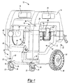
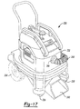
- FIG. 1 is a front perspective view of an exemplary wet/dry vacuum constructed in accordance with the teachings of the present disclosure;
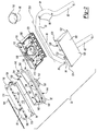
- FIG. 2 is an exploded perspective view of a floor collector assembly and mounting bar of the wet/dry vacuum of FIG. 1;
- FIG. 3 is a front perspective view of a portion of the vacuum of FIG. 1 including a floor scoop and connecting duct shown in a first (or sweep) mode of operation;
- FIG. 4 is a side view of a portion of the vacuum shown in FIG. 3;
- FIG. 5 is a sectional view of the floor scoop and connecting duct in the first mode taken along line 5-5 of FIG. 3;
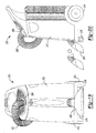
- FIG. 6 is an action sequence illustrating rotation of the floor scoop relative to the connecting duct;
- FIG. 7 is a detail view of a hub disposed on the floor scoop in a nested between cooperating fingers of the connecting duct in an engaged position;
- FIG. 8 is a detail view of the hub of the floor scoop in an unengaged position relative to cooperating fingers disposed on the connecting duct;
- FIG. 9 is a front perspective view of a portion of the vacuum of FIG. 1 including a floor scoop and connecting duct shown in a second (or floor nozzle) mode of operation;
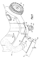
- FIG. 10 is a side view of a portion of the vacuum shown in FIG. 9;
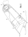
- FIG. 11 is a sectional view of the floor scoop and connecting duct in the second mode taken along line 11-11 of FIG. 9;
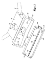
- FIG. 12 is a front perspective view of the floor connecting assembly of the vacuum in FIG. 1 and illustrating a squeegee attachment offset from the floor scoop;
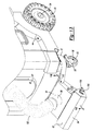
- FIG. 13 is a front perspective view of a portion of the vacuum of FIG. 1 shown with the squeegee attachment connected to the floor scoop in a third (or squeegee) mode of operation;
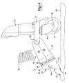
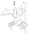
- FIG. 14 is a side view of a portion of the vacuum shown in FIG. 13 (solid line) and also shown with the floor collector assembly rotated about an axis of the mounting bar in a storage position (phantom line);
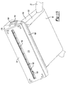
- FIG. 15 is a bottom perspective view of the floor collector assembly with the squeegee attachment coupled to the floor scoop in the third mode; and
- FIG. 16 is a sectional view of the floor collector assembly in the third mode taken along line 16-16 of FIG. 13.
- With initial reference to FIG. 1, an exemplary vacuum constructed in accordance with the present teachings is shown and generally identified at
reference numeral 10. Thevacuum 10 can generally include ahousing 12, acover 14, amotor assembly 16, and afloor collector assembly 20. Thefloor collector assembly 20 can be rotatably coupled to amounting bar 22 extending from thehousing 12. Themotor assembly 16 can be disposed within thehousing 12 and/or thecover 14. Themotor assembly 16 can include amotor 26 that drives an impeller (fan) 28 through anoutput shaft 30. Themotor 26 can be powered by an AC source by way of anelectrical plug 32. An on/off switch (not shown) may be provided on thehousing 12 orcover 14. Aninlet 34 can be defined on thehousing 12. Anintake port 36 can be integrally formed or otherwise coupled to thehousing 12 at theinlet 34. During operation of thevacuum 10, rotation of theimpeller 28 can cause suction within thehousing 10 for ingesting debris and/or liquid through theinlet 34. Exhausted air may exit thehousing 12 at an outlet port (not specifically shown). - The
exemplary vacuum 10 can define a cube-like shape having opposing front andrear sides 40 and 42 connected between opposing connectingsides vacuum 10 for rolling thevacuum 10 across a floor. The first pair of wheels 48 (only one shown) may be fixed for rotation about anaxle 54 that defines an axis generally parallel to the front andrear sides 40 and 42. The second pair ofwheels 50 can be caster wheels that rotate about axles withinrespective carriers 58. Thecarriers 58 can be coupled to the mountingbar 22 for rotation aboutrespective axes 60. Other wheel configurations may be employed. - A pair of latches 62 (only one shown) can be disposed on the opposing
sides vacuum 10. Description of the exposedlatch 62 on the opposingside 44 will now be described while it is appreciated that the same latch configuration may be provided on the other opposingside 46. Thelatch 62 can generally define a mountingbore 64 on a first end and acurved retaining portion 66 on a second end. Thelatch 62 can be mounted about ashaft 68 extending in apocket 70 defined on the opposingside 44. Thelatch 62 can rotate about theshaft 68 between a secured position (solid line, FIG. 1) wherein thecurved retaining portion 66 captures aledge 74 of thecover 14, and an unsecured position (phantom line, FIG. 1). In the unsecured position, thecover 14 can be lifted (i.e. in a direction upward as viewed in FIG. 1) away from thehousing 12 for accessing themotor assembly 16 and/or emptying the vacuumed contents from thehousing 12. Thecover 14 can define a pair ofhandles 76 formed thereon. An operator can grasp thehandles 76 to move thevacuum 10 as a whole or lift thecover 14 away from thehousing 12. - With continued reference to FIG. 1 and additional reference to FIGS. 2 and 3, the mounting
bar 22 andfloor collection assembly 20 will be described in greater detail. The mountingbar 22 can define a tubular member having a linearcentral portion 80, a pair oflinear end portions 82, and a pair ofcurved portions 84 that transition between the linearcentral portion 80 and thelinear end portions 82.Apertures 86 can be formed through the mountingbar 22 for receiving fasteners (not shown) to couple to mountingbar 22 to thehousing 12. - The
floor collection assembly 20 can include a connecting duct 90 (FIG. 1), afloor scoop 92, asqueegee adapter 94, and a hose cuff 96 (FIG. 2). The connectingduct 90 can be collectively defined by a first and asecond clamshell portion 100 and 102 (FIG. 2), respectively. Thefirst clamshell portion 100 can define a mountingsleeve 104 and a firstsemi-hemispherical wall portion 106. The mountingsleeve 104 can be adapted to receive thehose cuff 96.First fingers 110 can be formed on aforward face 112 of thefirst clamshell portion 100. A firstannular lip 116 can be formed on the mountingsleeve 104 for cooperatively mating with a secondannular lip 118 formed on thehose cuff 96. A first half-cylinder 120 can be defined on thefirst clamshell portion 100. A secondsemi-hemispherical wall portion 122 can be defined on thesecond clamshell portion 102.Second fingers 124 can be formed on aforward face 126 of thesecond clamshell portion 102. - The connecting
duct 90 can generally define a first and a second pair of opposingsides bore 136 can be collectively defined by the first and secondsemi-hemispherical wall portions cylinders central portion 80 of the mountingbar 22 in the assembled position. The connectingduct 90 can be formed of durable lightweight material such as plastic. - Returning now to FIG. 2, the
floor scoop 92 can generally define a first pair of opposingsurfaces surfaces back surface 150, and acollar 152. Anopening 154 is defined collectively by the opposingsurfaces back surface 150 and thecollar 152 can cooperate to define achute 156. Thefirst surface 142 of the first pair of opposingsurfaces second surface 144 of the first pair of opposingsurfaces opening 154 can define an acute angle β (FIG. 4) relative to theback surface 150. Thefirst surface 142 can define afirst sweep edge 158. Thesecond surface 144 can define asecond sweep edge 160. Thecollar 152 can be generally cylindrical and extend from theback surface 150. Anannular ring 162 can be integrally formed around thecollar 152. A pair oftabs 164 can be formed on the second pair of opposingsurfaces back surface 150 can define a pair of hubs 166 (best shown in FIG. 6). Thefloor scoop 92 can be formed of durable lightweight material such as plastic. - With continued reference to FIG. 2, the
squeegee adapter 94 can define abottom surface 170, a forward surface 172 and a pair of side surfaces 174 and 176. Alongitudinal opening 180 can be formed through thebottom surface 170. A plurality of connectingpins 182 can be formed on thesqueegee adapter 94 adjacent to thelongitudinal opening 180. In one example, the connecting pins can define Christmas tree retainers although other configurations or arrangements are contemplated. Ablade 184 can define a complementary plurality ofpassages 186 for accepting the connectingpins 182 in an installed position (see also FIG. 16). Theblade 184 can define a linear body that substantially corresponds for accommodation by thelongitudinal opening 180. A pair ofears 184 can be formed on the pair of side surfaces 176 and 178, respectively. Aflap 188 can be formed along thebottom surface 170 of thesqueegee adapter 94. Thesqueegee adapter 94 can be formed of a durable lightweight material such as plastic while theblade 184 can be formed of resilient material such as rubber. - With reference now to all FIGS., the
vacuum 10 according to the present teachings is operable in a plurality of operating modes. More specifically, thefloor collector assembly 20 can be manipulated into multiple shapes and orientations to accommodate a given task. The various modes can include a first or "sweep mode" (FIGS. 3-5), a second or "floor nozzle mode" (FIGS. 9-11), and a third or "squeegee mode" (FIGS. 13-16). Thevacuum 10 can also operate in a fourth mode wherein a connectinghose 192 coupled between theintake port 36 and thehose cuff 96 of thefloor collector assembly 20 is disconnected from thehose cuff 96 and used as a conventional vacuum hose. In the fourth mode, thefloor collection assembly 20 can be rotated about the mountingbar 22 to a transportation position (FIG. 1). - With particular reference now to FIGS. 3-5, operation of the
vacuum 10 in the "sweep mode" will be described in greater detail. In the "sweep mode", the connectingduct 90 is rotated about anaxis 200 defined by the mountingbar 22 such that thefirst sweep edge 158 slides against or substantially adjacent to a vacuumedsurface 202. The connectinghose 192 can be coupled between theintake port 36 and thehose cuff 96. In this position, theopening 154 of thefloor scoop 92 can define an angle α1 relative to the vacuumedsurface 202. The angle α1 can be substantially about 90 degrees. It is appreciated that this angle can be altered by rotating the connectingduct 90 about the mountingbar axis 200. The annular ring 162 (FIG. 5) of thefloor scoop 92 can nest within anannular pocket 206 defined inboard of the first and secondsemi-hemispherical wall portions 106 on the connectingduct 90. In the "sweep mode," thefloor scoop 92, the connectingduct 90 and the connectinghose 192 each act as sequential debris-passing ducts to direct the vacuumed material into thehousing 12. - With continued reference to FIG. 5 and additional reference to FIGS. 6-8, movement of the
floor scoop 92 relative to the connectingduct 90 will be described. In general, the collar 152 (FIGS. 2 and 5) can selectively rotate about an axis 210 (FIG. 5) defined by the mountingbore 136 of the connectingduct 90. During rotation, theannular ring 162 of thefloor scoop 92 can ride within theannular pocket 206 of the connecting duct 90 (FIG. 5). As shown in FIG. 7, while in one of the modes (i.e., sweep mode, floor nozzle mode etc.), the hubs 166 (only one shown) of thefloor scoop 92 positively nest in a locked position within anotch 212 defined between thefingers duct 90. Upon enough rotational force F (FIG. 8) administered by a user onto thefloor scoop 92, thehub 166 can ramp out of thenotch 212 over one of thefingers floor scoop 92 about the axis 210). - With particular reference now to FIGS. 9-11, operation of the vacuum in the "floor nozzle mode" will be described in greater detail. In the "floor nozzle mode", the connecting
duct 90 is rotated about the mounting bar 22 (e.g., about theaxis 200, FIG. 10) such that thesecond sweep edge 160 slides against or substantially adjacent a vacuumedsurface 202. As can be appreciated from the preceding discussion, thefloor scoop 92 can rotate 180 degrees about the axis 210 (FIG. 6) from the "sweep mode" position to the "floor nozzle mode", and vice-versa. The connectinghose 192 can be coupled between the intake port 36 (FIG. 1) and thehose cuff 96. In this position, theopening 154 of thefloor scoop 92 can define an angle α2 (FIG. 10) relative to the vacuumedsurface 202. The angle α2 can be an acute angle. In one example, the angle α2 can be approximately between 25 and 65 degrees. It is appreciated that this angle can be altered by rotating the connectingduct 90 about the mountingbar axis 200. In the "floor nozzle mode," thefloor scoop 92, the connectingduct 90 and the connectinghose 192 each act as sequential debris-passing ducts to direct the vacuumed material into thehousing 12. - With particular reference now to FIGS. 12-16, operation of the
vacuum 10 in the "squeegee mode" will be described in greater detail. In the squeegee mode, thesqueegee adapter 94 is coupled to thefloor scoop 92. More specifically, theflap 188 of thesqueegee adapter 94 can be located against thefirst wall 144 of thefloor scoop 92. As best illustrated in FIG. 16, a locatingridge 214 defined on theflap 188 can nest within agroove 216 defined on thewall 144 of thefloor scoop 92. Theears 184 of thesqueegee attachment 94 can ramp over therespective tabs 164 of thefloor scoop 92 until they reach a position beyond the ramps 164 (FIG. 13). In the squeegee mode, thebottom surface 170 can be substantially parallel to the vacuumed surface 202 (FIG. 14). Again, It is appreciated that this angle can be altered by rotating the connectingduct 90 about the mountingbar axis 200. Theblade 184 can extend through thelongitudinal passage 180 for slidably traversing along the vacuumedsurface 202. As can be appreciated, theblade 184 can assist in directing liquid (and/or solid debris) to a position near thelongitudinal passage 180 to be siphoned. In the "squeegee mode", thesqueegee adapter 94, thefloor scoop 92, the connectingduct 90 and the connectinghose 192 each act as sequential debris-passing ducts to direct the vacuumed material into thehousing 12. - While the invention has been described in the specification and illustrated in the drawings with reference to various embodiments, it will be understood by those skilled in the art that various changes may be made and equivalents may be substituted for elements thereof without departing from the scope of the invention as defined in the claims. Furthermore, the mixing and matching of features, elements and/or functions between various embodiments is expressly contemplated herein so that one of ordinary skill in the art would appreciate from this disclosure that features, elements and/or functions of one embodiment may be incorporated into another embodiment as appropriate, unless described otherwise above. Moreover, many modifications may be made to adapt a particular situation or material to the teachings of the invention without departing from the essential scope thereof. Therefore, it is intended that the invention not be limited to the particular embodiment illustrated by the drawings and described in the specification as the best mode presently contemplated for carrying out this invention, but that the invention will include any embodiments falling within the foregoing description and the appended claims.
Claims (23)
- A vacuum comprising:a housing having an inlet adapted to receive debris being vacuumed;a mounting member fixedly coupled to the housing;a floor collector assembly rotatably disposed about a first axis defined by the mounting member, the floor collector assembly including a connecting duct and a floor scoop that defines an opening; andwherein the floor scoop rotates relative to the connecting duct about a second axis between a first position and a second position, wherein the opening is at a first orientation relative to a vacuumed surface in the first position and at a second orientation relative to the vacuumed surface in the second position, wherein the first orientation is distinct from the second orientation and wherein the first axis intersects the second axis.
- The vacuum of claim 1 wherein the opening defines a plane that is substantially perpendicular to the vacuumed surface in the first position and defines an acute angle relative to the vacuumed surface in the second position.
- The vacuum of claim 1 wherein the mounting member comprises a tubular bar and wherein the floor collector assembly is rotatable about the tubular bar into a storage position wherein the floor collector assembly is offset from a ground surface.
- The vacuum of claim 1 wherein one of the floor scoop or the connecting duct defines a collar and the other of the floor scoop or the connecting duct defines a bore, wherein the collar rotates within the bore about the second axis during rotation of the floor scoop between the first position and the second position.
- The vacuum of claim 4 wherein one of the floor scoop or the connecting duct defines a hub and the other of the floor scoop or the connecting duct has a pair of fingers that define a notch, wherein the hub positively nests in the notch in the first and second positions and wherein the hub ramps out of the notch over one of the fingers upon sufficient force during movement of the floor scoop from the first or second positions.
- The vacuum of claim 2, further comprising an attachment selectively coupled to the floor scoop in an installed position, the attachment defining a longitudinal passage that defines a substantially smaller area than the opening, wherein the longitudinal passage defines a plane that is substantially parallel to the vacuumed surface in the installed position.
- The vacuum of claim 6 wherein the attachment includes a blade that extends through the longitudinal passage and is adapted to slidably traverse along the vacuumed surface.
- A vacuum comprising:a housing having an inlet adapted to receive debris being vacuumed;a mounting bar fixedly coupled to the housing;a floor collector assembly rotatably disposed about a first axis defined by the mounting bar, the floor collector assembly including a first debris-passing member coupled to the mounting bar, a second debris-passing member rotatably coupled to the first debris-passing member and defining an opening, and a third debris-passing member removably coupled to the second debris-passing member; andwherein the floor collector assembly is operable in a plurality of modes comprising:a first mode wherein the opening is substantially perpendicular relative to a vacuumed surface;a second mode wherein the second debris-passing member is rotated relative to the first debris-passing member about a second axis such that the opening is at an acute angle relative to the vacuumed surface; anda third mode wherein the third debris-passing member is coupled to the second debris-passing member wherein a passage defined through the third debris-passing member is substantially parallel to the vacuumed surface.
- The vacuum of claim 8 wherein the first axis intersects the second axis.
- The vacuum of claim 9 wherein the first axis is substantially perpendicular to the second axis.
- The vacuum of claim 8 wherein one of the first or second debris-passing members defines a collar and the other of the first or second debris-passing members defines a bore, wherein the collar rotates within the bore about the second axis during rotation of the second debris-passing member relative to the first debris-passing member.
- The vacuum of claim 11 wherein one of the first or second debris-passing members defines a hub and the other of the first or second debris-passing members has a pair of fingers that define a notch, wherein the hub positively nests in the notch in a first position at the first mode and wherein the hub ramps out of the notch over one of the fingers upon sufficient force during movement of the second debris-passing member out of the first position.
- The vacuum of claim 8 wherein the first debris-passing member defines opposing clam-shell portions that cooperate to form a first and a second pair of opposing planar sides.
- The vacuum of claim 13 wherein the second debris-passing member defines a back surface and a first pair of opposing surfaces, wherein one surface of the first pair of opposing surfaces is larger than the corresponding opposing surface of the first pair such that the opening defines an acute angle relative to the back surface.
- The vacuum of claim 14 wherein the back surface opposes the first debris-passing member.
- A vacuum comprising:a housing having an inlet adapted to receive debris being vacuumed;a mounting bar coupled to the housing;a floor collector assembly rotatably disposed about a first axis defined by the mounting bar, the floor collector assembly including a first debris-passing member coupled to the mounting bar, a second debris-passing member rotatably coupled to the first debris-passing member and defining an opening, and a third debris-passing member removably coupled to the second debris-passing member; andwherein the floor collector assembly is operable in a plurality of modes comprising:a first mode wherein the opening is at a first orientation relative to a vacuumed surface;a second mode wherein the second debris-passing member is rotated relative to the first debris-passing member about a second axis such that the opening is at a second orientation relative to the vacuumed surface; anda third mode wherein the third debris-passing member is coupled to the second debris-passing member at the second orientation wherein a passage defined through the third debris-passing member is substantially parallel to the vacuumed surface.
- The vacuum of claim 16 wherein the first axis is substantially perpendicular to the second axis.
- The vacuum of claim 16 wherein one of the first or second debris-passing members defines a collar and the other of the first or second debris-passing members defines a bore, wherein the collar rotates within the bore about the second axis during rotation of the second debris-passing member relative to the first debris-passing member.
- The vacuum of claim 16 wherein one of the first or second debris-passing members defines a hub and the other of the first or second debris-passing members has a pair of fingers that define a notch, wherein the hub positively nests in the notch in a first position at the first mode and wherein the hub ramps out of the notch over one of the fingers upon sufficient force during movement of the second debris-passing member out of the first position.
- The vacuum of claim 16 wherein the first debris passing member defines opposing claim-shell portions that cooperate to form a first and a second pair of opposing planar sides.
- The vacuum of claim 20 wherein the second debris-passing member defines a back surface and a first pair of opposing surfaces, wherein one surface of the first pair of opposing surfaces is larger than the corresponding opposing surface of the first pair such that the opening defines an acute angle relative to the back surface.
- The vacuum of claim 21 wherein the back surface opposes the first debris-passing member.
- A vacuum comprising:a housing having an inlet adapted to receive debris being vacuumed;a mounting bar fixedly coupled to the housing;a floor collector assembly rotatably disposed about a first axis defined by the mounting bar, the floor collector assembly including a first debris-passing member coupled to the mounting bar, a second debris-passing member rotatably coupled to the first debris-passing member and having a substantially rectangular footprint defining an opening, and a third debris-passing member removably coupled to the second debris-passing member; andwherein the floor collector assembly is operable in a plurality of modes comprising:a first mode wherein the opening is substantially perpendicular relative to a vacuumed surface;a second mode wherein the second debris-passing member is rotated relative to the first debris-passing member about a second axis defined by a cooperating collar and bore formed on the first and second debris-passing members, respectively, such that the opening is at an acute angle relative to the vacuumed surface, the second axis being substantially perpendicular to the first axis; anda third mode wherein the third debris-passing member is coupled to the second debris-passing member wherein a passage defined through the third debris-passing member is substantially parallel to the vacuumed surface.
Applications Claiming Priority (2)
| Application Number | Priority Date | Filing Date | Title |
|---|---|---|---|
| US85994606P | 2006-11-20 | 2006-11-20 | |
| US11/870,986 US7877839B2 (en) | 2006-11-20 | 2007-10-11 | Wet and/or dry vacuum with floor collector |
Publications (2)
| Publication Number | Publication Date |
|---|---|
| EP1929913A1 true EP1929913A1 (en) | 2008-06-11 |
| EP1929913B1 EP1929913B1 (en) | 2012-02-22 |
Family
ID=38951279
Family Applications (1)
| Application Number | Title | Priority Date | Filing Date |
|---|---|---|---|
| EP07121045A Not-in-force EP1929913B1 (en) | 2006-11-20 | 2007-11-19 | Wet and/or dry vacuum cleaner with nozzle assembly |
Country Status (2)
| Country | Link |
|---|---|
| US (3) | US7877839B2 (en) |
| EP (1) | EP1929913B1 (en) |
Cited By (2)
| Publication number | Priority date | Publication date | Assignee | Title |
|---|---|---|---|---|
| WO2014201241A1 (en) * | 2013-06-14 | 2014-12-18 | Tennant Company | Surface maintenance vehicle with self-cleaning reservoir that captures hose runoff |
| US10188251B2 (en) | 2014-11-03 | 2019-01-29 | Tennant Company | Surface maintenance vehicle with an integrated water trap for trapping residual waste |
Families Citing this family (18)
| Publication number | Priority date | Publication date | Assignee | Title |
|---|---|---|---|---|
| SE533279C2 (en) * | 2008-12-22 | 2010-08-10 | Signe Grassman | Nozzle |
| USD657101S1 (en) | 2010-10-21 | 2012-04-03 | Emerson Electric Co. | Combined wet/dry vacuum cleaner with a detachable blower and accessory storage |
| USD647261S1 (en) | 2010-11-16 | 2011-10-18 | Emerson Electric Co. | Combined wet/dry vacuum cleaner with onboard tool storage and integrated dustpan accessory |
| US20120246866A1 (en) * | 2011-03-28 | 2012-10-04 | Emerson Electric Co. | Support System Adjustable by Like Motion and Method of Use |
| US20120311815A1 (en) * | 2011-06-13 | 2012-12-13 | Abraham Martin Pickens | Collapsible Detail Attachment For Use With Public Vacuum Cleaners |
| US9282861B2 (en) | 2011-10-18 | 2016-03-15 | Emerson Electric Co. | Wet/dry vacuum cleaner with built-in dustpan accessory |
| EP2661165A1 (en) * | 2012-05-02 | 2013-11-06 | ABB Research Ltd. | Cooling assembly |
| US8997308B2 (en) | 2012-07-24 | 2015-04-07 | Koblenz Electricia S.A. de C.V. | Wet/dry vacuum cleaner |
| USD749805S1 (en) | 2013-10-08 | 2016-02-16 | Briggs & Stratton Corporation | Pressure washer |
| USD727847S1 (en) | 2013-10-08 | 2015-04-28 | Briggs & Stratton Corporation | Portable generator |
| USD742080S1 (en) * | 2013-10-16 | 2015-10-27 | Briggs & Stratton Corporation | Pressure washer |
| US11076733B2 (en) | 2017-01-06 | 2021-08-03 | Dynamic Concrete, Llc | Method and apparatus for attaching a floor tool to a vacuum frame |
| USD912342S1 (en) * | 2019-03-04 | 2021-03-02 | Black & Decker Inc. | Vacuum |
| US12349857B2 (en) * | 2021-02-25 | 2025-07-08 | Techtronic Cordless Gp | Dustpan accessory tool for vacuum cleaner |
| CA3157034A1 (en) * | 2021-05-03 | 2022-11-03 | Techtronic Cordless Gp | Dustpan accessory tool for vacuum cleaner |
| USD1091990S1 (en) * | 2021-11-05 | 2025-09-02 | Festool Gmbh | Vacuum cleaner |
| US11786089B2 (en) * | 2022-01-13 | 2023-10-17 | Emerson Electric Co. | Vacuum cleaner including hose retainer with dustpan and method of assembling same |
| TWD231721S (en) * | 2023-04-19 | 2024-06-11 | 大陸商北京石頭世紀科技股份有限公司 (中國大陸) | Storage bracket for accessories of cleaning appliance |
Citations (6)
| Publication number | Priority date | Publication date | Assignee | Title |
|---|---|---|---|---|
| WO1992018045A1 (en) * | 1991-04-11 | 1992-10-29 | Allan Furendal | Devices for vacuum cleaner |
| EP1110496A1 (en) * | 1999-12-24 | 2001-06-27 | Wessel-Werk Gmbh | Floor nozzle for vacuum cleaner |
| DE20106784U1 (en) * | 2001-04-19 | 2001-07-19 | BSH Bosch und Siemens Hausgeräte GmbH, 81669 München | vacuum cleaner |
| US20020108209A1 (en) * | 2001-02-12 | 2002-08-15 | Peterson Robert A. | Wet vacuum |
| GB2398735A (en) * | 2003-01-03 | 2004-09-01 | Matsushita Electric Corp | A floor cleaning device with a pivotally mounted agitator section |
| DE202005006188U1 (en) * | 2005-04-18 | 2005-09-15 | Afrasiabi Anna Maria | Mobile industrial vacuum cleaner, has suction hose for wet and dry suction, and lever for raising or lowering suction beam |
Family Cites Families (38)
| Publication number | Priority date | Publication date | Assignee | Title |
|---|---|---|---|---|
| CH442643A (en) | 1966-01-26 | 1967-08-31 | Hitachi Ltd | vacuum cleaner |
| US3634904A (en) * | 1969-11-20 | 1972-01-18 | Wayne Manufacturing Co | Road sweeper suction and dirt chamber connection |
| DE1964261C3 (en) * | 1969-12-22 | 1973-06-28 | Matsushita Electric Ind Co Ltd | Electric motor driven vacuum cleaner |
| US3708962A (en) * | 1970-03-20 | 1973-01-09 | Sanyo Electric Co | Vacuum cleaner |
| US3813725A (en) * | 1972-08-17 | 1974-06-04 | Atwater Strong Co Inc | Vacuum cleaner construction |
| US4345353A (en) * | 1979-07-23 | 1982-08-24 | Tennant Company | Filtering device |
| US4258451A (en) * | 1979-07-23 | 1981-03-31 | Tennant Company | Surface sweeping machine |
| US4360947A (en) * | 1980-10-30 | 1982-11-30 | Decosa Charles | Dust collector |
| US4328014A (en) * | 1981-04-22 | 1982-05-04 | The Scott & Fetzer Company | Sweeper hopper with filter assembly |
| US4660248A (en) * | 1984-09-12 | 1987-04-28 | Tymco, Inc. | Pickup truck mounted sweeper |
| US4704144A (en) * | 1986-02-24 | 1987-11-03 | Donaldson Company, Inc. | Air filtering apparatus |
| US4787923A (en) * | 1986-08-27 | 1988-11-29 | Tennant Company | Apparatus for cleaning an air filter |
| US4833752A (en) * | 1988-08-08 | 1989-05-30 | Merrick John T | Vacuum mop head |
| JP2850409B2 (en) | 1989-11-01 | 1999-01-27 | 株式会社豊田自動織機製作所 | Filter dust removal equipment for floor cleaning vehicles |
| US5013333A (en) * | 1990-04-13 | 1991-05-07 | Tennant Company | Unattended air cleaning system for surface maintenance machine |
| DE4138223C1 (en) | 1991-11-21 | 1993-02-18 | Alfred Kaercher Gmbh & Co, 7057 Winnenden, De | Vacuum cleaner with cleaning unit for filter - has separate filters closing through holes in parallel between dust collector and suction unit |
| CA2087474C (en) * | 1993-01-18 | 1996-09-10 | J. A. Denis Courcelles | Dust pan for use with a vacuum |
| DE4304681C2 (en) * | 1993-02-16 | 1996-06-05 | Wessel Werk Gmbh | One-piece vacuum cleaner nozzle |
| DE4332405A1 (en) | 1993-09-23 | 1995-03-30 | Ruwac Industriesauger Gmbh | Filter, in particular for industrial vacuum equipment |
| US5839157A (en) * | 1996-05-06 | 1998-11-24 | Elgin Sweeper Company | Street sweeper pick-up head |
| JP3632370B2 (en) | 1997-05-08 | 2005-03-23 | 株式会社豊田自動織機 | Filter dust remover for floor cleaning vehicles |
| US5983442A (en) * | 1997-06-06 | 1999-11-16 | The Hoover Company | Carpet extractor with automatic conversion |
| US5953788A (en) * | 1998-03-26 | 1999-09-21 | Douglas; Stephen W. | Electric dust pan |
| JP4438205B2 (en) | 2000-09-25 | 2010-03-24 | 豊和工業株式会社 | Filter device for cleaning machine |
| US6671924B1 (en) * | 2000-12-12 | 2004-01-06 | Richard K. Rood | Vacuum dustpan |
| GB2377880A (en) * | 2001-07-25 | 2003-01-29 | Black & Decker Inc | Multi-operational battery powered vacuum cleaner |
| DE10143941A1 (en) | 2001-09-07 | 2003-03-27 | Hako Gmbh | Process for cleaning the filter of a mobile floor cleaning machine and mobile floor cleaning machine |
| US6895632B2 (en) * | 2002-06-19 | 2005-05-24 | Black & Decker Inc. | Hand held vacuum with arcuate gliding surface |
| DE10231391A1 (en) * | 2002-07-08 | 2004-02-12 | Alfred Kärcher Gmbh & Co. Kg | Tillage system |
| DE10231388A1 (en) * | 2002-07-08 | 2004-02-05 | Alfred Kärcher Gmbh & Co. Kg | Tillage system |
| US6966097B2 (en) * | 2002-09-06 | 2005-11-22 | Tennant Company | Street sweeper with dust control |
| JP2004121621A (en) | 2002-10-04 | 2004-04-22 | Toshiba Tec Corp | Electric vacuum cleaner |
| JP3970154B2 (en) * | 2002-10-28 | 2007-09-05 | 三洋電機株式会社 | Floor suction tool |
| JP4189809B2 (en) | 2003-08-20 | 2008-12-03 | 豊和工業株式会社 | Dust removal device in filter device of garbage truck |
| US7171719B1 (en) * | 2004-07-27 | 2007-02-06 | David Harrelson | Disposal apparatus |
| KR100729716B1 (en) | 2005-10-19 | 2007-06-19 | 삼성광주전자 주식회사 | Vacuum cleaner |
| JP2007319352A (en) | 2006-05-31 | 2007-12-13 | Toshiba Corp | Electric vacuum cleaner |
| US8015657B2 (en) | 2007-02-09 | 2011-09-13 | Black & Decker Inc. | Vacuum electronic power tool sense |
-
2007
- 2007-10-11 US US11/870,986 patent/US7877839B2/en not_active Expired - Fee Related
- 2007-11-16 US US11/941,471 patent/US8627538B2/en not_active Expired - Fee Related
- 2007-11-19 EP EP07121045A patent/EP1929913B1/en not_active Not-in-force
-
2011
- 2011-01-04 US US12/984,228 patent/US8037570B2/en not_active Expired - Fee Related
Patent Citations (6)
| Publication number | Priority date | Publication date | Assignee | Title |
|---|---|---|---|---|
| WO1992018045A1 (en) * | 1991-04-11 | 1992-10-29 | Allan Furendal | Devices for vacuum cleaner |
| EP1110496A1 (en) * | 1999-12-24 | 2001-06-27 | Wessel-Werk Gmbh | Floor nozzle for vacuum cleaner |
| US20020108209A1 (en) * | 2001-02-12 | 2002-08-15 | Peterson Robert A. | Wet vacuum |
| DE20106784U1 (en) * | 2001-04-19 | 2001-07-19 | BSH Bosch und Siemens Hausgeräte GmbH, 81669 München | vacuum cleaner |
| GB2398735A (en) * | 2003-01-03 | 2004-09-01 | Matsushita Electric Corp | A floor cleaning device with a pivotally mounted agitator section |
| DE202005006188U1 (en) * | 2005-04-18 | 2005-09-15 | Afrasiabi Anna Maria | Mobile industrial vacuum cleaner, has suction hose for wet and dry suction, and lever for raising or lowering suction beam |
Cited By (4)
| Publication number | Priority date | Publication date | Assignee | Title |
|---|---|---|---|---|
| WO2014201241A1 (en) * | 2013-06-14 | 2014-12-18 | Tennant Company | Surface maintenance vehicle with self-cleaning reservoir that captures hose runoff |
| CN105451623A (en) * | 2013-06-14 | 2016-03-30 | 坦南特公司 | Surface maintenance vehicle with self-cleaning reservoir that captures hose runoff |
| US10368712B2 (en) | 2013-06-14 | 2019-08-06 | Tennant Company | Surface maintenance vehicle with self-cleaning reservoir that captures hose runoff |
| US10188251B2 (en) | 2014-11-03 | 2019-01-29 | Tennant Company | Surface maintenance vehicle with an integrated water trap for trapping residual waste |
Also Published As
| Publication number | Publication date |
|---|---|
| US20110094053A1 (en) | 2011-04-28 |
| EP1929913B1 (en) | 2012-02-22 |
| US20080115317A1 (en) | 2008-05-22 |
| US8037570B2 (en) | 2011-10-18 |
| US20080115307A1 (en) | 2008-05-22 |
| US8627538B2 (en) | 2014-01-14 |
| US7877839B2 (en) | 2011-02-01 |
Similar Documents
| Publication | Publication Date | Title |
|---|---|---|
| EP1929913B1 (en) | Wet and/or dry vacuum cleaner with nozzle assembly | |
| CN101410046B (en) | handheld vacuum cleaner | |
| KR100879081B1 (en) | Surface treatment mechanism | |
| CA2424742C (en) | Edge cleaning system for vacuum cleaner | |
| US20110308038A1 (en) | Vacuum cleaner | |
| US20210330161A1 (en) | Rotary working element | |
| US20030005546A1 (en) | Air flow modification in vacuum cleaners | |
| EP3030127B1 (en) | A nozzle for a vacuum cleaner | |
| US20250127355A1 (en) | Vacuum cleaner with enhanced backstroke pick-up | |
| GB2488405A (en) | A floor care apparatus | |
| KR100849778B1 (en) | Electric cleaner and suction mouth body | |
| US7594298B2 (en) | Duster having a rotatable vacuum pick-up | |
| CN110338710A (en) | Storage box, cleaning robot and cleaning system | |
| US20050022340A1 (en) | Nozzle assembly with high efficiency agitator cavity | |
| KR20100088354A (en) | A nozzle of vaccum cleaner | |
| CN211022468U (en) | Storage box, cleaning robot and cleaning system | |
| US20240415348A1 (en) | Swappable brushroll or cassette for vacuum cleaner | |
| US11382479B2 (en) | Floor cleaning machine | |
| KR0140763B1 (en) | Mop transfer device of vacuum cleaner | |
| JP2000000193A (en) | Portable dust collector | |
| JP3606437B2 (en) | Vacuum cleaner and its suction port | |
| KR20240020600A (en) | Vacuum cleaner | |
| KR200169070Y1 (en) | cleaning device for conner seat in up-right type vacuum cleaner | |
| KR100222651B1 (en) | Upright cleaner | |
| JP2001169978A (en) | Vacuum cleaner and its suction body |
Legal Events
| Date | Code | Title | Description |
|---|---|---|---|
| PUAI | Public reference made under article 153(3) epc to a published international application that has entered the european phase |
Free format text: ORIGINAL CODE: 0009012 |
|
| AK | Designated contracting states |
Kind code of ref document: A1 Designated state(s): AT BE BG CH CY CZ DE DK EE ES FI FR GB GR HU IE IS IT LI LT LU LV MC MT NL PL PT RO SE SI SK TR |
|
| AX | Request for extension of the european patent |
Extension state: AL BA HR MK RS |
|
| 17P | Request for examination filed |
Effective date: 20080708 |
|
| 17Q | First examination report despatched |
Effective date: 20080808 |
|
| AKX | Designation fees paid |
Designated state(s): DE FR GB |
|
| GRAP | Despatch of communication of intention to grant a patent |
Free format text: ORIGINAL CODE: EPIDOSNIGR1 |
|
| GRAJ | Information related to disapproval of communication of intention to grant by the applicant or resumption of examination proceedings by the epo deleted |
Free format text: ORIGINAL CODE: EPIDOSDIGR1 |
|
| GRAP | Despatch of communication of intention to grant a patent |
Free format text: ORIGINAL CODE: EPIDOSNIGR1 |
|
| GRAS | Grant fee paid |
Free format text: ORIGINAL CODE: EPIDOSNIGR3 |
|
| GRAA | (expected) grant |
Free format text: ORIGINAL CODE: 0009210 |
|
| AK | Designated contracting states |
Kind code of ref document: B1 Designated state(s): DE FR GB |
|
| REG | Reference to a national code |
Ref country code: GB Ref legal event code: FG4D |
|
| REG | Reference to a national code |
Ref country code: DE Ref legal event code: R096 Ref document number: 602007020814 Country of ref document: DE Effective date: 20120419 |
|
| PLBE | No opposition filed within time limit |
Free format text: ORIGINAL CODE: 0009261 |
|
| STAA | Information on the status of an ep patent application or granted ep patent |
Free format text: STATUS: NO OPPOSITION FILED WITHIN TIME LIMIT |
|
| 26N | No opposition filed |
Effective date: 20121123 |
|
| REG | Reference to a national code |
Ref country code: DE Ref legal event code: R097 Ref document number: 602007020814 Country of ref document: DE Effective date: 20121123 |
|
| REG | Reference to a national code |
Ref country code: FR Ref legal event code: ST Effective date: 20130731 |
|
| PG25 | Lapsed in a contracting state [announced via postgrant information from national office to epo] |
Ref country code: FR Free format text: LAPSE BECAUSE OF NON-PAYMENT OF DUE FEES Effective date: 20121130 |
|
| PGFP | Annual fee paid to national office [announced via postgrant information from national office to epo] |
Ref country code: GB Payment date: 20191115 Year of fee payment: 13 |
|
| PGFP | Annual fee paid to national office [announced via postgrant information from national office to epo] |
Ref country code: DE Payment date: 20201103 Year of fee payment: 14 |
|
| GBPC | Gb: european patent ceased through non-payment of renewal fee |
Effective date: 20201119 |
|
| PG25 | Lapsed in a contracting state [announced via postgrant information from national office to epo] |
Ref country code: GB Free format text: LAPSE BECAUSE OF NON-PAYMENT OF DUE FEES Effective date: 20201119 |
|
| REG | Reference to a national code |
Ref country code: DE Ref legal event code: R119 Ref document number: 602007020814 Country of ref document: DE |
|
| PG25 | Lapsed in a contracting state [announced via postgrant information from national office to epo] |
Ref country code: DE Free format text: LAPSE BECAUSE OF NON-PAYMENT OF DUE FEES Effective date: 20220601 |