EP1929354B1 - Energy signal processing system - Google Patents
Energy signal processing system Download PDFInfo
- Publication number
- EP1929354B1 EP1929354B1 EP06741171.0A EP06741171A EP1929354B1 EP 1929354 B1 EP1929354 B1 EP 1929354B1 EP 06741171 A EP06741171 A EP 06741171A EP 1929354 B1 EP1929354 B1 EP 1929354B1
- Authority
- EP
- European Patent Office
- Prior art keywords
- signal processing
- energy signal
- axis
- processing system
- shaft assembly
- Prior art date
- Legal status (The legal status is an assumption and is not a legal conclusion. Google has not performed a legal analysis and makes no representation as to the accuracy of the status listed.)
- Active
Links
Images
Classifications
-
- G—PHYSICS
- G01—MEASURING; TESTING
- G01S—RADIO DIRECTION-FINDING; RADIO NAVIGATION; DETERMINING DISTANCE OR VELOCITY BY USE OF RADIO WAVES; LOCATING OR PRESENCE-DETECTING BY USE OF THE REFLECTION OR RERADIATION OF RADIO WAVES; ANALOGOUS ARRANGEMENTS USING OTHER WAVES
- G01S7/00—Details of systems according to groups G01S13/00, G01S15/00, G01S17/00
- G01S7/48—Details of systems according to groups G01S13/00, G01S15/00, G01S17/00 of systems according to group G01S17/00
- G01S7/481—Constructional features, e.g. arrangements of optical elements
- G01S7/4811—Constructional features, e.g. arrangements of optical elements common to transmitter and receiver
-
- G—PHYSICS
- G02—OPTICS
- G02B—OPTICAL ELEMENTS, SYSTEMS OR APPARATUS
- G02B27/00—Optical systems or apparatus not provided for by any of the groups G02B1/00 - G02B26/00, G02B30/00
- G02B27/64—Imaging systems using optical elements for stabilisation of the lateral and angular position of the image
- G02B27/644—Imaging systems using optical elements for stabilisation of the lateral and angular position of the image compensating for large deviations, e.g. maintaining a fixed line of sight while a vehicle on which the system is mounted changes course
-
- G—PHYSICS
- G02—OPTICS
- G02B—OPTICAL ELEMENTS, SYSTEMS OR APPARATUS
- G02B7/00—Mountings, adjusting means, or light-tight connections, for optical elements
- G02B7/18—Mountings, adjusting means, or light-tight connections, for optical elements for prisms; for mirrors
- G02B7/182—Mountings, adjusting means, or light-tight connections, for optical elements for prisms; for mirrors for mirrors
- G02B7/1822—Mountings, adjusting means, or light-tight connections, for optical elements for prisms; for mirrors for mirrors comprising means for aligning the optical axis
- G02B7/1827—Motorised alignment
Definitions
- the present invention relates to an energy signal processing system for emitting and receiving energy signals.
- the invention has been developed primarily as a device for emitting, receiving and/or simply reflecting signals off an appropriate reflective surface. Thus, while the invention will be described hereinafter with reference to these applications, it will be appreciated that it is not limited to this particular field of use.
- Devices for emitting or receiving energy signals over a range of positions are known from the Japanese patent application JP2002168232 .
- One such device is the pan-tilt positioning device for a video camera.
- the energy signal being received is an optical video signal.
- this device includes two motor assemblies driving a video camera about a vertical and/or horizontal axis. In this way, video signals may be received over a range of positions based on selective rotation of the motors.
- a disadvantage of this device is its complexity and the amount of space required to package both motor assemblies.
- Another device that transmits an energy signal over a range of positions is the remote mirror module for a radar-emitting/receiving device.
- radio waves are emitted onto a reflective element which in turn is rotated about 360° to transmit the radio wave about this range. Returning radio waves are received and read along a reverse path.
- This device allows radar wave signals to be rotated about the 360° azimuth range whilst the emitting/receiving unit remains stationary.
- Many remote mirror module type devices are also capable of some zenith motion of the reflective element.
- a disadvantage of this arrangement is that the mechanism to rotate the mirror is required to be at opposite ends to the emitting/receiving unit.
- either the emitting/receiving unit or mirror rotation mechanism is exposed above the main support housing making it vulnerable to damage.
- having either the emitting/receiving unit or mirror rotation mechanism suspended above the other necessitates additional support structures, which may create occlusions in the transmission and/or reading path.
- the static array comprises a plurality of sensors disposed at various points around a frame, thereby to sense energy signals coming from various directions.
- the static array is not moveable, its sensing range is fixed.
- an energy signal processing system including the features of independent claim 1.
- said energy signal processing element is disposed on said azimuth axis and comprises a reflective element arranged to deflect energy signals, travelling substantially along said preselected path axis and impinging it, substantially along said azimuth axis and deflect energy signals travelling substantially along said azimuth axis and impinging it, substantially along said preselected path axis.
- said energy signal processing element comprises a sensor for sensing energy signals propagating substantially along said preselected path axis and impinging the energy signal processing element, or an energy signal source for generating energy signal/s.
- said energy signal processing element can comprise both a sensor for sensing energy signals propagating substantially along said preselected path axis and impinging energy signal processing element and an energy signal source for generating energy signal/s.
- said energy signal processing element is rotatably mounted to said second shaft assembly.
- said preselected path axis is parallel to said zenith plane.
- the second shaft assembly includes a zenith element constrained by the first shaft assembly for rotation about a scanning axis normal to the zenith plane. Furthermore, the rotation of the second shaft assembly with respect to the first shaft assembly, rotates the preselected path axis about the scanning axis.
- the energy signal deflector includes a transmission element rotatably mounted to the second shaft assembly for rotation about the processing element axis. Moreover, the zenith element is rotatably mounted to the transmission element for rotation about the preselected path axis.
- said transmission element includes a limiting aperture coaxially disposed with respect to said preselected path axis to define a predetermined angle of view of the energy signal processing element.
- said limiting aperture further comprises a protective planar window.
- said limiting aperture further comprises a focussing or collimating element for focussing or collimating an incoming and/or outgoing energy signal/s.
- said at least one collimating or focussing element is included intermediately said limiting aperture and said processing element.
- said first shaft assembly is substantially outboard of said second shaft assembly.
- the first shaft assembly is at least partially sleeved over the second shaft assembly.
- the means for rotating the reflective element includes at least one of a mechanical gear assembly, a mechanical linkage assembly, an electromechanical servo drive and an electronic system.
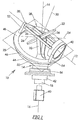
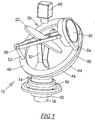
- an energy signal processing system 10 for emitting and/or receiving energy signals along a preselected path 12.
- the processing system includes an outer shaft assembly 14 mounted for rotation about an azimuth axis 16 and an inner shaft assembly 18 coaxially mounted for rotation about the same azimuth axis.
- the outer shaft assembly extends to define a zenith plane 20, which is inclined with respect to the azimuth axis. It should be understood that the definitions of "azimuth axis" or “zenith plane” only apply in a local frame of reference of the energy signal system. Accordingly, when in use, system 10 can be positioned in any orientation and under any angle with respect to globally defined “azimuth axis" or "zenith plane”.
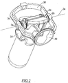
- the energy signal processing element in this preferred embodiment of system 10 is a reflective element 22, in the form of a mirror, that reflects energy signals emitted from an associated emitting means 60 or directs signals to an associated sensory means 60.
- reference 60 is used as a general reference to emitting/sensory means that may or may not be part of the energy processing system.
- Reflective element 22 intersects the azimuth axis 16 and is mounted to the inner shaft assembly 18 for rotation about processing element axis 24. To this end, the preselected path axis 12 extends parallel to the zenith plane and impinges on the reflective element.
- the reflective element 22 can be of any shape, material, structure or functionality that geometrically deflects the incoming or outgoing signals as appropriate for the particular application. It is clear that, instead to inner shaft assembly 18, reflective element 22 can be rotatably mounted to transmission element 38 which can then be mounted to the inner shaft assembly 18.
- a zenith element 28 is constrained by the outer shaft assembly 14 for rotation about a scanning axis 30, normal to the zenith plane 20.
- the inner shaft assembly which is rotatably mounted to the outer shaft assembly by a suitable bearing means (not shown), includes a generally hollow fork member 32 having a shaft 34 expending between its distal ends 36.
- a transmission element 38 is mounted to the shaft 34 for rotation about axis 24.
- the transmission element includes a focussing aperture 40 rotatably mounted to the zenith element 28 such that the aperture is maintained coaxial to the preselected path axis 12 whilst allowing the zenith element to freely rotate about the preselected path axis.
- the main purpose of aperture 40 is to limit the angle of view and, therefore, the amount of background noise reaching the sensing element, if the system is used to detect signals.
- the aperture also limits the spread of the output beam leaving the system, when the system is used as a scanning energy signal source. Of course, the system can be used to both receive and emit energy signals.
- aperture 40 can include just a planar protective window or even no window at all.
- Aperture 40 can also include collimating, instead of focussing optics. Focussing, collimating or other elements, can be also included at any intermediate point between the aperture and the energy signal processing element.
- the signal processing element is reflective element 22
- optical components can be, in fact, introduced anywhere between the aperture and the sensing/emitting means 60.
- a cover not shown, is used to cover the arrangement and protect it from the elements, as well as to further minimise the background noise.
- a gear assembly 26 rotatably drives the reflective element about axis 24 such that signals travelling from the focussing aperture 40 and along the preselected path axis 12 are deflected along the azimuth axis 16. Conversely, signals travelling along, or close to, the azimuth axis towards the reflective element are deflected along the preselected path axis to exit via the focussing aperture.
- the gear assembly 26 derives its input from rotation of the transmission element to rotate the reflective element 22 about axis 24. To this end, the gear assembly maintains the angle of projection of the reflective element such that signals entering along the preselected path 12 are reflected along the azimuth axis.
- the preselected path axis is parallel to the zenith plane.
- a system can be constructed such that the preselected path axis is inclined with respect to the zenith plane. Such a device would have the same zenith angle range, but this range would be asymmetrical about the horizontal.
- the gear assembly 26 may be replaced by other suitable arrangements such as a mechanical linkage; electromechanical servo system; electronic system or a combination thereof.
- the required motion of the reflective element 22 can also be achieved in a compound way using one of the aforementioned methods for gross motion and another for fine motion of all or part of, the reflective element.
- the outer shaft assembly 14 is in the form of a hollow shaft 42 that extends to define a generally hollow and generally spherically shaped body 44 having a circular and planar axially directed edge 46, which defines the zenith plane 20.
- the zenith element 28 includes a ring portion 48 having a circular and planar abutment surface 50 for sliding engagement between the zenith element and the outer shaft assembly.
- the zenith element further includes a pair of rotatable supports 52 and 54, each supporting a respective end of the transmission element 38.
- a base 56 which is rotatably connected to the outer shaft assembly, is provided for generally supporting the device 10.
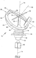
- the zenith plane is inclined at 45 degrees with respect to a plane perpendicular to the azimuth axis. Therefore, at the two extremes of rotation of the zenith element 28, the preselected path axis 12 may be inclined at a range of plus or minus 45 degrees with respect to a plane perpendicular to the azimuth axis 16.
- the angle of inclination of the zenith plane and the corresponding range of angles of inclination of the preselected path axis 12 with respect to a plane perpendicular to the azimuth axis may vary from 0 degrees to about 70 degrees, depending on the proposed application.
- the fork member 32 rotates the transmission element 38 about the azimuth axis 16.
- the zenith element is driven to rotate about the scanning axis 30 thereby in turn rotating the transmission element and preselected path axis 12 about axis 24.
- a sensory and/or emitting means 60 is disposed below system 10 for sensing signals entering the system and/or generating signals for outputting from the system.
- the means 60 can be in the form of a video camera and the energy signals are in the form of light or video signals. Accordingly, the video camera will be able to view anywhere within the full 360 degree azimuth range as well up and down the zenith range by selected rotation of the outer and inner shaft assemblies.
- the means 60 can be in the form of a radio wave emitter/receiver and the energy signals are radio waves, which travel along the azimuth axis to be deflected along the preselected path axis. Rebounding waves may then be received and interpreted via a reverse path. Accordingly, a continuous rotation of the deflector 10 can provide a continuous 360-degree radar scan, with variations along the zenith range as required.
- the system can also be used within a laser range finder arrangement.
- the disclosed system can be used for both passive applications, such as sensing signals using sensing elements or video cameras, or active applications, such as range finders or radars.
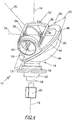
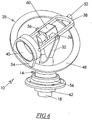
- sensor/emitting means 60 are housed within or below inner shaft assembly 18, they can also be mounted on the other side of reflective element 22, as shown in figure 5 .
- the reflective element is driven by similar means as in the preferred embodiment, such that the field of view of the sensor after being deflected by the reflective element is at all times aligned with the aperture. Since the signals do not have to pass through the inner shaft it is no longer necessary for it to be hollow.
- the sensor may be attached to the inner shaft to eliminate image rotation in array type sensors, or it can be isolated from the motion of the energy signal processing system.
- the energy signal processing system 10 illustrated by the preferred embodiment of the present invention allows the heavier, more fragile and relatively expensive working components to remain relatively stationary, thereby representing a significant packaging advantage over the prior art.
- the disclosed system is relatively compact and inexpensive.
- energy transmissions and scans can be advantageously made about both the azimuth and zenith axis in one package.
- reflective element 22 and the reflective element drive can be replaced with a sensor, as shown in Figure 6 .
- the sensor is located such that its field of view aligns with aperture 40. It is affixed in such a way that, as the preselected path axis, to which the aperture remains concentric at all times, moves about the azimuth and zenith directions, the sensor field of view remains aligned with the aperture. This would normally be achieved by fixing the sensor to the transmission element, as seen in figure 6 .
- the power and signal lines to the sensor would normally pass up through the innershaft.
- Such configurations are simpler and are especially suitable for high-speed applications. Such applications would usually utilise small and light sensors where the mass of the sensor is comparable with the mass of the reflective element system it replaces, so that the mass of the sensor does not unduly effect the response time of the system.
- emitting means such as a laser, or a combination of sensor/emitting means can also be used instead of, or in addition to, reflective element 22.
- the signal processing element is disposed at a particular point along azimuth axis 16, this does not have to be the case.
- the signal processing element is in the form of a sensor or a signal source, it can be positioned anywhere along the length of transmission element 3 8.
- the signal processing element will not intersect azimuth axis 16, it will be still rotatable around axis 24 that intersects and is generally perpendicular to the azimuth axis.
Landscapes
- Physics & Mathematics (AREA)
- General Physics & Mathematics (AREA)
- Optics & Photonics (AREA)
- Engineering & Computer Science (AREA)
- Remote Sensing (AREA)
- Radar, Positioning & Navigation (AREA)
- Computer Networks & Wireless Communication (AREA)
- Optical Radar Systems And Details Thereof (AREA)
- Stereoscopic And Panoramic Photography (AREA)
- Structure And Mechanism Of Cameras (AREA)
- Accessories Of Cameras (AREA)
- Mechanical Light Control Or Optical Switches (AREA)
- Studio Devices (AREA)
- Variable-Direction Aerials And Aerial Arrays (AREA)
Applications Claiming Priority (2)
| Application Number | Priority Date | Filing Date | Title |
|---|---|---|---|
| AU2005905319A AU2005905319A0 (en) | 2005-09-27 | Energy signal deflector | |
| PCT/AU2006/000754 WO2007035979A1 (en) | 2005-09-27 | 2006-06-02 | Energy signal processing system |
Publications (3)
| Publication Number | Publication Date |
|---|---|
| EP1929354A1 EP1929354A1 (en) | 2008-06-11 |
| EP1929354A4 EP1929354A4 (en) | 2010-03-31 |
| EP1929354B1 true EP1929354B1 (en) | 2017-07-26 |
Family
ID=37899272
Family Applications (1)
| Application Number | Title | Priority Date | Filing Date |
|---|---|---|---|
| EP06741171.0A Active EP1929354B1 (en) | 2005-09-27 | 2006-06-02 | Energy signal processing system |
Country Status (6)
| Country | Link |
|---|---|
| US (1) | US7804056B2 (ja) |
| EP (1) | EP1929354B1 (ja) |
| JP (1) | JP4997244B2 (ja) |
| CN (1) | CN101273296B (ja) |
| ES (1) | ES2644743T3 (ja) |
| WO (1) | WO2007035979A1 (ja) |
Families Citing this family (12)
| Publication number | Priority date | Publication date | Assignee | Title |
|---|---|---|---|---|
| JP4997244B2 (ja) * | 2005-09-27 | 2012-08-08 | オキュラー ロボティクス ピーティーワイ リミテッド | 信号エネルギー処理システム |
| KR101002399B1 (ko) * | 2008-12-10 | 2010-12-21 | 한국항공우주연구원 | 제어 모멘트 자이로스코프 |
| JP6080047B2 (ja) | 2013-07-05 | 2017-02-15 | 国立大学法人 東京大学 | 視線方向制御装置 |
| WO2015181771A1 (en) * | 2014-05-30 | 2015-12-03 | Fondazione Istituto Italiano Di Tecnologia | Device for the spherical orientation of an optical element, in particular for directing a light beam, such as a laser beam |
| CN114706095A (zh) | 2015-09-28 | 2022-07-05 | 博莱佳私人有限公司 | 空间分析测量系统和方法 |
| EP3542209B1 (en) | 2016-11-16 | 2022-03-23 | Baraja Pty Ltd | An optical beam director |
| JP7069447B2 (ja) | 2016-12-16 | 2022-05-18 | バラハ ピーティーワイ リミテッド | 環境の空間プロファイルの推定 |
| CN106950792A (zh) * | 2017-04-25 | 2017-07-14 | 中山联合光电科技股份有限公司 | 一种反射光学成像系统 |
| JP7191399B2 (ja) | 2017-08-25 | 2022-12-19 | バラハ ピーティーワイ リミテッド | 環境の空間プロファイルの推定 |
| EP3679666A4 (en) | 2017-09-06 | 2021-05-26 | Baraja Pty Ltd | OPTICAL BEAM DIRECTOR |
| CN113296093A (zh) * | 2019-07-22 | 2021-08-24 | 芜湖文青机械设备设计有限公司 | 一种用于物体内部结构检测的雷达探测装置的操作方法 |
| CN113875216A (zh) * | 2020-03-13 | 2021-12-31 | 华为技术有限公司 | 一种光学系统以及电子设备 |
Family Cites Families (25)
| Publication number | Priority date | Publication date | Assignee | Title |
|---|---|---|---|---|
| US2326552A (en) | 1941-07-16 | 1943-08-10 | Gen Electric | Astronomical telescope |
| GB1272741A (en) * | 1964-02-15 | 1972-05-03 | Leitz Ernst Gmbh | Periscope |
| CH490655A (de) | 1968-04-03 | 1970-05-15 | Contraves Ag | Panzerfahrzeug mit Fliegerabwehrbewaffnung |
| US3893746A (en) | 1971-09-02 | 1975-07-08 | Elihu Hassell Mcmahon | Tracking mounts for celestial ray detecting devices |
| US4024392A (en) * | 1976-03-08 | 1977-05-17 | The United States Of America As Represented By The Secretary Of The Navy | Gimballed active optical system |
| US4195905A (en) * | 1978-03-23 | 1980-04-01 | Hansen Paul A | Automatic biaxial sun tracking mechanism for solar energy utilization devices |
| US4400066A (en) | 1981-06-04 | 1983-08-23 | Byers Edward R | Mounting and precision drive system for astronomical telescope, and the like |
| US4626063A (en) * | 1983-04-15 | 1986-12-02 | Honey Frank R | Control of rotating mirrors |
| DE3612751A1 (de) * | 1985-09-26 | 1987-04-02 | Licentia Gmbh | Antriebsanordnung fuer einen rotierenden kippspiegel |
| DE3600752A1 (de) * | 1986-01-14 | 1987-07-16 | Theodor Preussner | Rundblickperiskop |
| GB2280787B (en) * | 1986-10-25 | 1995-06-21 | Stc Plc | Radar antenna |
| FR2608846B1 (fr) * | 1986-12-18 | 1989-03-24 | Alcatel Thomson Faisceaux | Antenne de telecommunications a reflecteur |
| US4883348A (en) * | 1988-06-10 | 1989-11-28 | Spivey Brett A | Wide field optical system |
| US4923263A (en) * | 1988-09-22 | 1990-05-08 | The United States Of America As Represented By The Secretary Of The Army | Rotating mirror optical scanning device |
| US5187612A (en) * | 1990-11-15 | 1993-02-16 | Gap Technologies, Inc. | Gyrating programmable scanner |
| US5517204A (en) * | 1992-03-10 | 1996-05-14 | Tokimec Inc. | Antenna directing apparatus |
| RU2031308C1 (ru) | 1992-04-24 | 1995-03-20 | Общество с ограниченной ответственностью "Астросолар" | Солнечное осветительное устройство |
| US6034803A (en) * | 1997-04-30 | 2000-03-07 | K2 T, Inc. | Method and apparatus for directing energy based range detection sensor |
| DE29903574U1 (de) * | 1999-02-17 | 1999-07-15 | Keller | Sonnenspiegel zur Reflexion von Sonnenlicht in eine bestimmte Richtung, mit einachsiger Nachführung |
| US6957020B2 (en) * | 1999-07-07 | 2005-10-18 | Northrop Grumman Corporation | Optical inter-satellite link (OISL) gimbal |
| US6556598B1 (en) * | 2000-07-21 | 2003-04-29 | Self-Guided Systems, Llc | Laser guidance assembly for a vehicle |
| US7038709B1 (en) * | 2000-11-01 | 2006-05-02 | Gilbert Verghese | System and method for tracking a subject |
| JP3667628B2 (ja) * | 2000-12-01 | 2005-07-06 | 日本電気航空宇宙システム株式会社 | 2軸ジンバル機構 |
| US6914578B1 (en) * | 2003-09-09 | 2005-07-05 | Israel Menahem | Pedestal system and method of controlling rotational and bearing stiffness |
| JP4997244B2 (ja) * | 2005-09-27 | 2012-08-08 | オキュラー ロボティクス ピーティーワイ リミテッド | 信号エネルギー処理システム |
-
2006
- 2006-06-02 JP JP2008531482A patent/JP4997244B2/ja active Active
- 2006-06-02 EP EP06741171.0A patent/EP1929354B1/en active Active
- 2006-06-02 ES ES06741171.0T patent/ES2644743T3/es active Active
- 2006-06-02 CN CN2006800358208A patent/CN101273296B/zh active Active
- 2006-06-02 WO PCT/AU2006/000754 patent/WO2007035979A1/en active Application Filing
-
2008
- 2008-03-27 US US12/079,455 patent/US7804056B2/en active Active
Also Published As
| Publication number | Publication date |
|---|---|
| ES2644743T3 (es) | 2017-11-30 |
| JP4997244B2 (ja) | 2012-08-08 |
| CN101273296B (zh) | 2012-08-08 |
| WO2007035979A1 (en) | 2007-04-05 |
| EP1929354A1 (en) | 2008-06-11 |
| US20080239430A1 (en) | 2008-10-02 |
| EP1929354A4 (en) | 2010-03-31 |
| JP2009510490A (ja) | 2009-03-12 |
| CN101273296A (zh) | 2008-09-24 |
| US7804056B2 (en) | 2010-09-28 |
Similar Documents
| Publication | Publication Date | Title |
|---|---|---|
| EP1929354B1 (en) | Energy signal processing system | |
| JP5653443B2 (ja) | 小型マルチスペクトル走査システム | |
| US5383645A (en) | Stabilized payload | |
| US3781559A (en) | Variable field of view scanning system | |
| US20200081129A1 (en) | Detection system for a vehicle | |
| JP2009229462A (ja) | 検出装置 | |
| US3428812A (en) | Optical spin compensator | |
| EP0167432A1 (fr) | Système aéroporté de détection optoélectrique, de localisation et de poursuite omnidirectionnelle de cible | |
| JP2009510490A5 (ja) | ||
| JP4326946B2 (ja) | 多数の回転望遠鏡サブアセンブリを有する走査センサシステム | |
| US20190041501A1 (en) | Optical scan type object detecting apparatus | |
| WO2021133569A1 (en) | Detection system using optical scanning element with glass body and reflective member | |
| US3916196A (en) | Infrared detector line array scanner | |
| AU2004237193B2 (en) | Gimbal assembly for optical imaging system | |
| AU2008201561B2 (en) | Energy signal processing system | |
| EP3364229B1 (en) | Optical-scanning-type object detection device | |
| JP2008524555A (ja) | 走査型撮像装置 | |
| US4156142A (en) | Optical-mechanical scanner mirror for an infrared viewing system | |
| JP2022518493A (ja) | 光学系、特にLiDARシステム、および車両 | |
| JP2009294036A (ja) | 視軸指向装置 | |
| US20220381886A1 (en) | Detection system and method using a line detector | |
| JP2023104178A (ja) | 周囲捜索装置 | |
| WO2017126356A1 (ja) | 対象物検出装置 | |
| JPH0814507B2 (ja) | 光学装置 |
Legal Events
| Date | Code | Title | Description |
|---|---|---|---|
| PUAI | Public reference made under article 153(3) epc to a published international application that has entered the european phase |
Free format text: ORIGINAL CODE: 0009012 |
|
| 17P | Request for examination filed |
Effective date: 20080328 |
|
| AK | Designated contracting states |
Kind code of ref document: A1 Designated state(s): AT BE BG CH CY CZ DE DK EE ES FI FR GB GR HU IE IS IT LI LT LU LV MC NL PL PT RO SE SI SK TR |
|
| A4 | Supplementary search report drawn up and despatched |
Effective date: 20100226 |
|
| DAX | Request for extension of the european patent (deleted) | ||
| GRAP | Despatch of communication of intention to grant a patent |
Free format text: ORIGINAL CODE: EPIDOSNIGR1 |
|
| RIC1 | Information provided on ipc code assigned before grant |
Ipc: G02B 7/182 20060101ALI20161214BHEP Ipc: G02B 7/198 20060101ALI20161214BHEP Ipc: G02B 26/10 20060101AFI20161214BHEP Ipc: G02B 27/64 20060101ALI20161214BHEP Ipc: G01S 7/481 20060101ALI20161214BHEP |
|
| INTG | Intention to grant announced |
Effective date: 20170109 |
|
| GRAS | Grant fee paid |
Free format text: ORIGINAL CODE: EPIDOSNIGR3 |
|
| GRAA | (expected) grant |
Free format text: ORIGINAL CODE: 0009210 |
|
| AK | Designated contracting states |
Kind code of ref document: B1 Designated state(s): AT BE BG CH CY CZ DE DK EE ES FI FR GB GR HU IE IS IT LI LT LU LV MC NL PL PT RO SE SI SK TR |
|
| REG | Reference to a national code |
Ref country code: GB Ref legal event code: FG4D |
|
| REG | Reference to a national code |
Ref country code: CH Ref legal event code: EP |
|
| REG | Reference to a national code |
Ref country code: AT Ref legal event code: REF Ref document number: 912846 Country of ref document: AT Kind code of ref document: T Effective date: 20170815 |
|
| REG | Reference to a national code |
Ref country code: IE Ref legal event code: FG4D |
|
| REG | Reference to a national code |
Ref country code: DE Ref legal event code: R096 Ref document number: 602006053131 Country of ref document: DE |
|
| REG | Reference to a national code |
Ref country code: NL Ref legal event code: FP |
|
| RAP2 | Party data changed (patent owner data changed or rights of a patent transferred) |
Owner name: OCULAR ROBOTICS PTY LIMITED (ACN 120 262 231) |
|
| RIN2 | Information on inventor provided after grant (corrected) |
Inventor name: BISHOP, MARK VINCENT |
|
| REG | Reference to a national code |
Ref country code: ES Ref legal event code: FG2A Ref document number: 2644743 Country of ref document: ES Kind code of ref document: T3 Effective date: 20171130 Ref country code: CH Ref legal event code: PUE Owner name: OCULAR ROBOTICS PTY LIMITED, AU Free format text: FORMER OWNER: BISHOP, MARK, VINCENT, AU |
|
| REG | Reference to a national code |
Ref country code: LT Ref legal event code: MG4D |
|
| REG | Reference to a national code |
Ref country code: AT Ref legal event code: MK05 Ref document number: 912846 Country of ref document: AT Kind code of ref document: T Effective date: 20170726 |
|
| REG | Reference to a national code |
Ref country code: NL Ref legal event code: PD Owner name: OCULAR ROBOTICS PTY LIMITED (ACN 120 262 231); AU Free format text: DETAILS ASSIGNMENT: CHANGE OF OWNER(S), ASSIGNMENT; FORMER OWNER NAME: BISHOP, MARK, VINCENT Effective date: 20171102 |
|
| PG25 | Lapsed in a contracting state [announced via postgrant information from national office to epo] |
Ref country code: LT Free format text: LAPSE BECAUSE OF FAILURE TO SUBMIT A TRANSLATION OF THE DESCRIPTION OR TO PAY THE FEE WITHIN THE PRESCRIBED TIME-LIMIT Effective date: 20170726 Ref country code: AT Free format text: LAPSE BECAUSE OF FAILURE TO SUBMIT A TRANSLATION OF THE DESCRIPTION OR TO PAY THE FEE WITHIN THE PRESCRIBED TIME-LIMIT Effective date: 20170726 Ref country code: SE Free format text: LAPSE BECAUSE OF FAILURE TO SUBMIT A TRANSLATION OF THE DESCRIPTION OR TO PAY THE FEE WITHIN THE PRESCRIBED TIME-LIMIT Effective date: 20170726 Ref country code: FI Free format text: LAPSE BECAUSE OF FAILURE TO SUBMIT A TRANSLATION OF THE DESCRIPTION OR TO PAY THE FEE WITHIN THE PRESCRIBED TIME-LIMIT Effective date: 20170726 |
|
| PG25 | Lapsed in a contracting state [announced via postgrant information from national office to epo] |
Ref country code: PL Free format text: LAPSE BECAUSE OF FAILURE TO SUBMIT A TRANSLATION OF THE DESCRIPTION OR TO PAY THE FEE WITHIN THE PRESCRIBED TIME-LIMIT Effective date: 20170726 Ref country code: LV Free format text: LAPSE BECAUSE OF FAILURE TO SUBMIT A TRANSLATION OF THE DESCRIPTION OR TO PAY THE FEE WITHIN THE PRESCRIBED TIME-LIMIT Effective date: 20170726 Ref country code: GR Free format text: LAPSE BECAUSE OF FAILURE TO SUBMIT A TRANSLATION OF THE DESCRIPTION OR TO PAY THE FEE WITHIN THE PRESCRIBED TIME-LIMIT Effective date: 20171027 Ref country code: IS Free format text: LAPSE BECAUSE OF FAILURE TO SUBMIT A TRANSLATION OF THE DESCRIPTION OR TO PAY THE FEE WITHIN THE PRESCRIBED TIME-LIMIT Effective date: 20171126 Ref country code: BG Free format text: LAPSE BECAUSE OF FAILURE TO SUBMIT A TRANSLATION OF THE DESCRIPTION OR TO PAY THE FEE WITHIN THE PRESCRIBED TIME-LIMIT Effective date: 20171026 |
|
| PG25 | Lapsed in a contracting state [announced via postgrant information from national office to epo] |
Ref country code: CZ Free format text: LAPSE BECAUSE OF FAILURE TO SUBMIT A TRANSLATION OF THE DESCRIPTION OR TO PAY THE FEE WITHIN THE PRESCRIBED TIME-LIMIT Effective date: 20170726 Ref country code: DK Free format text: LAPSE BECAUSE OF FAILURE TO SUBMIT A TRANSLATION OF THE DESCRIPTION OR TO PAY THE FEE WITHIN THE PRESCRIBED TIME-LIMIT Effective date: 20170726 Ref country code: RO Free format text: LAPSE BECAUSE OF FAILURE TO SUBMIT A TRANSLATION OF THE DESCRIPTION OR TO PAY THE FEE WITHIN THE PRESCRIBED TIME-LIMIT Effective date: 20170726 |
|
| REG | Reference to a national code |
Ref country code: DE Ref legal event code: R097 Ref document number: 602006053131 Country of ref document: DE |
|
| REG | Reference to a national code |
Ref country code: FR Ref legal event code: PLFP Year of fee payment: 13 |
|
| PG25 | Lapsed in a contracting state [announced via postgrant information from national office to epo] |
Ref country code: EE Free format text: LAPSE BECAUSE OF FAILURE TO SUBMIT A TRANSLATION OF THE DESCRIPTION OR TO PAY THE FEE WITHIN THE PRESCRIBED TIME-LIMIT Effective date: 20170726 Ref country code: SK Free format text: LAPSE BECAUSE OF FAILURE TO SUBMIT A TRANSLATION OF THE DESCRIPTION OR TO PAY THE FEE WITHIN THE PRESCRIBED TIME-LIMIT Effective date: 20170726 |
|
| PLBE | No opposition filed within time limit |
Free format text: ORIGINAL CODE: 0009261 |
|
| STAA | Information on the status of an ep patent application or granted ep patent |
Free format text: STATUS: NO OPPOSITION FILED WITHIN TIME LIMIT |
|
| 26N | No opposition filed |
Effective date: 20180430 |
|
| PGFP | Annual fee paid to national office [announced via postgrant information from national office to epo] |
Ref country code: CH Payment date: 20180614 Year of fee payment: 13 Ref country code: IE Payment date: 20180612 Year of fee payment: 13 |
|
| PG25 | Lapsed in a contracting state [announced via postgrant information from national office to epo] |
Ref country code: SI Free format text: LAPSE BECAUSE OF FAILURE TO SUBMIT A TRANSLATION OF THE DESCRIPTION OR TO PAY THE FEE WITHIN THE PRESCRIBED TIME-LIMIT Effective date: 20170726 |
|
| PGFP | Annual fee paid to national office [announced via postgrant information from national office to epo] |
Ref country code: NL Payment date: 20180514 Year of fee payment: 13 Ref country code: TR Payment date: 20180531 Year of fee payment: 13 Ref country code: BE Payment date: 20180424 Year of fee payment: 13 |
|
| PGFP | Annual fee paid to national office [announced via postgrant information from national office to epo] |
Ref country code: ES Payment date: 20180702 Year of fee payment: 13 Ref country code: IT Payment date: 20180625 Year of fee payment: 13 |
|
| PG25 | Lapsed in a contracting state [announced via postgrant information from national office to epo] |
Ref country code: LU Free format text: LAPSE BECAUSE OF NON-PAYMENT OF DUE FEES Effective date: 20180602 Ref country code: MC Free format text: LAPSE BECAUSE OF FAILURE TO SUBMIT A TRANSLATION OF THE DESCRIPTION OR TO PAY THE FEE WITHIN THE PRESCRIBED TIME-LIMIT Effective date: 20170726 |
|
| REG | Reference to a national code |
Ref country code: CH Ref legal event code: PL |
|
| REG | Reference to a national code |
Ref country code: NL Ref legal event code: MM Effective date: 20190701 |
|
| REG | Reference to a national code |
Ref country code: BE Ref legal event code: MM Effective date: 20190630 |
|
| PG25 | Lapsed in a contracting state [announced via postgrant information from national office to epo] |
Ref country code: IT Free format text: LAPSE BECAUSE OF NON-PAYMENT OF DUE FEES Effective date: 20190602 Ref country code: NL Free format text: LAPSE BECAUSE OF NON-PAYMENT OF DUE FEES Effective date: 20190701 Ref country code: IE Free format text: LAPSE BECAUSE OF NON-PAYMENT OF DUE FEES Effective date: 20190602 |
|
| PG25 | Lapsed in a contracting state [announced via postgrant information from national office to epo] |
Ref country code: HU Free format text: LAPSE BECAUSE OF FAILURE TO SUBMIT A TRANSLATION OF THE DESCRIPTION OR TO PAY THE FEE WITHIN THE PRESCRIBED TIME-LIMIT; INVALID AB INITIO Effective date: 20060602 Ref country code: PT Free format text: LAPSE BECAUSE OF FAILURE TO SUBMIT A TRANSLATION OF THE DESCRIPTION OR TO PAY THE FEE WITHIN THE PRESCRIBED TIME-LIMIT Effective date: 20170726 Ref country code: CH Free format text: LAPSE BECAUSE OF NON-PAYMENT OF DUE FEES Effective date: 20190630 Ref country code: LI Free format text: LAPSE BECAUSE OF NON-PAYMENT OF DUE FEES Effective date: 20190630 Ref country code: BE Free format text: LAPSE BECAUSE OF NON-PAYMENT OF DUE FEES Effective date: 20190630 |
|
| PG25 | Lapsed in a contracting state [announced via postgrant information from national office to epo] |
Ref country code: CY Free format text: LAPSE BECAUSE OF FAILURE TO SUBMIT A TRANSLATION OF THE DESCRIPTION OR TO PAY THE FEE WITHIN THE PRESCRIBED TIME-LIMIT Effective date: 20170726 |
|
| REG | Reference to a national code |
Ref country code: ES Ref legal event code: FD2A Effective date: 20201027 |
|
| PG25 | Lapsed in a contracting state [announced via postgrant information from national office to epo] |
Ref country code: ES Free format text: LAPSE BECAUSE OF NON-PAYMENT OF DUE FEES Effective date: 20190603 |
|
| PG25 | Lapsed in a contracting state [announced via postgrant information from national office to epo] |
Ref country code: TR Free format text: LAPSE BECAUSE OF NON-PAYMENT OF DUE FEES Effective date: 20190602 |
|
| PGFP | Annual fee paid to national office [announced via postgrant information from national office to epo] |
Ref country code: FR Payment date: 20230510 Year of fee payment: 18 Ref country code: DE Payment date: 20230510 Year of fee payment: 18 |
|
| PGFP | Annual fee paid to national office [announced via postgrant information from national office to epo] |
Ref country code: GB Payment date: 20230504 Year of fee payment: 18 |