EP1929348B1 - Stackable splice chip device - Google Patents
Stackable splice chip device Download PDFInfo
- Publication number
- EP1929348B1 EP1929348B1 EP06802138A EP06802138A EP1929348B1 EP 1929348 B1 EP1929348 B1 EP 1929348B1 EP 06802138 A EP06802138 A EP 06802138A EP 06802138 A EP06802138 A EP 06802138A EP 1929348 B1 EP1929348 B1 EP 1929348B1
- Authority
- EP
- European Patent Office
- Prior art keywords
- splice
- chip
- tray
- splice chip
- chips
- Prior art date
- Legal status (The legal status is an assumption and is not a legal conclusion. Google has not performed a legal analysis and makes no representation as to the accuracy of the status listed.)
- Not-in-force
Links
Images


Classifications
-
- G—PHYSICS
- G02—OPTICS
- G02B—OPTICAL ELEMENTS, SYSTEMS OR APPARATUS
- G02B6/00—Light guides; Structural details of arrangements comprising light guides and other optical elements, e.g. couplings
- G02B6/24—Coupling light guides
- G02B6/255—Splicing of light guides, e.g. by fusion or bonding
-
- G—PHYSICS
- G02—OPTICS
- G02B—OPTICAL ELEMENTS, SYSTEMS OR APPARATUS
- G02B6/00—Light guides; Structural details of arrangements comprising light guides and other optical elements, e.g. couplings
- G02B6/44—Mechanical structures for providing tensile strength and external protection for fibres, e.g. optical transmission cables
- G02B6/4439—Auxiliary devices
- G02B6/4471—Terminating devices ; Cable clamps
-
- G—PHYSICS
- G02—OPTICS
- G02B—OPTICAL ELEMENTS, SYSTEMS OR APPARATUS
- G02B6/00—Light guides; Structural details of arrangements comprising light guides and other optical elements, e.g. couplings
- G02B6/44—Mechanical structures for providing tensile strength and external protection for fibres, e.g. optical transmission cables
- G02B6/4439—Auxiliary devices
- G02B6/444—Systems or boxes with surplus lengths
- G02B6/4453—Cassettes
- G02B6/4454—Cassettes with splices
Definitions
- This disclosure relates generally to devices used in the telecommunications industry. More particularly, this disclosure relates to a splice chip arrangement for use in holding fiber optic splice elements.
- a wide variety of telecommunication applications utilize fiber optic cables, and in turn involve fiber optic cable splicing and fiber optic cable storage.
- a splice tray is often used to store spiced fiber optic cables.
- the splice trays commonly include a splice chip for holding or retaining the splice elements of the cables.
- US patent 5,450,518 discloses a splice closure for optical fiber cables having an outer two pan shell, an interior longitudinally extending spine member held within the shell and cable sheath gripping members mounted on the ends of the spine member.
- a splice tray is removably mounted on the spine member intermediate its ends, and a plurality of splice holders are stacked on the splice tray.
- Each splice holder has grooves for containing the individual splices and means for affixing the individual splices to the holder.
- a splice tray cover contains means for applying compressive force to the stack of holders to hold them in place on the splice tray.
- GB 2 367 379 discloses a housing for providing a connection between optical fibers located in trunking or the like in a building and one or more items of equipment.
- the housing is molded from plastics material and has two housing parts.
- One housing part is designed to be secured to a wall so that it can receive optical fibers from trunking and has formations which define paths along which the fibers can extend.
- the housing part is hinged to the part and accommodated a tray.
- the tray has formations which define paths for guiding optical fibers to a splice region and then to one or more outlets.
- the present invention provides a splice chip arrangement in accordance with independent claim 1, a splice tray arrangement in accordance with dependent claim 7 and a method of assembling a splice tray arrangement in accordance with independent claim 13. Further preferred embodiments of the invention are reflected in the claims dependent therefrom.
- the present disclosure relates to a splice chip having a mounting arrangement for securing the splice chip to a splice tray.
- the mounting arrangement also permits the splice chip to be secured to a second splice chip in a stacked relationship.
- the stacked configuration of the splice chips increases the splice element density within the splice tray, without reducing storage capacity.
- FIGS. 1 and 2 illustrate an embodiment of a splice tray arrangement 10 having features that are examples of how inventive aspects in accordance with the principles of the present disclosure may be practiced.
- One of the preferred features relates to increasing the splice element density of the splice tray arrangement without reducing storage capacity.
- the splice tray arrangement 10 is used to house spliced fiber optic cables 12.
- spliced fiber optic cables two fiber optic cables are joined or spliced together by a splice element 14.
- the illustrated splice element 14 is a cylindrical, mass fusion splice element used to join multiple optic fibers of a ribbon cable.
- the splice tray arrangement can be constructed and sized for use with other types of splice elements, such as stranded heat shrink splice elements used to join single-fiber cables, for example.
- the splice tray arrangement 10 of the present disclosure generally includes a base or tray 16 and a splice chip arrangement 18 for holding or retaining the splice elements 14. Often, in use, a generous portion of slack cable is provided to permit maintenance or replacement of the splice elements 14 without requiring complete cable replacement.
- the slack cable is stored within an interior storage region 20 of the tray 16. Cable management components 22, such as tabs, are located within the storage region 20 for retaining and managing the slack cable.
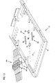
- the tray 16 of the splice tray arrangement 10 includes a generally planar bottom surface 24. Tray sides extend upward from or perpendicular to the bottom surface 24. In the illustrated embodiment, the tray sides include two opposing tray sides 26 and a tray side 28 transverse to the two opposing tray sides 26. The transverse tray side 28 is centrally located at a first end 30 of the tray 16. First and second cable access openings 32, 34 are located at opposite corners of the first end 30 of the tray 16 adjacent to the transverse tray side 28. The first and second cable access openings 32, 34 each function as a cable entry and/or a cable exit. A second end 36 of the tray 16 is an open end. The second open end 36 also functions as a cable entry and/or a cable exit of the splice tray arrangement 10.
- the fiber optic cables 12 can enter and exit through any of the first open end 36, the first cable access opening 32, and the second cable access opening 34 of the tray 16.
- the cables can be fixed at a particular entering and exiting location on the tray 16.
- apertures 48 are provided adjacent to the first open end 36 and the first and second cable access openings 32, 34 of the tray 16.
- a tie or other securing device (not shown) placed through the aperture(s) 48 can be used to tie or secure the cable 12 at the particular entering and exiting location.
- the cable management components 22 e.g. tabs of the splice tray arrangement 10 are formed along each of the sides 26, 28 of the tray 16.
- the tabs 22 retain cables within the interior storage region 20 of the tray 16.
- slots 43 are formed in the bottom surface 24 of the tray 16 opposite each of the tabs 22 for manufacturing purposes.
- the splice tray arrangement 10 can further include a cover (not shown).
- the tray 16 includes cover attachment structure 3 8 constructed to receive mating structure of the cover for securing the.cover to the tray.
- the cover attachment structure 38 includes openings 40 formed in at least one of the opposing sides 26 of the tray 16. In an alternative embodiment, the cover attachment structure 38 can be formed in the transverse side 28 of the splice tray 16.
- the tray 16 of the splice tray arrangement 10 is preferably a molded construction.
- the tray 16 can be molded from common engineering materials including common engineering polymers such as polybutylene terephthalate (PBT), polycarbonate (PC), polyethylene ether (PPE), and polystyrene (PS), for example.
- common engineering polymers such as polybutylene terephthalate (PBT), polycarbonate (PC), polyethylene ether (PPE), and polystyrene (PS), for example.
- the splice chip arrangement 18 of the present disclosure preferably includes at least a first splice chip 18A having a stackable configuration.
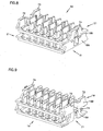
- the stackable configuration permits multiple splice chips (e.g., 18A and 18B shown in FIG. 2 ) to be stacked upon one another to increase splice element density of the splice tray arrangement 10, without reducing storage capacity.
- FIGS. 3-5 illustrate one of the splice chips (e.g., 18A) of the splice tray arrangement 10.
- the splice chips 18A, 18B shown in FIG. 2 are identical in construction; accordingly, the principles and constructions described with respect to the first splice chip 18A shown in FIGS. 3-5 also apply to the second splice chip 18B.
- the splice chip 18A generally includes a base 44 and a plurality of arms 46.
- the base 44 has a top side 61 ( FIG. 4 ) and a bottom side 63 ( FIG. 5 ).
- the plurality of arms 46 extends or projects upward from the top side 61 of the base 44.
- Each of the arms 46 has a free end 92 ( FIG. 4 ) and an opposite end 94 formed integral with the base 44.
- the arms 46 define slots or channels 52 ( FIG. 5 ) within which the splice elements 14 are placed and held. As shown in FIG. 5 , each of the channels 52 runs parallel to one another.
- the splice chip 18A includes six parallel channels 52.
- the arms 46 of the splice chip 18A are arranged in first and second rows of arms 62, 64.
- a row 54 of dividers 56 is located between the first and second rows of arms 62, 64.
- the channels 52 of the splice chip 18A are each partially defined by at least one arm 46 and one divider 54. As shown in FIG. 5 , the channels 52 have a height H defined by the arms 46. In the illustrated embodiment, the height H is at least about 160 inches to accommodate receipt of a splice element 14 having a diameter of similar dimension.
- the splice chip 18A preferably includes retaining structure 50 for retaining the splice elements 14 within the channels 52.
- the retaining structure 50 includes tabs or heads 80 located at the free ends 92 of the arms 46.
- the heads 80 are constructed and arranged to snap-fit the splice elements 14 securely within the channels 52.
- the splice element 14 rests upon first and second side edges 96, 98 ( FIGS. 3 and 4 ) of the base 44.
- the side edges 96, 98 include detents or cut-outs 99 that cradle the splice elements 14.
- the arms 46 of the splice chip 18A are flexible to provide the snap-fit retaining feature previously described.
- the flexible construction of the arms 46 can be provided by either or both of the choice of manufacturing material, or the dimensional construction of the arms.
- Materials that can be used to manufacture at least the arms 46 of the splice chip 18A include common engineering polymers such as polybutylene terephthalate (PBT), polycarbonate (PC), polyethylene ether (PPE), and polystyrene (PS), for example.
- a splice element 14 is inserted into one of the channels 52 by pressing the splice element 14 downward upon top ramped surfaces 39 ( FIG. 5 ) of the heads 80 of the associated arms 46.
- the downward force flexes the arms 46 outward to accept the splice element 14.
- the splice element 14 is retained within the channel 52 by the heads 80 of the arms 46.
- the dividers 56 of the splice chip 18A can be made of a more rigid construction.
- the dividers 56 for example, do not include retaining structure (e.g. 50) and therefore are not required to flex or function as a snap-fit retainer.
- the splice tray arrangement 10 typically mounts to the bottom surface 24 of the tray 16.
- the splice tray arrangement 10 includes a mounting arrangement 84 that detachably secures the splice chip 18A to the tray 16 without the use of adhesive or additional fasteners.
- the mounting arrangement 84 includes interlocking, longitudinal guides 86 ( FIG. 5 ), 88 ( FIG. 1 ) disposed on each of the splice chip 18A and the tray 16.
- the longitudinal guides 86 of the splice chip 18A includes an integrally formed lip or ledge 90 located at first and second opposite ends 19, 21 of the splice chip 18A.
- the ledges 90 extend laterally outward beyond ends 66, 68 of the base 44, and are offset or spaced a distance from the bottom side 63 of the base 44.
- the base 44 includes an angled portion 45 ( FIG. 5 ) at each of the ends 66, 68 adjacent to the guides 86.
- An interlocking space 47 is provided between each of the guides 86 and the angled portions 45 of the base 44 at the ends 19, 21 of the splice chip 18A.
- the longitudinal guides 88 of the tray 16 includes ribs or tracks 89 that project outward from the bottom surface 24 of the tray.
- the tracks 89 are integrally formed in the bottom surface 24 of the tray 16.
- the tracks 89 have a cross-sectional configuration corresponding to the interlocking space 47 provided by the splice chip 18A.
- the inverse, cross-sectional configuration of the tracks 89 slide within the interlocking spaces 47 of the splice chip 18A to secure the splice chip 18A to the bottom surface 24 of the tray 16.
- the splice chip 18A slides in a lateral direction A, as shown in FIG. 1 , such that the interlocking guides 86, 88 of the mounting arrangement 84 engage one another.
- the splice chip 18A can be secured to the tray 16 by sliding the splice chip 18A in an opposite lateral direction B.
- the interlocking guides 86, 88 of the mounting arrangement 84 are engaged, the splice chip 18A is prevented from movement in a direction transverse to the bottom surface 24 of the tray.
- the splice chip arrangement 18 is preferably constructed to accommodate an increased density of splice elements 14 ( FIG. 2 ) without reducing storage capacity within the splice tray arrangement 10.
- the splice chips 18A, 18B are thereby stackable. That is, the splice chips 18A, 18B are constructed to stack on top of one another at a particular splice chip mounting location 42 ( FIG. 13 ) of the tray 16. As shown in FIG. 13 , the splice chip mounting location 42 is generally defined between the tracks 89 of the mounting arrangement 84.
- each of the splice chips 18A, 18B includes a snap-fit stacking arrangement 60 that detachably secures the splice chips in relation to one another.
- the splice chips 18A, 18B are stacked on top of one another. While referred to as being stacked on top of one another, it will be appreciated that the splice chips 18A, 18B need not be limited to a vertically stacked arrangement. Rather, the phrase "stacked on top of one another" is used for explanatory purposes of the illustrated embodiment.
- the splice chips may be stacked in a front-to-back arrangement depending upon the orientation of the tray, for example.
- the stacking arrangement 60 of the splice chips 18A, 18B is configured to function interchangeably with the mounting arrangement 84 of the splice tray arrangement 10. That is, the stacking arrangement 60 includes the interlocking guides 86 of the mounting arrangement 84 so that both the stacking arrangement 60 and the mounting arrangement 84 function to mount the splice chip to another splice chip, and to mount the splice chip to the tray 16.
- the splice chips 18A, 18B are interchangeable and need not be dedicated as only a stackable chip or tray-mounted chip.
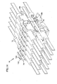
- the stacking arrangement 60 of each of the splice chips 18A, 18B further includes first and second latch members 70, 72 located at the first end 19 of the splice chip 18A, 18B, and a third latch member 74 located at the second opposite end 21 of the splice chip.
- the latch members 70, 72, 74 of each of the splice chips are configured to engage or latch into the interlocking spaces 47 of another splice chip.
- first, second, and third slots 71, 73, 75 are formed in the ends 66, 68 of the base 44 for purposes of manufacturing.
- the slots 71, 73, 75 defined segments of interlocking spaces 47 that correspond to the arrangement of latch members 70, 72, 74.
- the stacked splice chips 18A, 18B are accordingly stacked in an alternating manner to accommodate the arrangement of slots and latch members. That is, opposite ends (e.g., 19 and 21) of the first and second splice chips 18A, 18B are constructed to interlock with one another.
- the ends 66, 68 of the base 44 can be manufactured without slots, thereby permitting same ends (e.g. 19 and 19) of the first and second splice chips to interlock.
- the first and second latch members 70, 72 at the first end 19 of the bottom splice chip 18A are positioned within the interlocking spaces 47 ( FIGS. 10 and 12 ) provided at the second end 21 of the top splice chip 18B.
- the top splice chip 18B is then pivoted such that the third latch member 74 at the second end 21 of the bottom splice chip 18A snap fits into the interlocking space 47 ( FIG. 11 ) provided at the first end 19 of the top splice chip 18B.
- the third latch member 74 of the bottom splice chip 18A can initially be engaged within the interlocking space provided on the top splice chip 18B, and then the first and second latch members snap fit into the associate interlocking spaces 47 at the other end of the top splice chip 18B.
- At least one of the third latch member 74, and the first and second latch members 70, 72 of the stacking arrangement 60 is flexible to provide the snap-fit retaining feature described.
- the flexible construction of the latch member(s) can be provided by either or both of the choice of manufacturing material and the dimensional construction of the latch member(s).
- the bottom side 63 of the base 44 includes at least a first recess 82.
- the recess 82 is sized to receive a guide 58 ( FIG. 3 ) disposed on top of one of the dividers 56 of the splice chip 18A, 18B.
- two guides 58 ( FIG. 3 ) and recesses 82 are provided on the splice chips 18A, 18B.
- the guides 58 and recesses 82 are arranged to assist in properly locating or aligning the top splice chip 18B in relation to the bottom splice chip 18A.
- the guides 58 and recesses 82 further assist in preventing lateral movement of the top splice chip 18B relative to the bottom splice chip 18A when secured in the stacked relationship.
- the first splice chip 18A is attached to the bottom surface 24 of the tray 16.
- the first splice chip 18A slides in the lateral direction A ( FIG. 1 ) so that the interlocking guides 86, 88 of the splice chip 18A and tray 16 engage.
- Flexible securing tabs 76, 78 are provided to prevent the splice chip 18A from inadvertent lateral movement beyond the chip mounting location 42.
- splice elements 14 can then be placed into the channels 52 of the splice chip.
- the second splice chip 18B can be stacked upon the first splice chip 18A.
- the second splice chip 18B is attached to the first splice chip 18A in the manner previously described. Additional splice elements 14 can then be placed and secured within the channels 52 of the second splice chip 18B.
- the splice elements 14 can be placed within the channels 52 of the splice chips 18A, 18B prior to securing the chips to either the tray 16 or one another. As shown in FIG. 14 , a total of twelve splice elements 14 can be held by the illustrated splice chip arrangement 18.
- each of the splice chips 18A, 18B includes a release tab 100 for detaching the top splice chip (e.g., 18B) from the stack of splice chips.
- the release tab 100 is located adjacent to a top edge 102 of the third latch member 74.
- the top splice chip 18B can then be removed from the stack by pivoting the splice chip 18B upward and disengaging the splice chip from the first and second latch members 70, 72 of the bottom splice chip 18A.
- the bottom splice chip 18A can be removed from the tray 16, by pressing one of the flexible securing tabs 76, 78 flush with the bottom surface 24 of the tray 16, and laterally sliding the chip 18A such that the interlocking guides 86, 88 of the splice chip and tray disengage.
- the overall arrangement and construction of the disclosed splice tray arrangement 10 enhances cable management by providing a splice chip arrangement that is easy to use and increases splice element density.
Abstract
Description
- This disclosure relates generally to devices used in the telecommunications industry. More particularly, this disclosure relates to a splice chip arrangement for use in holding fiber optic splice elements.
- A wide variety of telecommunication applications utilize fiber optic cables, and in turn involve fiber optic cable splicing and fiber optic cable storage. In these applications, a splice tray is often used to store spiced fiber optic cables. The splice trays commonly include a splice chip for holding or retaining the splice elements of the cables.
- In general, improvement has been sought with respect to conventional splice tray arrangements, generally to better accommodate ease of use, and to increase the density of spice elements that can be stored and managed by the splice tray arrangement.
- Further information pertaining to the prior art can be found in
US patent 5,450,518 that discloses a splice closure for optical fiber cables having an outer two pan shell, an interior longitudinally extending spine member held within the shell and cable sheath gripping members mounted on the ends of the spine member. A splice tray is removably mounted on the spine member intermediate its ends, and a plurality of splice holders are stacked on the splice tray. Each splice holder has grooves for containing the individual splices and means for affixing the individual splices to the holder. A splice tray cover contains means for applying compressive force to the stack of holders to hold them in place on the splice tray. -
GB 2 367 379 - The present invention provides a splice chip arrangement in accordance with
independent claim 1, a splice tray arrangement in accordance with dependent claim 7 and a method of assembling a splice tray arrangement in accordance with independent claim 13. Further preferred embodiments of the invention are reflected in the claims dependent therefrom. - The claimed invention can be better understood in view of the embodiments described and illustrated in the present disclosure, viz. in the present specification and drawings. In general, the present disclosure reflects preferred embodiments of the invention. The attentive reader will note, however, that some aspects of the disclosed embodiments extend beyond the scope of the claims. To the respect that the disclosed embodiments indeed extend beyond the scope of the claims, the disclosed embodiments are to be considered supplementary background information and do not constitute definitions of the invention per se.
- The present disclosure relates to a splice chip having a mounting arrangement for securing the splice chip to a splice tray. The mounting arrangement also permits the splice chip to be secured to a second splice chip in a stacked relationship. The stacked configuration of the splice chips increases the splice element density within the splice tray, without reducing storage capacity.
- A variety of examples of desirable product features or methods are set forth in part in the description that follows, and in part will be apparent from the description, or may be learned by practicing various aspects of the disclosures. The aspects of the disclosure may relate to individual features as well as combinations of features. It is to be understood that both the foregoing general description and the following detailed description are explanatory only, and are not restrictive of the claimed invention.
-
-
FIG. 1 is a perspective view of one embodiment of a splice tray arrangement, including an embodiment of a first splice chip, according to the principles of the present disclosure; -
FIG. 2 is a perspective view of the splice tray arrangement ofFIG. 1 , including a second splice chip; -
FIG. 3 is a side perspective view of one of the first and second splice chips ofFIGS. 1 and2 ; -
FIG. 4 is an opposite side perspective view of the splice chip ofFIG. 3 ; -
FIG. 5 is side elevation view of the splice chip ofFIG. 3 ; -
FIG. 6 is a side perspective view of the first and second splice chips ofFIG. 2 ; -
FIG. 7 is an opposite side perspective view of the first and second splice chips ofFIG. 6 ; -
FIG. 8 is another side perspective view of the first and second splice chips ofFIG. 6 ; -
FIG. 9 is an opposite side perspective view of the first and second splice chips ofFIG. 8 ; -
FIG. 10 is a bottom perspective view of the splice chip ofFIG. 4 ; -
FIG. 11 is an end elevation view of the splice chip ofFIG. 5 ; -
FIG. 12 is an opposite end elevation view of the splice chip ofFIG. 11 ; -
FIG. 13 is a perspective view of the splice tray arrangement ofFIG. 1 , showing placement of the first splice chip; and -
FIG. 14 is a perspective view of the first and second splice chips ofFIG. 7 , shown with splice elements. - Reference will now be made in detail to various features of the present disclosure that are illustrated in the accompanying drawings. Wherever possible, the same reference numbers will be used throughout the drawings to refer to the same or like parts.
-
FIGS. 1 and2 illustrate an embodiment of asplice tray arrangement 10 having features that are examples of how inventive aspects in accordance with the principles of the present disclosure may be practiced. One of the preferred features relates to increasing the splice element density of the splice tray arrangement without reducing storage capacity. - As shown in
FIGS. 1 and2 , thesplice tray arrangement 10 is used to house spliced fiberoptic cables 12. In splicing fiber optic cables, two fiber optic cables are joined or spliced together by asplice element 14. The illustratedsplice element 14 is a cylindrical, mass fusion splice element used to join multiple optic fibers of a ribbon cable. In accordance with the principles disclosed, the splice tray arrangement can be constructed and sized for use with other types of splice elements, such as stranded heat shrink splice elements used to join single-fiber cables, for example. - The
splice tray arrangement 10 of the present disclosure generally includes a base ortray 16 and asplice chip arrangement 18 for holding or retaining thesplice elements 14. Often, in use, a generous portion of slack cable is provided to permit maintenance or replacement of thesplice elements 14 without requiring complete cable replacement. The slack cable is stored within aninterior storage region 20 of thetray 16.Cable management components 22, such as tabs, are located within thestorage region 20 for retaining and managing the slack cable. - Referring still to
FIG. 1 , thetray 16 of thesplice tray arrangement 10 includes a generallyplanar bottom surface 24. Tray sides extend upward from or perpendicular to thebottom surface 24. In the illustrated embodiment, the tray sides include two opposingtray sides 26 and atray side 28 transverse to the two opposingtray sides 26. Thetransverse tray side 28 is centrally located at afirst end 30 of thetray 16. First and secondcable access openings first end 30 of thetray 16 adjacent to thetransverse tray side 28. The first and secondcable access openings second end 36 of thetray 16 is an open end. The secondopen end 36 also functions as a cable entry and/or a cable exit of thesplice tray arrangement 10. - In use, the
fiber optic cables 12 can enter and exit through any of the firstopen end 36, the first cable access opening 32, and the second cable access opening 34 of thetray 16. To manage the organization of cables entering and exiting thetray 16, the cables can be fixed at a particular entering and exiting location on thetray 16. In particular,apertures 48 are provided adjacent to the firstopen end 36 and the first and secondcable access openings tray 16. A tie or other securing device (not shown) placed through the aperture(s) 48 can be used to tie or secure thecable 12 at the particular entering and exiting location. - The cable management components 22 (e.g. tabs) of the
splice tray arrangement 10 are formed along each of thesides tray 16. Thetabs 22 retain cables within theinterior storage region 20 of thetray 16. In the illustrated embodiment,slots 43 are formed in thebottom surface 24 of thetray 16 opposite each of thetabs 22 for manufacturing purposes. - The
splice tray arrangement 10 can further include a cover (not shown). Thetray 16 includes cover attachment structure 3 8 constructed to receive mating structure of the cover for securing the.cover to the tray. In the illustrated embodiment, thecover attachment structure 38 includesopenings 40 formed in at least one of the opposingsides 26 of thetray 16. In an alternative embodiment, thecover attachment structure 38 can be formed in thetransverse side 28 of thesplice tray 16. - The
tray 16 of thesplice tray arrangement 10 is preferably a molded construction. Thetray 16 can be molded from common engineering materials including common engineering polymers such as polybutylene terephthalate (PBT), polycarbonate (PC), polyethylene ether (PPE), and polystyrene (PS), for example. - The
splice chip arrangement 18 of the present disclosure preferably includes at least afirst splice chip 18A having a stackable configuration. The stackable configuration permits multiple splice chips (e.g., 18A and 18B shown inFIG. 2 ) to be stacked upon one another to increase splice element density of thesplice tray arrangement 10, without reducing storage capacity.FIGS. 3-5 illustrate one of the splice chips (e.g., 18A) of thesplice tray arrangement 10. Generally, thesplice chips FIG. 2 are identical in construction; accordingly, the principles and constructions described with respect to thefirst splice chip 18A shown inFIGS. 3-5 also apply to thesecond splice chip 18B. - The
splice chip 18A generally includes abase 44 and a plurality ofarms 46. Thebase 44 has a top side 61 (FIG. 4 ) and a bottom side 63 (FIG. 5 ). The plurality ofarms 46 extends or projects upward from thetop side 61 of thebase 44. Each of thearms 46 has a free end 92 (FIG. 4 ) and anopposite end 94 formed integral with thebase 44. Thearms 46 define slots or channels 52 (FIG. 5 ) within which thesplice elements 14 are placed and held. As shown inFIG. 5 , each of thechannels 52 runs parallel to one another. In the illustrated embodiment, thesplice chip 18A includes sixparallel channels 52. - Referring to
FIGS. 3 and 4 , thearms 46 of thesplice chip 18A are arranged in first and second rows ofarms row 54 ofdividers 56 is located between the first and second rows ofarms channels 52 of thesplice chip 18A are each partially defined by at least onearm 46 and onedivider 54. As shown inFIG. 5 , thechannels 52 have a height H defined by thearms 46. In the illustrated embodiment, the height H is at least about 160 inches to accommodate receipt of asplice element 14 having a diameter of similar dimension. - As shown in
FIGS. 3-5 , thesplice chip 18A preferably includes retainingstructure 50 for retaining thesplice elements 14 within thechannels 52. In the illustrated embodiment, the retainingstructure 50 includes tabs or heads 80 located at the free ends 92 of thearms 46. Theheads 80 are constructed and arranged to snap-fit thesplice elements 14 securely within thechannels 52. When placed in thechannel 52, thesplice element 14 rests upon first and second side edges 96, 98 (FIGS. 3 and 4 ) of thebase 44. In the illustrated embodiments, the side edges 96, 98 include detents or cut-outs 99 that cradle thesplice elements 14. - As can be understood, preferably the
arms 46 of thesplice chip 18A are flexible to provide the snap-fit retaining feature previously described. The flexible construction of thearms 46 can be provided by either or both of the choice of manufacturing material, or the dimensional construction of the arms. Materials that can be used to manufacture at least thearms 46 of thesplice chip 18A, include common engineering polymers such as polybutylene terephthalate (PBT), polycarbonate (PC), polyethylene ether (PPE), and polystyrene (PS), for example. - In use, a
splice element 14 is inserted into one of thechannels 52 by pressing thesplice element 14 downward upon top ramped surfaces 39 (FIG. 5 ) of theheads 80 of the associatedarms 46. The downward force flexes thearms 46 outward to accept thesplice element 14. Thesplice element 14 is retained within thechannel 52 by theheads 80 of thearms 46. In contrast to the flexible construction of thearms 46, thedividers 56 of thesplice chip 18A can be made of a more rigid construction. Thedividers 56, for example, do not include retaining structure (e.g. 50) and therefore are not required to flex or function as a snap-fit retainer. - Referring back to
FIG. 1 , thesplice chip 18A of the present disclosure typically mounts to thebottom surface 24 of thetray 16. Thesplice tray arrangement 10 includes a mountingarrangement 84 that detachably secures thesplice chip 18A to thetray 16 without the use of adhesive or additional fasteners. The mountingarrangement 84 includes interlocking, longitudinal guides 86 (FIG. 5 ), 88 (FIG. 1 ) disposed on each of thesplice chip 18A and thetray 16. - Referring back to
FIGS. 3-5 , thelongitudinal guides 86 of thesplice chip 18A includes an integrally formed lip orledge 90 located at first and second opposite ends 19, 21 of thesplice chip 18A. Theledges 90 extend laterally outward beyond ends 66, 68 of thebase 44, and are offset or spaced a distance from thebottom side 63 of thebase 44. Thebase 44 includes an angled portion 45 (FIG. 5 ) at each of theends guides 86. An interlockingspace 47 is provided between each of theguides 86 and theangled portions 45 of the base 44 at theends splice chip 18A. - Referring now to
FIG. 13 , thelongitudinal guides 88 of thetray 16 includes ribs or tracks 89 that project outward from thebottom surface 24 of the tray. In the illustrated embodiment, thetracks 89 are integrally formed in thebottom surface 24 of thetray 16. Thetracks 89 have a cross-sectional configuration corresponding to the interlockingspace 47 provided by thesplice chip 18A. The inverse, cross-sectional configuration of thetracks 89 slide within the interlockingspaces 47 of thesplice chip 18A to secure thesplice chip 18A to thebottom surface 24 of thetray 16. - When securing the
splice chip 18A to thetray 16, thesplice chip 18A slides in a lateral direction A, as shown inFIG. 1 , such that the interlocking guides 86, 88 of the mountingarrangement 84 engage one another. In the alternative, thesplice chip 18A can be secured to thetray 16 by sliding thesplice chip 18A in an opposite lateral direction B. When the interlocking guides 86, 88 of the mountingarrangement 84 are engaged, thesplice chip 18A is prevented from movement in a direction transverse to thebottom surface 24 of the tray. - Referring now to
FIGS. 6-10 , thesplice chip arrangement 18 is preferably constructed to accommodate an increased density of splice elements 14 (FIG. 2 ) without reducing storage capacity within thesplice tray arrangement 10. The splice chips 18A, 18B are thereby stackable. That is, thesplice chips FIG. 13 ) of thetray 16. As shown inFIG. 13 , the splicechip mounting location 42 is generally defined between thetracks 89 of the mountingarrangement 84. - Referring to
FIGS. 6 and 7 , each of thesplice chips fit stacking arrangement 60 that detachably secures the splice chips in relation to one another. In the illustrated embodiment, thesplice chips splice chips - Preferably, the stacking
arrangement 60 of thesplice chips arrangement 84 of thesplice tray arrangement 10. That is, the stackingarrangement 60 includes the interlocking guides 86 of the mountingarrangement 84 so that both the stackingarrangement 60 and the mountingarrangement 84 function to mount the splice chip to another splice chip, and to mount the splice chip to thetray 16. By this, thesplice chips - Still referring to
FIGS. 6 and 7 , the stackingarrangement 60 of each of thesplice chips second latch members first end 19 of thesplice chip third latch member 74 located at the secondopposite end 21 of the splice chip. Thelatch members spaces 47 of another splice chip. - Referring now to
FIG. 10 , first, second, andthird slots ends base 44 for purposes of manufacturing. Theslots spaces 47 that correspond to the arrangement oflatch members stacked splice chips second splice chips - As shown in
FIGS. 6 and 7 , to assemble thesplice chips second latch members first end 19 of thebottom splice chip 18A are positioned within the interlocking spaces 47 (FIGS. 10 and 12 ) provided at thesecond end 21 of thetop splice chip 18B. Referring now toFIGS. 8 and 9 , thetop splice chip 18B is then pivoted such that thethird latch member 74 at thesecond end 21 of thebottom splice chip 18A snap fits into the interlocking space 47 (FIG. 11 ) provided at thefirst end 19 of thetop splice chip 18B. In the alternative, thethird latch member 74 of thebottom splice chip 18A can initially be engaged within the interlocking space provided on thetop splice chip 18B, and then the first and second latch members snap fit into the associate interlockingspaces 47 at the other end of thetop splice chip 18B. - As can be understood, preferably at least one of the
third latch member 74, and the first andsecond latch members arrangement 60 is flexible to provide the snap-fit retaining feature described. The flexible construction of the latch member(s) can be provided by either or both of the choice of manufacturing material and the dimensional construction of the latch member(s). - Referring again to
FIG. 10 , thebottom side 63 of thebase 44 includes at least afirst recess 82. Therecess 82 is sized to receive a guide 58 (FIG. 3 ) disposed on top of one of thedividers 56 of thesplice chip FIG. 3 ) and recesses 82 are provided on thesplice chips guides 58 and recesses 82 are arranged to assist in properly locating or aligning thetop splice chip 18B in relation to thebottom splice chip 18A. Theguides 58 and recesses 82 further assist in preventing lateral movement of thetop splice chip 18B relative to thebottom splice chip 18A when secured in the stacked relationship. - In use, to assembly of the
splice tray arrangement 10, thefirst splice chip 18A is attached to thebottom surface 24 of thetray 16. In particular, thefirst splice chip 18A slides in the lateral direction A (FIG. 1 ) so that the interlocking guides 86, 88 of thesplice chip 18A andtray 16 engage.Flexible securing tabs 76, 78 (FIG. 13 ) are provided to prevent thesplice chip 18A from inadvertent lateral movement beyond thechip mounting location 42. - When the
first splice chip 18A is secured to thetray 16,splice elements 14 can then be placed into thechannels 52 of the splice chip. After placing the desired number ofsplice elements 14 within thechannels 52first splice chip 18A, thesecond splice chip 18B can be stacked upon thefirst splice chip 18A. Thesecond splice chip 18B is attached to thefirst splice chip 18A in the manner previously described.Additional splice elements 14 can then be placed and secured within thechannels 52 of thesecond splice chip 18B. In the alternative, thesplice elements 14 can be placed within thechannels 52 of thesplice chips tray 16 or one another. As shown inFIG. 14 , a total of twelvesplice elements 14 can be held by the illustratedsplice chip arrangement 18. - Referring now to
FIG. 14 , each of thesplice chips release tab 100 for detaching the top splice chip (e.g., 18B) from the stack of splice chips. Therelease tab 100 is located adjacent to atop edge 102 of thethird latch member 74. When a downward or outward pulling force F is applied to thetab 100 of thelower splice chip 18A, thelatch member 74 of thelower splice chip 18A flexes outward and thereby disengages from the interlockingspace 47 of thetop splice chip 18B. Thetop splice chip 18B can then be removed from the stack by pivoting thesplice chip 18B upward and disengaging the splice chip from the first andsecond latch members bottom splice chip 18A. Thebottom splice chip 18A can be removed from thetray 16, by pressing one of theflexible securing tabs bottom surface 24 of thetray 16, and laterally sliding thechip 18A such that the interlocking guides 86, 88 of the splice chip and tray disengage. - The overall arrangement and construction of the disclosed
splice tray arrangement 10 enhances cable management by providing a splice chip arrangement that is easy to use and increases splice element density.
Claims (17)
- A splice chip arrangement (18) that mounts to a splice tray (16), the splice chip arrangement comprising:a) a first splice chip (18A) and a second splice chip (18B) secured to one another in a stacked relationship, each of the first and second splice chips including:i) a base (44) having a first end (66) and a second opposite end (68);ii) a plurality of channels (52) sized to receive splice elements (14);iii) a latch member (70, 72, 74) located at the each of the first and second ends of the splice chip; andiv) a ledge (90) extending from a top surface of the base at each of the first and second ends of the splice chip;v) wherein an interlocking space is defined between each ledge (90) and an angled portion (45) of the base located beneath the ledge;b) wherein the latch members and interlocking spaces (47) cooperate such that the first end of the first splice chip pivotally interconnects to the second end of the second splice chip, and wherein the second end of the first splice chip snap-fits to the first end of the second splice chip;c) wherein at least one of the first and second splice chips includes a release element (100) for detaching the first and second splice chips from one another.
- The splice chip arrangement of claim 1, wherein said release element is a release tab (100).
- The splice chip arrangement of claim 1, wherein the latches and the interlocking spaces of the first and second splice chips are configured to detachably secure the splice chips in relation to one another such that each splice chip is selectively positionable in both of either one of a top position relative to the other splice chip or a bottom position relative to the other splice chip.
- The splice chip arrangement of claim 3, wherein the interlocking space of the first and second splice chips is further configured to selectively attach the splice chip arrangement to a tray (16).
- The splice chip arrangement of claim 1, further including a recess (82) formed in a bottom surface of the base of one of the first and second splice chips, and a guide structure (58) located adjacent to the channels of the other of the first and second splice chips, the recess of the one splice chip being configured to receive the guide structure of the other splice chip to prevent lateral movement of the splice chips relative to one another.
- The splice chip arrangement of claim 1, further including a recess (82) formed in a bottom surface of the base of one of the first and second splice chips, and an alignment guide (58) located adjacent to the channels of the other of the first and second splice chips, the recess of the one splice chip being configured to receive the alignment guide of the other splice chip to align the splice chips in relation to one another.
- A splice tray arrangement (10), comprising:a) a tray (16) having a splice chip mounting location; andb) a splice chip arrangement (18) in accordance with claim 1 or 2 whereinthe first splice chip is positioned at the mounting location, the first splice chip including a plurality of splice holding structures, the first splice chip including a mounting structure configured such that the first splice chip laterally slides into position at the mounting location; and
the second splice chip is disposed on the first splice chip at the mounting location, the second splice chip including a plurality of splice holding structures. - The splice tray arrangement of claim 7, wherein each of the first and second splice chips include interlocking guides (70, 72, 74, 90) for attaching to both of either one of the tray and the other of the first and second splice chips.
- The splice tray arrangement of claim 7, wherein one of the first and second splice chips includes a recess (82) formed in a bottom surface of the base, and wherein the other of the first and second splice chips includes an alignment guide (58), the recess and the alignment guide being arranged to align the splice chips in relation to one another.
- The splice tray arrangement of claim 7, wherein one of the first and second splice chips includes a latch member (70, 72, 74), and the other of the first and second splice chips includes an interlocking space (47) defined between a base (44) and a ledge (90) projecting outward beyond the base, the latch member of the one splice chip being engaged with the interlocking space of the other splice chip.
- The splice tray arrangement of claim 10, wherein the latch member of the one splice chip snap fits within the interlocking space of the other splice chip.
- The splice tray arrangement of claim 7, wherein the first and second splice chips snap fit together.
- A method of assembling a splice tray arrangement (10), according to claim 1, the method comprising the steps of:a) securing a first splice chip (18A) to a tray (16) at a mounting location by sliding the first splice chip in a lateral direction along a mounting surface of the tray; andb) securing a second splice chip (18B) to the first splice chip at the mounting location, said securing comprising engaging the first and second splice chips and pivoting the second splice chip relative to the first splice chip to effect a snap fitting.
- The method of claim 13, further including positioning a number of splice elements in both of the first and second splice chips.
- The method of claim 13, wherein the step of securing the second splice chip to the first splice chip at the mounting location is accomplished without reducing storage space within the tray.
- The method of claim 13, wherein each of the first splice chip and the tray have interlocking, longitudinal guides (86, 88) disposed thereon and said sliding is carried out such that the interlocking, longitudinal guides of the first splice chip engage the interlocking, longitudinal guides of the tray.
- The method of claim 13 or 16, wherein said engaging consists of positioning latch members (70, 72) at a first end (19) of the first splice chip within interlocking spaces (47) provided at a second end (21) of the second splice chip and said pivoting consists of pivoting the second splice chip such that a latch member (74) at a second end (21) of the first splice chip snap fits into an interlocking space (47) provided at a first end (19) of the second splice chip.
Applications Claiming Priority (2)
| Application Number | Priority Date | Filing Date | Title |
|---|---|---|---|
| US11/212,470 US7310471B2 (en) | 2005-08-25 | 2005-08-25 | Stackable splice chip device |
| PCT/US2006/032859 WO2007024912A1 (en) | 2005-08-25 | 2006-08-22 | Stackable splice chip device |
Publications (2)
| Publication Number | Publication Date |
|---|---|
| EP1929348A1 EP1929348A1 (en) | 2008-06-11 |
| EP1929348B1 true EP1929348B1 (en) | 2011-10-12 |
Family
ID=37433729
Family Applications (1)
| Application Number | Title | Priority Date | Filing Date |
|---|---|---|---|
| EP06802138A Not-in-force EP1929348B1 (en) | 2005-08-25 | 2006-08-22 | Stackable splice chip device |
Country Status (10)
| Country | Link |
|---|---|
| US (3) | US7310471B2 (en) |
| EP (1) | EP1929348B1 (en) |
| JP (1) | JP2009506362A (en) |
| KR (1) | KR20080039489A (en) |
| CN (1) | CN101243347B (en) |
| AT (1) | ATE528677T1 (en) |
| AU (1) | AU2006283165B2 (en) |
| BR (1) | BRPI0615366A2 (en) |
| ES (1) | ES2370263T3 (en) |
| WO (1) | WO2007024912A1 (en) |
Cited By (1)
| Publication number | Priority date | Publication date | Assignee | Title |
|---|---|---|---|---|
| IT202000007045A1 (en) | 2020-04-02 | 2021-10-02 | Prysmian Spa | Tray for fiber optic splices |
Families Citing this family (106)
| Publication number | Priority date | Publication date | Assignee | Title |
|---|---|---|---|---|
| US7310471B2 (en) * | 2005-08-25 | 2007-12-18 | Adc Telecommunications, Inc. | Stackable splice chip device |
| US7272291B2 (en) * | 2005-08-25 | 2007-09-18 | Adc Telecommunications, Inc. | Splice chip device |
| DE102007009223B4 (en) * | 2007-02-26 | 2011-03-17 | Adc Gmbh | Strain relief for cables |
| US7822310B2 (en) | 2007-02-28 | 2010-10-26 | Corning Cable Systems Llc | Fiber optic splice trays |
| US8798427B2 (en) | 2007-09-05 | 2014-08-05 | Corning Cable Systems Llc | Fiber optic terminal assembly |
| WO2009048795A1 (en) * | 2007-10-09 | 2009-04-16 | 3M Innovative Properties Company | Splice holder with ejector |
| DE202008002812U1 (en) * | 2008-02-28 | 2008-04-24 | CCS Technology, Inc., Wilmington | Holding device for splice protection devices with splices of optical waveguides received in the splice protection devices |
| US7889961B2 (en) | 2008-03-27 | 2011-02-15 | Corning Cable Systems Llc | Compact, high-density adapter module, housing assembly and frame assembly for optical fiber telecommunications |
| US8009954B2 (en) * | 2008-04-21 | 2011-08-30 | Adc Telecommunications, Inc. | Fiber optic splice tray |
| US8761563B2 (en) | 2008-04-21 | 2014-06-24 | Afl Telecommunications Llc | Fiber optic splice tray |
| US8290333B2 (en) | 2008-08-29 | 2012-10-16 | Corning Cable Systems Llc | Fiber optic cable assemblies with furcation bodies having features for manufacturing and methods of making the same |
| US8452148B2 (en) | 2008-08-29 | 2013-05-28 | Corning Cable Systems Llc | Independently translatable modules and fiber optic equipment trays in fiber optic equipment |
| US8135257B2 (en) * | 2008-08-29 | 2012-03-13 | Corning Cable Systems Llc | Structures for managing and mounting cable assemblies |
| US8301004B2 (en) * | 2008-08-29 | 2012-10-30 | Corning Cable Systems Llc | Fiber optic cable assemblies employing a furcation body having anti-rotation feature |
| US11294135B2 (en) | 2008-08-29 | 2022-04-05 | Corning Optical Communications LLC | High density and bandwidth fiber optic apparatuses and related equipment and methods |
| US8086084B2 (en) * | 2008-09-09 | 2011-12-27 | Adc Telecommunications, Inc. | Fiber optic splice tray |
| EP2344915A4 (en) | 2008-10-09 | 2015-01-21 | Corning Cable Sys Llc | Fiber optic terminal having adapter panel supporting both input and output fibers from an optical splitter |
| US8879882B2 (en) | 2008-10-27 | 2014-11-04 | Corning Cable Systems Llc | Variably configurable and modular local convergence point |
| US8165442B2 (en) * | 2008-11-06 | 2012-04-24 | Ofs Fitel, Llc | System for securing fiber optic devices in management trays |
| US8494329B2 (en) * | 2009-01-15 | 2013-07-23 | Adc Telecommunications, Inc. | Fiber optic module and chassis |
| ATE534049T1 (en) | 2009-02-24 | 2011-12-15 | Ccs Technology Inc | CABLE HOLDING DEVICE OR ARRANGEMENT FOR USE WITH A CABLE |
| EP2237091A1 (en) | 2009-03-31 | 2010-10-06 | Corning Cable Systems LLC | Removably mountable fiber optic terminal |
| US8699838B2 (en) | 2009-05-14 | 2014-04-15 | Ccs Technology, Inc. | Fiber optic furcation module |
| US8538226B2 (en) | 2009-05-21 | 2013-09-17 | Corning Cable Systems Llc | Fiber optic equipment guides and rails configured with stopping position(s), and related equipment and methods |
| US9075216B2 (en) | 2009-05-21 | 2015-07-07 | Corning Cable Systems Llc | Fiber optic housings configured to accommodate fiber optic modules/cassettes and fiber optic panels, and related components and methods |
| JP2012530943A (en) | 2009-06-19 | 2012-12-06 | コーニング ケーブル システムズ リミテッド ライアビリティ カンパニー | High fiber optic cable packaging density equipment |
| US8712206B2 (en) | 2009-06-19 | 2014-04-29 | Corning Cable Systems Llc | High-density fiber optic modules and module housings and related equipment |
| US7945136B2 (en) * | 2009-06-19 | 2011-05-17 | Corning Cable Systems Llc | Mounting of fiber optic cable assemblies within fiber optic shelf assemblies |
| ES2793952T3 (en) | 2009-06-19 | 2020-11-17 | Corning Optical Communications LLC | High Density and Bandwidth Fiber Optic Apparatus |
| US8467651B2 (en) * | 2009-09-30 | 2013-06-18 | Ccs Technology Inc. | Fiber optic terminals configured to dispose a fiber optic connection panel(s) within an optical fiber perimeter and related methods |
| US8625950B2 (en) | 2009-12-18 | 2014-01-07 | Corning Cable Systems Llc | Rotary locking apparatus for fiber optic equipment trays and related methods |
| EP2354824A1 (en) * | 2010-01-29 | 2011-08-10 | CCS Technology Inc. | Hybrid connector |
| US8992099B2 (en) | 2010-02-04 | 2015-03-31 | Corning Cable Systems Llc | Optical interface cards, assemblies, and related methods, suited for installation and use in antenna system equipment |
| AU2011224314A1 (en) | 2010-03-10 | 2012-09-06 | Corning Cable Systems Llc | Fiber optic pigtail assembly allowing single and mass splicing |
| US9547144B2 (en) | 2010-03-16 | 2017-01-17 | Corning Optical Communications LLC | Fiber optic distribution network for multiple dwelling units |
| US8913866B2 (en) | 2010-03-26 | 2014-12-16 | Corning Cable Systems Llc | Movable adapter panel |
| US8792767B2 (en) | 2010-04-16 | 2014-07-29 | Ccs Technology, Inc. | Distribution device |
| EP2558895B1 (en) | 2010-04-16 | 2019-04-17 | Corning Optical Communications LLC | Sealing and strain relief device for data cables |
| EP2381284B1 (en) | 2010-04-23 | 2014-12-31 | CCS Technology Inc. | Under floor fiber optic distribution device |
| US8385711B2 (en) | 2010-04-30 | 2013-02-26 | Corning Cable Systems Llc | Multi-configurable splice holder |
| US9720195B2 (en) | 2010-04-30 | 2017-08-01 | Corning Optical Communications LLC | Apparatuses and related components and methods for attachment and release of fiber optic housings to and from an equipment rack |
| US8879881B2 (en) | 2010-04-30 | 2014-11-04 | Corning Cable Systems Llc | Rotatable routing guide and assembly |
| US9519118B2 (en) | 2010-04-30 | 2016-12-13 | Corning Optical Communications LLC | Removable fiber management sections for fiber optic housings, and related components and methods |
| US8705926B2 (en) | 2010-04-30 | 2014-04-22 | Corning Optical Communications LLC | Fiber optic housings having a removable top, and related components and methods |
| US9632270B2 (en) | 2010-04-30 | 2017-04-25 | Corning Optical Communications LLC | Fiber optic housings configured for tool-less assembly, and related components and methods |
| US8660397B2 (en) | 2010-04-30 | 2014-02-25 | Corning Cable Systems Llc | Multi-layer module |
| US9075217B2 (en) | 2010-04-30 | 2015-07-07 | Corning Cable Systems Llc | Apparatuses and related components and methods for expanding capacity of fiber optic housings |
| US8254742B2 (en) | 2010-05-11 | 2012-08-28 | Commscope, Inc. Of North Carolina | Splice holder |
| US8718436B2 (en) | 2010-08-30 | 2014-05-06 | Corning Cable Systems Llc | Methods, apparatuses for providing secure fiber optic connections |
| CN103430072B (en) | 2010-10-19 | 2018-08-10 | 康宁光缆系统有限责任公司 | For the transformation box in the fiber distribution network of multitenant unit |
| AU2015224528B2 (en) * | 2010-10-19 | 2017-09-14 | Corning Cable Systems Llc | Local convergence point for multiple dwelling unit fiber optic distribution network |
| US9279951B2 (en) | 2010-10-27 | 2016-03-08 | Corning Cable Systems Llc | Fiber optic module for limited space applications having a partially sealed module sub-assembly |
| US8662760B2 (en) | 2010-10-29 | 2014-03-04 | Corning Cable Systems Llc | Fiber optic connector employing optical fiber guide member |
| US9116324B2 (en) | 2010-10-29 | 2015-08-25 | Corning Cable Systems Llc | Stacked fiber optic modules and fiber optic equipment configured to support stacked fiber optic modules |
| CN203759315U (en) * | 2010-11-30 | 2014-08-06 | 康宁光缆系统有限责任公司 | Optical fiber device |
| WO2012106510A2 (en) | 2011-02-02 | 2012-08-09 | Corning Cable Systems Llc | Dense fiber optic connector assemblies and related connectors and cables suitable for establishing optical connections for optical backplanes in equipment racks |
| US9052468B2 (en) * | 2011-03-04 | 2015-06-09 | Corning Cable Systems Llc | Fiber optic adapter mount |
| US9182563B2 (en) | 2011-03-31 | 2015-11-10 | Adc Telecommunications, Inc. | Adapter plate for fiber optic module |
| US9008485B2 (en) | 2011-05-09 | 2015-04-14 | Corning Cable Systems Llc | Attachment mechanisms employed to attach a rear housing section to a fiber optic housing, and related assemblies and methods |
| US8792753B2 (en) * | 2011-06-30 | 2014-07-29 | General Electric Company | Method and system for a fiber optic sensor |
| CN103649805B (en) | 2011-06-30 | 2017-03-15 | 康宁光电通信有限责任公司 | Fiber plant assembly of shell using non-U-width size and associated method |
| US9110266B2 (en) | 2011-07-29 | 2015-08-18 | Corning Cable Systems Llc | Fiber optic cables seal and/or strain relief members, and related assemblies and methods |
| IN2014CN00818A (en) | 2011-08-09 | 2015-04-03 | Fujikura Ltd | |
| JP5325967B2 (en) * | 2011-11-28 | 2013-10-23 | 株式会社フジクラ | Optical fiber connection unit |
| US8953924B2 (en) | 2011-09-02 | 2015-02-10 | Corning Cable Systems Llc | Removable strain relief brackets for securing fiber optic cables and/or optical fibers to fiber optic equipment, and related assemblies and methods |
| WO2013033890A1 (en) | 2011-09-06 | 2013-03-14 | Adc Telecommunications, Inc. | Adapter for fiber optic module |
| ES2564903T3 (en) * | 2011-10-14 | 2016-03-29 | Heyco, Inc. | Cable support |
| US8559784B2 (en) * | 2011-10-26 | 2013-10-15 | All Systems Broadband, Inc. | Modular assembly for supporting fiber optic splices |
| US9207422B2 (en) * | 2011-10-26 | 2015-12-08 | All Systems Broadband, Inc. | Holders for optical fiber splice sleeves and passive optical components |
| US9038832B2 (en) | 2011-11-30 | 2015-05-26 | Corning Cable Systems Llc | Adapter panel support assembly |
| US9219546B2 (en) | 2011-12-12 | 2015-12-22 | Corning Optical Communications LLC | Extremely high frequency (EHF) distributed antenna systems, and related components and methods |
| US8842962B2 (en) | 2012-01-27 | 2014-09-23 | Corning Cable Systems Llc | Fiber optic cable strain relief device and method |
| US10110307B2 (en) | 2012-03-02 | 2018-10-23 | Corning Optical Communications LLC | Optical network units (ONUs) for high bandwidth connectivity, and related components and methods |
| US9348105B2 (en) | 2012-05-25 | 2016-05-24 | Commscope Technologies Llc | Splice chips for optical fiber splice cassettes |
| US9004778B2 (en) | 2012-06-29 | 2015-04-14 | Corning Cable Systems Llc | Indexable optical fiber connectors and optical fiber connector arrays |
| US9250409B2 (en) | 2012-07-02 | 2016-02-02 | Corning Cable Systems Llc | Fiber-optic-module trays and drawers for fiber-optic equipment |
| US9049500B2 (en) | 2012-08-31 | 2015-06-02 | Corning Cable Systems Llc | Fiber optic terminals, systems, and methods for network service management |
| US9042702B2 (en) | 2012-09-18 | 2015-05-26 | Corning Cable Systems Llc | Platforms and systems for fiber optic cable attachment |
| US8909019B2 (en) | 2012-10-11 | 2014-12-09 | Ccs Technology, Inc. | System comprising a plurality of distribution devices and distribution device |
| EP2725397B1 (en) | 2012-10-26 | 2015-07-29 | CCS Technology, Inc. | Fiber optic management unit and fiber optic distribution device |
| ES2606755T3 (en) | 2012-10-26 | 2017-03-27 | Ccs Technology, Inc. | Cable strain relief device and fiber optic distribution device |
| WO2014071021A1 (en) * | 2012-10-31 | 2014-05-08 | Adc Telecommunications, Inc. | Anchoring cables to rack with cable clamp arrangements |
| WO2014088980A1 (en) * | 2012-12-07 | 2014-06-12 | Corning Cable Systems Llc | Fiber optic modules with splice holder and fiber management features |
| US8985862B2 (en) | 2013-02-28 | 2015-03-24 | Corning Cable Systems Llc | High-density multi-fiber adapter housings |
| US9606315B2 (en) | 2013-03-15 | 2017-03-28 | All Systems Broadband, Inc. | Optical fiber ribbon storage |
| US9488793B2 (en) | 2013-09-10 | 2016-11-08 | Corning Optical Communications LLC | Combined optical fiber and power cable |
| US10061089B2 (en) * | 2013-09-20 | 2018-08-28 | Adva Optical Networking Se | Fiber optic component holding device for fibers in side-by-side contact |
| EP2960698B1 (en) * | 2014-06-27 | 2017-08-09 | CCS Technology, Inc. | Splice holder for splice protectors protecting splices between optical fibers provided by single fiber splicing |
| PL3259630T3 (en) * | 2015-02-17 | 2022-01-24 | Corning Research & Development Corporation | Highly configurable fiber-optic interconnection tray |
| USD781788S1 (en) * | 2015-03-31 | 2017-03-21 | Optical Cable Corporation | Splice tray cabinet |
| US10514519B2 (en) | 2016-01-14 | 2019-12-24 | Ppc Broadband, Inc. | Stackable splitters |
| KR200485520Y1 (en) * | 2016-02-22 | 2018-01-19 | 주식회사 에이.제이.월드 | Tray for fiber optic splice closure and fiber optic splice closure comprising the same |
| US10295771B2 (en) | 2016-05-03 | 2019-05-21 | Corning Optical Communications LLC | Telecommunications terminal with removable modules |
| MX2017013464A (en) * | 2016-10-25 | 2018-09-28 | Commscope Technologies Llc | Fiber clip and method of use. |
| WO2019079425A1 (en) * | 2017-10-17 | 2019-04-25 | Corning Research & Development Corporation | Enclosure for splicing of optical fibers |
| CN107976754A (en) * | 2017-12-14 | 2018-05-01 | 江苏亨通光电股份有限公司 | Lineation box device built in a kind of optical fiber case |
| WO2019209643A1 (en) * | 2018-04-23 | 2019-10-31 | Commscope Technologies Llc | Mechanical connection interface for a telecommunications component |
| US10852498B2 (en) * | 2018-05-24 | 2020-12-01 | Clearfield, Inc. | Optical fiber distribution systems and components |
| WO2019231597A1 (en) | 2018-05-30 | 2019-12-05 | Corning Research & Development Corporation | Modular optical fiber splice tray system |
| EP3745177A1 (en) * | 2019-05-29 | 2020-12-02 | CommScope Technologies LLC | Fiber optic holder tray adapter; assembly; and method |
| US10845561B1 (en) | 2019-06-28 | 2020-11-24 | Afl Telecommunications Llc | Fiber optic cassettes and splice modules |
| WO2021195371A1 (en) * | 2020-03-27 | 2021-09-30 | All Systems Broadband, Inc. | Stackable fiber optic splice holder |
| US11921339B2 (en) | 2020-09-17 | 2024-03-05 | Panduit Corp. | Optical distribution and splice frame including vertical cable managers |
| EP4295189A1 (en) * | 2021-02-18 | 2023-12-27 | CommScope Technologies LLC | Communications panel system |
| US11927808B2 (en) | 2021-04-16 | 2024-03-12 | Commscope Technologies Llc | Holder for an optical component |
| CA3233329A1 (en) * | 2021-09-27 | 2023-03-30 | Amphenol Network Solutions, Inc. | Stackable fiber optic splice holder with space efficient splice holder retention |
Citations (1)
| Publication number | Priority date | Publication date | Assignee | Title |
|---|---|---|---|---|
| WO2007039585A1 (en) * | 2005-10-05 | 2007-04-12 | Tyco Electronics Raychem Nv | Optical fibre connection devices |
Family Cites Families (56)
| Publication number | Priority date | Publication date | Assignee | Title |
|---|---|---|---|---|
| US4840449A (en) * | 1988-01-27 | 1989-06-20 | American Telephone And Telegraph Company, At&T Bell Laboratories | Optical fiber splice organizer |
| GB8805017D0 (en) * | 1988-03-02 | 1988-03-30 | British Telecomm | Splice tray |
| US4900123A (en) * | 1988-08-29 | 1990-02-13 | Gte Products Corporation | 1550 nm fiber distribution panel |
| GB2237121B (en) | 1989-10-10 | 1993-07-21 | Bowthorpe Hellermann Ltd | Optical fibre splice storage enclosure |
| US5074635A (en) | 1990-05-21 | 1991-12-24 | Minnesota Mining And Manufacturing Company | Splice tray and method |
| US5185845A (en) * | 1990-12-13 | 1993-02-09 | At&T Bell Laboratories | Optical fiber closure having enhanced storage capability |
| US5119459A (en) * | 1991-02-15 | 1992-06-02 | Porta Systems Corp. | Optical fiber storage and distribution cabinet |
| US5189725A (en) * | 1992-01-28 | 1993-02-23 | At&T Bell Laboratories | Optical fiber closure |
| US5323480A (en) * | 1992-11-25 | 1994-06-21 | Raychem Corporation | Fiber optic splice closure |
| DE4302837A1 (en) * | 1993-01-28 | 1994-08-18 | Krone Ag | Housing for passive optical components |
| US5363467A (en) * | 1993-05-28 | 1994-11-08 | Minnesota Mining And Manufacturing Company | Compact fiber optic housing |
| US5548678A (en) * | 1993-09-10 | 1996-08-20 | British Telecommunications Public Limited Company | Optical fibre management system |
| US5490229A (en) * | 1993-12-08 | 1996-02-06 | At&T Ipm Corp. | Slidably mounted optical fiber distribution tray |
| DE4415218C1 (en) * | 1994-04-26 | 1995-10-19 | Krone Ag | Housing for optical components |
| US5519804A (en) * | 1994-06-22 | 1996-05-21 | At&T Corp. | Universal splice tray |
| US5870519A (en) * | 1994-09-28 | 1999-02-09 | Telephone Cables Limited | Slice tray with an adaptor having windows |
| US5450518A (en) * | 1994-10-13 | 1995-09-12 | At&T Corp. | Optical fiber cable splice closure |
| US5689605A (en) * | 1995-02-09 | 1997-11-18 | Lucent Technologies Inc. | Splice holder assembly for an optical fiber cable splice closure |
| NZ303594A (en) * | 1995-03-31 | 1999-01-28 | Minnesota Mining & Mfg | Optical fibre splice tray arrangement |
| US5590234A (en) | 1995-03-31 | 1996-12-31 | Minnesota Mining And Manufacturing Company | Fiber optic splice organizers |
| US5553183A (en) * | 1995-04-03 | 1996-09-03 | Antec Corp. | Apparatus for and methods of splitting fiber optic signals |
| FR2734651B1 (en) * | 1995-05-24 | 1997-06-20 | Alcatel Cable Interface | FIBER OPTIC CONNECTION BOX |
| US5577151A (en) * | 1995-08-15 | 1996-11-19 | The Whitaker Corporation | Optical fiber splice tray and cover |
| US5835657A (en) * | 1995-12-08 | 1998-11-10 | Psi Telecommunications, Inc. | Fiber optic splice tray |
| US5647045A (en) | 1996-02-23 | 1997-07-08 | Leviton Manufacturing Co., Inc. | Multi-media connection housing |
| DE19611770C2 (en) * | 1996-03-14 | 1998-04-09 | Krone Ag | Manageable splice cassette |
| KR100242412B1 (en) * | 1996-10-25 | 2000-03-02 | 윤종용 | Packaging box for optical element fixing of optical fiber amplifier |
| US5825962A (en) * | 1996-12-31 | 1998-10-20 | Siecor Corporation | Optical fiber splice housing |
| US5896486A (en) * | 1997-05-01 | 1999-04-20 | Lucent Technologies Inc. | Mass splice tray for optical fibers |
| KR100261762B1 (en) * | 1997-12-02 | 2000-07-15 | 이계철 | Optical ribbon fiber splice tray |
| US6009225A (en) * | 1998-05-26 | 1999-12-28 | Ray; Craig D. | Fiber optic drop splice closure and related methods |
| US6215938B1 (en) * | 1998-09-21 | 2001-04-10 | Adc Telecommunications, Inc. | Fiber optic cabinet and tray |
| US6353697B1 (en) * | 1999-07-30 | 2002-03-05 | Lucent Technologies, Inc. | Modular layered splice holder |
| US6285815B1 (en) | 1999-09-07 | 2001-09-04 | Lucent Technologies Inc. | High density fusion splice holder |
| US6249636B1 (en) | 1999-09-07 | 2001-06-19 | Lucent Technologies, Inc. | High density fusion splice holder |
| US6259851B1 (en) | 1999-09-17 | 2001-07-10 | Lucent Technologies Inc. | High density fiber splice holder |
| US6456772B1 (en) | 1999-09-21 | 2002-09-24 | Avaya Technology Corp. | System for removable attachment of two objects |
| US6226436B1 (en) * | 1999-11-18 | 2001-05-01 | Lucent Technologies, Inc. | Fiber optical pedestal |
| US6427045B1 (en) * | 2000-03-08 | 2002-07-30 | Marconi Communications, Inc. | Splice tray for use in splicing fiber optic cables and housing therefor |
| US6687450B1 (en) | 2000-05-15 | 2004-02-03 | Tyco Electronics Raychem Nv | Break-out device |
| GB2367378B (en) | 2000-09-27 | 2004-08-25 | Krone Gmbh | Patch panel |
| GB2367379B (en) | 2000-09-27 | 2004-08-25 | Krone Gmbh | Opitcal fibre connection housing |
| US6504989B1 (en) | 2000-10-23 | 2003-01-07 | Onetta, Inc. | Optical equipment and methods for manufacturing optical communications equipment for networks |
| US6845207B2 (en) * | 2001-02-12 | 2005-01-18 | Fiber Optic Network Solutions Corp. | Optical fiber enclosure system |
| US20020118944A1 (en) | 2001-02-28 | 2002-08-29 | Corning Cable Systems Llc | Optical fiber storage reel |
| US6512876B2 (en) | 2001-04-25 | 2003-01-28 | Lucent Technologies Inc. | Fiber splice tray |
| US6944387B2 (en) * | 2001-04-30 | 2005-09-13 | Telect, Inc. | Fiber optic connector tray system |
| US6580866B2 (en) | 2001-05-16 | 2003-06-17 | Lucent Technologies Inc. | Fiber splice holder with protected slack storage feature |
| US6567601B2 (en) * | 2001-06-19 | 2003-05-20 | Lucent Technologies Inc. | Fiber-optic cable routing and management system and components |
| US6744962B2 (en) * | 2001-10-25 | 2004-06-01 | Uniseal, Inc. | Fiberoptic splice closure |
| US6701056B2 (en) * | 2002-01-02 | 2004-03-02 | Wavesplitter Technologies, Inc. | Modular, variably configurable retainer assembly for optical components |
| US6798966B2 (en) | 2002-11-01 | 2004-09-28 | Hon Hai Precision Ind. Co., Ltd | Dense wavelength division multiplexer module |
| US6915059B2 (en) * | 2003-05-30 | 2005-07-05 | Lucent Technologies Inc. | Stackable optical fiber splice tray and mounting shelves |
| US6801704B1 (en) | 2003-05-30 | 2004-10-05 | Lucent Technologies Inc. | Fiber optics splice holder |
| US7310471B2 (en) * | 2005-08-25 | 2007-12-18 | Adc Telecommunications, Inc. | Stackable splice chip device |
| US7272291B2 (en) * | 2005-08-25 | 2007-09-18 | Adc Telecommunications, Inc. | Splice chip device |
-
2005
- 2005-08-25 US US11/212,470 patent/US7310471B2/en not_active Expired - Fee Related
-
2006
- 2006-08-22 AT AT06802138T patent/ATE528677T1/en not_active IP Right Cessation
- 2006-08-22 WO PCT/US2006/032859 patent/WO2007024912A1/en active Application Filing
- 2006-08-22 AU AU2006283165A patent/AU2006283165B2/en not_active Ceased
- 2006-08-22 JP JP2008528092A patent/JP2009506362A/en active Pending
- 2006-08-22 CN CN2006800296856A patent/CN101243347B/en not_active Expired - Fee Related
- 2006-08-22 EP EP06802138A patent/EP1929348B1/en not_active Not-in-force
- 2006-08-22 KR KR1020087006058A patent/KR20080039489A/en not_active Application Discontinuation
- 2006-08-22 ES ES06802138T patent/ES2370263T3/en active Active
- 2006-08-22 BR BRPI0615366-6A patent/BRPI0615366A2/en not_active Application Discontinuation
-
2007
- 2007-12-14 US US12/002,327 patent/US7421182B2/en not_active Expired - Fee Related
-
2008
- 2008-08-29 US US12/231,313 patent/US7764858B2/en active Active
Patent Citations (1)
| Publication number | Priority date | Publication date | Assignee | Title |
|---|---|---|---|---|
| WO2007039585A1 (en) * | 2005-10-05 | 2007-04-12 | Tyco Electronics Raychem Nv | Optical fibre connection devices |
Cited By (2)
| Publication number | Priority date | Publication date | Assignee | Title |
|---|---|---|---|---|
| IT202000007045A1 (en) | 2020-04-02 | 2021-10-02 | Prysmian Spa | Tray for fiber optic splices |
| US11609398B2 (en) | 2020-04-02 | 2023-03-21 | Prysmian S.P.A. | Splice tray for optical fiber splices and an optical termination box with said splice tray |
Also Published As
| Publication number | Publication date |
|---|---|
| ATE528677T1 (en) | 2011-10-15 |
| KR20080039489A (en) | 2008-05-07 |
| AU2006283165A1 (en) | 2007-03-01 |
| US7764858B2 (en) | 2010-07-27 |
| WO2007024912A1 (en) | 2007-03-01 |
| CN101243347B (en) | 2011-05-18 |
| US20090074371A1 (en) | 2009-03-19 |
| US20080181569A1 (en) | 2008-07-31 |
| CN101243347A (en) | 2008-08-13 |
| BRPI0615366A2 (en) | 2011-05-17 |
| EP1929348A1 (en) | 2008-06-11 |
| US7421182B2 (en) | 2008-09-02 |
| US20070047891A1 (en) | 2007-03-01 |
| JP2009506362A (en) | 2009-02-12 |
| AU2006283165B2 (en) | 2011-09-01 |
| ES2370263T3 (en) | 2011-12-14 |
| US7310471B2 (en) | 2007-12-18 |
Similar Documents
| Publication | Publication Date | Title |
|---|---|---|
| EP1929348B1 (en) | Stackable splice chip device | |
| US7684669B2 (en) | Splice chip device | |
| KR100620676B1 (en) | Optical fibre assembly | |
| EP0801755B1 (en) | Fiber optic housing with low part count | |
| EP3191884B1 (en) | Unification clip to coordinate movement of splice trays, method and system to coordinate movement of splice trays | |
| US8538227B2 (en) | Furcation management structures | |
| US8385711B2 (en) | Multi-configurable splice holder | |
| US8437597B2 (en) | Mounting of fiber optic cable assemblies within fiber optic shelf assemblies | |
| MX2014000473A (en) | Telecommunications enclosure with splice tray assembly. | |
| US20110268414A1 (en) | Multi-layer module | |
| US20120134639A1 (en) | Module with adapter side entry opening | |
| EP0801756B1 (en) | Fiber optic housing with removable chassis | |
| EP3911987B1 (en) | Splice patch arrangement with movable adapters | |
| US20220260799A1 (en) | Communications panel system | |
| US20210103112A1 (en) | Telecommunications distribution elements | |
| EP3992683A1 (en) | Splice patch arrangement with movable adapters | |
| WO2023137283A1 (en) | Splice patch arrangement with movable adapters |
Legal Events
| Date | Code | Title | Description |
|---|---|---|---|
| PUAI | Public reference made under article 153(3) epc to a published international application that has entered the european phase |
Free format text: ORIGINAL CODE: 0009012 |
|
| 17P | Request for examination filed |
Effective date: 20080320 |
|
| AK | Designated contracting states |
Kind code of ref document: A1 Designated state(s): AT BE BG CH CY CZ DE DK EE ES FI FR GB GR HU IE IS IT LI LT LU LV MC NL PL PT RO SE SI SK TR |
|
| 17Q | First examination report despatched |
Effective date: 20080711 |
|
| RIN1 | Information on inventor provided before grant (corrected) |
Inventor name: BRAN DE LEON, OSCAR Inventor name: BAYAZIT, YILMAZ Inventor name: TINUCCI, THOMAS, C. Inventor name: SMRHA, MARK |
|
| GRAP | Despatch of communication of intention to grant a patent |
Free format text: ORIGINAL CODE: EPIDOSNIGR1 |
|
| DAX | Request for extension of the european patent (deleted) | ||
| GRAS | Grant fee paid |
Free format text: ORIGINAL CODE: EPIDOSNIGR3 |
|
| GRAA | (expected) grant |
Free format text: ORIGINAL CODE: 0009210 |
|
| AK | Designated contracting states |
Kind code of ref document: B1 Designated state(s): AT BE BG CH CY CZ DE DK EE ES FI FR GB GR HU IE IS IT LI LT LU LV MC NL PL PT RO SE SI SK TR |
|
| REG | Reference to a national code |
Ref country code: GB Ref legal event code: FG4D |
|
| REG | Reference to a national code |
Ref country code: CH Ref legal event code: EP |
|
| REG | Reference to a national code |
Ref country code: IE Ref legal event code: FG4D |
|
| REG | Reference to a national code |
Ref country code: ES Ref legal event code: FG2A Ref document number: 2370263 Country of ref document: ES Kind code of ref document: T3 Effective date: 20111214 |
|
| REG | Reference to a national code |
Ref country code: DE Ref legal event code: R096 Ref document number: 602006025091 Country of ref document: DE Effective date: 20111215 |
|
| REG | Reference to a national code |
Ref country code: NL Ref legal event code: VDEP Effective date: 20111012 |
|
| LTIE | Lt: invalidation of european patent or patent extension |
Effective date: 20111012 |
|
| REG | Reference to a national code |
Ref country code: AT Ref legal event code: MK05 Ref document number: 528677 Country of ref document: AT Kind code of ref document: T Effective date: 20111012 |
|
| PG25 | Lapsed in a contracting state [announced via postgrant information from national office to epo] |
Ref country code: BE Free format text: LAPSE BECAUSE OF FAILURE TO SUBMIT A TRANSLATION OF THE DESCRIPTION OR TO PAY THE FEE WITHIN THE PRESCRIBED TIME-LIMIT Effective date: 20111012 Ref country code: IS Free format text: LAPSE BECAUSE OF FAILURE TO SUBMIT A TRANSLATION OF THE DESCRIPTION OR TO PAY THE FEE WITHIN THE PRESCRIBED TIME-LIMIT Effective date: 20120212 Ref country code: LT Free format text: LAPSE BECAUSE OF FAILURE TO SUBMIT A TRANSLATION OF THE DESCRIPTION OR TO PAY THE FEE WITHIN THE PRESCRIBED TIME-LIMIT Effective date: 20111012 |
|
| PG25 | Lapsed in a contracting state [announced via postgrant information from national office to epo] |
Ref country code: NL Free format text: LAPSE BECAUSE OF FAILURE TO SUBMIT A TRANSLATION OF THE DESCRIPTION OR TO PAY THE FEE WITHIN THE PRESCRIBED TIME-LIMIT Effective date: 20111012 Ref country code: SI Free format text: LAPSE BECAUSE OF FAILURE TO SUBMIT A TRANSLATION OF THE DESCRIPTION OR TO PAY THE FEE WITHIN THE PRESCRIBED TIME-LIMIT Effective date: 20111012 Ref country code: GR Free format text: LAPSE BECAUSE OF FAILURE TO SUBMIT A TRANSLATION OF THE DESCRIPTION OR TO PAY THE FEE WITHIN THE PRESCRIBED TIME-LIMIT Effective date: 20120113 Ref country code: LV Free format text: LAPSE BECAUSE OF FAILURE TO SUBMIT A TRANSLATION OF THE DESCRIPTION OR TO PAY THE FEE WITHIN THE PRESCRIBED TIME-LIMIT Effective date: 20111012 Ref country code: PT Free format text: LAPSE BECAUSE OF FAILURE TO SUBMIT A TRANSLATION OF THE DESCRIPTION OR TO PAY THE FEE WITHIN THE PRESCRIBED TIME-LIMIT Effective date: 20120213 Ref country code: SE Free format text: LAPSE BECAUSE OF FAILURE TO SUBMIT A TRANSLATION OF THE DESCRIPTION OR TO PAY THE FEE WITHIN THE PRESCRIBED TIME-LIMIT Effective date: 20111012 |
|
| PG25 | Lapsed in a contracting state [announced via postgrant information from national office to epo] |
Ref country code: CY Free format text: LAPSE BECAUSE OF FAILURE TO SUBMIT A TRANSLATION OF THE DESCRIPTION OR TO PAY THE FEE WITHIN THE PRESCRIBED TIME-LIMIT Effective date: 20111012 |
|
| PG25 | Lapsed in a contracting state [announced via postgrant information from national office to epo] |
Ref country code: EE Free format text: LAPSE BECAUSE OF FAILURE TO SUBMIT A TRANSLATION OF THE DESCRIPTION OR TO PAY THE FEE WITHIN THE PRESCRIBED TIME-LIMIT Effective date: 20111012 Ref country code: CZ Free format text: LAPSE BECAUSE OF FAILURE TO SUBMIT A TRANSLATION OF THE DESCRIPTION OR TO PAY THE FEE WITHIN THE PRESCRIBED TIME-LIMIT Effective date: 20111012 Ref country code: SK Free format text: LAPSE BECAUSE OF FAILURE TO SUBMIT A TRANSLATION OF THE DESCRIPTION OR TO PAY THE FEE WITHIN THE PRESCRIBED TIME-LIMIT Effective date: 20111012 Ref country code: DK Free format text: LAPSE BECAUSE OF FAILURE TO SUBMIT A TRANSLATION OF THE DESCRIPTION OR TO PAY THE FEE WITHIN THE PRESCRIBED TIME-LIMIT Effective date: 20111012 Ref country code: BG Free format text: LAPSE BECAUSE OF FAILURE TO SUBMIT A TRANSLATION OF THE DESCRIPTION OR TO PAY THE FEE WITHIN THE PRESCRIBED TIME-LIMIT Effective date: 20120112 |
|
| PLBE | No opposition filed within time limit |
Free format text: ORIGINAL CODE: 0009261 |
|
| STAA | Information on the status of an ep patent application or granted ep patent |
Free format text: STATUS: NO OPPOSITION FILED WITHIN TIME LIMIT |
|
| PG25 | Lapsed in a contracting state [announced via postgrant information from national office to epo] |
Ref country code: IT Free format text: LAPSE BECAUSE OF FAILURE TO SUBMIT A TRANSLATION OF THE DESCRIPTION OR TO PAY THE FEE WITHIN THE PRESCRIBED TIME-LIMIT Effective date: 20111012 Ref country code: PL Free format text: LAPSE BECAUSE OF FAILURE TO SUBMIT A TRANSLATION OF THE DESCRIPTION OR TO PAY THE FEE WITHIN THE PRESCRIBED TIME-LIMIT Effective date: 20111012 Ref country code: RO Free format text: LAPSE BECAUSE OF FAILURE TO SUBMIT A TRANSLATION OF THE DESCRIPTION OR TO PAY THE FEE WITHIN THE PRESCRIBED TIME-LIMIT Effective date: 20111012 |
|
| 26N | No opposition filed |
Effective date: 20120713 |
|
| REG | Reference to a national code |
Ref country code: DE Ref legal event code: R097 Ref document number: 602006025091 Country of ref document: DE Effective date: 20120713 |
|
| PG25 | Lapsed in a contracting state [announced via postgrant information from national office to epo] |
Ref country code: AT Free format text: LAPSE BECAUSE OF FAILURE TO SUBMIT A TRANSLATION OF THE DESCRIPTION OR TO PAY THE FEE WITHIN THE PRESCRIBED TIME-LIMIT Effective date: 20111012 |
|
| REG | Reference to a national code |
Ref country code: CH Ref legal event code: PL |
|
| PG25 | Lapsed in a contracting state [announced via postgrant information from national office to epo] |
Ref country code: MC Free format text: LAPSE BECAUSE OF NON-PAYMENT OF DUE FEES Effective date: 20120831 |
|
| GBPC | Gb: european patent ceased through non-payment of renewal fee |
Effective date: 20120822 |
|
| PG25 | Lapsed in a contracting state [announced via postgrant information from national office to epo] |
Ref country code: CH Free format text: LAPSE BECAUSE OF NON-PAYMENT OF DUE FEES Effective date: 20120831 Ref country code: LI Free format text: LAPSE BECAUSE OF NON-PAYMENT OF DUE FEES Effective date: 20120831 |
|
| REG | Reference to a national code |
Ref country code: FR Ref legal event code: ST Effective date: 20130430 |
|
| REG | Reference to a national code |
Ref country code: IE Ref legal event code: MM4A |
|
| PG25 | Lapsed in a contracting state [announced via postgrant information from national office to epo] |
Ref country code: FI Free format text: LAPSE BECAUSE OF FAILURE TO SUBMIT A TRANSLATION OF THE DESCRIPTION OR TO PAY THE FEE WITHIN THE PRESCRIBED TIME-LIMIT Effective date: 20111012 |
|
| PG25 | Lapsed in a contracting state [announced via postgrant information from national office to epo] |
Ref country code: GB Free format text: LAPSE BECAUSE OF NON-PAYMENT OF DUE FEES Effective date: 20120822 Ref country code: DE Free format text: LAPSE BECAUSE OF NON-PAYMENT OF DUE FEES Effective date: 20130301 Ref country code: IE Free format text: LAPSE BECAUSE OF NON-PAYMENT OF DUE FEES Effective date: 20120822 |
|
| PG25 | Lapsed in a contracting state [announced via postgrant information from national office to epo] |
Ref country code: FR Free format text: LAPSE BECAUSE OF NON-PAYMENT OF DUE FEES Effective date: 20120831 |
|
| REG | Reference to a national code |
Ref country code: DE Ref legal event code: R119 Ref document number: 602006025091 Country of ref document: DE Effective date: 20130301 |
|
| REG | Reference to a national code |
Ref country code: ES Ref legal event code: FD2A Effective date: 20131022 |
|
| PG25 | Lapsed in a contracting state [announced via postgrant information from national office to epo] |
Ref country code: TR Free format text: LAPSE BECAUSE OF FAILURE TO SUBMIT A TRANSLATION OF THE DESCRIPTION OR TO PAY THE FEE WITHIN THE PRESCRIBED TIME-LIMIT Effective date: 20111012 |
|
| PG25 | Lapsed in a contracting state [announced via postgrant information from national office to epo] |
Ref country code: ES Free format text: LAPSE BECAUSE OF NON-PAYMENT OF DUE FEES Effective date: 20120823 Ref country code: LU Free format text: LAPSE BECAUSE OF NON-PAYMENT OF DUE FEES Effective date: 20120822 |
|
| PG25 | Lapsed in a contracting state [announced via postgrant information from national office to epo] |
Ref country code: HU Free format text: LAPSE BECAUSE OF FAILURE TO SUBMIT A TRANSLATION OF THE DESCRIPTION OR TO PAY THE FEE WITHIN THE PRESCRIBED TIME-LIMIT Effective date: 20060822 |
|
| P01 | Opt-out of the competence of the unified patent court (upc) registered |
Effective date: 20230526 |