EP1929272B1 - System for gas permeation testing - Google Patents
System for gas permeation testing Download PDFInfo
- Publication number
- EP1929272B1 EP1929272B1 EP06815895.5A EP06815895A EP1929272B1 EP 1929272 B1 EP1929272 B1 EP 1929272B1 EP 06815895 A EP06815895 A EP 06815895A EP 1929272 B1 EP1929272 B1 EP 1929272B1
- Authority
- EP
- European Patent Office
- Prior art keywords
- container
- manifold
- gas permeation
- sample plate
- accordance
- Prior art date
- Legal status (The legal status is an assumption and is not a legal conclusion. Google has not performed a legal analysis and makes no representation as to the accuracy of the status listed.)
- Not-in-force
Links
- 238000012360 testing method Methods 0.000 title claims description 30
- 239000012530 fluid Substances 0.000 claims description 16
- 238000004891 communication Methods 0.000 claims description 9
- 239000000463 material Substances 0.000 claims description 8
- 239000004033 plastic Substances 0.000 claims description 8
- 239000000853 adhesive Substances 0.000 claims description 4
- 230000001070 adhesive effect Effects 0.000 claims description 4
- 239000003822 epoxy resin Substances 0.000 claims description 2
- 229920000647 polyepoxide Polymers 0.000 claims description 2
- 239000007789 gas Substances 0.000 description 11
- 238000000034 method Methods 0.000 description 5
- QVGXLLKOCUKJST-UHFFFAOYSA-N atomic oxygen Chemical compound [O] QVGXLLKOCUKJST-UHFFFAOYSA-N 0.000 description 3
- 235000013361 beverage Nutrition 0.000 description 3
- 230000008878 coupling Effects 0.000 description 3
- 238000010168 coupling process Methods 0.000 description 3
- 238000005859 coupling reaction Methods 0.000 description 3
- 239000001301 oxygen Substances 0.000 description 3
- 229910052760 oxygen Inorganic materials 0.000 description 3
- 230000035699 permeability Effects 0.000 description 3
- IJGRMHOSHXDMSA-UHFFFAOYSA-N Atomic nitrogen Chemical compound N#N IJGRMHOSHXDMSA-UHFFFAOYSA-N 0.000 description 2
- 239000011248 coating agent Substances 0.000 description 2
- 238000000576 coating method Methods 0.000 description 2
- 230000006835 compression Effects 0.000 description 2
- 238000007906 compression Methods 0.000 description 2
- 238000001179 sorption measurement Methods 0.000 description 2
- 239000000956 alloy Substances 0.000 description 1
- 229910045601 alloy Inorganic materials 0.000 description 1
- XAGFODPZIPBFFR-UHFFFAOYSA-N aluminium Chemical compound [Al] XAGFODPZIPBFFR-UHFFFAOYSA-N 0.000 description 1
- 229910052782 aluminium Inorganic materials 0.000 description 1
- 238000010276 construction Methods 0.000 description 1
- 230000002349 favourable effect Effects 0.000 description 1
- 230000013011 mating Effects 0.000 description 1
- 229910052757 nitrogen Inorganic materials 0.000 description 1
- 230000003647 oxidation Effects 0.000 description 1
- 238000007254 oxidation reaction Methods 0.000 description 1
- 239000012466 permeate Substances 0.000 description 1
- 238000004321 preservation Methods 0.000 description 1
- 238000012956 testing procedure Methods 0.000 description 1
Images


Classifications
-
- G—PHYSICS
- G01—MEASURING; TESTING
- G01N—INVESTIGATING OR ANALYSING MATERIALS BY DETERMINING THEIR CHEMICAL OR PHYSICAL PROPERTIES
- G01N15/00—Investigating characteristics of particles; Investigating permeability, pore-volume or surface-area of porous materials
- G01N15/08—Investigating permeability, pore-volume, or surface area of porous materials
- G01N15/082—Investigating permeability by forcing a fluid through a sample
-
- G—PHYSICS
- G01—MEASURING; TESTING
- G01M—TESTING STATIC OR DYNAMIC BALANCE OF MACHINES OR STRUCTURES; TESTING OF STRUCTURES OR APPARATUS, NOT OTHERWISE PROVIDED FOR
- G01M3/00—Investigating fluid-tightness of structures
- G01M3/02—Investigating fluid-tightness of structures by using fluid or vacuum
- G01M3/04—Investigating fluid-tightness of structures by using fluid or vacuum by detecting the presence of fluid at the leakage point
- G01M3/20—Investigating fluid-tightness of structures by using fluid or vacuum by detecting the presence of fluid at the leakage point using special tracer materials, e.g. dye, fluorescent material, radioactive material
- G01M3/22—Investigating fluid-tightness of structures by using fluid or vacuum by detecting the presence of fluid at the leakage point using special tracer materials, e.g. dye, fluorescent material, radioactive material for pipes, cables or tubes; for pipe joints or seals; for valves; for welds; for containers, e.g. radiators
- G01M3/226—Investigating fluid-tightness of structures by using fluid or vacuum by detecting the presence of fluid at the leakage point using special tracer materials, e.g. dye, fluorescent material, radioactive material for pipes, cables or tubes; for pipe joints or seals; for valves; for welds; for containers, e.g. radiators for containers, e.g. radiators
Definitions
- the present invention relates to a container testing apparatus. More particularly, the present invention relates to a system for measuring gas permeation through plastic container walls.
- US-A-3850040 Orr et al. discloses a method and apparatus for sorption analysis.
- FR-A-2308100 Lyssy discloses a Process for measuring permeability to gas of walls and/or closure of three-dimensional encasing elements .
- US-B1-6,964,191 Murthy discloses apparatus and technique for measuring permeability and permeant sorption.
- US 2007 215046, Lupeke et al discloses a method for determining the gas permeability of container walls, container provided with a surface coating, and coating device comprising a measuring element.
- US 2004 040372, Plester et al discloses a method for determining the permeation of gases into or out of plastic packages and for determination of shelf-life with respect to gas permeation
- the system is constructed of two main components; namely, moveable sample plates to which the containers are affixed, and a permanently mounted manifold.
- the aforementioned sample plate is provided with three components; namely, a support for a container to be tested; conduits through which a gas may flow; and bushings to ensure proper alignment of the sample plate with the manifold.
- the manifold is provided with three components; namely, pins to ensure proper alignment with the bushings of the sample plate; conduits through which a gas may flow to and from the container during testing; and grooves around the conduits which retain seals.
- Still another object another object of the invention is to improve the reliability of the seal between the sample plate and container by constructing a mounting plate with a pocket that the container fits into before being attached with a suitable adhesive material.
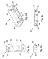
- Figs. 1a, 1b, 1c, and 1d are, respectively, top plan, end elevational, front elevational, and perspective views of a sample plate embodying the features of the invention
- Figs. 2a, 2b, 2c, and 2d are, respectively, top plan, end elevational, front elevational, and perspective views of a manifold embodying the features of the invention.
- Figs. 3a, 3b, 3c, and 3d are, respectively, end elevational, top plan, and front elevational views of a base plate embodying the features of the invention.
- the system includes two main components; namely, moveable sample plates to which a container to be tested is affixed; and an associated manifold system.
- a bushing shown in Fig. 1 d is adapted to receive pins of an associated manifold 30 shown in Fig. 2d .
- the elements may be suitably affixed to the base plate 50 shown in Figs. 3a, 3b, and 3c by threaded fasteners, for example.
- the sample plate 10 comprises a main body 12 having an annular recess 14 for receiving the neck or finish of a plastic container to be tested.
- the recess 14 is defined by an annular shoulder 16.
- a coaxial recess 18 is formed centrally of the annular shoulder 16.
- the open end of the recess 18 is defined by an upstanding annular 20.
- a conduit 22 is formed in the main body 12 to provide communication between a source of pressure fluid and the interior of the container being tested.
- Another conduit 24 is formed in the main body 12 to provide communication with a return of the pressure fluid introduced through the conduit 22.
- a pair of spaced apart bushings 26, 28 is formed to extend inwardly of the main body 12 and receive cooperating locating pins, as will be explained hereinafter.
- Figs. 2a, 2b, 2c, and 2d illustrate a manifold 30 which comprises a main body 32 having at least one conduit 34 to communicate with the inlet of the sample plate conduit 22 and a conduit 36 communicating with the sample plate conduit 24, and coupling means including pins 38, 39 for selectively coupling the sample plate 10 and the manifold 30.
- Grooves may be circumscribed around the inlets and outlets of conduits of the sample plate 10 and the manifold 30 to retain seals.
- the seals are utilized to close the system when the sample plate 10 is in operative position.
- the grooves circumscribed around the conduits are preferably grooves adapted to retain o-ring seals.
- any suitable means of selectively coupling the sample plate 10 and manifold 30 may be used. It has been found that satisfactory results may be achieved by utilizing the spaced apart inwardly extending bushing 26, 28 in the sample plate 10 to receive the corresponding respective pins 38, 39 of the manifold 30. Manifold mold-style pins 38, 39 as shown in Fig. 2d ensure proper alignment with sample plate mold-style bushings 26, 28 as shown in Fig. 1d .
- the manifold 30 can be mounted to a base plate 50 as illustrated in Figs. 3a, 3b, and 3c .
- the base plate 50 serves as a support for the entire system.
- the manifold 30 is provided with spaced apart passageways or holes 40, 42 to receive suitable threaded fasteners. The threaded ends of such fasteners are threadably received within internally threaded holes 52, 53, respectively of the base plate 50 to assure proper alignment.
- a pair of spaced apart passageways or holes is formed in the base plate 50 to allow the passage of conduits communicating with the manifold conduits 34, 36.
- the base plate 50 is adapted to accommodate a pair of manifolds 30.
- the pair of manifolds may be formed separately or may be formed as one integral unit.
- the sample plates 10 which are used with the pair of manifolds 30 may also be formed separately or as one integral unit.
- the sample plate 10 is connected with the manifold 30.
- the connection may be tightened to urge the sample plate 10 against o-rings in the manifold 30. Compression of the sample plate 10 against the o-rings closes the conduit-container-manifold system.
- the sample plate 10, manifold 30, and base plate 50 are preferably constructed of aluminum or other lightweight durable alloy. Lightweight components are desired for easier portability of system components and to allow rapid exchange of sample plates during testing. However, the components of the system may be constructed of any appropriate material that withstand system temperature, pressure, and use requirements.
- the testing of a container typically involves the following steps. First, a container is placed on and secured to the mounting area of a sample plate 10 with an epoxy resin or other suitable adhesive material. The sample plate 10 is selectively coupled to the manifold 30 which is already attached to the base plate 50. The sample plate 10 is securely compressed against the o-rings of the manifold 30 to close the system. Compression occurs by tightening the connection between the sample plate 10 and the manifold 30 by any means, such as by clamping, for example.
- the pressure fluid is allowed to flow through into the container through the manifold conduit 34 and the sample plate conduit 22.
- the pressure fluid is pure nitrogen.
- a system described above for testing a container may also be used to test permeation characteristics of other materials, such as a film for example.
- the film is disposed on an open-ended container (not shown) and sealed or otherwise connected to the container so the flow of fluid around the film into the container is militated against.
- the sample plate conduits 22, 24 described above are in communication with the container.
- the pressure fluid is introduced into the container and exposed to the inner side of the film.
- the outer side of the film is exposed to atmosphere or a controlled environment. Gas which permeates through the film is picked up by the pressure fluid and tested to determine the permeation characteristics of the film.
Landscapes
- Physics & Mathematics (AREA)
- General Physics & Mathematics (AREA)
- Chemical & Material Sciences (AREA)
- Dispersion Chemistry (AREA)
- Health & Medical Sciences (AREA)
- Life Sciences & Earth Sciences (AREA)
- Analytical Chemistry (AREA)
- Biochemistry (AREA)
- General Health & Medical Sciences (AREA)
- Immunology (AREA)
- Pathology (AREA)
- Examining Or Testing Airtightness (AREA)
- Sampling And Sample Adjustment (AREA)
Description
- Field of the Invention: The present invention relates to a container testing apparatus. More particularly, the present invention relates to a system for measuring gas permeation through plastic container walls.
- Description of the Prior Art: In the preservation of beverages which are liable to be affected by oxidation, there is a problem that the beverages are oxidized by a small amount of oxygen present in a container used for storage. Therefore, it is of paramount importance to ascertain the oxygen permeation characteristics of the plastic containers to be used for the beverage storage. In the prior art, the systems for testing oxygen permeation require that each time a container is placed on or removed from a system for gas permeation testing, the containers to be tested must be affixed onto flat plates which have soldered connections that must be screwed onto a mating fitting of an associated manifold. Frequently, testing errors result, primarily from minute leakage around the fittings and components. Problems further increase with repeated use of the fittings.
- One solution is to replace the fittings more often and to more meticulously affix the container to the flat plates to ensure a better connection. However, these options significantly increase the amount of time between testing of containers while still allowing for testing errors.
- Those skilled in the art have continued to search for the solution of how to provide a practical testing system.
US-A-3850040 Orr et al. , discloses a method and apparatus for sorption analysis.
FR-A-2308100 Lyssy
US-B1-6,964,191 Murthy , discloses apparatus and technique for measuring permeability and permeant sorption.
US 2007 215046, Lupeke et al , discloses a method for determining the gas permeability of container walls, container provided with a surface coating, and coating device comprising a measuring element.
US 2004 040372, Plester et al , discloses a method for determining the permeation of gases into or out of plastic packages and for determination of shelf-life with respect to gas permeation - In order to solve the problem longstanding in the art, a simplified and improved system for mounting and connecting materials and containers for permeation testing has been surprisingly provided.
- In one embodiment of the present invention, the system is constructed of two main components; namely, moveable sample plates to which the containers are affixed, and a permanently mounted manifold.
- The aforementioned sample plate is provided with three components; namely, a support for a container to be tested; conduits through which a gas may flow; and bushings to ensure proper alignment of the sample plate with the manifold.
- The manifold is provided with three components; namely, pins to ensure proper alignment with the bushings of the sample plate; conduits through which a gas may flow to and from the container during testing; and grooves around the conduits which retain seals.
- It is an object of the present invention to produce a system for measuring gas permeation through a plastic material of the type employed for producing plastic containers.
- It is a further object of the present invention to eliminate screw-type tubing connections from the system to allow for faster removal and exchange of samples for testing.
- It is still a further object still a further object of the present invention to decrease the time required to conduct the testing procedures.
- Still another object another object of the invention is to improve the reliability of the seal between the sample plate and container by constructing a mounting plate with a pocket that the container fits into before being attached with a suitable adhesive material.
- Further objects and advantages of the invention will be apparent from the following description and appended claims, reference being made to the accompanying drawings forming a part of the specification.
- Other objects and advantages of the invention will become readily apparent to those skilled in the art from reading the following description of the invention when considered in the light of the accompanying drawings, in which:
-
Figs. 1a, 1b, 1c, and 1d are, respectively, top plan, end elevational, front elevational, and perspective views of a sample plate embodying the features of the invention; -
Figs. 2a, 2b, 2c, and 2d are, respectively, top plan, end elevational, front elevational, and perspective views of a manifold embodying the features of the invention; and -
Figs. 3a, 3b, 3c, and 3d are, respectively, end elevational, top plan, and front elevational views of a base plate embodying the features of the invention. - It is to be understood that the present invention is not limited in its application to the details of construction and arrangement of parts illustrated in the accompanying drawings, since the invention is capable of other embodiments, and of being practiced or carried out in various ways within the scope of the appended claims. Also, it is to be understood that the phraseology and terminology employed herein is for the purpose of description, and not of limitation.
- Referring to the accompanying drawings, there is shown components of a system for mounting and connecting plastic material, such as used in containers for permeation testing which embody the features of the invention.
- The system includes two main components; namely, moveable sample plates to which a container to be tested is affixed; and an associated manifold system.
- A bushing shown in
Fig. 1 d is adapted to receive pins of an associatedmanifold 30 shown inFig. 2d . The elements may be suitably affixed to thebase plate 50 shown inFigs. 3a, 3b, and 3c by threaded fasteners, for example. - The
sample plate 10 comprises amain body 12 having anannular recess 14 for receiving the neck or finish of a plastic container to be tested. Therecess 14 is defined by anannular shoulder 16. Acoaxial recess 18 is formed centrally of theannular shoulder 16. The open end of therecess 18 is defined by an upstanding annular 20. Aconduit 22 is formed in themain body 12 to provide communication between a source of pressure fluid and the interior of the container being tested. - Another
conduit 24 is formed in themain body 12 to provide communication with a return of the pressure fluid introduced through theconduit 22. A pair of spaced apartbushings main body 12 and receive cooperating locating pins, as will be explained hereinafter. -
Figs. 2a, 2b, 2c, and 2d illustrate amanifold 30 which comprises amain body 32 having at least oneconduit 34 to communicate with the inlet of thesample plate conduit 22 and aconduit 36 communicating with thesample plate conduit 24, and coupling means includingpins sample plate 10 and themanifold 30. - Grooves may be circumscribed around the inlets and outlets of conduits of the
sample plate 10 and themanifold 30 to retain seals. The seals are utilized to close the system when thesample plate 10 is in operative position. The grooves circumscribed around the conduits are preferably grooves adapted to retain o-ring seals. - Any suitable means of selectively coupling the
sample plate 10 andmanifold 30 may be used. It has been found that satisfactory results may be achieved by utilizing the spaced apart inwardly extending bushing 26, 28 in thesample plate 10 to receive the correspondingrespective pins manifold 30. Manifold mold-style pins Fig. 2d ensure proper alignment with sample plate mold-style bushings Fig. 1d . - The
manifold 30 can be mounted to abase plate 50 as illustrated inFigs. 3a, 3b, and 3c . Thebase plate 50 serves as a support for the entire system. Themanifold 30 is provided with spaced apart passageways orholes holes base plate 50 to assure proper alignment. A pair of spaced apart passageways or holes is formed in thebase plate 50 to allow the passage of conduits communicating with themanifold conduits base plate 50 is adapted to accommodate a pair ofmanifolds 30. The pair of manifolds may be formed separately or may be formed as one integral unit. Thesample plates 10 which are used with the pair ofmanifolds 30 may also be formed separately or as one integral unit. - Once aligned, the
sample plate 10 is connected with the manifold 30. The connection may be tightened to urge thesample plate 10 against o-rings in themanifold 30. Compression of thesample plate 10 against the o-rings closes the conduit-container-manifold system. - The
sample plate 10,manifold 30, andbase plate 50 are preferably constructed of aluminum or other lightweight durable alloy. Lightweight components are desired for easier portability of system components and to allow rapid exchange of sample plates during testing. However, the components of the system may be constructed of any appropriate material that withstand system temperature, pressure, and use requirements. - The testing of a container typically involves the following steps. First, a container is placed on and secured to the mounting area of a
sample plate 10 with an epoxy resin or other suitable adhesive material. Thesample plate 10 is selectively coupled to the manifold 30 which is already attached to thebase plate 50. Thesample plate 10 is securely compressed against the o-rings of the manifold 30 to close the system. Compression occurs by tightening the connection between thesample plate 10 and the manifold 30 by any means, such as by clamping, for example. - Once the system is closed, the pressure fluid is allowed to flow through into the container through the
manifold conduit 34 and thesample plate conduit 22. Favorable results have been found wherein the pressure fluid is pure nitrogen. Once the pressure fluid is introduced into the container, it flows out of the container through thesample plate conduit 24 and themanifold conduit 36. Any gas which permeated through the container will also flow out of the container through thesample plate conduit 24 and themanifold conduit 36 to the testing sensor. - A system described above for testing a container may also be used to test permeation characteristics of other materials, such as a film for example. In this situation, the film is disposed on an open-ended container (not shown) and sealed or otherwise connected to the container so the flow of fluid around the film into the container is militated against. The
sample plate conduits
Claims (11)
- A system for gas permeation testing of plastic containers comprising:a manifold (30) having a body, the body having a first manifold conduit (34) in fluid communication with a source of pressure fluid and a second manifold conduit (36) in fluid communication with a testing sensor, characterised bya sample plate (10) for receiving a container selectively attached to said manifold, said sample plate having a first conduit (22) in fluid communication with the first manifold conduit (34) providing fluid communication between the source of pressure fluid and an interior of the container and a second conduit (24) in fluid communication with the second manifold conduit (36) providing fluid communication between the interior of the container and the testing sensor.
- The system for gas permeation testing in accordance with Claim 1, wherein said sample plate includes a recess formed thereon for receiving the container to be tested.
- The system for gas permeation testing in accordance with any preceding claim, wherein said sample plate includes a second recess formed thereon centrally from the recess for receiving the container to be tested.
- The system for gas permeation testing in accordance with any preceding claim, further including an adhesive disposed in the recess adapted to secure the container to said sample plate.
- The system for gas permeation testing in accordance with Claim 4, wherein the adhesive is an epoxy resin.
- The system for gas permeation testing in accordance with any preceding claim, wherein said manifold is adapted to be removably mounted to a base plate.
- The system for gas permeation testing in accordance with any preceding claim, wherein said manifold includes a pair of spaced apart pins which are received by a pair of spaced apart bushings formed in said sample plate.
- The system for gas permeation testing in accordance with Claim 7, wherein a groove adapted to receive a seal is formed around each of the spaced apart pins.
- The system for gas permeation testing in accordance with Claim 8, wherein a groove adapted to receive a seal is formed around each of the spaced apart bushings.
- The system for gas permeation testing in accordance with Claims 8 or 9, wherein the seal is an o-ring.
- The system for gas permeation testing in accordance with any preceding claim wherein the sample plate includes a container for recovering all materials to be tested.
Applications Claiming Priority (2)
| Application Number | Priority Date | Filing Date | Title |
|---|---|---|---|
| US72227805P | 2005-09-30 | 2005-09-30 | |
| PCT/US2006/038226 WO2007041385A2 (en) | 2005-09-30 | 2006-09-29 | System for gas permeation testing |
Publications (3)
| Publication Number | Publication Date |
|---|---|
| EP1929272A2 EP1929272A2 (en) | 2008-06-11 |
| EP1929272A4 EP1929272A4 (en) | 2009-04-22 |
| EP1929272B1 true EP1929272B1 (en) | 2013-07-17 |
Family
ID=37906755
Family Applications (1)
| Application Number | Title | Priority Date | Filing Date |
|---|---|---|---|
| EP06815895.5A Not-in-force EP1929272B1 (en) | 2005-09-30 | 2006-09-29 | System for gas permeation testing |
Country Status (7)
| Country | Link |
|---|---|
| US (1) | US7752888B2 (en) |
| EP (1) | EP1929272B1 (en) |
| JP (1) | JP2009510452A (en) |
| AU (1) | AU2006299632B2 (en) |
| BR (1) | BRPI0616396A2 (en) |
| CA (1) | CA2623440A1 (en) |
| WO (1) | WO2007041385A2 (en) |
Families Citing this family (1)
| Publication number | Priority date | Publication date | Assignee | Title |
|---|---|---|---|---|
| CA2693263A1 (en) * | 2007-07-19 | 2009-01-22 | Frank E. Semersky | Gas permeation testing system |
Family Cites Families (33)
| Publication number | Priority date | Publication date | Assignee | Title |
|---|---|---|---|---|
| US3348395A (en) * | 1963-12-06 | 1967-10-24 | Georgia Tech Res Inst | Specimen mounting device for porosity determination apparatus |
| US3248930A (en) * | 1965-03-26 | 1966-05-03 | Halliburton Co | Apparatus for testing the permeability of materials |
| US3494175A (en) * | 1968-09-05 | 1970-02-10 | Us Navy | Pressure commutator mode switch |
| AU449169B2 (en) * | 1968-10-23 | 1974-05-16 | Owens-Illinois, Inc | Leak detector |
| US3590634A (en) * | 1969-05-05 | 1971-07-06 | Stanford Research Inst | Instrument for determining permeation rates through a membrane |
| US3729983A (en) * | 1970-08-27 | 1973-05-01 | Inland Steel Co | Leak tightness testing method and apparatus |
| US3751973A (en) * | 1971-02-08 | 1973-08-14 | Glass Containers Corp | Apparatus and method for pressure testing containers |
| US3805594A (en) * | 1971-10-19 | 1974-04-23 | Mitsubishi Heavy Ind Ltd | Pressure testing apparatus for bottles |
| US3850040A (en) | 1972-08-17 | 1974-11-26 | Micromeritics Instr Corp | Sorption analysis apparatus and method |
| CH590467A5 (en) * | 1975-04-18 | 1977-08-15 | Lyssy Georges H | |
| US4511044A (en) * | 1982-02-24 | 1985-04-16 | The West Company | Seal force monitor apparatus, system, and method for in-process determination of integrity of sealed containers |
| US4459843A (en) * | 1982-07-06 | 1984-07-17 | Durham La Moyne W | Apparatus and method for testing containers |
| JPH0454444Y2 (en) * | 1985-03-12 | 1992-12-21 | ||
| US4914810A (en) * | 1985-12-02 | 1990-04-10 | Carrier Corporation | Apparatus for measuring the pore size of enhanced tubes |
| US4747298A (en) * | 1986-12-04 | 1988-05-31 | Mcdaniel Patrick K | Container leak detector |
| US4788850A (en) * | 1987-04-06 | 1988-12-06 | Five X Corporation | Bottle testing apparatus |
| US5001935A (en) * | 1990-02-27 | 1991-03-26 | Hoover Universal, Inc. | Method and apparatus for determining the environmental stress crack resistance of plastic articles |
| JPH10267826A (en) * | 1997-03-27 | 1998-10-09 | Dainippon Printing Co Ltd | Jig and method for measuring gas permeability of container |
| US6013026A (en) * | 1999-02-25 | 2000-01-11 | Welch Allyn, Inc. | Releasable laryngeal blade assembly and set of laryngoscopes |
| DE19962303A1 (en) * | 1999-12-23 | 2001-07-12 | Gebele Thomas | Method for determining the barrier property of a container for all gases |
| AUPQ788000A0 (en) * | 2000-05-30 | 2000-06-22 | Structural Monitoring Systems Ltd | Apparatus and method for measurement of the permeability of materials |
| AU2002213242A1 (en) * | 2000-10-17 | 2002-04-29 | Ball Corporation | Shelf life testing unit |
| JP2002310843A (en) * | 2001-04-12 | 2002-10-23 | Mitsubishi Plastics Ind Ltd | Container leak test method |
| US6598463B2 (en) * | 2001-05-02 | 2003-07-29 | Du Pont | Method for determining gas accumulation rates |
| US6817238B2 (en) * | 2001-06-22 | 2004-11-16 | Bj Services Company | Cement expansion/contraction test apparatus |
| KR20050007341A (en) * | 2002-04-26 | 2005-01-17 | 호카이세이칸가부시끼가이샤 | Plastic containers coated on the inner surface and process for production thereof |
| US20040040372A1 (en) * | 2002-08-30 | 2004-03-04 | George Plester | Method for determining the permeation of gases into or out of plastic packages and for determination of shelf-life with respect to gas permeation |
| US6964191B1 (en) * | 2002-10-15 | 2005-11-15 | Murthy Tata | Apparatus and technique for measuring permeability and permeant sorption |
| JP2004279281A (en) * | 2003-03-17 | 2004-10-07 | Takeshi Kage | Gas barrier property measurement method for plastic molded articles |
| JP4232548B2 (en) * | 2003-06-19 | 2009-03-04 | 東洋製罐株式会社 | Gas barrier performance measuring method and measuring apparatus |
| CA2473293A1 (en) * | 2003-07-07 | 2005-01-07 | Porotech Ltd. | Porosimetric device |
| DE10354625A1 (en) * | 2003-11-22 | 2005-06-30 | Sig Technology Ltd. | Method for determining the gas permeability of container walls, containers with surface coating and coating device with measuring device |
| FR2895510B1 (en) * | 2005-12-22 | 2008-03-28 | Sidel Sas | DEVICE FOR MEASURING PERMEATION OF A HOLLOW BODY SUCH AS A CONTAINER |
-
2006
- 2006-09-29 JP JP2008533716A patent/JP2009510452A/en active Pending
- 2006-09-29 EP EP06815895.5A patent/EP1929272B1/en not_active Not-in-force
- 2006-09-29 AU AU2006299632A patent/AU2006299632B2/en not_active Ceased
- 2006-09-29 US US11/575,459 patent/US7752888B2/en active Active
- 2006-09-29 WO PCT/US2006/038226 patent/WO2007041385A2/en not_active Ceased
- 2006-09-29 CA CA002623440A patent/CA2623440A1/en not_active Abandoned
- 2006-09-29 BR BRPI0616396-3A patent/BRPI0616396A2/en not_active IP Right Cessation
Also Published As
| Publication number | Publication date |
|---|---|
| EP1929272A2 (en) | 2008-06-11 |
| CA2623440A1 (en) | 2007-04-12 |
| BRPI0616396A2 (en) | 2011-06-21 |
| US7752888B2 (en) | 2010-07-13 |
| WO2007041385A2 (en) | 2007-04-12 |
| AU2006299632B2 (en) | 2011-06-02 |
| EP1929272A4 (en) | 2009-04-22 |
| US20090229347A1 (en) | 2009-09-17 |
| AU2006299632A1 (en) | 2007-04-12 |
| WO2007041385A3 (en) | 2008-09-18 |
| JP2009510452A (en) | 2009-03-12 |
Similar Documents
| Publication | Publication Date | Title |
|---|---|---|
| US12521713B2 (en) | Method and apparatus to identify fluidic path positions | |
| US8327688B2 (en) | Gas permeation testing system | |
| JP2003035622A (en) | Work leak inspection device, chamber for leak inspection device, and leak inspection method | |
| CA2100739C (en) | Leakage measurement into a gas-charged container | |
| US4495795A (en) | Permeameter | |
| US7752888B2 (en) | System for gas permeation testing | |
| CN219758022U (en) | Hydrogen permeability testing device for solid detection material | |
| JP2016223924A (en) | Method and device for measuring gas permeation amount | |
| CN116242553A (en) | Preparation method and test method of leakage sample of high-pressure gas cylinder | |
| JP2010503848A (en) | Method for measuring gas permeability of container and sealing member | |
| US6347545B1 (en) | Closure pressure testing apparatus and method for testing closures | |
| US8950242B1 (en) | Testing hoses at increased pressure vessels | |
| KR20110122479A (en) | Liquid vacuum filling bag, liquid vacuum filling device and liquid vacuum filling method | |
| US20250333291A1 (en) | Device for the pressure testing, evacuation and filling of an assembly | |
| US20240091780A1 (en) | Analyte permeation testing instrument with test sample peripheral edge sealing surround | |
| US3306097A (en) | Apparatus for testing cans | |
| JP3096609U (en) | Thin film transmission measurement cell, thin film transmission measurement device | |
| CN220650402U (en) | Portable bubbling point testing device | |
| JP2006308394A (en) | Gas permeability measurement method, purging device for gas permeability measurement, and gas permeability measurement system | |
| TW201627644A (en) | Air tightness testing device | |
| CN221350201U (en) | True volume testing device | |
| EP4386357A1 (en) | Capture vessel cartridge for permeation testing of prefilled packages and containers | |
| JPS5842924Y2 (en) | Corrosion test equipment for tubular materials | |
| JP4644023B2 (en) | Dilution device | |
| CN117705352A (en) | Integrated device and method for verifying sensitivity of vacuum leakage detection |
Legal Events
| Date | Code | Title | Description |
|---|---|---|---|
| PUAI | Public reference made under article 153(3) epc to a published international application that has entered the european phase |
Free format text: ORIGINAL CODE: 0009012 |
|
| 17P | Request for examination filed |
Effective date: 20080328 |
|
| AK | Designated contracting states |
Kind code of ref document: A2 Designated state(s): AT BE BG CH CY CZ DE DK EE ES FI FR GB GR HU IE IS IT LI LT LU LV MC NL PL PT RO SE SI SK TR |
|
| AX | Request for extension of the european patent |
Extension state: AL BA HR MK RS |
|
| R17D | Deferred search report published (corrected) |
Effective date: 20080918 |
|
| A4 | Supplementary search report drawn up and despatched |
Effective date: 20090323 |
|
| 17Q | First examination report despatched |
Effective date: 20090814 |
|
| RBV | Designated contracting states (corrected) |
Designated state(s): DE FR GB |
|
| DAX | Request for extension of the european patent (deleted) | ||
| GRAP | Despatch of communication of intention to grant a patent |
Free format text: ORIGINAL CODE: EPIDOSNIGR1 |
|
| GRAS | Grant fee paid |
Free format text: ORIGINAL CODE: EPIDOSNIGR3 |
|
| GRAA | (expected) grant |
Free format text: ORIGINAL CODE: 0009210 |
|
| AK | Designated contracting states |
Kind code of ref document: B1 Designated state(s): DE FR GB |
|
| REG | Reference to a national code |
Ref country code: GB Ref legal event code: FG4D |
|
| REG | Reference to a national code |
Ref country code: DE Ref legal event code: R096 Ref document number: 602006037413 Country of ref document: DE Effective date: 20130912 |
|
| PLBE | No opposition filed within time limit |
Free format text: ORIGINAL CODE: 0009261 |
|
| STAA | Information on the status of an ep patent application or granted ep patent |
Free format text: STATUS: NO OPPOSITION FILED WITHIN TIME LIMIT |
|
| 26N | No opposition filed |
Effective date: 20140422 |
|
| REG | Reference to a national code |
Ref country code: DE Ref legal event code: R097 Ref document number: 602006037413 Country of ref document: DE Effective date: 20140422 |
|
| REG | Reference to a national code |
Ref country code: DE Ref legal event code: R082 Ref document number: 602006037413 Country of ref document: DE Representative=s name: FRIESE GOEDEN PATENTANWAELTE PARTGMBB, DE Ref country code: DE Ref legal event code: R082 Ref document number: 602006037413 Country of ref document: DE Representative=s name: ANDRAE WESTENDORP PATENTANWAELTE PARTNERSCHAFT, DE |
|
| REG | Reference to a national code |
Ref country code: FR Ref legal event code: PLFP Year of fee payment: 10 |
|
| PGFP | Annual fee paid to national office [announced via postgrant information from national office to epo] |
Ref country code: GB Payment date: 20150923 Year of fee payment: 10 Ref country code: DE Payment date: 20150922 Year of fee payment: 10 |
|
| PGFP | Annual fee paid to national office [announced via postgrant information from national office to epo] |
Ref country code: FR Payment date: 20150908 Year of fee payment: 10 |
|
| REG | Reference to a national code |
Ref country code: DE Ref legal event code: R082 Ref document number: 602006037413 Country of ref document: DE Representative=s name: FRIESE GOEDEN PATENTANWAELTE PARTGMBB, DE |
|
| REG | Reference to a national code |
Ref country code: DE Ref legal event code: R119 Ref document number: 602006037413 Country of ref document: DE |
|
| GBPC | Gb: european patent ceased through non-payment of renewal fee |
Effective date: 20160929 |
|
| REG | Reference to a national code |
Ref country code: FR Ref legal event code: ST Effective date: 20170531 |
|
| PG25 | Lapsed in a contracting state [announced via postgrant information from national office to epo] |
Ref country code: FR Free format text: LAPSE BECAUSE OF NON-PAYMENT OF DUE FEES Effective date: 20160930 Ref country code: DE Free format text: LAPSE BECAUSE OF NON-PAYMENT OF DUE FEES Effective date: 20170401 Ref country code: GB Free format text: LAPSE BECAUSE OF NON-PAYMENT OF DUE FEES Effective date: 20160929 |