EP1928048A1 - Direct-flame fuel cell - Google Patents
Direct-flame fuel cell Download PDFInfo
- Publication number
- EP1928048A1 EP1928048A1 EP07023379A EP07023379A EP1928048A1 EP 1928048 A1 EP1928048 A1 EP 1928048A1 EP 07023379 A EP07023379 A EP 07023379A EP 07023379 A EP07023379 A EP 07023379A EP 1928048 A1 EP1928048 A1 EP 1928048A1
- Authority
- EP
- European Patent Office
- Prior art keywords
- fuel cell
- anode
- direct
- flame
- metal compounds
- Prior art date
- Legal status (The legal status is an assumption and is not a legal conclusion. Google has not performed a legal analysis and makes no representation as to the accuracy of the status listed.)
- Granted
Links
Images


Classifications
-
- H—ELECTRICITY
- H01—ELECTRIC ELEMENTS
- H01M—PROCESSES OR MEANS, e.g. BATTERIES, FOR THE DIRECT CONVERSION OF CHEMICAL ENERGY INTO ELECTRICAL ENERGY
- H01M4/00—Electrodes
- H01M4/86—Inert electrodes with catalytic activity, e.g. for fuel cells
- H01M4/90—Selection of catalytic material
- H01M4/9016—Oxides, hydroxides or oxygenated metallic salts
-
- H—ELECTRICITY
- H01—ELECTRIC ELEMENTS
- H01M—PROCESSES OR MEANS, e.g. BATTERIES, FOR THE DIRECT CONVERSION OF CHEMICAL ENERGY INTO ELECTRICAL ENERGY
- H01M4/00—Electrodes
- H01M4/86—Inert electrodes with catalytic activity, e.g. for fuel cells
- H01M4/8605—Porous electrodes
- H01M4/8621—Porous electrodes containing only metallic or ceramic material, e.g. made by sintering or sputtering
-
- H—ELECTRICITY
- H01—ELECTRIC ELEMENTS
- H01M—PROCESSES OR MEANS, e.g. BATTERIES, FOR THE DIRECT CONVERSION OF CHEMICAL ENERGY INTO ELECTRICAL ENERGY
- H01M4/00—Electrodes
- H01M4/86—Inert electrodes with catalytic activity, e.g. for fuel cells
- H01M4/88—Processes of manufacture
- H01M4/8878—Treatment steps after deposition of the catalytic active composition or after shaping of the electrode being free-standing body
- H01M4/8882—Heat treatment, e.g. drying, baking
- H01M4/8885—Sintering or firing
-
- H—ELECTRICITY
- H01—ELECTRIC ELEMENTS
- H01M—PROCESSES OR MEANS, e.g. BATTERIES, FOR THE DIRECT CONVERSION OF CHEMICAL ENERGY INTO ELECTRICAL ENERGY
- H01M4/00—Electrodes
- H01M4/86—Inert electrodes with catalytic activity, e.g. for fuel cells
- H01M2004/8678—Inert electrodes with catalytic activity, e.g. for fuel cells characterised by the polarity
- H01M2004/8684—Negative electrodes
-
- H—ELECTRICITY
- H01—ELECTRIC ELEMENTS
- H01M—PROCESSES OR MEANS, e.g. BATTERIES, FOR THE DIRECT CONVERSION OF CHEMICAL ENERGY INTO ELECTRICAL ENERGY
- H01M8/00—Fuel cells; Manufacture thereof
- H01M8/10—Fuel cells with solid electrolytes
- H01M8/12—Fuel cells with solid electrolytes operating at high temperature, e.g. with stabilised ZrO2 electrolyte
- H01M2008/1293—Fuel cells with solid oxide electrolytes
-
- H—ELECTRICITY
- H01—ELECTRIC ELEMENTS
- H01M—PROCESSES OR MEANS, e.g. BATTERIES, FOR THE DIRECT CONVERSION OF CHEMICAL ENERGY INTO ELECTRICAL ENERGY
- H01M4/00—Electrodes
- H01M4/86—Inert electrodes with catalytic activity, e.g. for fuel cells
- H01M4/90—Selection of catalytic material
- H01M4/9041—Metals or alloys
- H01M4/905—Metals or alloys specially used in fuel cell operating at high temperature, e.g. SOFC
- H01M4/9066—Metals or alloys specially used in fuel cell operating at high temperature, e.g. SOFC of metal-ceramic composites or mixtures, e.g. cermets
-
- Y—GENERAL TAGGING OF NEW TECHNOLOGICAL DEVELOPMENTS; GENERAL TAGGING OF CROSS-SECTIONAL TECHNOLOGIES SPANNING OVER SEVERAL SECTIONS OF THE IPC; TECHNICAL SUBJECTS COVERED BY FORMER USPC CROSS-REFERENCE ART COLLECTIONS [XRACs] AND DIGESTS
- Y02—TECHNOLOGIES OR APPLICATIONS FOR MITIGATION OR ADAPTATION AGAINST CLIMATE CHANGE
- Y02E—REDUCTION OF GREENHOUSE GAS [GHG] EMISSIONS, RELATED TO ENERGY GENERATION, TRANSMISSION OR DISTRIBUTION
- Y02E60/00—Enabling technologies; Technologies with a potential or indirect contribution to GHG emissions mitigation
- Y02E60/30—Hydrogen technology
- Y02E60/50—Fuel cells
Definitions
- the present invention relates to a direct-flame fiel cell, in particular to a direct-flame fuel cell which uses a cell that is configured in such a manner that a solid electrolyte is sandwiched between an anode and a cathode.
- a direct-flame fuel cell in which power is generated by placing a cell inside or in the vicinity of a flame and thereby exposing the anode side to the flame, the cell being configured in such a manner that a solid electrolyte is sandwiched between an anode and a cathode.
- This type of direct-flame fuel cell is disclosed in Patent document JP-A-2004-139936 , for example.
- the direct-flame fuel cell can generate power in a simple and easy way and enables miniaturization of a fuel cell module in which cells are combined as desired. Furthermore, with a high degree of freedom of fuel selection, it is expected that the direct-flame fuel cell will be applied to various uses.
- the surface of the anode of the cell is directly exposed to a flame during power generation, a large amount of soot is attached to the anode depending on the time of exposure to the flame.
- the soot that is attached to the anode is a cause of deteriorating the power generation performance of the cell to a large extent over time.
- An object of the present invention is to provide a direct-flame fuel cell which suppresses deterioration of the power generation performance of a cell by lowering the degree of attachment of soot to the anode.
- a direct-flame fuel cell including:
- the attachment of soot to the anode is suppressed by the function of the one or more kinds of alkaline metal compounds or alkaline earth metal compounds, whereby the deterioration of the power generation performance of the cell can be suppressed.
- the invention can thus provide a direct-flame fuel cell having a long life.
- Rh 2 O 3 which is added as an oxidation catalyst exhibits an effect of suppressing soot generation.
- a cell is prepared in which, as shown in Fig.
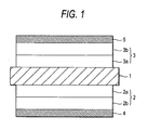
- an anode 2 having a two-layer structure formed by an inner anode layer 2a made of SDC (60 wt%)-Ni 0.9 Co 0.1 O and an outer anode layer 2b which is made of SDC (30 wt%)-Ni 0.9 Co 0.1 O added with Rh 2 O 3 (5 wt%)) is provided on one side of a solid electrolyte 1 made of samaria-doped ceria (SDC) and a cathode 3 having a two-layer structure (formed by an inner cathode layer 3a made of SDC (50 wt%)-SSC and an outer cathode layer 3b made of a cathode material of SDC (30 wt%) -SSC added with a pore-forming material (55 vol%)) is provided on the other side of the solid electrolyte 1.
- SDC samaria-doped ceria
- collectors 4 and 5 each of which is a platinum mesh are connected to the outer anode layer 2b and the outer cathode layer 3b, respectively of the cell of Fig. 1 .
- a comparative cell is prepared which had the same two-layer anode and cathode as the cell of Fig. 1 except that the outer anode layer does not contain Rh 2 O 3 .
- Each of the above cells is caused to generate power at a constant current (400 mA/cm 2 ) while being exposed to a flame of a Bunsen burner to which a fuel-air mixture gas containing n-butane (6.5%), and a variation of the output power with time is observed.
- Figs. 2 and 3 show results of the comparative cell and the cell using the outer anode layer 2b that is added with Rh 2 O 3 , respectively.
- soot is generated remarkably immediately after the start of power generation and the output power decreased steeply.
- output power reduction due to soot generation is observed after a lapse of about 20 hours.
- the inventors have found that compounds of alkaline earth metals such as calcium, barium, and strontium and compounds of alkaline metals such as sodium, potassium, and cesium are effective in suppressing soot generation by studying the soot generation suppressing effect (like the one Rh 2 O 3 exhibits) of various substances, and have completed the invention on the basis of this fact.
- alkaline earth metal compounds are carbonates, oxides, hydroxides, nitrates, and sulfates of calcium, barium, and strontium.
- Typical examples of such alkaline metal compounds are carbonates, oxides, hydroxides, nitrates, and sulfates of sodium, potassium, and cesium.
- a mixture of alkaline metal compounds, a mixture of alkaline earth metal compounds, or a mixture of an alkaline metal compound and an alkaline earth metal compound may also be used.
- Figs. 5A to 5C are photographs, taken after power generation of 15 hours, of the anode surfaces of sample 1 using an outer anode layer in which neither Rh 2 O 3 nor CaCO 3 is added, sample 2 using an outer anode layer in which only Rh 2 O 3 is added, and sample 3 using an outer anode layer in which both of Rh 2 O 3 and CaCO 3 are added. It is seen that soot is attached to the entire surface of the anode in sample 1 ( Fig. 5A ; neither Rh 2 O 3 nor CaCO 3 is added) and the degree of attachment of soot is lower in sample 2 ( Fig. 5B ; only Rh 2 O 3 is added) than in sample 1. Almost no soot is attached to the anode in sample 3 ( Fig. 5C ; both of Rh 2 O 3 and CaCO 3 are added). The same test is performed on a sample in which only CaCO 3 is added to produce a result that is the same as of sample 3.
- the anode of the fuel cell according to the invention is not limited to the above-described one having a two-layer structure, and may have a multilayer structure of three or more layers or a single-layer structure (described later). In each case, it is important that the alkaline metal compound or the alkaline earth metal compound (essentially a non-conductive substance) which is effective in suppressing soot generation due to exposure to a flame be added in the outermost layer of the cell that is directly exposed to a flame.
- CaCO 3 be added at 1 to 10 wt% with respect to the amount of the anode materials irrespective of whether the anode contains Rh 2 O 3 . If the addition amount of CaCO 3 is smaller than 1 wt%, the effect of suppressing soot generation is slight. If it is larger than 10 wt%, output power reduction starts earlier contrary to the intention. In the case of a multi-layered anode, the amount of the compound such as CaCO 3 that is effective in suppressing soot generation is that in the outermost anode layer which is directly exposed to a flame.
- each of the solid electrolyte, the anode, and the cathode can be produced by a general method by using materials of a member of cells of ordinary solid electrolyte fuel cells except that the alkaline metal compound or the alkaline earth metal compound is added in the anode which is directly exposed to a flame at a sufficient amount to suppress soot generation.
- the material of the solid electrolyte may be one of the following materials (a), (b), and (c):
- the material of the anode may be one of the following materials (a), (b), (c), and (d):
- a preferable anode electrode material is one containing a cermet of nickel oxide and cobalt oxide.
- the material of the cathode may be a strontium (St) -added cobalate compound ot a rare earth element such as lanthanum or samarium (e.g., samarium strontium cobaltite or lanthanum strontium cobaltite), a strontium-added manganate compound of lanthanum (e.g., lanthanum strontium manganite), a strontium-added gallate compound of lanthanum, or a strontium-added ferrite compound (e.g., lanthanum strontium cobalt ferrite).
- a carbon-based pore-forming material or the like may be added in the cathode.
- Each of the anode and the cathode may have either a single-layer structure or a multilayer structure.
- the compound that contributes to suppression of soot generation which is an important element of the invention, be added in the outermost portion (layer) of the anode that is directly exposed to a flame.
- the number of layers of the anode or cathode may be two or more.
- the direct-flame fuel cell according to the invention is useful as a single-cell fuel cell which generates power in an atmosphere that is a mixture of a fuel component and an oxidizing agent component, and is particularly useful as an open-to-air fuel cell which generates power in a state that the cell is exposed to a flame in an open-to-air atmosphere rather than in a state that the cell is placed in a closed space.
- a cell is produced according to the following procedure.
- An SDC (samaria-doped ceria, Sm 0.2 Ce 0.8 O 1.9 ) ceramic substrate to be used as a solid electrolyte is prepared.
- This SDC ceramic substrate which is a circular plate of 180 ⁇ m in thickness and 15 mm in diameter is produced in the following manner.
- a green sheet is shaped by a doctor blademethod. Fibrous cloths are applied to both surfaces of the green sheet and the green sheet is pressed at about 15 MPa (150 kg/cm 2 ) by hydraulic pressing, whereby the surfaces of the green sheet is roughened.
- the thus-processed green sheet is punched into a circular plate and then fired at 1,300°C.
- Ni 0.9 Co 0.1 O x paste added with SDC at 60 wt% is printed on one surface (area: 1.8 cm 2 ) of the ceramic substrate in an area of 1.3 cm 2 as an inner anode layer, and Ni 0.9 Co 0.1 O x paste added with CaCO 3 , Rh 2 O 3 and SDC at 3 wt%, 5 wt% and 30 wt%, respectively, is printed thereon in an area of 1.3 cm 2 as an outer anode layer.
- SSC sinarium strontium cobaltite, Sm 0.5 Sr 0.5 CoO 3
- SSC paste added with SDC at 50 wt% is printed on the other surface in an area of 1.3 cm 2 as an inner cathode layer
- a cell of a solid oxide fuel cell is produced according to the same procedure except that a paste that is not added with CaCO 3 is used for forming an outer anode layer.
- the generation of soot on the anode surface is evaluated by exposing the cell to the flame of a Bensen burner to which a fuel-air mixture gas containing n-butane (6.5%) is supplied at a total flow rate of 400 sccm. Power is generated for a long time with such a load that a constant current (400 mA/cm 2 ) flows and the generation of soot on the anode surface is checked in a state that the anode of the cell is exposed to the flame.
- Figs. 5B and 5C which are referred to above, are photographs of the anode surfaces of the cells taken after power generation of 15 hours.
- the practical amount of a calcium compound that is added in the anode can be determined easily on the basis of the kinds of anode material and calcium compound used, flame conditions, etc. by conducting simple experiments.
- the amount of a compound added other than calcium compounds that is effective in suppressing soot generation can be determined easily on the basis of the kinds of anode material and compound used, flame conditions, etc. by conducting simple experiments.
Landscapes
- Chemical & Material Sciences (AREA)
- Engineering & Computer Science (AREA)
- Chemical Kinetics & Catalysis (AREA)
- Electrochemistry (AREA)
- General Chemical & Material Sciences (AREA)
- Ceramic Engineering (AREA)
- Materials Engineering (AREA)
- Physics & Mathematics (AREA)
- Thermal Sciences (AREA)
- Manufacturing & Machinery (AREA)
- Inert Electrodes (AREA)
- Fuel Cell (AREA)
Abstract
Description
- The present invention relates to a direct-flame fiel cell, in particular to a direct-flame fuel cell which uses a cell that is configured in such a manner that a solid electrolyte is sandwiched between an anode and a cathode.
- Among various types of fuel cells is a direct-flame fuel cell in which power is generated by placing a cell inside or in the vicinity of a flame and thereby exposing the anode side to the flame, the cell being configured in such a manner that a solid electrolyte is sandwiched between an anode and a cathode. This type of direct-flame fuel cell is disclosed in Patent document
JP-A-2004-139936 - Since the anode is directly exposed to a flame, the direct-flame fuel cell can generate power in a simple and easy way and enables miniaturization of a fuel cell module in which cells are combined as desired. Furthermore, with a high degree of freedom of fuel selection, it is expected that the direct-flame fuel cell will be applied to various uses.
- In the direct-flame fuel cell, since the surface of the anode of the cell is directly exposed to a flame during power generation, a large amount of soot is attached to the anode depending on the time of exposure to the flame. The soot that is attached to the anode is a cause of deteriorating the power generation performance of the cell to a large extent over time.
- In light of the above, a direct-flame fuel cell according to independent claim 1 is provided.
Further advantages, features, aspects and details are evident from the dependent claims, the description and the drawings. - An object of the present invention is to provide a direct-flame fuel cell which suppresses deterioration of the power generation performance of a cell by lowering the degree of attachment of soot to the anode.
- According to the present invention, there is provided with a direct-flame fuel cell including:
- a cell in which a solid electrolyte is sandwiched between an anode and a cathode, wherein
- the anode contains one or more kinds of alkaline metal compounds or alkaline earth metal compounds.
- According to the invention, the attachment of soot to the anode is suppressed by the function of the one or more kinds of alkaline metal compounds or alkaline earth metal compounds, whereby the deterioration of the power generation performance of the cell can be suppressed. The invention can thus provide a direct-flame fuel cell having a long life.
- So that the manner in which the above recited features of the present invention can be understood in detail, a more particular description of the invention, briefly summarized above, maybe had by reference to embodiments. The accompanying drawings relate to embodiments of the invention and are described in the following:
- [
Fig. 1 ]
Fig. 1 is a schematic diagram showing an exemplary direct-flame fuel cell according to the present invention. - [
Fig. 2 ]
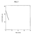
Fig. 2 is a graph showing output power reduction of a fuel cell using a cell having an anode in which no component that is effective in suppressing soot generation is added. - [
Fig. 3 ]
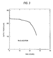
Fig. 3 is a graph showing output power reduction of a fuel cell using a cell having an anode in which Rh2O3 is added at 5 wt%. - [
Fig. 4 ]
Fig. 4 is a graph showing output power reduction of a fuel cell using a cell having an anode in which CaCO3 and Rh2O3 are added at 3 wt% and 5 wt%, respectively. - [
Fig. 5 ]
Figs. 5A to 5C are photographs, taken after power generation of 15 hours, of the anode surfaces of a sample using an outer anode layer in which neither Rh2O3 nor CaCO3 is added, a sample using an outer anode layer in which only Rh2O3 is added, and a sample using an outer anode layer in which both of Rh2O3 and CaCO3 are added. - [
Fig. 6 ]
Fig. 6 is a graph showing a relationship between the amount of CaCO3 added in the outer anode layer and the time taken until the output power of the fuel cell decreases to 50% of an initial value. - In a process of developing a technique for suppressing generation of soot that is attached to the anode of a direct-flame fuel cell, the present inventors have found that Rh2O3 which is added as an oxidation catalyst exhibits an effect of suppressing soot generation. Specifically, a cell is prepared in which, as shown in
Fig. 1 , ananode 2 having a two-layer structure (formed by aninner anode layer 2a made of SDC (60 wt%)-Ni0.9Co0.1O and anouter anode layer 2b which is made of SDC (30 wt%)-Ni0.9Co0.1O added with Rh2O3 (5 wt%)) is provided on one side of a solid electrolyte 1 made of samaria-doped ceria (SDC) and acathode 3 having a two-layer structure (formed by aninner cathode layer 3a made of SDC (50 wt%)-SSC and anouter cathode layer 3b made of a cathode material of SDC (30 wt%) -SSC added with a pore-forming material (55 vol%)) is provided on the other side of the solid electrolyte 1. To take out generated power to the outside,collectors outer anode layer 2b and theouter cathode layer 3b, respectively of the cell ofFig. 1 . For comparison, a comparative cell is prepared which had the same two-layer anode and cathode as the cell ofFig. 1 except that the outer anode layer does not contain Rh2O3. Each of the above cells is caused to generate power at a constant current (400 mA/cm2) while being exposed to a flame of a Bunsen burner to which a fuel-air mixture gas containing n-butane (6.5%), and a variation of the output power with time is observed. -
Figs. 2 and3 show results of the comparative cell and the cell using theouter anode layer 2b that is added with Rh2O3, respectively. In the comparative cell, soot is generated remarkably immediately after the start of power generation and the output power decreased steeply. In the cell using theouter anode layer 2b that is added with Rh2O3, output power reduction due to soot generation is observed after a lapse of about 20 hours. However, even in this case, it is difficult to suppress soot generation in the long-term power generation experiment. - The inventors have found that compounds of alkaline earth metals such as calcium, barium, and strontium and compounds of alkaline metals such as sodium, potassium, and cesium are effective in suppressing soot generation by studying the soot generation suppressing effect (like the one Rh2O3 exhibits) of various substances, and have completed the invention on the basis of this fact.
- Typical examples of such alkaline earth metal compounds are carbonates, oxides, hydroxides, nitrates, and sulfates of calcium, barium, and strontium. Typical examples of such alkaline metal compounds are carbonates, oxides, hydroxides, nitrates, and sulfates of sodium, potassium, and cesium. A mixture of alkaline metal compounds, a mixture of alkaline earth metal compounds, or a mixture of an alkaline metal compound and an alkaline earth metal compound may also be used.
- For example, it has been found that if CaCO3 is added at 3 wt% in the
outer anode layer 2b (containing Rh2O3 at 5 wt%) or the above-described cell, soot generation can be suppressed satisfactorily and output power reduction is delayed as shown inFig. 4 . -
Figs. 5A to 5C are photographs, taken after power generation of 15 hours, of the anode surfaces of sample 1 using an outer anode layer in which neither Rh2O3 nor CaCO3 is added,sample 2 using an outer anode layer in which only Rh2O3 is added, andsample 3 using an outer anode layer in which both of Rh2O3 and CaCO3 are added. It is seen that soot is attached to the entire surface of the anode in sample 1 (Fig. 5A ; neither Rh2O3 nor CaCO3 is added) and the degree of attachment of soot is lower in sample 2 (Fig. 5B ; only Rh2O3 is added) than in sample 1. Almost no soot is attached to the anode in sample 3 (Fig. 5C ; both of Rh2O3 and CaCO3 are added). The same test is performed on a sample in which only CaCO3 is added to produce a result that is the same as ofsample 3. - The anode of the fuel cell according to the invention is not limited to the above-described one having a two-layer structure, and may have a multilayer structure of three or more layers or a single-layer structure (described later). In each case, it is important that the alkaline metal compound or the alkaline earth metal compound (essentially a non-conductive substance) which is effective in suppressing soot generation due to exposure to a flame be added in the outermost layer of the cell that is directly exposed to a flame.
- In practice, it is preferable that CaCO3 be added at 1 to 10 wt% with respect to the amount of the anode materials irrespective of whether the anode contains Rh2O3. If the addition amount of CaCO3 is smaller than 1 wt%, the effect of suppressing soot generation is slight. If it is larger than 10 wt%, output power reduction starts earlier contrary to the intention. In the case of a multi-layered anode, the amount of the compound such as CaCO3 that is effective in suppressing soot generation is that in the outermost anode layer which is directly exposed to a flame.
- In the cell of the direct-flame fuel cell according to the invention, each of the solid electrolyte, the anode, and the cathode can be produced by a general method by using materials of a member of cells of ordinary solid electrolyte fuel cells except that the alkaline metal compound or the alkaline earth metal compound is added in the anode which is directly exposed to a flame at a sufficient amount to suppress soot generation.
- The material of the solid electrolyte may be one of the following materials (a), (b), and (c):
- (a) Ceria-based ceramics such as SDC (samaria-doped ceria) or GDC (gadolia-doped ceria).
- (b) Zirconia-based ceramics such as YSZ (yttria-stabilized zirconia), ScSZ (scandia-stabilized zirconia), or YSZ or ScSZ doped with Ce, Al, or the like.
- (c) LSGM (lanthangallate) or bismuth-oxide-based ceramics.
- The material of the anode may be one of the following materials (a), (b), (c), and (d):
- (a) A cermet of nickel, cobalt, and yttria-stabilized-zirconia-based ceramics, scandia-stabilized-zirconia-based ceramics, or ceria-based ceramics (SDC, GDC, or YDC).
- (b) A cermet of nickel and yttria-stabilized-zirconia-based ceramics, scandia-stabilized zirconia-based ceramics, or ceria-based ceramics (SDC, GDC, YDC, or the like).
- (c) A sintered body having a conductive oxide as the main component (50 to 99 wt%). For example, the conductive oxide may be a solid solution of nickel oxide and lithium.
- (d) A material obtained by adding a platinum-group metal or its oxide to one of the materials (a)-(d) at 1 to 10 wt%.
- In the invention, a preferable anode electrode material is one containing a cermet of nickel oxide and cobalt oxide.
- The material of the cathode may be a strontium (St) -added cobalate compound ot a rare earth element such as lanthanum or samarium (e.g., samarium strontium cobaltite or lanthanum strontium cobaltite), a strontium-added manganate compound of lanthanum (e.g., lanthanum strontium manganite), a strontium-added gallate compound of lanthanum, or a strontium-added ferrite compound (e.g., lanthanum strontium cobalt ferrite). If necessary, a carbon-based pore-forming material or the like may be added in the cathode.
- Each of the anode and the cathode may have either a single-layer structure or a multilayer structure. In the case of the multilayer structure, it is appropriate that the compound that contributes to suppression of soot generation, which is an important element of the invention, be added in the outermost portion (layer) of the anode that is directly exposed to a flame. In the case of the multilayer structure, the number of layers of the anode or cathode may be two or more.
- The direct-flame fuel cell according to the invention is useful as a single-cell fuel cell which generates power in an atmosphere that is a mixture of a fuel component and an oxidizing agent component, and is particularly useful as an open-to-air fuel cell which generates power in a state that the cell is exposed to a flame in an open-to-air atmosphere rather than in a state that the cell is placed in a closed space.
- Although Examples of the invention will be described below, the invention is not limited to them.
- A cell is produced according to the following procedure.
An SDC (samaria-doped ceria, Sm0.2Ce0.8O1.9) ceramic substrate to be used as a solid electrolyte is prepared. This SDC ceramic substrate which is a circular plate of 180 µm in thickness and 15 mm in diameter is produced in the following manner. A green sheet is shaped by a doctor blademethod. Fibrous cloths are applied to both surfaces of the green sheet and the green sheet is pressed at about 15 MPa (150 kg/cm2) by hydraulic pressing, whereby the surfaces of the green sheet is roughened. The thus-processed green sheet is punched into a circular plate and then fired at 1,300°C. - Ni0.9Co0.1Ox paste added with SDC at 60 wt% is printed on one surface (area: 1.8 cm2) of the ceramic substrate in an area of 1.3 cm2 as an inner anode layer, and Ni0.9Co0.1Ox paste added with CaCO3, Rh2O3 and SDC at 3 wt%, 5 wt% and 30 wt%, respectively, is printed thereon in an area of 1.3 cm2 as an outer anode layer. SSC (samarium strontium cobaltite, Sm0.5Sr0.5CoO3) paste added with SDC at 50 wt% is printed on the other surface in an area of 1.3 cm2 as an inner cathode layer, and SSC paste added with SDC and a carbon powder (pore-forming material) at 30 wt% and 55 vol%, respectively, is printed thereon as an outer cathode layer.
- Then, an assembly in which platinum meshes formed by welding platinum wires are buried in the printed pastes of the outer anode layer and the outer cathode layer is fired in the air at 1,200°C for one hour, whereby a cell of a solid oxide fuel cell (i.e., a cell whose anode and cathode had a two-layer structure as shown in
Fig. 1 ) is produced. - For comparison, a cell of a solid oxide fuel cell is produced according to the same procedure except that a paste that is not added with CaCO3 is used for forming an outer anode layer.
- The generation of soot on the anode surface is evaluated by exposing the cell to the flame of a Bensen burner to which a fuel-air mixture gas containing n-butane (6.5%) is supplied at a total flow rate of 400 sccm. Power is generated for a long time with such a load that a constant current (400 mA/cm2) flows and the generation of soot on the anode surface is checked in a state that the anode of the cell is exposed to the flame.
Figs. 5B and 5C , which are referred to above, are photographs of the anode surfaces of the cells taken after power generation of 15 hours. It is clearly seen that the amount of generated soot is smaller in the anode that is added with CaCO3 (Fig. 5C ) than in the anode that is not added with CaCO3 (Fig. 5B ). The durability of the cell whose anode is added with CaCO3 is improved accordingly. - Experiments are conducted in the same manner as in Example 1 while the amount of CaCO3 added to the paste for the outer anode layer is varied, and the time taken until the output power of the fuel cell decreased to 50% of an initial value is measured.
Fig. 6 shows results. It is seen from the results that the practical amount of CaCO3 added in the outer anode layer is about 1 to 10 wt%, preferably, 2 to 7 wt%. - As is understood from the above, the practical amount of a calcium compound that is added in the anode can be determined easily on the basis of the kinds of anode material and calcium compound used, flame conditions, etc. by conducting simple experiments. Likewise, the amount of a compound added other than calcium compounds that is effective in suppressing soot generation can be determined easily on the basis of the kinds of anode material and compound used, flame conditions, etc. by conducting simple experiments.
Claims (9)
- A direct-flame fuel cell comprising:a cell in which a solid electrolyte is sandwiched between an anode and a cathode, whereinthe anode (2) contains one or more kinds of alkaline metal compounds or alkaline earth metal compounds.
- The direct-flame fuel cell according to claim 1, wherein
the anode has a multilayer structure (2a, 2b), and
an outermost layer (2b) of the anode contains the one or more kinds of alkaline metal compounds or alkaline earth metal compounds. - The direct-flame fuel cell according to any of claims 1 to 2, wherein
the alkaline metal compounds is a carbonate, oxide, hydroxide, nitrate, or sulfate of sodium, potassium, or cesium. - The direct-flame fuel cell according to any of claims 1 to 3, wherein
the alkaline earth metal compounds is a carbonate, oxide, hydroxide, nitrate, or sulfate of calcium, barium, or strontium. - The direct-flame fuel cell according to any of claims 1 to 4, wherein
calcium carbonate is contained as the alkaline earth metal compound. - The direct-flame fuel cell according to claim 5, wherein the content of calcium carbonate is 1 to 10 wt%.
- The direct-flame fuel cell according to any of claims 1 to 6, wherein
a conductive electrode member of the anode contains a cermet of nickel oxide and cobalt oxide. - The direct-flame fuel cell according to any of claims 1 to 7, used as a single-cell fuel cell which generates power in an atmosphere that is a mixture of a fuel component and an oxidizing agent component.
- The direct-flame fuel cell according to any of claims 1 to 8, used as an open-to-air fuel cell which generates power in such a manner that the cell is exposed to a flame in an open-to-air atmosphere.
Applications Claiming Priority (1)
| Application Number | Priority Date | Filing Date | Title |
|---|---|---|---|
| JP2006325624A JP4999436B2 (en) | 2006-12-01 | 2006-12-01 | Direct flame fuel cell |
Publications (2)
| Publication Number | Publication Date |
|---|---|
| EP1928048A1 true EP1928048A1 (en) | 2008-06-04 |
| EP1928048B1 EP1928048B1 (en) | 2011-11-23 |
Family
ID=39086766
Family Applications (1)
| Application Number | Title | Priority Date | Filing Date |
|---|---|---|---|
| EP07023379A Ceased EP1928048B1 (en) | 2006-12-01 | 2007-12-03 | Direct-flame fuel cell |
Country Status (3)
| Country | Link |
|---|---|
| US (1) | US8252477B2 (en) |
| EP (1) | EP1928048B1 (en) |
| JP (1) | JP4999436B2 (en) |
Families Citing this family (11)
| Publication number | Priority date | Publication date | Assignee | Title |
|---|---|---|---|---|
| JP2010232134A (en) * | 2009-03-30 | 2010-10-14 | Mitsubishi Materials Corp | Durable fuel electrode and solid oxide fuel cell incorporating this fuel electrode |
| CN101916872B (en) * | 2010-08-27 | 2012-07-04 | 安徽工业大学 | Method for preparing cell slice of sulfur-oxygen solid oxide fuel cell |
| JP5603736B2 (en) * | 2010-10-27 | 2014-10-08 | 菊水化学工業株式会社 | Single cell for solid oxide fuel cell |
| WO2014126716A1 (en) * | 2013-02-13 | 2014-08-21 | Phillips 66 Company | Electrolyte formation for a solid oxide fuel cell device |
| JP6252973B2 (en) * | 2013-08-30 | 2017-12-27 | 住友電気工業株式会社 | Electrode catalyst material, fuel cell electrode, method for producing electrode catalyst material, and fuel cell |
| WO2015054024A1 (en) | 2013-10-08 | 2015-04-16 | Phillips 66 Company | Gas phase modification of solid oxide fuel cells |
| US10418657B2 (en) | 2013-10-08 | 2019-09-17 | Phillips 66 Company | Formation of solid oxide fuel cells by spraying |
| WO2015054065A1 (en) | 2013-10-08 | 2015-04-16 | Phillips 66 Company | Liquid phase modification of electrodes of solid oxide fuel cells |
| JP7395171B2 (en) * | 2018-03-08 | 2023-12-11 | 国立大学法人九州大学 | Anode for solid oxide fuel cells and solid oxide fuel cells |
| US20230138222A1 (en) * | 2020-06-24 | 2023-05-04 | Korea Advanced Institute Of Science And Technology | Solid oxide fuel cell comprising anode alkaline-based promoter loaded |
| KR102369060B1 (en) * | 2020-06-24 | 2022-03-02 | 한국과학기술원 | Solid oxide fuel cell comprising anode alkaline-based promoter loaded |
Citations (3)
| Publication number | Priority date | Publication date | Assignee | Title |
|---|---|---|---|---|
| US20040086761A1 (en) * | 2002-10-21 | 2004-05-06 | Shinko Electric Industries Co., Ltd. | Fuel cell structure |
| US20050048352A1 (en) * | 2003-08-29 | 2005-03-03 | Shinko Electric Industries Co., Ltd. | Fuel-cell device utilizing surface-migration on solid oxide |
| US20060257718A1 (en) * | 2005-05-12 | 2006-11-16 | Kazunori Sato | Electrode material and fuel cell |
Family Cites Families (10)
| Publication number | Priority date | Publication date | Assignee | Title |
|---|---|---|---|---|
| US4802958A (en) * | 1987-03-17 | 1989-02-07 | The Standard Oil Company | Process for the electrocatalytic oxidation of low molecular weight hydrocarbons to higher molecular weight hydrocarbons |
| JPH0973913A (en) * | 1995-09-04 | 1997-03-18 | Mitsubishi Heavy Ind Ltd | Fuel electrode of solid electrolytic fuel cell for internal reforming |
| US6846588B2 (en) * | 2002-01-16 | 2005-01-25 | Alberta Research Council Inc. | Hollow inorganic membranes produced by metal or composite electrodeposition |
| US20040018409A1 (en) * | 2002-02-28 | 2004-01-29 | Shiqiang Hui | Solid oxide fuel cell components and method of manufacture thereof |
| JP4319852B2 (en) * | 2003-04-08 | 2009-08-26 | 新光電気工業株式会社 | Fuel cell |
| JP2004319240A (en) * | 2003-04-16 | 2004-11-11 | Shinko Electric Ind Co Ltd | Combustion equipment |
| JP2006202737A (en) * | 2004-12-20 | 2006-08-03 | Kuraray Co Ltd | Ion conductive binder, membrane-electrode assembly and fuel cell |
| US7740968B2 (en) | 2004-12-20 | 2010-06-22 | Kuraray Co., Ltd. | Ion-conductive binder membrane-electrode assembly and fuel cell |
| JP2006179277A (en) * | 2004-12-22 | 2006-07-06 | Shinko Electric Ind Co Ltd | Fuel cell |
| US7297435B2 (en) * | 2005-03-10 | 2007-11-20 | Ovonic Fuel Cell Company, Llc | Solid oxide fuel cell |
-
2006
- 2006-12-01 JP JP2006325624A patent/JP4999436B2/en not_active Expired - Fee Related
-
2007
- 2007-11-30 US US11/948,379 patent/US8252477B2/en not_active Expired - Fee Related
- 2007-12-03 EP EP07023379A patent/EP1928048B1/en not_active Ceased
Patent Citations (3)
| Publication number | Priority date | Publication date | Assignee | Title |
|---|---|---|---|---|
| US20040086761A1 (en) * | 2002-10-21 | 2004-05-06 | Shinko Electric Industries Co., Ltd. | Fuel cell structure |
| US20050048352A1 (en) * | 2003-08-29 | 2005-03-03 | Shinko Electric Industries Co., Ltd. | Fuel-cell device utilizing surface-migration on solid oxide |
| US20060257718A1 (en) * | 2005-05-12 | 2006-11-16 | Kazunori Sato | Electrode material and fuel cell |
Non-Patent Citations (1)
| Title |
|---|
| HORIUCHI M ET AL: "Electrochemical Power Generation Directly from Combustion Flame of Gases, Liquids, and Solids", JOURNAL OF THE ELECTROCHEMICAL SOCIETY, vol. 151, no. 9, 2004, pages A1402 - A1405, XP002470640 * |
Also Published As
| Publication number | Publication date |
|---|---|
| JP4999436B2 (en) | 2012-08-15 |
| US8252477B2 (en) | 2012-08-28 |
| US20080131748A1 (en) | 2008-06-05 |
| JP2008140652A (en) | 2008-06-19 |
| EP1928048B1 (en) | 2011-11-23 |
Similar Documents
| Publication | Publication Date | Title |
|---|---|---|
| US8252477B2 (en) | Direct-flame fuel cell | |
| JP5208518B2 (en) | Method for producing a reversible solid oxide fuel cell | |
| JP5260052B2 (en) | Solid oxide fuel cell | |
| JP5213589B2 (en) | Metal-supported solid oxide fuel cell | |
| CN105940540B (en) | Electrochemical energy conversion device, battery, and positive electrode material for same | |
| US11283084B2 (en) | Fabrication processes for solid state electrochemical devices | |
| JP2012511243A (en) | Current collector for solid oxide fuel cell stack | |
| EP1791211B1 (en) | Solid electrolyte fuel cell comprising a fired anode and a multi-layered porous cathode | |
| JP2015088284A (en) | Solid oxide fuel cell | |
| EP1528615A2 (en) | Fuel cell | |
| JP6440178B2 (en) | Flat plate type solid oxide fuel cell and battery module including the same | |
| JP2006351405A (en) | SOFC fuel electrode and manufacturing method thereof | |
| JP2008300269A (en) | Solid oxide fuel cell and method for producing the same | |
| JP2014107063A (en) | Single chamber type solid oxide ful cell and air electrode thereof | |
| JP4426267B2 (en) | SOFC fuel electrode resistant to carbon deposition and method for producing the same | |
| KR20200036271A (en) | Solid oxide fuel cell and manufacturing method thereof | |
| JP6088949B2 (en) | Fuel cell single cell and manufacturing method thereof | |
| KR102814299B1 (en) | Positive electrode for solid oxide fuel cell and manufacturing method thereof | |
| KR101860079B1 (en) | Method of manufacturing anode material for solid oxide fuelcell | |
| US20260106178A1 (en) | Fuel electrode layer and electrochemical cell | |
| JP6172084B2 (en) | Anode for fuel cell and single cell for fuel cell | |
| JP2012074305A (en) | Power generation cell for solid oxide fuel cell | |
| JP2012074304A (en) | Power generation cell for solid oxide fuel cell | |
| JP2001196083A (en) | Solid oxide fuel cell | |
| CA2560769C (en) | Electrolyte electrode assembly and method of producing the same |
Legal Events
| Date | Code | Title | Description |
|---|---|---|---|
| PUAI | Public reference made under article 153(3) epc to a published international application that has entered the european phase |
Free format text: ORIGINAL CODE: 0009012 |
|
| AK | Designated contracting states |
Kind code of ref document: A1 Designated state(s): AT BE BG CH CY CZ DE DK EE ES FI FR GB GR HU IE IS IT LI LT LU LV MC MT NL PL PT RO SE SI SK TR |
|
| AX | Request for extension of the european patent |
Extension state: AL BA HR MK RS |
|
| 17P | Request for examination filed |
Effective date: 20080910 |
|
| AKX | Designation fees paid |
Designated state(s): DE |
|
| REG | Reference to a national code |
Ref country code: DE Ref legal event code: R079 Ref document number: 602007018855 Country of ref document: DE Free format text: PREVIOUS MAIN CLASS: H01M0008040000 Ipc: H01M0004860000 |
|
| GRAP | Despatch of communication of intention to grant a patent |
Free format text: ORIGINAL CODE: EPIDOSNIGR1 |
|
| RIC1 | Information provided on ipc code assigned before grant |
Ipc: H01M 8/12 20060101ALI20110517BHEP Ipc: H01M 4/86 20060101AFI20110517BHEP Ipc: H01M 4/90 20060101ALI20110517BHEP |
|
| RIN1 | Information on inventor provided before grant (corrected) |
Inventor name: SUGANUMA, SHIGEAKI Inventor name: TOKUTAKE, YASUE Inventor name: YOSHIIKE, JUN Inventor name: KATAGIRI, FUMIMASA |
|
| GRAS | Grant fee paid |
Free format text: ORIGINAL CODE: EPIDOSNIGR3 |
|
| GRAA | (expected) grant |
Free format text: ORIGINAL CODE: 0009210 |
|
| AK | Designated contracting states |
Kind code of ref document: B1 Designated state(s): DE |
|
| REG | Reference to a national code |
Ref country code: DE Ref legal event code: R096 Ref document number: 602007018855 Country of ref document: DE Effective date: 20120119 |
|
| PLBE | No opposition filed within time limit |
Free format text: ORIGINAL CODE: 0009261 |
|
| STAA | Information on the status of an ep patent application or granted ep patent |
Free format text: STATUS: NO OPPOSITION FILED WITHIN TIME LIMIT |
|
| 26N | No opposition filed |
Effective date: 20120824 |
|
| REG | Reference to a national code |
Ref country code: DE Ref legal event code: R097 Ref document number: 602007018855 Country of ref document: DE Effective date: 20120824 |
|
| PGFP | Annual fee paid to national office [announced via postgrant information from national office to epo] |
Ref country code: DE Payment date: 20201118 Year of fee payment: 14 |
|
| REG | Reference to a national code |
Ref country code: DE Ref legal event code: R119 Ref document number: 602007018855 Country of ref document: DE |
|
| PG25 | Lapsed in a contracting state [announced via postgrant information from national office to epo] |
Ref country code: DE Free format text: LAPSE BECAUSE OF NON-PAYMENT OF DUE FEES Effective date: 20220701 |