EP1927888A2 - Thin film transistor substrate and display device therefor - Google Patents
Thin film transistor substrate and display device therefor Download PDFInfo
- Publication number
- EP1927888A2 EP1927888A2 EP07022653A EP07022653A EP1927888A2 EP 1927888 A2 EP1927888 A2 EP 1927888A2 EP 07022653 A EP07022653 A EP 07022653A EP 07022653 A EP07022653 A EP 07022653A EP 1927888 A2 EP1927888 A2 EP 1927888A2
- Authority
- EP
- European Patent Office
- Prior art keywords
- drain electrode
- pixel
- drain
- thin film
- electrodes
- Prior art date
- Legal status (The legal status is an assumption and is not a legal conclusion. Google has not performed a legal analysis and makes no representation as to the accuracy of the status listed.)
- Granted
Links
- 239000010409 thin film Substances 0.000 title claims abstract description 112
- 239000000758 substrate Substances 0.000 title claims abstract description 66
- 239000010408 film Substances 0.000 claims description 52
- 239000003990 capacitor Substances 0.000 claims description 28
- 238000000034 method Methods 0.000 claims description 22
- 238000004519 manufacturing process Methods 0.000 claims description 5
- 230000003068 static effect Effects 0.000 abstract description 11
- 230000000694 effects Effects 0.000 abstract description 5
- 230000005611 electricity Effects 0.000 abstract description 5
- 239000004973 liquid crystal related substance Substances 0.000 description 24
- 229910052751 metal Inorganic materials 0.000 description 16
- 239000002184 metal Substances 0.000 description 16
- 239000000463 material Substances 0.000 description 10
- 238000005530 etching Methods 0.000 description 9
- 229910052782 aluminium Inorganic materials 0.000 description 5
- 229910052750 molybdenum Inorganic materials 0.000 description 4
- 229910052804 chromium Inorganic materials 0.000 description 3
- 230000004048 modification Effects 0.000 description 3
- 238000012986 modification Methods 0.000 description 3
- 238000000059 patterning Methods 0.000 description 3
- 229910052719 titanium Inorganic materials 0.000 description 3
- 229910000838 Al alloy Inorganic materials 0.000 description 2
- 229910052581 Si3N4 Inorganic materials 0.000 description 2
- VYPSYNLAJGMNEJ-UHFFFAOYSA-N Silicium dioxide Chemical compound O=[Si]=O VYPSYNLAJGMNEJ-UHFFFAOYSA-N 0.000 description 2
- 229910021417 amorphous silicon Inorganic materials 0.000 description 2
- 239000004020 conductor Substances 0.000 description 2
- 238000009413 insulation Methods 0.000 description 2
- 238000001459 lithography Methods 0.000 description 2
- 230000007257 malfunction Effects 0.000 description 2
- 239000011159 matrix material Substances 0.000 description 2
- 239000011368 organic material Substances 0.000 description 2
- HQVNEWCFYHHQES-UHFFFAOYSA-N silicon nitride Chemical compound N12[Si]34N5[Si]62N3[Si]51N64 HQVNEWCFYHHQES-UHFFFAOYSA-N 0.000 description 2
- 229910052814 silicon oxide Inorganic materials 0.000 description 2
- 125000006850 spacer group Chemical group 0.000 description 2
- 239000000126 substance Substances 0.000 description 2
- 229910052715 tantalum Inorganic materials 0.000 description 2
- 229910052779 Neodymium Inorganic materials 0.000 description 1
- 229910045601 alloy Inorganic materials 0.000 description 1
- 239000000956 alloy Substances 0.000 description 1
- 230000004075 alteration Effects 0.000 description 1
- 230000015556 catabolic process Effects 0.000 description 1
- 239000003086 colorant Substances 0.000 description 1
- 229910052802 copper Inorganic materials 0.000 description 1
- 239000011521 glass Substances 0.000 description 1
- 239000012535 impurity Substances 0.000 description 1
- AMGQUBHHOARCQH-UHFFFAOYSA-N indium;oxotin Chemical compound [In].[Sn]=O AMGQUBHHOARCQH-UHFFFAOYSA-N 0.000 description 1
- 238000002347 injection Methods 0.000 description 1
- 239000007924 injection Substances 0.000 description 1
- 229910010272 inorganic material Inorganic materials 0.000 description 1
- 239000011147 inorganic material Substances 0.000 description 1
- 239000011810 insulating material Substances 0.000 description 1
- 150000002739 metals Chemical class 0.000 description 1
- 230000003287 optical effect Effects 0.000 description 1
- 238000000206 photolithography Methods 0.000 description 1
- 230000000704 physical effect Effects 0.000 description 1
- 238000009832 plasma treatment Methods 0.000 description 1
- 229910021332 silicide Inorganic materials 0.000 description 1
- FVBUAEGBCNSCDD-UHFFFAOYSA-N silicide(4-) Chemical compound [Si-4] FVBUAEGBCNSCDD-UHFFFAOYSA-N 0.000 description 1
- 229910052709 silver Inorganic materials 0.000 description 1
- 238000002834 transmittance Methods 0.000 description 1
- YVTHLONGBIQYBO-UHFFFAOYSA-N zinc indium(3+) oxygen(2-) Chemical compound [O--].[Zn++].[In+3] YVTHLONGBIQYBO-UHFFFAOYSA-N 0.000 description 1
Images


Classifications
-
- G—PHYSICS
- G02—OPTICS
- G02F—OPTICAL DEVICES OR ARRANGEMENTS FOR THE CONTROL OF LIGHT BY MODIFICATION OF THE OPTICAL PROPERTIES OF THE MEDIA OF THE ELEMENTS INVOLVED THEREIN; NON-LINEAR OPTICS; FREQUENCY-CHANGING OF LIGHT; OPTICAL LOGIC ELEMENTS; OPTICAL ANALOGUE/DIGITAL CONVERTERS
- G02F1/00—Devices or arrangements for the control of the intensity, colour, phase, polarisation or direction of light arriving from an independent light source, e.g. switching, gating or modulating; Non-linear optics
- G02F1/01—Devices or arrangements for the control of the intensity, colour, phase, polarisation or direction of light arriving from an independent light source, e.g. switching, gating or modulating; Non-linear optics for the control of the intensity, phase, polarisation or colour
- G02F1/13—Devices or arrangements for the control of the intensity, colour, phase, polarisation or direction of light arriving from an independent light source, e.g. switching, gating or modulating; Non-linear optics for the control of the intensity, phase, polarisation or colour based on liquid crystals, e.g. single liquid crystal display cells
- G02F1/133—Constructional arrangements; Operation of liquid crystal cells; Circuit arrangements
- G02F1/136—Liquid crystal cells structurally associated with a semi-conducting layer or substrate, e.g. cells forming part of an integrated circuit
- G02F1/1362—Active matrix addressed cells
- G02F1/13624—Active matrix addressed cells having more than one switching element per pixel
-
- G—PHYSICS
- G02—OPTICS
- G02F—OPTICAL DEVICES OR ARRANGEMENTS FOR THE CONTROL OF LIGHT BY MODIFICATION OF THE OPTICAL PROPERTIES OF THE MEDIA OF THE ELEMENTS INVOLVED THEREIN; NON-LINEAR OPTICS; FREQUENCY-CHANGING OF LIGHT; OPTICAL LOGIC ELEMENTS; OPTICAL ANALOGUE/DIGITAL CONVERTERS
- G02F1/00—Devices or arrangements for the control of the intensity, colour, phase, polarisation or direction of light arriving from an independent light source, e.g. switching, gating or modulating; Non-linear optics
- G02F1/01—Devices or arrangements for the control of the intensity, colour, phase, polarisation or direction of light arriving from an independent light source, e.g. switching, gating or modulating; Non-linear optics for the control of the intensity, phase, polarisation or colour
- G02F1/13—Devices or arrangements for the control of the intensity, colour, phase, polarisation or direction of light arriving from an independent light source, e.g. switching, gating or modulating; Non-linear optics for the control of the intensity, phase, polarisation or colour based on liquid crystals, e.g. single liquid crystal display cells
- G02F1/133—Constructional arrangements; Operation of liquid crystal cells; Circuit arrangements
- G02F1/136—Liquid crystal cells structurally associated with a semi-conducting layer or substrate, e.g. cells forming part of an integrated circuit
- G02F1/1362—Active matrix addressed cells
- G02F1/136204—Arrangements to prevent high voltage or static electricity failures
-
- G—PHYSICS
- G02—OPTICS
- G02F—OPTICAL DEVICES OR ARRANGEMENTS FOR THE CONTROL OF LIGHT BY MODIFICATION OF THE OPTICAL PROPERTIES OF THE MEDIA OF THE ELEMENTS INVOLVED THEREIN; NON-LINEAR OPTICS; FREQUENCY-CHANGING OF LIGHT; OPTICAL LOGIC ELEMENTS; OPTICAL ANALOGUE/DIGITAL CONVERTERS
- G02F1/00—Devices or arrangements for the control of the intensity, colour, phase, polarisation or direction of light arriving from an independent light source, e.g. switching, gating or modulating; Non-linear optics
- G02F1/01—Devices or arrangements for the control of the intensity, colour, phase, polarisation or direction of light arriving from an independent light source, e.g. switching, gating or modulating; Non-linear optics for the control of the intensity, phase, polarisation or colour
- G02F1/13—Devices or arrangements for the control of the intensity, colour, phase, polarisation or direction of light arriving from an independent light source, e.g. switching, gating or modulating; Non-linear optics for the control of the intensity, phase, polarisation or colour based on liquid crystals, e.g. single liquid crystal display cells
- G02F1/133—Constructional arrangements; Operation of liquid crystal cells; Circuit arrangements
- G02F1/136—Liquid crystal cells structurally associated with a semi-conducting layer or substrate, e.g. cells forming part of an integrated circuit
- G02F1/1362—Active matrix addressed cells
- G02F1/136286—Wiring, e.g. gate line, drain line
Definitions
- the present invention relates to a thin film transistor substrate and a display device therefore and, more particularly, to preventing display aberrations.
- a liquid crystal display device is a kind of flat display device that displays images by using the optical anisotropic and polarizable properties of liquid crystal. That is, the liquid crystal display device controls the transmittance of light by controlling the orientation of the liquid crystal molecules.
- Liquid crystal display devices tend to produce ghost images during the display of moving pictures.
- dot inversion is obtained through alternate driving in which pixel voltages having different polarities are applied to sub-pixel electrodes in neighboring pixel regions. Malfunction of elements due to static electricity is prevented by increasing the pixel contact areas of the drain electrodes connected to the plurality of sub-pixel electrodes formed in a pixel region.
- An exemplary embodiment of the invention comprises a thin film transistor substrate that includes: a plurality of gate lines; a plurality of first and second data lines intersecting the gate lines; a plurality of first and second thin film transistors formed in unit pixel regions each defined by a gate line, a first data line, and a second data line having first and second drain electrodes, respectively; a plurality of first and second pixel electrodes formed in the unit pixel regions; a plurality of first drain electrode plates each of which is connected to the first pixel electrode and one of the first and second drain electrodes included in the unit pixel region; and a plurality of second drain electrode plates each of which is connected to the second pixel electrode and the other of the first and second drain electrodes included in the unit pixel region.
- the first and second drain electrode plates are formed between extension portions of the first and second drain electrodes.
- the center line connecting the centers of the first and second drain electrode plates in each unit pixel region intersects the gate lines.
- the thin film transistor substrate may further include a plurality of storage electrode plates each of which partially overlaps the first and second electrode plates in each unit pixel region. In each unit pixel region, the storage electrode plate is formed between the extension portions of the first and second drain electrodes.
- the first drain electrode is connected to the first drain electrode plate and the second drain electrode is connected to the second drain electrode plate.
- the first drain electrode is connected to the second drain electrode plate, and the second drain electrode is connected to the first drain electrode plate.
- the first thin film transistor is connected to the gate line and the first data line and the second thin film transistor be connected to the gate line and the second data line.
- An exemplary embodiment of the invention comprises a display device that includes: a plurality unit pixels each of which includes a first pixel capacitor having a first pixel electrode and a common electrode and a second pixel capacitor having a second pixel electrode and the common electrode; a plurality of first and second thin film transistors formed in the unit pixels, the first thin film transistor having a first drain electrode and the second thin film transistor having a second drain electrode; a plurality of first drain electrode plates each of which is connected to the first pixel electrode and one of the first and second drain electrodes in the unit pixel; and a plurality of second drain electrode plates each of which is connected to the second pixel electrode and the other of the first and second drain electrodes in the unit pixel.
- the first and second drain electrode plates are formed between extension portions of the first drain electrode and the second drain electrode.
- the first and second thin film transistors in each of the unit pixels are connected to one of the gate lines, the first thin film transistor is connected to the first data line, and the second thin film transistor is connected to the second data line. Also, in each of the unit pixels, a center line connecting the centers of the first and second drain electrodes intersects the gate lines.
- Each of the plurality of storage electrode plates partially overlaps the first and second drain electrodes in the corresponding unit pixel so as to form first and second storage capacitors.
- the first drain electrode is connected to the first drain electrode plate and the second drain electrode is connected to the second drain electrode plate.
- the first drain electrode is connected to the second drain electrode plate and the second drain electrode is connected to the first drain electrode plate.
- An exemplary display device includes: a plurality of gate lines; a plurality of first and second data lines; and a plurality of unit pixels each of which is formed along a gate line, a first data line, and a second data line, and includes a first pixel capacitor having a first pixel electrode and a common electrode, a second pixel capacitor having a second pixel electrode and the common electrode, a first storage capacitor having the first pixel electrode and a storage electrode plate, and a second storage capacitor having the second pixel electrode and the storage electrode plate.
- an extension line of the storage electrode plate extending in a major axis direction intersects the gate lines.
- the first storage capacitor is formed between the first pixel electrode and the storage electrode plate and further includes a first drain electrode plate connected to the first pixel electrode
- the second storage capacitor is formed between the second pixel electrode and the storage electrode plate and further includes a second drain electrode plate connected to the second pixel electrode.
- the display device may further include a plurality of first thin film transistors each having a first drain electrode and a plurality of second thin film transistors each having a second drain electrode.
- a portion of the first drain electrode extends to be connected to one of the first and second drain electrode plates
- a portion of the second drain electrode extends to be connected to the other of the first and second drain electrode plates
- the first and second drain electrodes are formed between the extension portions of the first and second drain electrodes.
- the first drain electrode is connected to the first drain electrode plate and the second drain electrode is connected to the second drain electrode plate.
- the first drain electrode is connected to the second drain electrode plate and the second drain electrode is connected to the first drain electrode plate.
- An exemplary method of manufacturing a display device comprises: forming, on a transparent substrate, a plurality of gate lines, a plurality of first and second gate electrodes, and a plurality of storage electrode plates whose extension lines in the major axis directions intersect the gate lines; forming a gate insulting film on the entire structure; forming an active layer on the first and second gate electrodes; forming a plurality of first and second data lines intersecting the gate lines, forming a plurality of first source electrodes and a plurality of first drain electrodes on the first gate electrodes, forming a plurality of second source electrodes and a plurality of second drain electrodes on the second gate electrodes, and forming a plurality of first and second drain electrode plates on the storage electrode plates such that the first drain electrode plate is connected to one of the first and second drain electrodes, the second drain electrode plate is connected to the other of the first and second drain electrodes, wherein a center line connecting the centers of the first and second drain electrode plates intersects the gate lines; forming, on the entire
- An exemplary thin film transistor substrate includes: a plurality of gate lines; a plurality of first and second data lines intersecting the gate lines; a plurality of first and second thin film transistors formed in unit pixel regions each defined by a gate line, a first data line, and a second data line, the first and second transistors having first and second drain electrodes, respectively; a plurality of first and second pixel electrodes formed in the unit pixel regions; a plurality of first drain electrode plates each of which is connected to the first pixel electrode and one of the first drain electrode and the second drain electrode in the unit pixel region; and a plurality of second drain electrode plates each of which is connected to the second pixel electrode and the other of the first drain electrode and the second drain electrode included in the unit pixel region.
- the first and second drain electrode plates are formed between extension portions of the first and second drain electrodes and a center line connecting the centers of the first and second drain electrodes intersects the gate lines.
- the first and second drain electrodes are disposed in a vertical direction.
- the first drain electrode is connected to the first drain electrode plate and the second drain electrode is connected to the second drain electrode plate.
- the first drain electrode is connected to the second drain electrode plate and the second drain electrode is connected to the first drain electrode plate.
- the thin film transistor substrate may further include a plurality of storage electrode plates each of which extends in a vertical direction to partially overlap the first and second drain electrode plates in each unit pixel region.
- Fig. 1 is a schematic plan view of a display device according to an exemplary embodiment of the invention.
- Figs. 2 and 3 are schematic cross-sectional views taken along the line A-A of Fig. 1 ;
- Figs. 4 and 5 are schematic cross-sectional views taken along the line B-B of Fig. 1 ;
- Fig. 6 is a schematic plan view of a thin film transistor substrate for alternate driving according to an exemplary embodiment of the invention.
- Fig. 7 is a schematic view for explaining the alternate driving of the display apparatus according to the exemplary embodiment.
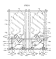
- Figs. 8 and 9 are schematic plan views of a thin film transistor substrate according to a modification of the invention.
- Figs. 10 to 13 are views for explaining a process of manufacturing a thin film transistor substrate according to an exemplary embodiment of the invention.
- Fig. 1 is a schematic plan view of a display device according to an exemplary embodiment of the invention
- Figs. 2 and 3 are schematic cross-sectional views taken along the line A-A of Fig. 1
- Figs. 4 and 5 are schematic cross-sectional views taken along the line B-B of Fig. 1
- Fig. 6 is a schematic plan view of a thin film transistor substrate for alternate driving according to an exemplary embodiment of the invention
- Fig. 7 is a schematic view for explaining the alternate driving of the display apparatus according to the exemplary embodiment.
- Figs. 8 and 9 are schematic plan views of a thin film transistor substrate according to a modification of the invention.
- a display device includes a thin film transistor substrate 1000, which is a lower substrate, a common electrode substrate 2000, which is an upper substrate disposed to face substrate 1000, and a liquid crystal layer (not shown) which is disposed between the two substrates and whose liquid crystal molecules are oriented in a desired direction with respect to the two substrates.
- a liquid crystal layer (not shown) which is disposed between the two substrates and whose liquid crystal molecules are oriented in a desired direction with respect to the two substrates.
- an alignment film (not shown) is provided to align the liquid crystal molecules of the liquid crystal layer. It is preferable that the liquid crystal molecules of the liquid crystal layer be vertically aligned with respect to the substrates.
- the invention is not limited thereto.
- the thin film transistor substrate 1000 includes a transmissive insulating substrate 100, and a plurality of gate lines 110, a plurality of first and second data lines 130a and 130b, a plurality of first and second pixel electrodes 170a and 170b, a plurality of first thin film transistors 120a, a plurality of second thin film transistors 120b, and a plurality of storage lines 140, which are provided on the transmissive insulating substrate 100.
- the gate lines 110 transmit gate signals and are arranged to extend in a first direction at predetermined intervals along a second direction.
- the first and second data lines 130a and 1 30b are formed to intersect the gate lines 110.
- the first and second pixel electrodes 170a and 1 70b are formed in pixel regions defined by the gate lines 110 and the first and second data lines 130a and 130b.
- the first thin film transistors 120a are connected to the first data lines 130a and the gate lines 110, and the second thin film transistors 120b are connected to the second data lines 1 30b and the gate lines 110.
- the storage lines 140 extend in parallel to the gate lines 110 to pass through the first and second pixel electrodes 170a and 1 70b.
- each of the first thin film transistors 120a and the second thin film transistors 1 20b are connected to the first pixel electrode 1 70a or the second pixel electrode 170b. More specifically, in each pixel region, when the first thin film transistor 1 20a is connected to the first pixel electrode 170a, the second thin film transistor 120b is connected to the second pixel electrode 1 70b, and when the first thin film transistor 1 20a is connected to the second pixel electrode 1 70b, the second thin film transistor 120b is connected to the first pixel electrode 170a.
- Each of the gate lines 110 extends substantially in a horizontal direction, and some portions of each of the gate lines 110 protrude upward and/or downward so as to form gate electrodes 121 a and 121 b of the above-mentioned first and second transistors 1 20a and 120b.
- a gate contact pad (not shown) for connection with an external circuit is formed.
- the gate lines 110 may be formed in a single-layered structure or a multi-layered structure of two or more layers. When the gate line 110 is formed in a multi-layered structure including two or more layers, it is preferable that one layer be formed of a low-resistance material and the other layers be formed of a material having good contact properties with other materials.
- the multi-layered structure examples include a two-layered structure of a Cr layer and an Al (or Al alloy) layer and a two-layered structure of an Al (or Al alloy) layer and a Mo layer.
- the gate lines 110 may be formed of any of various metals or conductive materials.
- the first and second data lines 130a and 130b extend substantially in a vertical direction and form pairs. Between a pair of first and second data lines 1 30a and 1 30b, a part of the plurality of first and second pixel electrodes 1 70a and 1 70b are disposed. Some portions of each of the first data lines 130a protrude such that each protruding portion forms a source electrode 125a of a first thin film transistor 1 20a. Some portions of each of the second data lines 1 30b protrude such that each protruding portion forms a source electrode 125b of a second thin film transistor 120b. At an end of each of the first and second data lines 1 30a and 1 30b, a data contact pad (not shown) is formed.
- the first and second data lines 130a and 130b may be formed in a single-layered structure or a multi-layered structure of two or more layers having different physical properties.
- first and second data lines 1 30a and 1 30b are formed in a multi-layered structure of two or more layers, it is preferable to form one layer of a low-resistance material in order to reduce delay of a data signal or a drop in voltage and to form the other layers of materials having good contact properties with other materials.
- first and second data lines 1 30a and 1 30b are shown in the shape of a straight line in the drawings, the first and second data lines 130a and 1 30b may have some bent portions.
- the first and second pixel electrodes 1 70a and 1 70b may be formed along the bent portions of the first and second data lines 1 30a and 130b.
- Each of the storage lines 140 includes a plurality of storage electrode plates 141 that partially overlap the first and second pixel electrodes 170a and 170b and a storage electrode line 142 that is connected with the storage electrode plate 141 and extends in the same direction as the direction in which the gate lines 110 extend.
- the storage lines 140 are made of the same material as the gate lines 110 and are patterned together with the data lines 110 at the same time.
- an end of each storage line 140 is connected to a common voltage source Vcom.
- the storage electrode plate 141 is preferably provided between the two extending lines to have substantially a rectangular shape.
- the storage electrode plate 141 is formed in a substantially rectangular shape whose longer side extends in a direction intersecting the extended direction of the storage electrode line 142 (that is, the direction in which the gate line 110 extends).
- the extended direction of the longer side of the storage electrode plate 141 be orthogonal to the extended direction of the storage electrode line 142.
- the storage electrode plate 141 be disposed in the central portion of the pixel region.
- this exemplary embodiment is not limited thereto.
- an extension line of the storage electrode plate 141 in the extended direction of the longer side of the storage electrode plate 141 and the extended direction of the storage electrode line 142 intersect at a predetermined angle as shown in Fig. 8 . It is preferable that the predetermined angle be within the range of 0° to 90°.
- the storage electrode plate 141 may be disposed in a region adjacent to the gate line 110 as shown in Fig. 8 . Further, the storage electrode plate 141 may be formed in the shape of a circle as shown in Fig. 9 .
- the storage electrode plate 141 can also be formed in, for example, the shape of a polygon, the shape of a semicircle, the shape of an ellipse, or the shape of a half ellipse, other than the shape of a circle.
- the upper portion of the storage electrode plate 141 partially overlaps the second pixel electrode 1 70b so as to form a second storage capacitor.
- a second drain electrode plate 150b is provided to be connected to the second pixel electrode 1 70b through a second pixel contact hole 162. It is possible to increase the electrostatic capacity of the second storage capacitor through the second drain electrode plate 1 50b.
- the lower portion of the storage electrode plate 141 partially overlaps the first pixel electrode 170a so as to form a first storage capacitor.
- a first drain electrode plate 1 50a is provided to be connected to the first pixel electrode 1 70a through a first pixel contact hole 161. It is possible to increase the electrostatic capacity of the first storage capacitor through the first drain electrode plate 150a.
- the electrostatic capacity of the first storage capacitor and the electrostatic capacity of the second storage capacitor can be controlled by adjusting the overlapping area of the first drain electrode plate 1 50a and the storage electrode plate 141 and the overlapping area of the second drain electrode plate 150b and the storage electrode plate 141.
- a portion of the first drain electrode plate 1 50a may extend to an area (a slit pattern region) separated from the first pixel electrode 1 70a so as to overlap the storage electrode plate 141, and a portion of the second drain electrode plate 1 50b may extend to a space separated from the second pixel electrode 1 70b so as to overlap the storage electrode plate 141.
- the invention is not limited thereto.
- the upper portion of the storage electrode plate 141 may overlap the first pixel electrode 1 70a and the lower portion of the storage electrode plate 141 may overlap the second pixel electrode 170b.
- the first thin film transistor 120a includes a first gate electrode 121 a, a first source electrode 125a, and a first drain electrode 126a
- the second thin film transistor 120b includes a second gate electrode 121b, a second source electrode 125b, and a second drain electrode 126b.
- a portion of the first drain electrode 126a extends to be connected to the first drain electrode 150a
- a portion of the second drain electrode 126b extends to be connected to the second drain electrode 150b.
- the first and second source electrodes 125a and 125b, the first and second drain electrodes 126a and 126b, and the first and second drain electrode plates 1 50a and 1 50b are formed of the same material as the first and second data lines 1 30a and 130b and are patterned together with the first and second data lines 1 30a and 1 30b at the same time.
- the first source electrode 125a is made by protruding a portion of the data line 130a such that the end of the protruding portion is positioned on the first gate electrode 121 a.
- the second source electrode 125b is made by protruding a portion of the data line 1 30a such that the end of the protruding portion is positioned on the second gate electrode 121b.
- the first drain electrode 1 26a extends from the upper side of the first gate electrode 121 a to be connected to the first drain electrode plate 1 50a.
- the first drain electrode 126a includes a first extending portion 126a-1 that is adjacent to the first data line 1 30a and extends in the same direction as the first data line 130a, and a second extending portion 126a-2 extending from the first extending portion 126a-1 toward the first drain electrode plate 150a.
- the second drain electrode 1 26b extends from the upper side of the second gate electrode 121 b to be connected to the second drain electrode plate 150b. As shown in Fig.
- the second drain electrode 126b includes a first extending portion 126b-1 that is adjacent to the second data line 1 30b and extends in the same direction as the second data line 130b, and a second extending portion 126b-2 extending from the first extending portion 126b-1 toward the second drain electrode plate 150b.
- the first drain electrode plate 1 50a is formed in a plate shape underneath the first pixel electrode 170a
- the second drain electrode plate 150b is formed in a plate shape underneath the second pixel electrode 1 70b.
- the first and second drain electrode plates 150a and 1 50b are formed between the first extending portion 126a-1 of the first drain electrode 1 26a and a virtual extension line thereof, and the second extending portion 126b-1 of the second drain electrode 126b and a virtual extension line thereof.
- the second drain electrode plate 1 50b be positioned upside the first drain electrode plate 150a, as shown in Fig. 1 . That is, it is preferable that a center line linking the centers of the first and second drain electrode plates 1 50a and 1 50b intersect the gate line 110. It is more preferable that the center line and the gate line 110 be perpendicular to each other, as shown in Figs. 1 and 6 . The center line may intersect the gate line 110 at a predetermined angle, as shown in Figs. 8 and 9 . This exemplary embodiment is not limited thereto.
- the first drain electrode plate 150a may be positioned upside the second drain electrode plate 1 50b.
- the first drain electrode 1 26a may be connected to the second drain electrode plate 150b, and the second drain electrode 126b may be connected to the first drain electrode plate 1 50a.
- the first drain electrode 126a may be connected to the first drain electrode plate 150a and the second drain electrode 126b may be connected to the second drain electrode plate 1 50b.
- the first and second drain electrode plates 1 50a and 1 50b are made in a substantially rectangular shape. However, this exemplary embodiment is not limited thereto.
- the first and second drain electrode plates 1 50a and 1 50b may be formed in the shape of a circle, as shown in Fig. 9 . Also, the first and second drain electrode plates 1 50a and 150b can also be formed in the shape of a polygon, the shape of a semicircle, the shape of a half ellipse, or the shape of an ellipse, other than the shape of a circle.
- the drain electrodes 126a and 126b of the thin film transistors 120a and 120b are positioned in the form of floating metal wiring line that is not connected to the external wiring line during the process of manufacturing the display device. Therefore, when the drain electrodes are connected to an external wiring line or when the manufacturing process (for example, a plasma treatment process) is performed, charges are stored in the floating metal. When the amount of stored charges exceeds the amount of charges (that is, a threshold) that the floating metal can store, static discharge may occur that breaks down the insulation between the floating metal and a metal adjacent to the floating metal. The break-down of insulation damages the elements.
- the amount of charges that the floating metal can store is small and thus static discharge may occur.
- the size of the floating metal is large, the amount of charges that the floating metal can store is large, and thus it is possible to prevent static discharge. Therefore, in this exemplary embodiment, by increasing the contact areas of the drain electrodes 1 26a and 1 26b of the thin film transistors 1 20a and 120b with the drain electrode plates 1 50a and 1 50b, it is possible to prevent static discharge due to the drain electrodes 1 26a and 1 26b.
- two pixel electrodes 170a and 170b are provided and are charged with different pixel signals.
- the first and second thin film transistors 120a and 120b supply, to the first and second pixel electrodes 170a and 170b, first and second pixel signals (grayscale voltages) which are supplied to the first and second data lines 1 30a and 1 30b in response to a signal supplied to the gate line 110, respectively. That is, as described above, in one pixel region, the first pixel electrode 170a is charged with the first pixel signal of the first data line 130a through the first thin film transistor 120a, and the second pixel electrode 1 70b is charged with the second pixel signal of the second data line 130b through the second thin film transistor 1 20b.
- the first pixel electrode 170a is charged with the second pixel signal of the second data line 130b through the second thin film transistor 120b, and the second pixel electrode 170b is charged with the first pixel signal of the first data line 130a through the first thin film transistor 120a. In this way, the display device can be alternately driven.
- An insulating protection film 160 is formed on the first and second thin film transistors 120a and 1 20b and the first and second data lines 130a and 130b.
- the protection film 160 may be formed of an inorganic material, such as silicon nitride or silicon oxide, or an organic material having a low dielectric constant.
- the first and second contact holes 161 and 162 are formed in the insulating protection film 160 to expose portions of the first and second drain electrode plates 1 50a and 150b.
- the first and second pixel electrodes 170a and 1 70b are formed on the protection film 160.
- the first pixel electrode 1 70a has the shape of a bent band and substantially has mirror symmetry with respect to a line bisecting the pixel region into upper and lower equal parts. As shown in Fig. 1 , the first pixel electrode 1 70a includes a first band extending from an upper left portion of the pixel region to a center right region of the pixel region, a second band extending from a lower left portion of the pixel region to the center right region of the pixel region, and a third band connecting the first and the second bands in the center right region of the pixel region.
- the first pixel electrode 170a is made in a substantial V shape. It is preferable that the angle of inclination of each of the first and second bands relative to the gate line 110 be about 45°. However, the angle of inclination is not limited thereto, but it may be variable.
- the second pixel electrode 1 70b is made in a substantial V shape surrounding the first pixel electrode 1 70a and has mirror symmetry.
- the second pixel electrode 1 70b includes a first plate provided between the first and second bands of the first pixel electrode 1 70a, a second plate provided in an upper region of the first band to be connected to the first plate, and a third plate provided in a lower region of the second band to be connected to the first and second plates.
- the first drain electrode plate 1 50a is provided in the second band region of the first pixel electrode 1 70a and the second drain electrode plate 1 50b is provided in the first plate region of the second pixel electrode 1 70b.
- the first drain electrode plate 1 50a may be provided in the first band region of the first pixel electrode 1 70a, as shown in Fig. 6 .
- the second drain electrode plate 1 50b may be provided in the third plate region of the second pixel electrode 1 70b as shown in Fig. 8 .
- the first and second pixel electrodes 170a and 170b are separated from each other, and preferably have a plurality of slit patterns 171 as a domain restricting unit for controlling the orientation of liquid crystal.
- the first and second pixel electrodes 170a and 170b may have various domain restricting units.
- the common electrode substrate 2000 includes: an insulating substrate 200 made of a transparent insulating material, such as glass; a plurality of red, green, and blue color filters 220 and a black matrix 210 formed on a lower surface of the insulating substrate 200 to prevent light leakage and light interference between adjacent pixel regions; and an overcoat film 230 made of an organic material on the color filters 220.
- a common electrode 240 is formed of a transparent conductive material, such as ITO or IZO.
- the common electrode 240 is provided with a plurality of protrusion patterns 241 as shown in Figs. 2 and 4 or a plurality of slit patterns 242 as shown in Figs. 3 and 5 .
- the plurality of protrusion patterns 241 or slit patterns 242 are formed at positions bisecting the first and second pixel electrodes 1 70a and 1 70b.
- Slit patterns 171 of the first and second pixel electrodes 1 70a and 170b and the protrusion patterns 241 or the slit patterns 242 of the common electrode 240 serve as domain restricting units for dividing and orienting the liquid crystal. These domain restricting units may be provided in the first and second pixel electrodes 170a and 170b and/or the common electrode 240.
- First and second sub-pixel capacitors are provided between the first and second pixel electrodes 1 70a and 1 70b and the common electrode 240. In this way, it is possible to form a unit pixel having two sub-pixel capacitors in one pixel region.
- the thin film transistor substrate 1000 and the common electrode substrate 2000 are bonded to each other with a liquid crystal layer interposed therebetween to form a basic panel of the display device according to the exemplary embodiment of the invention, in which the first and second sub-pixels are provided in one unit pixel.
- the display device has liquid crystal having negative type dielectric constant anisotropy between the upper and lower substrates and vertically orients the liquid crystal.
- the invention is not limited thereto. Elements, such as polarizing plates, a back light, and a compensating plate, may be disposed on both sides of the basic panel of the display device.
- first and second grayscale voltages are applied to the first and second pixel electrodes 170a and 170b in the unit pixel
- potential difference occurs between the common electrode 240 to which a common voltage Vcom is applied and the first and second pixel electrodes 1 70a and 170b.
- the potential difference causes the liquid crystal positioned between the thin film transistor substrate 1000 and the common electrode substrate 2000 to be rotated by the dielectric constant anisotropy such that the amount of light incident from a light source (not shown) through the pixel electrodes 1 70a and 1 70b is controlled and the light is emitted toward the common electrode substrate 2000.
- the light emitted toward the common electrode substrate 2000 passes through the color filters 220 provided on the common electrode substrate 2000 such that desired colors are displayed.
- the alternate driving (dot inversion driving) of the display device will be described below focusing on the application of grayscale signals to the first and second pixel electrodes 170a and 1 70b of the thin film transistor substrate 1000.
- a gate turn-on voltage supplied from the outside is sequentially supplied to the plurality of gate lines 110 and a plurality of grayscale voltages are supplied to the first and second data lines 1 30a and 130b.
- the gate turn-on voltage is applied to the gate line 110, a plurality of first and second thin film transistors 120a and 1 20b connected to the corresponding gate line 110 are turned on. Therefore, the first grayscale signal of the first data line 130a connected to the first thin film transistor 120a is applied to the first pixel electrode 1 70a or the second pixel electrode 170b connected to the first thin film transistor 120a.
- the second grayscale signal of the second data line 1 30b connected to the second thin film transistor 120b is applied to the first pixel electrode 170a or the second pixel electrode 170b connected to the second thin film transistor 120b.
- FIG. 6 Two adjacent unit pixel region patterns are shown in Fig. 6 .
- a pixel region pattern disposed on the left side of Fig. 6 is referred to as a first pixel region pattern, and the other pixel region pattern disposed on the right side of Fig. 6 is referred to as a second pixel region pattern.
- the first and second thin film transistors 1 20a and 120b are turned on. Therefore, the first and second pixel electrodes 1 70a and 170b of the first pixel region pattern are electrically connected to the first and second data lines 130a and 130b, respectively.
- the first and second pixel electrodes 170a and 170b of the second pixel region pattern are electrically connected to the second and first data lines 1 30b and 1 30a, respectively.
- the electrical connection relationship between the first and second electrodes 170a and 170b of the first pixel region pattern and the first and second data lines 1 30a and 1 30b is opposite to the electrical connection relationship between the first and second electrodes 1 70a and 1 70b of the second pixel region pattern and the first and second data lines 1 30a and 130b.
- the display device performs line inversion driving, that is, driving for inverting the polarities of signals for neighboring data lines.
- line inversion driving that is, driving for inverting the polarities of signals for neighboring data lines.
- the frame frequency of the display device is higher than 60 Hz (for example, 120 Hz)
- the loading of the data lines increases and thus dot inversion driving is not practicable.
- a positive first grayscale signal of the second D2-a of the first data lines is applied to the second pixel electrode 170b in the second pixel region, and a negative second grayscale signal of the second D2-b of the second data lines is applied to the first pixel electrode 1 70a in the second pixel region.
- a positive first grayscale signal of the third D3-a of the first data lines is applied to the first pixel electrode 1 70a in a third pixel region, and a negative second grayscale signal of the third D3-b of the second data lines is applied to the second pixel electrode 1 70b in the third pixel region.
- the first pixel electrode 170a in the first pixel region is charged with a positive voltage and the first pixel electrode 1 70a in the second pixel region adjacent to the first pixel region is charged with a negative voltage.
- the second pixel electrode 170b in the first pixel region is charged with a negative voltage and the second pixel electrode 170b in the second pixel region adjacent to the first pixel region is charged with a positive voltage.
- the pixel electrodes 1 70a in neighboring pixel regions are charged with grayscale voltages having different voltage levels, and similarly, the pixel electrodes 1 70b in neighboring pixel regions are charged with grayscale voltages having different voltage levels. Therefore, it is possible to perform dot inversion driving, which makes it possible to prevent a vertical line stain from being generated.
- the first and second thin film transistors 120a and 120b are turned on or off at the same time, it is possible to simultaneously supply the first and second grayscale signals to the first and second pixel electrodes 1 70a and 1 70b during a time period of 1 H. Therefore, even though the frame frequency increases, it is possible to ensure enough time to charge the first and second pixel electrodes 170a and 170b with the first and second grayscale voltages.
- Figs. 10 to 13 are views illustrating processes of forming a thin film transistor substrate according to an exemplary embodiment of the invention.
- a first conductive film is formed on a transparent insulating substrate 100 and is patterned to form the gate lines 110, the first and second gate electrodes 121 a and 121 b, and the storage lines 140 including the storage electrode plates 141 and the storage electrode lines 142.
- the first conductive film be formed of at least one of Cr, MoW, Cr/Al, Cu, Al(Nd), Mo/Al, Mo/Al(Nd), Cr/Al(Nd), and Mo/Al/Mo.
- the invention is not limited thereto.
- the first conductive film may be formed of at least one metal of Al, Nd, Ag, Cr, Ti, Ta, and Mo, or alloys thereof to have a single-layered or multi-layered structure. That is, the first conductive film may be formed in a double-layered or triple-layered structure including a metal layer formed of, for example, Cr, Ti, Ta, and Mo having excellent physical and chemical properties and an Al-based metal layer or an Ag-based metal layer having low specific resistance.
- a photosensitive film is coated. Then, a lithography method using a first photosensitive film mask is performed to from a first photosensitive film mask pattern. An etching process using the first photosensitive film mask pattern as a mask for etching is performed to form the gate lines 110, the plurality of first and second gate electrodes 121 a and 121 b, and the storage lines 140 horizontally extending in correspondence with the gate lines 110, as shown in Fig. 10 . Then, a predetermined strip process is performed to remove the first photosensitive film mask pattern.
- Each of the gate lines 110 is formed so as to be laid across a plurality of pixel regions.
- the first and second gate electrodes 121 a and 121 b and the storage electrode plate 141 of the storage line 140 are formed in each pixel region.
- the storage electrode plates 141 provided in the individual pixel regions are connected through the storage electrode lines 142.
- the gate lines 110 and the storage electrode lines 142 extend in a horizontal direction.
- the storage electrode plates 141 are formed in the shape of a plate extending to intersect the extension direction of the storage electrode lines 142.
- a gate insulating film 122, a thin film for an active layer, and a thin film for an ohmic contact layer are sequentially formed on the substrate 100 having the gate lines 110 formed thereon, and the thin film for an active layer and the thin film for an ohmic contact layer are patterned to form an active area of the first and second thin film transistors including active layers 123a and 123b and ohmic contact layers 124a and 124b.
- the gate insulating film 122 be formed of an inorganic insulting material, such as silicon oxide or silicon nitride.
- An amorphous silicon layer is used as the thin film for an active layer and an amorphous silicon layer heavily doped with silicide or N-type impurities is used as the thin film for an ohmic contact layer.
- a photosensitive film is coated on the thin film for an ohmic contact layer and a photolithography method using a second mask is performed to form a second photosensitive film mask pattern.
- An etching process in which the second photosensitive film mask pattern is used as a mask for etching and the gate insulating film 122 is set to an etching stop film is performed to form an active area including the ohmic contact layers 124a and 124b and the active layers 123a and 123b on the first and second electrodes 121 a and 121 b.
- a patterning process is performed to form the plurality of first and second data lines 1 30a and 130b, the plurality of first and second source electrodes 125a and 125b, the plurality of first and second drain electrodes 126a and 126b, and a plurality of first and second drain electrode plates 1 50a and 1 50b that overlap the storage electrode plates 141.
- the first and second drain electrodes 126a and 126b are formed such that one of the first and second drain electrodes 126a and 126b is connected to one of the first and second drain electrode plates 150a and 150b and the other drain electrode is connected to the other of the first and second drain electrode plates 1 50a and 1 50b.
- a single or multi-layered metal layer formed of at least one of Mo, Al, Cr, and Ti be used as the second conductive film.
- the second conductive film may be formed of the same material as the first conductive layer. Then, a photosensitive film is coated on the second conductive film and a lithography process using a mask is performed to form a third photosensitive film mask pattern.
- an etching process using the third photosensitive film mask pattern as a mask for etching is performed to etch the second conductive film such that the first and second data lines 1 30a and 1 30b are formed to be disposed at both sides of each pixel region and be perpendicular to the gate lines 110 and the first and second source electrodes 125a and 125b and the first and second drain electrodes 1 26a and 126b are formed on the first and second gate electrodes 121 a and 121 b.
- An etching process is performed to remove the ohmic contact layers 124a and 124b exposed between the source electrodes 125a and 125b and the drain electrodes 126a and 126b such that the first and second thin film transistors 120a and 1 20b having channels composed of the active layers 123a and 123b are formed between the source electrodes 125a and 125b and the drain electrodes 1 26a and 1 26b.
- the first and second drain electrodes 126a and 126b extend from the upper sides of the first and second gate electrodes 121 a and 121 b to be connected to the first and second drain electrode plates 1 50a and 150b.
- a patterning process is performed such that the first and second drain electrode plates 1 50a and 1 50b are formed between virtual extension lines extending from the inner surfaces of the first and second gate electrodes 150a and 150b.
- the first and second drain electrode plates 150a and 150b may be formed between virtual extension lines extending in the extending direction of the first and second drain electrodes 1 26a and 126b extending from the upper sides of the first and second gate electrodes 121 a and 121 b.
- first and second drain electrode plates 1 50a and 1 50b be disposed in the vertical direction.
- first and second drain electrode plates 150a and 1 50b may be patterned such that a line connecting the centers of the first and second drain electrode plates 150a and 150b intersects the gate line 110.
- the first drain electrode plate 1 50a in one pixel region is connected to the first drain electrode 126a and the second drain electrode plate 1 50b in the one pixel region is connected to the second drain electrode 126b. Furthermore, the first drain electrode plate 150a in another pixel region adjacent to the one pixel region is connected to the second drain electrode 126b and the second drain electrode plate 150b in another pixel region is connected to the first drain electrode 126a.
- the first drain electrode plate 150a in one of two neighboring pixel regions, the first drain electrode plate 150a is connected to the first drain electrode 126a and the second drain electrode plate 150b is connected to the second drain electrode 126b, and in the other pixel region, the first drain electrode plate 150a is connected to the second drain electrode 126b and the second drain electrode plate 150b is connected to the first drain electrode 1 26a. Therefore, the display device can perform dot inversion driving. Also, the drain electrodes 126a and 126b are connected to the drain electrode plates 150a and 150b having a large-sized plate shape, thereby preventing the elements from being damaged by static electricity. Further, it is possible to increase the electrostatic capacity of the storage capacitor by overlapping the drain electrode plates 150a and 1 50b with the storage electrode plate 141.
- a protection film 160 is formed on the substrate 100 on which the first and second thin film transistors 120a and 120b and the first and second drain electrode plates 1 50a and 1 50b connected to the first and second thin film transistors 1 20a and 120b are formed. Then, an etching process using a fourth photosensitive film mask pattern is performed to partially remove the protection film 160 such that first and second pixel contact holes 161 and 162 exposing portions of the first and second drain electrode plates 1 50a and 150b are formed.
- a third conductive film is formed on the protection film 160 having the first and second pixel contact holes 161 and 162 formed therein, and a patterning process using a fifth photosensitive film mask pattern (not shown) is performed to form the first and second pixel electrodes 170a and 170b having predetermined slit patterns 171.
- the first pixel electrode 170a is connected to the first drain electrode plate 1 50a through the first pixel contact hole 161, and the second pixel electrode 170b is connected to the second drain electrode plate 1 50b through the second pixel contact hole 162.
- two sub-pixels including the first and second pixel electrodes 170a and 1 70b electrically insulated from each other are formed in each unit pixel region defined by the gate lines 110 and the first and second data lines 130a and 130b.
- a first orientation film (not shown) is formed on the overall structure. In this way, the lower substrate, that is, the thin film transistor substrate is manufactured.
- the common electrode substrate is manufactured by sequentially forming, on the transparent insulating substrate, the black matrix, the color filters, the overcoat film, the protrusion pattern, the transparent common electrode, and a second orientation film (not shown). Then, the thin film transistor substrate and the common electrode substrate manufactured as described above are bonded to each other with spacers (not shown) interposed therebetween. Subsequently, vacuum injection method is used to inject a liquid crystal substance into a space formed by the spacers, thereby forming the liquid crystal layer. In this way, the liquid crystal display device according to the exemplary embodiment of the invention is manufactured.
- the thin film transistor substrate is formed through a process using five masks.
- the thin film transistor substrate may be formed through a process using six or more masks, or four or less masks.
- the first and second drain electrode plates are formed to be connected to the first and second electrodes and the drain electrodes of the thin film transistors in the unit pixel regions where the first and second pixel electrodes are formed. Therefore, it is possible to prevent damage of the elements due to static discharge.
- the first thin film transistor in one of two neighboring pixel regions, is connected to the first drain electrode and the second thin film transistor is connected to the second drain electrode, and in the other pixel region, the first thin film transistor is connected to the second drain electrode and the second thin film transistor is connected to the first drain electrode. Therefore, it is possible to obtain a dot inversion driving effect by line inversion driving.
- the first and second drain electrode plates are disposed between extension lines of the first and second thin film transistors in the vertical direction. Therefore, it is possible to easily connect the first and second thin film transistors to the first or second drain electrode plates.
Abstract
Description
- The present invention relates to a thin film transistor substrate and a display device therefore and, more particularly, to preventing display aberrations.
- A liquid crystal display device is a kind of flat display device that displays images by using the optical anisotropic and polarizable properties of liquid crystal. That is, the liquid crystal display device controls the transmittance of light by controlling the orientation of the liquid crystal molecules.
- Liquid crystal display devices tend to produce ghost images during the display of moving pictures.
- It has been proposed to increase the frame frequency for driving the liquid crystal display device to a frequency higher than 60 Hz. In order to drive a liquid crystal display device at a frequency higher than 60 Hz, the internal pixel structure of the liquid crystal display device needs to be changed. That is, in the related art, the operation of the pixel is controlled through one gate line and one data line. However, as described above, in order to drive the liquid crystal display device at a frequency higher than 60 Hz, a plurality of sub-pixels are provided in the pixel region, and the sub-pixels are controlled through a plurality of gate lines and data lines. However, because this may have the effect of reducing the charging rate of each pixel, a vertical line stain may be generated, or a malfunction due to static electricity may occur.
- According to one aspect of the invention, dot inversion is obtained through alternate driving in which pixel voltages having different polarities are applied to sub-pixel electrodes in neighboring pixel regions. Malfunction of elements due to static electricity is prevented by increasing the pixel contact areas of the drain electrodes connected to the plurality of sub-pixel electrodes formed in a pixel region.
- An exemplary embodiment of the invention comprises a thin film transistor substrate that includes: a plurality of gate lines; a plurality of first and second data lines intersecting the gate lines; a plurality of first and second thin film transistors formed in unit pixel regions each defined by a gate line, a first data line, and a second data line having first and second drain electrodes, respectively; a plurality of first and second pixel electrodes formed in the unit pixel regions; a plurality of first drain electrode plates each of which is connected to the first pixel electrode and one of the first and second drain electrodes included in the unit pixel region; and a plurality of second drain electrode plates each of which is connected to the second pixel electrode and the other of the first and second drain electrodes included in the unit pixel region.
- In the thin film transistor substrate, in each of the unit pixel regions, the first and second drain electrode plates are formed between extension portions of the first and second drain electrodes.
- The center line connecting the centers of the first and second drain electrode plates in each unit pixel region intersects the gate lines.
- The thin film transistor substrate may further include a plurality of storage electrode plates each of which partially overlaps the first and second electrode plates in each unit pixel region. In each unit pixel region, the storage electrode plate is formed between the extension portions of the first and second drain electrodes.
- In a pixel region, the first drain electrode is connected to the first drain electrode plate and the second drain electrode is connected to the second drain electrode plate. In another unit pixel region adjacent to the one unit pixel region, the first drain electrode is connected to the second drain electrode plate, and the second drain electrode is connected to the first drain electrode plate. The first thin film transistor is connected to the gate line and the first data line and the second thin film transistor be connected to the gate line and the second data line.
- An exemplary embodiment of the invention comprises a display device that includes: a plurality unit pixels each of which includes a first pixel capacitor having a first pixel electrode and a common electrode and a second pixel capacitor having a second pixel electrode and the common electrode; a plurality of first and second thin film transistors formed in the unit pixels, the first thin film transistor having a first drain electrode and the second thin film transistor having a second drain electrode; a plurality of first drain electrode plates each of which is connected to the first pixel electrode and one of the first and second drain electrodes in the unit pixel; and a plurality of second drain electrode plates each of which is connected to the second pixel electrode and the other of the first and second drain electrodes in the unit pixel. In each of the unit pixels, the first and second drain electrode plates are formed between extension portions of the first drain electrode and the second drain electrode.
- The first and second thin film transistors in each of the unit pixels are connected to one of the gate lines, the first thin film transistor is connected to the first data line, and the second thin film transistor is connected to the second data line. Also, in each of the unit pixels, a center line connecting the centers of the first and second drain electrodes intersects the gate lines.
- Each of the plurality of storage electrode plates partially overlaps the first and second drain electrodes in the corresponding unit pixel so as to form first and second storage capacitors.
- In a pixel region, the first drain electrode is connected to the first drain electrode plate and the second drain electrode is connected to the second drain electrode plate. In an adjacent pixel region, the first drain electrode is connected to the second drain electrode plate and the second drain electrode is connected to the first drain electrode plate.
- An exemplary display device includes: a plurality of gate lines; a plurality of first and second data lines; and a plurality of unit pixels each of which is formed along a gate line, a first data line, and a second data line, and includes a first pixel capacitor having a first pixel electrode and a common electrode, a second pixel capacitor having a second pixel electrode and the common electrode, a first storage capacitor having the first pixel electrode and a storage electrode plate, and a second storage capacitor having the second pixel electrode and the storage electrode plate. In this display device, an extension line of the storage electrode plate extending in a major axis direction intersects the gate lines.
- The first storage capacitor is formed between the first pixel electrode and the storage electrode plate and further includes a first drain electrode plate connected to the first pixel electrode, and the second storage capacitor is formed between the second pixel electrode and the storage electrode plate and further includes a second drain electrode plate connected to the second pixel electrode.
- The display device may further include a plurality of first thin film transistors each having a first drain electrode and a plurality of second thin film transistors each having a second drain electrode. In each of the unit pixels, a portion of the first drain electrode extends to be connected to one of the first and second drain electrode plates, a portion of the second drain electrode extends to be connected to the other of the first and second drain electrode plates, and the first and second drain electrodes are formed between the extension portions of the first and second drain electrodes.
- In one pixel region, the first drain electrode is connected to the first drain electrode plate and the second drain electrode is connected to the second drain electrode plate. In an adjacent pixel region, the first drain electrode is connected to the second drain electrode plate and the second drain electrode is connected to the first drain electrode plate.
- An exemplary method of manufacturing a display device, comprises: forming, on a transparent substrate, a plurality of gate lines, a plurality of first and second gate electrodes, and a plurality of storage electrode plates whose extension lines in the major axis directions intersect the gate lines; forming a gate insulting film on the entire structure; forming an active layer on the first and second gate electrodes; forming a plurality of first and second data lines intersecting the gate lines, forming a plurality of first source electrodes and a plurality of first drain electrodes on the first gate electrodes, forming a plurality of second source electrodes and a plurality of second drain electrodes on the second gate electrodes, and forming a plurality of first and second drain electrode plates on the storage electrode plates such that the first drain electrode plate is connected to one of the first and second drain electrodes, the second drain electrode plate is connected to the other of the first and second drain electrodes, wherein a center line connecting the centers of the first and second drain electrode plates intersects the gate lines; forming, on the entire structure, a protection film including a plurality first pixel contact holes exposing portions of the first drain electrode plates and a plurality of second pixel contact holes exposing portions of the second drain electrode plates; and forming, on the protection film, a plurality of first pixel electrodes connected to the first drain electrode plates through the first pixel contact holes and a plurality of second pixel electrodes connected to the second drain electrode plates through the second pixel contact holes.
- An exemplary thin film transistor substrate includes: a plurality of gate lines; a plurality of first and second data lines intersecting the gate lines; a plurality of first and second thin film transistors formed in unit pixel regions each defined by a gate line, a first data line, and a second data line, the first and second transistors having first and second drain electrodes, respectively; a plurality of first and second pixel electrodes formed in the unit pixel regions; a plurality of first drain electrode plates each of which is connected to the first pixel electrode and one of the first drain electrode and the second drain electrode in the unit pixel region; and a plurality of second drain electrode plates each of which is connected to the second pixel electrode and the other of the first drain electrode and the second drain electrode included in the unit pixel region. In each of the unit pixel regions, the first and second drain electrode plates are formed between extension portions of the first and second drain electrodes and a center line connecting the centers of the first and second drain electrodes intersects the gate lines.
- In each of the unit pixel region, the first and second drain electrodes are disposed in a vertical direction.
- In one unit pixel region, the first drain electrode is connected to the first drain electrode plate and the second drain electrode is connected to the second drain electrode plate. In an adjacent pixel region, the first drain electrode is connected to the second drain electrode plate and the second drain electrode is connected to the first drain electrode plate.
- The thin film transistor substrate may further include a plurality of storage electrode plates each of which extends in a vertical direction to partially overlap the first and second drain electrode plates in each unit pixel region.
-
Fig. 1 is a schematic plan view of a display device according to an exemplary embodiment of the invention; -
Figs. 2 and3 are schematic cross-sectional views taken along the line A-A ofFig. 1 ; -
Figs. 4 and5 are schematic cross-sectional views taken along the line B-B ofFig. 1 ; -
Fig. 6 is a schematic plan view of a thin film transistor substrate for alternate driving according to an exemplary embodiment of the invention; -
Fig. 7 is a schematic view for explaining the alternate driving of the display apparatus according to the exemplary embodiment; -
Figs. 8 and9 are schematic plan views of a thin film transistor substrate according to a modification of the invention; and -
Figs. 10 to 13 are views for explaining a process of manufacturing a thin film transistor substrate according to an exemplary embodiment of the invention. - In the drawings, the thickness of layers, films, panels, regions, etc. are exaggerated for clarity and the same reference symbols designate the same elements. Also, when an element such as a layer, film, region or substrate is referred to as being "on" another element, it can be directly on the other element or intervening elements may also be present therebetween.
-
Fig. 1 is a schematic plan view of a display device according to an exemplary embodiment of the invention,Figs. 2 and3 are schematic cross-sectional views taken along the line A-A ofFig. 1 , andFigs. 4 and5 are schematic cross-sectional views taken along the line B-B ofFig. 1 .Fig. 6 is a schematic plan view of a thin film transistor substrate for alternate driving according to an exemplary embodiment of the invention, andFig. 7 is a schematic view for explaining the alternate driving of the display apparatus according to the exemplary embodiment.Figs. 8 and9 are schematic plan views of a thin film transistor substrate according to a modification of the invention. - Referring to
Figs. 1 to 9 , a display device according to an exemplary embodiment of the invention includes a thinfilm transistor substrate 1000, which is a lower substrate, acommon electrode substrate 2000, which is an upper substrate disposed toface substrate 1000, and a liquid crystal layer (not shown) which is disposed between the two substrates and whose liquid crystal molecules are oriented in a desired direction with respect to the two substrates. On a surface of each of the upper and lower substrates, an alignment film (not shown) is provided to align the liquid crystal molecules of the liquid crystal layer. It is preferable that the liquid crystal molecules of the liquid crystal layer be vertically aligned with respect to the substrates. However, the invention is not limited thereto. - The thin
film transistor substrate 1000 includes a transmissiveinsulating substrate 100, and a plurality ofgate lines 110, a plurality of first andsecond data lines second pixel electrodes thin film transistors 120a, a plurality of secondthin film transistors 120b, and a plurality ofstorage lines 140, which are provided on thetransmissive insulating substrate 100. Thegate lines 110 transmit gate signals and are arranged to extend in a first direction at predetermined intervals along a second direction. The first andsecond data lines gate lines 110. - The first and
second pixel electrodes gate lines 110 and the first andsecond data lines thin film transistors 120a are connected to thefirst data lines 130a and thegate lines 110, and the secondthin film transistors 120b are connected to thesecond data lines 1 30b and the gate lines 110. The storage lines 140 extend in parallel to thegate lines 110 to pass through the first andsecond pixel electrodes - In each pixel region, each of the first
thin film transistors 120a and the secondthin film transistors 1 20b are connected to thefirst pixel electrode 1 70a or thesecond pixel electrode 170b. More specifically, in each pixel region, when the firstthin film transistor 1 20a is connected to thefirst pixel electrode 170a, the secondthin film transistor 120b is connected to thesecond pixel electrode 1 70b, and when the firstthin film transistor 1 20a is connected to thesecond pixel electrode 1 70b, the secondthin film transistor 120b is connected to thefirst pixel electrode 170a. - Each of the gate lines 110 extends substantially in a horizontal direction, and some portions of each of the
gate lines 110 protrude upward and/or downward so as to formgate electrodes second transistors 1 20a and 120b. At an end of each of thegate lines 110, a gate contact pad (not shown) for connection with an external circuit is formed. The gate lines 110 may be formed in a single-layered structure or a multi-layered structure of two or more layers. When thegate line 110 is formed in a multi-layered structure including two or more layers, it is preferable that one layer be formed of a low-resistance material and the other layers be formed of a material having good contact properties with other materials. Examples of the multi-layered structure include a two-layered structure of a Cr layer and an Al (or Al alloy) layer and a two-layered structure of an Al (or Al alloy) layer and a Mo layer. In addition, thegate lines 110 may be formed of any of various metals or conductive materials. - The first and
second data lines second data lines 1 30a and 1 30b, a part of the plurality of first andsecond pixel electrodes 1 70a and 1 70b are disposed. Some portions of each of thefirst data lines 130a protrude such that each protruding portion forms asource electrode 125a of a firstthin film transistor 1 20a. Some portions of each of thesecond data lines 1 30b protrude such that each protruding portion forms asource electrode 125b of a secondthin film transistor 120b. At an end of each of the first andsecond data lines 1 30a and 1 30b, a data contact pad (not shown) is formed. The first andsecond data lines - When the first and
second data lines 1 30a and 1 30b are formed in a multi-layered structure of two or more layers, it is preferable to form one layer of a low-resistance material in order to reduce delay of a data signal or a drop in voltage and to form the other layers of materials having good contact properties with other materials. Even though the first andsecond data lines 1 30a and 1 30b are shown in the shape of a straight line in the drawings, the first andsecond data lines second data lines 1 30a and 1 30b have some bent portions, the first andsecond pixel electrodes 1 70a and 1 70b may be formed along the bent portions of the first andsecond data lines 1 30a and 130b. - Each of the
storage lines 140 includes a plurality ofstorage electrode plates 141 that partially overlap the first andsecond pixel electrodes storage electrode line 142 that is connected with thestorage electrode plate 141 and extends in the same direction as the direction in which thegate lines 110 extend. The storage lines 140 are made of the same material as thegate lines 110 and are patterned together with thedata lines 110 at the same time. Preferably, an end of eachstorage line 140 is connected to a common voltage source Vcom. - In a pixel region, from the inner surface of each of two
gate electrodes storage electrode plate 141 is preferably provided between the two extending lines to have substantially a rectangular shape. Thestorage electrode plate 141 is formed in a substantially rectangular shape whose longer side extends in a direction intersecting the extended direction of the storage electrode line 142 (that is, the direction in which thegate line 110 extends). In this case, it is preferable that the extended direction of the longer side of thestorage electrode plate 141 be orthogonal to the extended direction of thestorage electrode line 142. Further, it is preferable that thestorage electrode plate 141 be disposed in the central portion of the pixel region. However, this exemplary embodiment is not limited thereto. - It is also possible that an extension line of the
storage electrode plate 141 in the extended direction of the longer side of thestorage electrode plate 141 and the extended direction of thestorage electrode line 142 intersect at a predetermined angle as shown inFig. 8 . It is preferable that the predetermined angle be within the range of 0° to 90°. Also, thestorage electrode plate 141 may be disposed in a region adjacent to thegate line 110 as shown inFig. 8 . Further, thestorage electrode plate 141 may be formed in the shape of a circle as shown inFig. 9 . Thestorage electrode plate 141 can also be formed in, for example, the shape of a polygon, the shape of a semicircle, the shape of an ellipse, or the shape of a half ellipse, other than the shape of a circle. - As shown in
Fig. 1 , the upper portion of thestorage electrode plate 141 partially overlaps thesecond pixel electrode 1 70b so as to form a second storage capacitor. Between thesecond pixel electrode 1 70b and thestorage electrode plate 141, a seconddrain electrode plate 150b is provided to be connected to thesecond pixel electrode 1 70b through a secondpixel contact hole 162. It is possible to increase the electrostatic capacity of the second storage capacitor through the seconddrain electrode plate 1 50b. Also, the lower portion of thestorage electrode plate 141 partially overlaps thefirst pixel electrode 170a so as to form a first storage capacitor. - Between the
first pixel electrode 170a and thestorage electrode plate 141, a firstdrain electrode plate 1 50a is provided to be connected to thefirst pixel electrode 1 70a through a firstpixel contact hole 161. It is possible to increase the electrostatic capacity of the first storage capacitor through the firstdrain electrode plate 150a. The electrostatic capacity of the first storage capacitor and the electrostatic capacity of the second storage capacitor can be controlled by adjusting the overlapping area of the firstdrain electrode plate 1 50a and thestorage electrode plate 141 and the overlapping area of the seconddrain electrode plate 150b and thestorage electrode plate 141. - As shown in
Fig. 1 , a portion of the firstdrain electrode plate 1 50a may extend to an area (a slit pattern region) separated from thefirst pixel electrode 1 70a so as to overlap thestorage electrode plate 141, and a portion of the seconddrain electrode plate 1 50b may extend to a space separated from thesecond pixel electrode 1 70b so as to overlap thestorage electrode plate 141. However, the invention is not limited thereto. As shown inFig. 6 , the upper portion of thestorage electrode plate 141 may overlap thefirst pixel electrode 1 70a and the lower portion of thestorage electrode plate 141 may overlap thesecond pixel electrode 170b. - The first
thin film transistor 120a includes afirst gate electrode 121 a, afirst source electrode 125a, and afirst drain electrode 126a, and the secondthin film transistor 120b includes asecond gate electrode 121b, asecond source electrode 125b, and asecond drain electrode 126b. A portion of thefirst drain electrode 126a extends to be connected to thefirst drain electrode 150a, and a portion of thesecond drain electrode 126b extends to be connected to thesecond drain electrode 150b. The first andsecond source electrodes second drain electrodes drain electrode plates 1 50a and 1 50b are formed of the same material as the first andsecond data lines 1 30a and 130b and are patterned together with the first andsecond data lines 1 30a and 1 30b at the same time. - The
first source electrode 125a is made by protruding a portion of thedata line 130a such that the end of the protruding portion is positioned on thefirst gate electrode 121 a. Thesecond source electrode 125b is made by protruding a portion of thedata line 1 30a such that the end of the protruding portion is positioned on thesecond gate electrode 121b. - The
first drain electrode 1 26a extends from the upper side of thefirst gate electrode 121 a to be connected to the firstdrain electrode plate 1 50a. As shown inFig. 1 , thefirst drain electrode 126a includes a first extendingportion 126a-1 that is adjacent to thefirst data line 1 30a and extends in the same direction as thefirst data line 130a, and a second extendingportion 126a-2 extending from the first extendingportion 126a-1 toward the firstdrain electrode plate 150a. Thesecond drain electrode 1 26b extends from the upper side of thesecond gate electrode 121 b to be connected to the seconddrain electrode plate 150b. As shown inFig. 1 , thesecond drain electrode 126b includes a first extendingportion 126b-1 that is adjacent to thesecond data line 1 30b and extends in the same direction as thesecond data line 130b, and a second extendingportion 126b-2 extending from the first extendingportion 126b-1 toward the seconddrain electrode plate 150b. - The first
drain electrode plate 1 50a is formed in a plate shape underneath thefirst pixel electrode 170a, and the seconddrain electrode plate 150b is formed in a plate shape underneath thesecond pixel electrode 1 70b. - Preferably, the first and second
drain electrode plates portion 126a-1 of thefirst drain electrode 1 26a and a virtual extension line thereof, and the second extendingportion 126b-1 of thesecond drain electrode 126b and a virtual extension line thereof. At this time, it is preferable that the seconddrain electrode plate 1 50b be positioned upside the firstdrain electrode plate 150a, as shown inFig. 1 . That is, it is preferable that a center line linking the centers of the first and seconddrain electrode plates 1 50a and 1 50b intersect thegate line 110. It is more preferable that the center line and thegate line 110 be perpendicular to each other, as shown inFigs. 1 and6 . The center line may intersect thegate line 110 at a predetermined angle, as shown inFigs. 8 and9 . This exemplary embodiment is not limited thereto. - As shown in
Figs. 6 and8 , the firstdrain electrode plate 150a may be positioned upside the seconddrain electrode plate 1 50b. Also, as shown inFigs. 6 ,8 , and9 , in a pixel region, thefirst drain electrode 1 26a may be connected to the seconddrain electrode plate 150b, and thesecond drain electrode 126b may be connected to the firstdrain electrode plate 1 50a. In an adjacent pixel region pixel region, thefirst drain electrode 126a may be connected to the firstdrain electrode plate 150a and thesecond drain electrode 126b may be connected to the seconddrain electrode plate 1 50b. Preferably, the first and seconddrain electrode plates 1 50a and 1 50b are made in a substantially rectangular shape. However, this exemplary embodiment is not limited thereto. The first and seconddrain electrode plates 1 50a and 1 50b may be formed in the shape of a circle, as shown inFig. 9 . Also, the first and seconddrain electrode plates 1 50a and 150b can also be formed in the shape of a polygon, the shape of a semicircle, the shape of a half ellipse, or the shape of an ellipse, other than the shape of a circle. - According to this exemplary embodiment, it is possible to prevent the damage of elements due to static electricity and to perform alternate driving capable of applying different voltages to adjacent first and
second pixel electrodes 1 70a and 1 70b in a pixel region. - As described above, since the first and
second drain electrodes drain electrode plates 1 50a and 1 50b, respectively, it is possible to prevent damage to thethin film transistors drain electrodes thin film transistors - When the size of the floating metal is small, the amount of charges that the floating metal can store is small and thus static discharge may occur.. However, when the size of the floating metal is large, the amount of charges that the floating metal can store is large, and thus it is possible to prevent static discharge. Therefore, in this exemplary embodiment, by increasing the contact areas of the
drain electrodes 1 26a and 1 26b of thethin film transistors 1 20a and 120b with thedrain electrode plates 1 50a and 1 50b, it is possible to prevent static discharge due to thedrain electrodes 1 26a and 1 26b. - In this exemplary embodiment, in one pixel region, two
pixel electrodes thin film transistors second pixel electrodes second data lines 1 30a and 1 30b in response to a signal supplied to thegate line 110, respectively. That is, as described above, in one pixel region, thefirst pixel electrode 170a is charged with the first pixel signal of thefirst data line 130a through the firstthin film transistor 120a, and thesecond pixel electrode 1 70b is charged with the second pixel signal of thesecond data line 130b through the secondthin film transistor 1 20b. In another pixel region adjacent to the one pixel region, thefirst pixel electrode 170a is charged with the second pixel signal of thesecond data line 130b through the secondthin film transistor 120b, and thesecond pixel electrode 170b is charged with the first pixel signal of thefirst data line 130a through the firstthin film transistor 120a. In this way, the display device can be alternately driven. - An insulating
protection film 160 is formed on the first and secondthin film transistors second data lines protection film 160 may be formed of an inorganic material, such as silicon nitride or silicon oxide, or an organic material having a low dielectric constant. The first and second contact holes 161 and 162 are formed in the insulatingprotection film 160 to expose portions of the first and seconddrain electrode plates 1 50a and 150b. - The first and
second pixel electrodes protection film 160. - The
first pixel electrode 1 70a has the shape of a bent band and substantially has mirror symmetry with respect to a line bisecting the pixel region into upper and lower equal parts. As shown inFig. 1 , thefirst pixel electrode 1 70a includes a first band extending from an upper left portion of the pixel region to a center right region of the pixel region, a second band extending from a lower left portion of the pixel region to the center right region of the pixel region, and a third band connecting the first and the second bands in the center right region of the pixel region. Thefirst pixel electrode 170a is made in a substantial V shape. It is preferable that the angle of inclination of each of the first and second bands relative to thegate line 110 be about 45°. However, the angle of inclination is not limited thereto, but it may be variable. - The
second pixel electrode 1 70b is made in a substantial V shape surrounding thefirst pixel electrode 1 70a and has mirror symmetry. Thesecond pixel electrode 1 70b includes a first plate provided between the first and second bands of thefirst pixel electrode 1 70a, a second plate provided in an upper region of the first band to be connected to the first plate, and a third plate provided in a lower region of the second band to be connected to the first and second plates. - As shown in
Figs. 1 and9 , the firstdrain electrode plate 1 50a is provided in the second band region of thefirst pixel electrode 1 70a and the seconddrain electrode plate 1 50b is provided in the first plate region of thesecond pixel electrode 1 70b. However, the invention is not limited thereto. The firstdrain electrode plate 1 50a may be provided in the first band region of thefirst pixel electrode 1 70a, as shown inFig. 6 . Also, the seconddrain electrode plate 1 50b may be provided in the third plate region of thesecond pixel electrode 1 70b as shown inFig. 8 . - The first and
second pixel electrodes slit patterns 171 as a domain restricting unit for controlling the orientation of liquid crystal. However, the invention is not limited thereto. The first andsecond pixel electrodes - The
common electrode substrate 2000 includes: an insulatingsubstrate 200 made of a transparent insulating material, such as glass; a plurality of red, green, andblue color filters 220 and ablack matrix 210 formed on a lower surface of the insulatingsubstrate 200 to prevent light leakage and light interference between adjacent pixel regions; and anovercoat film 230 made of an organic material on the color filters 220. On theovercoat film 230, acommon electrode 240 is formed of a transparent conductive material, such as ITO or IZO. Thecommon electrode 240 is provided with a plurality ofprotrusion patterns 241 as shown inFigs. 2 and4 or a plurality ofslit patterns 242 as shown inFigs. 3 and5 . In this exemplary embodiment, as shown inFig. 1 , the plurality ofprotrusion patterns 241 or slitpatterns 242 are formed at positions bisecting the first andsecond pixel electrodes 1 70a and 1 70b. -
Slit patterns 171 of the first andsecond pixel electrodes 1 70a and 170b and theprotrusion patterns 241 or theslit patterns 242 of thecommon electrode 240 serve as domain restricting units for dividing and orienting the liquid crystal. These domain restricting units may be provided in the first andsecond pixel electrodes common electrode 240. First and second sub-pixel capacitors are provided between the first andsecond pixel electrodes 1 70a and 1 70b and thecommon electrode 240. In this way, it is possible to form a unit pixel having two sub-pixel capacitors in one pixel region. - The thin
film transistor substrate 1000 and thecommon electrode substrate 2000 are bonded to each other with a liquid crystal layer interposed therebetween to form a basic panel of the display device according to the exemplary embodiment of the invention, in which the first and second sub-pixels are provided in one unit pixel. It is preferable that the display device has liquid crystal having negative type dielectric constant anisotropy between the upper and lower substrates and vertically orients the liquid crystal. However, the invention is not limited thereto. Elements, such as polarizing plates, a back light, and a compensating plate, may be disposed on both sides of the basic panel of the display device. - The operation of the display having a plurality of unit pixels each having the first and second sub-pixel capacitors in a corresponding pixel region as described above will be described below.
- When first and second grayscale voltages are applied to the first and
second pixel electrodes common electrode 240 to which a common voltage Vcom is applied and the first andsecond pixel electrodes 1 70a and 170b. The potential difference causes the liquid crystal positioned between the thinfilm transistor substrate 1000 and thecommon electrode substrate 2000 to be rotated by the dielectric constant anisotropy such that the amount of light incident from a light source (not shown) through thepixel electrodes 1 70a and 1 70b is controlled and the light is emitted toward thecommon electrode substrate 2000. The light emitted toward thecommon electrode substrate 2000 passes through thecolor filters 220 provided on thecommon electrode substrate 2000 such that desired colors are displayed. - The alternate driving (dot inversion driving) of the display device will be described below focusing on the application of grayscale signals to the first and
second pixel electrodes film transistor substrate 1000. - A gate turn-on voltage supplied from the outside is sequentially supplied to the plurality of
gate lines 110 and a plurality of grayscale voltages are supplied to the first andsecond data lines 1 30a and 130b. When the gate turn-on voltage is applied to thegate line 110, a plurality of first and secondthin film transistors corresponding gate line 110 are turned on. Therefore, the first grayscale signal of thefirst data line 130a connected to the firstthin film transistor 120a is applied to thefirst pixel electrode 1 70a or thesecond pixel electrode 170b connected to the firstthin film transistor 120a. Also, the second grayscale signal of thesecond data line 1 30b connected to the secondthin film transistor 120b is applied to thefirst pixel electrode 170a or thesecond pixel electrode 170b connected to the secondthin film transistor 120b. - It will be more specifically described as follows. Two adjacent unit pixel region patterns are shown in
Fig. 6 . A pixel region pattern disposed on the left side ofFig. 6 is referred to as a first pixel region pattern, and the other pixel region pattern disposed on the right side ofFig. 6 is referred to as a second pixel region pattern. - When the gate turn-on voltage is applied to the
gate line 110, the first and secondthin film transistors 1 20a and 120b are turned on. Therefore, the first andsecond pixel electrodes 1 70a and 170b of the first pixel region pattern are electrically connected to the first andsecond data lines second pixel electrodes first data lines 1 30b and 1 30a, respectively. That is, the electrical connection relationship between the first andsecond electrodes second data lines 1 30a and 1 30b is opposite to the electrical connection relationship between the first andsecond electrodes 1 70a and 1 70b of the second pixel region pattern and the first andsecond data lines 1 30a and 130b. - The display device performs line inversion driving, that is, driving for inverting the polarities of signals for neighboring data lines. When the frame frequency of the display device is higher than 60 Hz (for example, 120 Hz), the loading of the data lines increases and thus dot inversion driving is not practicable.. However, in this exemplary embodiment, as described above, it is possible to obtain a dot inversion effect by changing the connection relationship between the first and
second data lines 1 30a and 130b and the first andsecond pixel electrodes 1 70a and 170b in the neighboring pixel regions. Accordingly, it is possible to prevent a vertical line stain from being generated. As shown inFig. 7 , when the gate turn-on voltage is applied to a first gate line G1, a plurality ofthin film transistors first pixel electrode 1 70a in the first pixel region, and a negative second grayscale signal of the first D1-b of the second data lines is applied to thesecond pixel electrode 1 70b in the first pixel region. - A positive first grayscale signal of the second D2-a of the first data lines is applied to the
second pixel electrode 170b in the second pixel region, and a negative second grayscale signal of the second D2-b of the second data lines is applied to thefirst pixel electrode 1 70a in the second pixel region. A positive first grayscale signal of the third D3-a of the first data lines is applied to thefirst pixel electrode 1 70a in a third pixel region, and a negative second grayscale signal of the third D3-b of the second data lines is applied to thesecond pixel electrode 1 70b in the third pixel region. - Therefore, the
first pixel electrode 170a in the first pixel region is charged with a positive voltage and thefirst pixel electrode 1 70a in the second pixel region adjacent to the first pixel region is charged with a negative voltage. Further, thesecond pixel electrode 170b in the first pixel region is charged with a negative voltage and thesecond pixel electrode 170b in the second pixel region adjacent to the first pixel region is charged with a positive voltage. As described above, thepixel electrodes 1 70a in neighboring pixel regions are charged with grayscale voltages having different voltage levels, and similarly, thepixel electrodes 1 70b in neighboring pixel regions are charged with grayscale voltages having different voltage levels. Therefore, it is possible to perform dot inversion driving, which makes it possible to prevent a vertical line stain from being generated. - Further, in this exemplary embodiment, since the first and second
thin film transistors second pixel electrodes 1 70a and 1 70b during a time period of 1 H. Therefore, even though the frame frequency increases, it is possible to ensure enough time to charge the first andsecond pixel electrodes - A method of forming a thin film transistor substrate for a display device according to an exemplary embodiment of the invention having the above-described structure and effects will now be described.
-
Figs. 10 to 13 are views illustrating processes of forming a thin film transistor substrate according to an exemplary embodiment of the invention. - Referring to
Fig. 10 , a first conductive film is formed on a transparent insulatingsubstrate 100 and is patterned to form thegate lines 110, the first andsecond gate electrodes storage lines 140 including thestorage electrode plates 141 and the storage electrode lines 142. - It is preferable that the first conductive film be formed of at least one of Cr, MoW, Cr/Al, Cu, Al(Nd), Mo/Al, Mo/Al(Nd), Cr/Al(Nd), and Mo/Al/Mo. However, the invention is not limited thereto. As described above, the first conductive film may be formed of at least one metal of Al, Nd, Ag, Cr, Ti, Ta, and Mo, or alloys thereof to have a single-layered or multi-layered structure. That is, the first conductive film may be formed in a double-layered or triple-layered structure including a metal layer formed of, for example, Cr, Ti, Ta, and Mo having excellent physical and chemical properties and an Al-based metal layer or an Ag-based metal layer having low specific resistance. After the first conductive film is formed on the entire surface of the insulating substrate, a photosensitive film is coated. Then, a lithography method using a first photosensitive film mask is performed to from a first photosensitive film mask pattern. An etching process using the first photosensitive film mask pattern as a mask for etching is performed to form the
gate lines 110, the plurality of first andsecond gate electrodes storage lines 140 horizontally extending in correspondence with thegate lines 110, as shown inFig. 10 . Then, a predetermined strip process is performed to remove the first photosensitive film mask pattern. - Each of the gate lines 110 is formed so as to be laid across a plurality of pixel regions. The first and
second gate electrodes storage electrode plate 141 of thestorage line 140 are formed in each pixel region. Thestorage electrode plates 141 provided in the individual pixel regions are connected through the storage electrode lines 142. The gate lines 110 and thestorage electrode lines 142 extend in a horizontal direction. Thestorage electrode plates 141 are formed in the shape of a plate extending to intersect the extension direction of the storage electrode lines 142. - Referring to
Fig. 11 , agate insulating film 122, a thin film for an active layer, and a thin film for an ohmic contact layer are sequentially formed on thesubstrate 100 having thegate lines 110 formed thereon, and the thin film for an active layer and the thin film for an ohmic contact layer are patterned to form an active area of the first and second thin film transistors includingactive layers ohmic contact layers 124a and 124b. It is preferable that thegate insulating film 122 be formed of an inorganic insulting material, such as silicon oxide or silicon nitride. An amorphous silicon layer is used as the thin film for an active layer and an amorphous silicon layer heavily doped with silicide or N-type impurities is used as the thin film for an ohmic contact layer. - That is, after the
gate insulating film 122, the thin film for an active layer, and the thin film for an ohmic contact layer are sequentially formed on thesubstrate 100, a photosensitive film is coated on the thin film for an ohmic contact layer and a photolithography method using a second mask is performed to form a second photosensitive film mask pattern. An etching process in which the second photosensitive film mask pattern is used as a mask for etching and thegate insulating film 122 is set to an etching stop film is performed to form an active area including theohmic contact layers 124a and 124b and theactive layers second electrodes - Referring to
Fig. 12 , after a second conductive film is formed on the overall structure having the active area of the first and second thin film transistors formed therein, a patterning process is performed to form the plurality of first andsecond data lines 1 30a and 130b, the plurality of first andsecond source electrodes second drain electrodes drain electrode plates 1 50a and 1 50b that overlap thestorage electrode plates 141. In each unit pixel region, the first andsecond drain electrodes second drain electrodes drain electrode plates drain electrode plates 1 50a and 1 50b. - It is preferable that a single or multi-layered metal layer formed of at least one of Mo, Al, Cr, and Ti be used as the second conductive film. The second conductive film may be formed of the same material as the first conductive layer. Then, a photosensitive film is coated on the second conductive film and a lithography process using a mask is performed to form a third photosensitive film mask pattern. Next, an etching process using the third photosensitive film mask pattern as a mask for etching is performed to etch the second conductive film such that the first and
second data lines 1 30a and 1 30b are formed to be disposed at both sides of each pixel region and be perpendicular to thegate lines 110 and the first andsecond source electrodes second drain electrodes 1 26a and 126b are formed on the first andsecond gate electrodes - An etching process is performed to remove the
ohmic contact layers 124a and 124b exposed between thesource electrodes drain electrodes thin film transistors active layers source electrodes drain electrodes 1 26a and 1 26b. - The first and
second drain electrodes second gate electrodes drain electrode plates 1 50a and 150b. A patterning process is performed such that the first and seconddrain electrode plates 1 50a and 1 50b are formed between virtual extension lines extending from the inner surfaces of the first andsecond gate electrodes drain electrode plates second drain electrodes 1 26a and 126b extending from the upper sides of the first andsecond gate electrodes drain electrode plates 1 50a and 1 50b be disposed in the vertical direction. Alternatively, the first and seconddrain electrode plates drain electrode plates gate line 110. - Further, as described above, the first
drain electrode plate 1 50a in one pixel region is connected to thefirst drain electrode 126a and the seconddrain electrode plate 1 50b in the one pixel region is connected to thesecond drain electrode 126b. Furthermore, the firstdrain electrode plate 150a in another pixel region adjacent to the one pixel region is connected to thesecond drain electrode 126b and the seconddrain electrode plate 150b in another pixel region is connected to thefirst drain electrode 126a. In the display device having the above-mentioned structure, in one of two neighboring pixel regions, the firstdrain electrode plate 150a is connected to thefirst drain electrode 126a and the seconddrain electrode plate 150b is connected to thesecond drain electrode 126b, and in the other pixel region, the firstdrain electrode plate 150a is connected to thesecond drain electrode 126b and the seconddrain electrode plate 150b is connected to thefirst drain electrode 1 26a. Therefore, the display device can perform dot inversion driving. Also, thedrain electrodes drain electrode plates drain electrode plates storage electrode plate 141. - Referring to
Fig. 13 , aprotection film 160 is formed on thesubstrate 100 on which the first and secondthin film transistors drain electrode plates 1 50a and 1 50b connected to the first and secondthin film transistors 1 20a and 120b are formed. Then, an etching process using a fourth photosensitive film mask pattern is performed to partially remove theprotection film 160 such that first and second pixel contact holes 161 and 162 exposing portions of the first and seconddrain electrode plates 1 50a and 150b are formed. - Then, a third conductive film is formed on the
protection film 160 having the first and second pixel contact holes 161 and 162 formed therein, and a patterning process using a fifth photosensitive film mask pattern (not shown) is performed to form the first andsecond pixel electrodes patterns 171. - It is preferable that a transparent conductive film containing ITO (Indium Tin Oxide) or IZO (Indium Zinc Oxide) be used as the third conductive film. The
first pixel electrode 170a is connected to the firstdrain electrode plate 1 50a through the firstpixel contact hole 161, and thesecond pixel electrode 170b is connected to the seconddrain electrode plate 1 50b through the secondpixel contact hole 162. - Through the above-mentioned processes, two sub-pixels including the first and
second pixel electrodes gate lines 110 and the first andsecond data lines - After the first and second pixel electrodes 140a and 140b are formed as described above, a first orientation film (not shown) is formed on the overall structure. In this way, the lower substrate, that is, the thin film transistor substrate is manufactured.
- The common electrode substrate is manufactured by sequentially forming, on the transparent insulating substrate, the black matrix, the color filters, the overcoat film, the protrusion pattern, the transparent common electrode, and a second orientation film (not shown). Then, the thin film transistor substrate and the common electrode substrate manufactured as described above are bonded to each other with spacers (not shown) interposed therebetween. Subsequently, vacuum injection method is used to inject a liquid crystal substance into a space formed by the spacers, thereby forming the liquid crystal layer. In this way, the liquid crystal display device according to the exemplary embodiment of the invention is manufactured.
- In the above-described exemplary embodiment, the thin film transistor substrate is formed through a process using five masks. However, the invention is not limited thereto. The thin film transistor substrate may be formed through a process using six or more masks, or four or less masks.
- As described above, according to the invention, the first and second drain electrode plates are formed to be connected to the first and second electrodes and the drain electrodes of the thin film transistors in the unit pixel regions where the first and second pixel electrodes are formed. Therefore, it is possible to prevent damage of the elements due to static discharge.
- Further, according to the invention, in one of two neighboring pixel regions, the first thin film transistor is connected to the first drain electrode and the second thin film transistor is connected to the second drain electrode, and in the other pixel region, the first thin film transistor is connected to the second drain electrode and the second thin film transistor is connected to the first drain electrode. Therefore, it is possible to obtain a dot inversion driving effect by line inversion driving.
- Furthermore, according to the invention, in each pixel region, the first and second drain electrode plates are disposed between extension lines of the first and second thin film transistors in the vertical direction. Therefore, it is possible to easily connect the first and second thin film transistors to the first or second drain electrode plates.
- The invention has been described in detail in reference to the above exemplary embodiments and the accompanying drawings. However, the invention is not limited thereto but is limited by the appended claims. Therefore, it will be understood by those skilled in the art that various modifications and changes can be made without departing from the spirit and scope of the invention.
Claims (20)
- A thin film transistor substrate comprising:a plurality of gate lines;a plurality of first and second data lines intersecting the gate lines;a plurality of first and second thin film transistors formed in unit pixel regions each defined by a gate line, a first data line, and a second data line, the transistors having first and second drain electrodes, respectively;a plurality of first and second pixel electrodes formed in the unit pixel regions;a plurality of first drain electrode plates each of which is connected to a respective pixel electrode and one of the drain electrodes included in the unit pixel region; anda plurality of second drain electrode plates each of which is connected to a respective pixel electrode and the other of the drain electrodes included in the unit pixel region,wherein, in each of the unit pixel regions, the first and second drain electrode plates are formed between extension portions of the first and second drain electrodes.
- The thin film transistor substrate of claim 1,
wherein a center line connecting the centers of the first and second drain electrode plates in each unit pixel region intersects the gate lines. - The thin film transistor substrate of claim 1, further comprising:a plurality of storage electrode plates each of which partially overlaps the first and second electrode plates in each unit pixel region.
- The thin film transistor substrate of claim 3,
wherein, in each unit pixel region, the storage electrode plate is formed between the extension portions of the first and second drain electrodes. - The thin film transistor substrate of claim 1,
wherein, in one pixel region, the first drain electrode is connected to the first drain electrode plate and the second drain electrode is connected to the second drain electrode plate, and
in another unit pixel region adjacent to the one unit pixel region, the first drain electrode is connected to the second drain electrode plate, and the second drain electrode is connected to the first drain electrode plate. - The thin film transistor substrate of claim 5,
wherein the first thin film transistor is connected to the gate line and the first data line, and the second thin film transistor is connected to the gate line and the second data line. - A display device comprising:a plurality unit pixels each of which includes a first pixel capacitor having a first pixel electrode and a common electrode and a second pixel capacitor having a second pixel electrode and the common electrode;a plurality of first and second thin film transistors formed in the unit pixels, the first thin film transistor having a first drain electrode and the second thin film transistor having a second drain electrode;a plurality of first drain electrode plates each of which is connected to a respective pixel electrode and one of the drain electrodes in the unit pixel; anda plurality of second drain electrode plates each of which is connected to a respective pixel electrode and the other of the drain electrodes in the unit pixel,wherein, in each of the unit pixels, the first and second drain electrode plates are formed between extension portions of the first drain electrode and the second drain electrode.
- The display device of claim 7,
wherein the first and second thin film transistors in each of the unit pixels are connected to one of the gate lines respectively, the first thin film transistor is connected to the first data line, and the second thin film transistor is connected to the second data line. - The display device of claim 8,
wherein, in each of the unit pixels, a center line connecting the centers of the first and second drain electrodes intersects the gate lines. - The display device of claim 7, further comprising:a plurality of storage electrode plates each of which partially overlaps the first and second drain electrodes in the corresponding unit pixel so as to form first and second storage capacitors.
- The display device of claim 7,
wherein, in one pixel region, the first drain electrode is connected to the first drain electrode plate and the second drain electrode is connected to the second drain electrode plate, and
in another pixel region adjacent to the one pixel region, the first drain electrode is connected to the second drain electrode plate and the second drain electrode is connected to the first drain electrode plate. - A display device comprising:a plurality of gate lines;a plurality of first and second data lines; anda plurality of unit pixels each of which is formed among one gate line, one first data line, and one second data line, and includes a first pixel capacitor having a first pixel electrode and a common electrode, a second pixel capacitor having a second pixel electrode and the common electrode, a first storage capacitor having the first pixel electrode and a storage electrode plate, and a second storage capacitor having the second pixel electrode and the storage electrode plate,wherein an extension line of the storage electrode plate in a major axis direction intersects the gate lines.
- The display device of claim 12,
wherein the first storage capacitor is formed between the first pixel electrode and the storage electrode plate and further includes a first drain electrode plate connected to the first pixel electrode, and
the second storage capacitor is formed between the second pixel electrode and the storage electrode plate and further includes a second drain electrode plate connected to the second pixel electrode. - The display device of claim 13, further comprising:a plurality of first thin film transistors each having a first drain electrode and a plurality of second thin film transistors each having a second drain electrode,wherein, in each of the unit pixels, a portion of the first drain electrode extends to be connected to one of the first and second drain electrode plates, a portion of the second drain electrode extends to be connected to the other of the first and second drain electrode plates, and the first and second drain electrodes are formed between the extension portions of the first and second drain electrodes.
- The display device of claim 13,
wherein, in one pixel region, the first drain electrode is connected to the first drain electrode plate and the second drain electrode is connected to the second drain electrode plate, and
in another pixel region adjacent to the one pixel region, the first drain electrode is connected to the second drain electrode plate and the second drain electrode is connected to the first drain electrode plate. - A method of manufacturing a display device, the method comprising:forming, on a transparent substrate, a plurality of gate lines, a plurality of first and second gate electrodes, and a plurality of storage electrode plates whose extension lines in the major axis directions intersect the gate lines;forming a gate insulting film on the entire structure;forming an active layer on the first and second gate electrodes;forming a plurality of first and second data lines intersecting the gate lines, forming a plurality of first source electrodes and a plurality of first drain electrodes on the first gate electrodes, forming a plurality of second source electrodes and a plurality of second drain electrodes on the second gate electrodes, and forming a plurality of first and second drain electrode plates on the storage electrode plates such that the first drain electrode plate is connected to one of the first and second drain electrodes, the second drain electrode plate is connected to the other of the first and second drain electrodes, and a center line connecting the centers of the first and second drain electrode plates intersects the gate lines;forming, on the entire structure, a protection film including a plurality of first pixel contact holes exposing portions of the first drain electrode plates and a plurality of second pixel contact holes exposing portions of the second drain electrode plates; andforming, on the protection film, a plurality of first pixel electrodes connected to the first drain electrode plates through the first pixel contact holes and a plurality of second pixel electrodes connected to the second drain electrode plates through the second pixel contact holes.
- A thin film transistor substrate comprising:a plurality of gate lines;a plurality of first and second data lines intersecting the gate lines;a plurality of first and second thin film transistors that are formed in unit pixel regions each defined by one gate line, one first data line, and one second data line and has first and second drain electrodes, respectively;a plurality of first and second pixel electrodes formed in the unit pixel regions;a plurality of first drain electrode plates each of which is connected to the first pixel electrode and one of the first and second drain electrodes in the unit pixel region; anda plurality of second drain electrode plates each of which is connected to the second pixel electrode and the other of the first and second drain electrodes included in the unit pixel region,wherein, in each of the unit pixel regions, the first and second drain electrode plates are formed between extension portions of the first and second drain electrodes, and a center line connecting the centers of the first and second drain electrodes intersects the gate lines.
- The thin film transistor substrate of claim 17,
wherein, in each of the unit pixel region, the first and second drain electrode plates are disposed in a vertical direction. - The thin film transistor substrate of claim 17,
wherein, in one unit pixel region, the first drain electrode is connected to the first drain electrode plate and the second drain electrode is connected to the second drain electrode plate, and
in another unit pixel region adjacent to the one unit pixel region, the first drain electrode is connected to the second drain electrode plate and the second drain electrode is connected to the first drain electrode plate. - The thin film transistor substrate of claim 17, further comprising:a plurality of storage electrode plates each of which extends in a vertical direction to partially overlap the first and second drain electrode plates in each unit pixel region.
Applications Claiming Priority (1)
| Application Number | Priority Date | Filing Date | Title |
|---|---|---|---|
| KR1020060119838A KR101211087B1 (en) | 2006-11-30 | 2006-11-30 | Thin film transistor substrate and display device having the same |
Publications (3)
| Publication Number | Publication Date |
|---|---|
| EP1927888A2 true EP1927888A2 (en) | 2008-06-04 |
| EP1927888A3 EP1927888A3 (en) | 2009-12-02 |
| EP1927888B1 EP1927888B1 (en) | 2015-06-03 |
Family
ID=39149780
Family Applications (1)
| Application Number | Title | Priority Date | Filing Date |
|---|---|---|---|
| EP07022653.5A Active EP1927888B1 (en) | 2006-11-30 | 2007-11-22 | Thin film transistor substrate and display device therefor |
Country Status (4)
| Country | Link |
|---|---|
| US (1) | US7968881B2 (en) |
| EP (1) | EP1927888B1 (en) |
| KR (1) | KR101211087B1 (en) |
| CN (1) | CN101236971B (en) |
Cited By (1)
| Publication number | Priority date | Publication date | Assignee | Title |
|---|---|---|---|---|
| CN103676256A (en) * | 2013-12-26 | 2014-03-26 | 合肥京东方光电科技有限公司 | Liquid crystal display panel, driving method thereof and display device |
Families Citing this family (12)
| Publication number | Priority date | Publication date | Assignee | Title |
|---|---|---|---|---|
| TWI390275B (en) * | 2007-11-29 | 2013-03-21 | Au Optronics Corp | Liquid crystal display and method for manufacturing same |
| KR101549962B1 (en) | 2008-11-28 | 2015-09-04 | 삼성디스플레이 주식회사 | liquid crystal display |
| KR20100067481A (en) * | 2008-12-11 | 2010-06-21 | 삼성전자주식회사 | Liquid crsytal display |
| KR101733150B1 (en) | 2010-03-05 | 2017-05-25 | 삼성디스플레이 주식회사 | Liquid crsytal display |
| TWI423216B (en) * | 2010-11-15 | 2014-01-11 | Au Optronics Corp | Displayer and pixel circuit thereof |
| CN102073182A (en) * | 2010-11-24 | 2011-05-25 | 友达光电股份有限公司 | Display and pixel circuit thereof |
| CN104391409A (en) * | 2010-11-24 | 2015-03-04 | 友达光电股份有限公司 | Display and pixel circuit thereof |
| US8629948B2 (en) * | 2011-01-31 | 2014-01-14 | Sharp Kabushiki Kaisha | Liquid crystal display panel and method for fabricating same, and array substrate and method for fabricating same |
| CN102629059B (en) | 2012-01-31 | 2015-05-27 | 京东方科技集团股份有限公司 | Array substrate, manufacturing method of array substrate, liquid crystal panel and liquid crystal display |
| KR102548840B1 (en) * | 2016-06-30 | 2023-06-28 | 엘지디스플레이 주식회사 | Liquid Crystal Display Device |
| KR102509111B1 (en) * | 2018-05-17 | 2023-03-13 | 삼성디스플레이 주식회사 | Display device |
| CN109001940A (en) * | 2018-09-28 | 2018-12-14 | 武汉华星光电技术有限公司 | The dot structure of display |
Citations (5)
| Publication number | Priority date | Publication date | Assignee | Title |
|---|---|---|---|---|
| EP1383105A2 (en) * | 2002-07-19 | 2004-01-21 | Samsung Electronics Co., Ltd. | Liquid crystal display and driving method thereof |
| WO2006038598A1 (en) * | 2004-10-06 | 2006-04-13 | Sharp Kabushiki Kaisha | Liquid crystal display |
| EP1674922A1 (en) * | 2004-12-27 | 2006-06-28 | Samsung Electronics Co., Ltd. | Liquid crystal display |
| US20060164352A1 (en) * | 2005-01-26 | 2006-07-27 | Young-Hoon Yoo | Liquid crystal display |
| US20060231838A1 (en) * | 2005-04-13 | 2006-10-19 | Samsung Electronics Co., Ltd. | Liquid crystal display |
Family Cites Families (8)
| Publication number | Priority date | Publication date | Assignee | Title |
|---|---|---|---|---|
| US5701166A (en) * | 1994-09-26 | 1997-12-23 | Lg Electronics Inc. | Active matrix liquid crystal display having first and second display electrodes capacitively couple to second and first data buses, respectively |
| KR100961945B1 (en) * | 2003-03-26 | 2010-06-08 | 삼성전자주식회사 | Liquid crystal display and panel for the same |
| KR100564218B1 (en) | 2003-12-11 | 2006-03-28 | 엘지.필립스 엘시디 주식회사 | A Panel for In-Plane Switching mode Liquid Crystal Display Device and Method for fabricating the same |
| US7453086B2 (en) * | 2005-01-14 | 2008-11-18 | Samsung Electronics Co., Ltd. | Thin film transistor panel |
| US7796223B2 (en) * | 2005-03-09 | 2010-09-14 | Samsung Electronics Co., Ltd. | Liquid crystal display apparatus having data lines with curved portions and method |
| JP4720261B2 (en) | 2005-04-07 | 2011-07-13 | エプソンイメージングデバイス株式会社 | Electro-optical device, driving method, and electronic apparatus |
| KR101160831B1 (en) * | 2005-06-01 | 2012-06-28 | 삼성전자주식회사 | Liquid crystal display |
| JP5376774B2 (en) * | 2006-07-21 | 2013-12-25 | 三星ディスプレイ株式會社 | Liquid crystal display |
-
2006
- 2006-11-30 KR KR1020060119838A patent/KR101211087B1/en active IP Right Grant
-
2007
- 2007-11-22 EP EP07022653.5A patent/EP1927888B1/en active Active
- 2007-11-26 US US11/945,067 patent/US7968881B2/en active Active
- 2007-11-30 CN CN2007103062902A patent/CN101236971B/en active Active
Patent Citations (5)
| Publication number | Priority date | Publication date | Assignee | Title |
|---|---|---|---|---|
| EP1383105A2 (en) * | 2002-07-19 | 2004-01-21 | Samsung Electronics Co., Ltd. | Liquid crystal display and driving method thereof |
| WO2006038598A1 (en) * | 2004-10-06 | 2006-04-13 | Sharp Kabushiki Kaisha | Liquid crystal display |
| EP1674922A1 (en) * | 2004-12-27 | 2006-06-28 | Samsung Electronics Co., Ltd. | Liquid crystal display |
| US20060164352A1 (en) * | 2005-01-26 | 2006-07-27 | Young-Hoon Yoo | Liquid crystal display |
| US20060231838A1 (en) * | 2005-04-13 | 2006-10-19 | Samsung Electronics Co., Ltd. | Liquid crystal display |
Cited By (2)
| Publication number | Priority date | Publication date | Assignee | Title |
|---|---|---|---|---|
| CN103676256A (en) * | 2013-12-26 | 2014-03-26 | 合肥京东方光电科技有限公司 | Liquid crystal display panel, driving method thereof and display device |
| US9542898B2 (en) | 2013-12-26 | 2017-01-10 | Boe Technology Group Co., Ltd. | Driving method of a liquid crystal display panel, a liquid crystal display panel and a display device |
Also Published As
| Publication number | Publication date |
|---|---|
| CN101236971B (en) | 2011-07-20 |
| EP1927888A3 (en) | 2009-12-02 |
| KR101211087B1 (en) | 2012-12-12 |
| KR20080049366A (en) | 2008-06-04 |
| EP1927888B1 (en) | 2015-06-03 |
| CN101236971A (en) | 2008-08-06 |
| US7968881B2 (en) | 2011-06-28 |
| US20080210940A1 (en) | 2008-09-04 |
Similar Documents
| Publication | Publication Date | Title |
|---|---|---|
| EP1927888B1 (en) | Thin film transistor substrate and display device therefor | |
| US10217434B2 (en) | Display device and driving method thereof | |
| CN100428037C (en) | Liquid crystal display device and fabricating method thereof | |
| US7855767B2 (en) | Transflective liquid crystal display | |
| KR101348754B1 (en) | Liquid crystal display | |
| KR101888422B1 (en) | Thin film transistor substrate and method of fabricating the same | |
| KR101309777B1 (en) | Thin film transistor substrate and display device having the same | |
| KR20100019601A (en) | Display device | |
| US7940363B2 (en) | Liquid crystal display panel and method for manufacturing the same | |
| US20080180355A1 (en) | Array substrate and display apparatus having the same | |
| KR101622655B1 (en) | Liquid crystal display device and method of fabricating the same | |
| JP2017067830A (en) | Display device | |
| TWI446542B (en) | Array substrate, method of manufacturing the same, display panel having the same, and liquid crystal display apparatus having the same | |
| KR101799938B1 (en) | Liquid crystal display device | |
| US7136122B2 (en) | Liquid crystal display and manufacturing method thereof | |
| KR20070080475A (en) | Thin film transistor panel and liquid crystal display | |
| KR102000053B1 (en) | Thin film transistor substrate and method for fabricating the same | |
| US9128313B2 (en) | Method of manufacturing liquid crystal display | |
| KR20070113812A (en) | Liquid crystal display panel | |
| KR20130122824A (en) | Liquid crystal display device and method of fabricating the same | |
| KR20040062362A (en) | array panel of liquid crystal display | |
| KR20050015670A (en) | Liquid Crystal Display Device and the Method for Manufacturing the same | |
| KR20090049173A (en) | Display panel and method of manufactuing the same |
Legal Events
| Date | Code | Title | Description |
|---|---|---|---|
| PUAI | Public reference made under article 153(3) epc to a published international application that has entered the european phase |
Free format text: ORIGINAL CODE: 0009012 |
|
| AK | Designated contracting states |
Kind code of ref document: A2 Designated state(s): AT BE BG CH CY CZ DE DK EE ES FI FR GB GR HU IE IS IT LI LT LU LV MC MT NL PL PT RO SE SI SK TR |
|
| AX | Request for extension of the european patent |
Extension state: AL BA HR MK RS |
|
| PUAL | Search report despatched |
Free format text: ORIGINAL CODE: 0009013 |
|
| AK | Designated contracting states |
Kind code of ref document: A3 Designated state(s): AT BE BG CH CY CZ DE DK EE ES FI FR GB GR HU IE IS IT LI LT LU LV MC MT NL PL PT RO SE SI SK TR |
|
| AX | Request for extension of the european patent |
Extension state: AL BA HR MK RS |
|
| 17P | Request for examination filed |
Effective date: 20100330 |
|
| 17Q | First examination report despatched |
Effective date: 20100609 |
|
| AKX | Designation fees paid |
Designated state(s): DE FR GB |
|
| RAP1 | Party data changed (applicant data changed or rights of an application transferred) |
Owner name: SAMSUNG ELECTRONICS CO., LTD. |
|
| RAP1 | Party data changed (applicant data changed or rights of an application transferred) |
Owner name: SAMSUNG DISPLAY CO., LTD. |
|
| GRAP | Despatch of communication of intention to grant a patent |
Free format text: ORIGINAL CODE: EPIDOSNIGR1 |
|
| INTG | Intention to grant announced |
Effective date: 20150225 |
|
| GRAS | Grant fee paid |
Free format text: ORIGINAL CODE: EPIDOSNIGR3 |
|
| GRAA | (expected) grant |
Free format text: ORIGINAL CODE: 0009210 |
|
| AK | Designated contracting states |
Kind code of ref document: B1 Designated state(s): DE FR GB |
|
| REG | Reference to a national code |
Ref country code: GB Ref legal event code: FG4D |
|
| REG | Reference to a national code |
Ref country code: DE Ref legal event code: R096 Ref document number: 602007041631 Country of ref document: DE |
|
| RAP2 | Party data changed (patent owner data changed or rights of a patent transferred) |
Owner name: SAMSUNG DISPLAY CO., LTD. |
|
| REG | Reference to a national code |
Ref country code: FR Ref legal event code: PLFP Year of fee payment: 9 |
|
| REG | Reference to a national code |
Ref country code: DE Ref legal event code: R097 Ref document number: 602007041631 Country of ref document: DE |
|
| PLBE | No opposition filed within time limit |
Free format text: ORIGINAL CODE: 0009261 |
|
| STAA | Information on the status of an ep patent application or granted ep patent |
Free format text: STATUS: NO OPPOSITION FILED WITHIN TIME LIMIT |
|
| 26N | No opposition filed |
Effective date: 20160304 |
|
| REG | Reference to a national code |
Ref country code: FR Ref legal event code: PLFP Year of fee payment: 10 |
|
| REG | Reference to a national code |
Ref country code: FR Ref legal event code: PLFP Year of fee payment: 11 |
|
| REG | Reference to a national code |
Ref country code: FR Ref legal event code: PLFP Year of fee payment: 12 |
|
| P01 | Opt-out of the competence of the unified patent court (upc) registered |
Effective date: 20230515 |
|
| PGFP | Annual fee paid to national office [announced via postgrant information from national office to epo] |
Ref country code: GB Payment date: 20231023 Year of fee payment: 17 |
|
| PGFP | Annual fee paid to national office [announced via postgrant information from national office to epo] |
Ref country code: FR Payment date: 20231024 Year of fee payment: 17 Ref country code: DE Payment date: 20231023 Year of fee payment: 17 |