EP1927884A2 - Vorrichtung zur Erzeugung eines Bessel-Lichtstrahlenbündels mit wenigstens einem elektrooptischen Element - Google Patents
Vorrichtung zur Erzeugung eines Bessel-Lichtstrahlenbündels mit wenigstens einem elektrooptischen Element Download PDFInfo
- Publication number
- EP1927884A2 EP1927884A2 EP07017481A EP07017481A EP1927884A2 EP 1927884 A2 EP1927884 A2 EP 1927884A2 EP 07017481 A EP07017481 A EP 07017481A EP 07017481 A EP07017481 A EP 07017481A EP 1927884 A2 EP1927884 A2 EP 1927884A2
- Authority
- EP
- European Patent Office
- Prior art keywords
- electro
- optical element
- light
- optical
- optical axis
- Prior art date
- Legal status (The legal status is an assumption and is not a legal conclusion. Google has not performed a legal analysis and makes no representation as to the accuracy of the status listed.)
- Granted
Links
Images

Classifications
-
- G—PHYSICS
- G02—OPTICS
- G02F—OPTICAL DEVICES OR ARRANGEMENTS FOR THE CONTROL OF LIGHT BY MODIFICATION OF THE OPTICAL PROPERTIES OF THE MEDIA OF THE ELEMENTS INVOLVED THEREIN; NON-LINEAR OPTICS; FREQUENCY-CHANGING OF LIGHT; OPTICAL LOGIC ELEMENTS; OPTICAL ANALOGUE/DIGITAL CONVERTERS
- G02F1/00—Devices or arrangements for the control of the intensity, colour, phase, polarisation or direction of light arriving from an independent light source, e.g. switching, gating or modulating; Non-linear optics
- G02F1/01—Devices or arrangements for the control of the intensity, colour, phase, polarisation or direction of light arriving from an independent light source, e.g. switching, gating or modulating; Non-linear optics for the control of the intensity, phase, polarisation or colour
- G02F1/03—Devices or arrangements for the control of the intensity, colour, phase, polarisation or direction of light arriving from an independent light source, e.g. switching, gating or modulating; Non-linear optics for the control of the intensity, phase, polarisation or colour based on ceramics or electro-optical crystals, e.g. exhibiting Pockels effect or Kerr effect
- G02F1/0305—Constructional arrangements
- G02F1/0316—Electrodes
-
- G—PHYSICS
- G02—OPTICS
- G02F—OPTICAL DEVICES OR ARRANGEMENTS FOR THE CONTROL OF LIGHT BY MODIFICATION OF THE OPTICAL PROPERTIES OF THE MEDIA OF THE ELEMENTS INVOLVED THEREIN; NON-LINEAR OPTICS; FREQUENCY-CHANGING OF LIGHT; OPTICAL LOGIC ELEMENTS; OPTICAL ANALOGUE/DIGITAL CONVERTERS
- G02F1/00—Devices or arrangements for the control of the intensity, colour, phase, polarisation or direction of light arriving from an independent light source, e.g. switching, gating or modulating; Non-linear optics
- G02F1/29—Devices or arrangements for the control of the intensity, colour, phase, polarisation or direction of light arriving from an independent light source, e.g. switching, gating or modulating; Non-linear optics for the control of the position or the direction of light beams, i.e. deflection
-
- G—PHYSICS
- G02—OPTICS
- G02F—OPTICAL DEVICES OR ARRANGEMENTS FOR THE CONTROL OF LIGHT BY MODIFICATION OF THE OPTICAL PROPERTIES OF THE MEDIA OF THE ELEMENTS INVOLVED THEREIN; NON-LINEAR OPTICS; FREQUENCY-CHANGING OF LIGHT; OPTICAL LOGIC ELEMENTS; OPTICAL ANALOGUE/DIGITAL CONVERTERS
- G02F2203/00—Function characteristic
- G02F2203/18—Function characteristic adaptive optics, e.g. wavefront correction
Definitions
- the invention relates to a device for generating a Bessel light beam having at least one electro-optical element which has a Lichtein- and light exit surface, each opposite to the electro-optical element passing through an optical axis and in the longitudinal extent to the optical axis of the electro-optical Element laterally limiting lateral surface provides.
- Bessel light beams are characterized by their quasi-diffraction-free properties, in which the light energy along the very thin beam is bundled with in the beam propagation direction relatively constant and small transverse dimension. More about the basics of Bessel beams can be found in articles by J. Durnin, "Exact solutions for nondiffracting beams: I. The Scalar theory", J. Opt. Soc. At the. A, 4 (1987) pp. 651-654 or J. Durnin, JJ Miceli, and JH Eberly, Diffraction-free Beams, Phys. Rev. Lett 58, (1987) p. 1499-1501 ,
- Bessel light beams are used in many applications of linear and nonlinear optics, for example, for purposes of frequency conversion or as pumping light beams for inducing special optical effects, see also VN Belyi, NS Kazak, NA Khilo, "Frequency Conversion of Bessel Light Beams in Nonlinear Crystals", Quantum Electronics 30 (2000) pp. 753-766 or NA Khilo, RV Chulkov, VN Belyi, NS Kazak, AS Grabtchikov, and VA Orlovich, "Properties of Raman stokes light generated by a zero-order Bessel pump beam", Preprint No. 740, BI Stepanov Institute of Physics of Ecuador, Minsk , P. 65 ,
- Bessel light beams have an annular light intensity distribution, with the wave vectors of the light beam lying on a cone. Therefore, for the beam generation corresponding rotationally symmetric optical elements, such as holograms, axicons or aspheric lenses are used, which are able to transform flat wavefronts of a parallel light beam into a light beam with an annular beam cross-section.
- optical elements such as holograms, axicons or aspheric lenses
- the most widely used optical elements for the generation of 0th order Bessel beams are tapered lenses, called axicons.
- the angle of refraction of these elements is constant, which also ensures the constancy of the convergence angle of the wave vectors of the light beam in the beam direction behind the axicon.
- axicons Disadvantage of the currently used axicons is that their optical properties are immutable.
- the change of lenses takes considerable time for installation and removal and for a readjustment to complete.
- an arrangement is also known in which an axicon is located between two converging lenses.
- an output beam with a Gaussian beam profile passes through the first converging lens and changes in the focal plane of this lens, in which the axicon is located in a circle of light.
- the second lens converts the annular field distribution into the Bessel light beam.
- the adjustment speed of such an arrangement is not particularly high. More details can be found in the article of S. Klewitz, F. Brinkmann, S. Herminghaus, and P. ddleer, "Bessel-beam pumped tunable distributed-feedback laser", Appl. Opt. 34 (1995) pp. 7670-7673 ,
- optical systems based on the refractive index change under the influence of an electric field.
- these systems have the further advantage that they can be easily synchronized with other system components electrically.
- the linear distribution of electric fields is generated by means of a system of surface electrodes.
- the optical system here consists of a plane-parallel crystal plate, on one surface of the crystal plate transparent electrodes are applied in the form of concentric circles. On the other surface is a fixed electrode.
- the circular electrodes are supplied with voltage such that a potential Ur / R results as a function of the distance r from the center, where U is the potential difference between the external electrodes and R is their distance from the center.
- the center electrode is at the same potential as the Outer electrode.
- the system is equivalent to a normal glass axicon with an opening angle of 4.5 '.
- the invention is based on the object, a device for generating a Bessel beam of light having at least one electro-optical element which has a Lichtein- and light exit surface, each opposite to the electro-optical element passing through an optical axis and in the longitudinal extent to the optical axis of a electro-optical element laterally limiting lateral surface provides such further that the simplest possible, inexpensive and compact arrangement is to be created, with which the production of Bessel light beam with variable opening angles over a large area should be possible. The variation of the opening angle should also be done quickly in adjustment times of less than 10 -8 s and this and without the movements of mechanical components.
- a device for generating a Bessel light beam with at least one electro-optical element having a Lichtein- and light exit surface, each opposite along the electro-optical element passing optical axis and in the longitudinal extent to the optical axis of the electro-optical element laterally Provides limiting lateral surface, characterized in that surface electrodes are formed and arranged along the lateral surface, that upon application of an electrical voltage to the surface electrodes in the interior of the electro-optical Elementes an electric field can be generated, the radially oriented to the optical axis field strength course changes linearly proportional to the radial distance from the optical axis.
- a light beam to be converted into a Bessel light beam passes along the optical axis of the electro-optical element, which preferably consists of a 3m crystal, for example. Litium niobate crystal, and enters the electro-optical element via the light entry surface.
- the light entry surface in this case has no light loss causing structures and preferably has a reflection loss minimizing coating. It is also alternatively or in combination possible to tilt the light entry surface at the Brewster angle to the incident light beam, in order to exclude or at least reduce reflection losses in this way.
- the incident light beam undergoes a change of shape by way of interaction with the optically anisotropic refraction properties of the electro-optical element, which can be set individually as a function of the electrical potential prevailing in the interior of the electro-optical element and the associated effect on the anisotropy of the refractive power leaves.
- the opening angle of the Bessel light beam ultimately emerging from the electro-optical element through the light exit surface can be adjusted individually by specifying the electrical potential prevailing in the interior of the element and the refractive power distribution associated therewith.
- the necessary for the control of the opening angle spatial variation of the refractive power or the refractive index can preferably be generated with a quadrupole field, which will be explained in more detail with reference to the embodiments illustrated in the figures.
- an electro-optical element 1 having a spatial straight-prismatic spatial shape and having a light input (1 ') and light-emitting surface (1'') is assumed, that the Z-axis of the drawing both the light propagation direction through the element 1, and corresponds to the optical axis of the electro-optical element 1.
- the lateral surface M laterally delimiting the electro-optical element 1 also has four hyperbola-curved surface regions in which electrically conductive material, preferably a metal coating, is provided for the formation of surface electrodes 2.
- the hyperbolic curved surface regions are all are uniformly formed and run parallel to each other along the optical axis, and between each two adjacent surface electrodes 2 are uncoated lateral surface regions 2 ', by means of which the respective surface electrodes are electrically insulated from one another.
- crystals of class 3m are particularly suitable for the formation of a device according to the invention, in particular lithium niobate. Also suitable are KD * P or LBO crystals.
- the crystal is arranged so that light can propagate along the optically three-fold axis.
- the surface electrodes 2 are each provided with alternating polarities according to the image representation in FIG FIG. 1 supplied with electrical potential, so that a quadrupole field E can form inside the crystal 1.
- the vector of the electric field E lies on the plane perpendicular to the optical axis.
- the class 3m crystal has the double transverse pockel effect. on.
- a special feature of this phenomenon is that the optical Indikatrixkostoryen depend in every point of the aperture, not only on the amplitude of the electric field E, but also its direction.
- n 1 . 2 n 0 ⁇ 1 2 ⁇ n 0 3 ⁇ r 22 ⁇ ⁇ 0 R 0 2 ⁇ ⁇ .
- ⁇ is the radial coordinate.
- the result (8) defines the angle ⁇ 'by which the beam is deflected after passing through the zone of length L.
- R 0 2 2 ⁇ n 0 3 ⁇ r 22 ⁇ ⁇ 0 ⁇ L D 2 .
- D is the aperture of the incident beam.
- the deflection angle of the axicon is proportional to the electro-optical coefficient r 22 , the system length L and the potential difference ⁇ 0 applied to the electrodes, and inversely proportional to the square of the aperture D.
- the orientation of the polarization ellipse and the coefficients of the optical indicatrix over the crystal cross-section are related to the component ratio E x and E y .
- ⁇ 1 2 ⁇ ⁇ + N ⁇ .
- ⁇ is the angle between the radial line between the coordinate zero point and the axis OX and N is an arbitrary integer. If N is an even number, the aiming beam has a certain polarization direction, if N is odd, it has the orthogonal polarization.
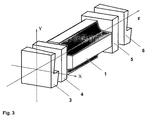
- FIG. 3 For this purpose, an embodiment is given, with which it is possible to adapt linearly polarized laser light in accordance with the predetermined by the electro-optical element 1 polarization conditions.
- the polarization system consists of the phase converter 3 for generating the elliptical polarization with predetermined orientation distribution of the Indikatrixellipsen. Furthermore, a quarter-wave plate 4 is used, which converts the elliptically polarized light in each linearly polarized light components.
- n e is the extraordinary and n 0 the ordinary refractive index of the crystal.
- the surface of the phase converter 3 thus forms part of a helical surface.
- ⁇ ⁇ + 4 ⁇ ⁇ N ,
- the ellipse of the polarization of the light is oriented so that one of its axes is parallel to the polarization plane of the incident light.
- the quarter wave plate 4 inserted beyond the polarization converter, whose major axes are parallel to the axes of the polarization ellipse, converts the elliptically polarized light into linearly polarized light.
- the light polarization plane at the output has an angle which is equal to half of the phase shift ⁇ / 2 with respect to its original direction and thus agrees with (10).
- the disks are inserted into an immersion liquid.
- the dielectric embedding means can also be used to increase the operating voltage at the electrodes. This makes it possible to increase the adjustment range of the opening angle many times.
Landscapes
- Physics & Mathematics (AREA)
- Nonlinear Science (AREA)
- General Physics & Mathematics (AREA)
- Optics & Photonics (AREA)
- Chemical & Material Sciences (AREA)
- Engineering & Computer Science (AREA)
- Ceramic Engineering (AREA)
- Crystallography & Structural Chemistry (AREA)
- Optical Modulation, Optical Deflection, Nonlinear Optics, Optical Demodulation, Optical Logic Elements (AREA)
- Optical Couplings Of Light Guides (AREA)
- Led Device Packages (AREA)
Abstract
Description
- Die Erfindung bezieht sich auf eine Vorrichtung zur Erzeugung eines Bessel-Lichtstrahlenbündels mit wenigstens einem elektrooptischen Element, das über eine Lichtein- und Lichtaustrittsoberfläche verfügt, die sich jeweils längs einer das elektrooptische Element durchsetzenden optischen Achse gegenüberliegen und das in Längserstreckung zur optischen Achse eine das elektrooptische Element seitlich begrenzende Mantelfläche vorsieht.
- Bessel-Lichtstrahlenbündel zeichnen sich durch ihre quasi-beugungsfreien Eigenschaften aus, bei denen die Lichtenergie längs des sehr dünnen Strahls mit in Strahlausbreitungsrichtung relativ konstanter und geringer Querabmessung gebündelt wird. Näheres zu den Grundlagen von Bessel-Lichtstrahlenbündel findet sich in Artikeln von J. Durnin, "Exact solutions for nondiffracting beams: I. The scalar theory", J. Opt. Soc. Am. A, 4 (1987) pp. 651-654 oder J. Durnin, J. J. Miceli, and J. H. Eberly, "Diffraction-free beams", Phys. Rev. Lett 58, (1987) S. 1499-1501.
- Bessel-Lichtstrahlenbündel werden in vielen Anwendungen der linearen und nichtlinearen Optik, bspw. zu Zwecken der Frequenzkonversion oder als Pumplichtstrahlen zur Induzierung spezieller optischer Effekte eingesetzt, siehe auch V. N. Belyi, N. S. Kazak, N. A. Khilo, "Frequency conversion of Bessel light beams in nonlinear crystals", Quantum Electronics 30 (2000) S. 753-766 oder N. A. Khilo, R. V. Chulkov, V. N. Belyi, N. S. Kazak, A. S. Grabtchikov, and V. A. Orlovich, "Properties of Raman stokes light generated by a zero-order Bessel pump beam", Preprint Nr. 740, B. I. Stepanov Institute of Physics of Belarus, Minsk, S. 65.
- Bessel-Lichtstrahlenbündel weisen eine ringförmige Lichtintensitätsverteilung auf, wobei die Wellenvektoren des Lichtstrahles auf einem Kegel liegen. Daher werden für die Strahlerzeugung entsprechende rotationssymmetrische optische Elemente, wie Hologramme, Axicone oder asphärische Linsen eingesetzt, die in der Lage sind ebene Wellenfronten eines parallel verlaufenden Lichtstrahls in einen Lichtstrahl mit ringförmigem Strahlquerschnitt umzuformen.
- Die meistgebrauchten optischen Elemente für die Erzeugung von Bessel-Lichtbündel 0ter Ordnung sind kegelförmige Linsen, so genannte Axicone. Der Brechungswinkel dieser Elemente ist konstant, wodurch auch die Konstanz des Konvergenzwinkels der Wellenvektoren des Lichtbündels in Strahlrichtung hinter dem Axicon gewährleistet wird.
- Nachteil der gegenwärtig verwendeten Axicone ist, dass ihre optischen Eigenschaften unveränderlich sind. In vielen praktischen Anwendungen besteht der Wunsch und die Notwendigkeit, die Strahleigenschaften eines Bessel-Lichtstrahlenbündels während des Einsatzes zu ändern. Hierzu gilt es einen Satz von Axiconlinsen mit unterschiedlichen Öffnungswinkeln bereitzuhalten, die bedarfsweise in den Strahlengang eines optischen Systems zur Erzeugung von Bessel-Lichtstrahlenbündel einzusetzen sind. Der Wechsel der Linsen nimmt erhebliche Zeit für Ein- und Ausbau sowie für eine Neujustage in Anspruch.
- Manchmal erfordern Anwendungen auch zwei möglichst gleiche Axicone, zum Beispiel zur Durchführung der Lichtschnittmethode an zylinderförmigen Objekten, siehe hierzu den Beitrag von T. Dresel, J. Schwider, A. Wehrhahn, S. Babin, "Grazing incidence interferometry applied to the measurement of cylindrical surfaces", Optical Engineering 34 (1995), S. 3531-3535. Hierbei kommen zwei gleichartige Axicone zur Vermeidung einer sich ausbildenden räumlichen Modulation des Interferenzbildes ohne Objekt zum Einsatz. Die Fertigung von exakt baugleichen Axiconen führt jedoch auf große technische Probleme und hohen Aufwand. Wünschenswert wäre dagegen ein einziges Axicon, das sich im Betrieb schnell und einfach optisch durchsteuern ließe.
- Aus der Literatur ist ferner eine Anordnung bekannt, bei der sich ein Axicon zwischen zwei Sammellinsen befindet. Hierbei läuft ein Ausgangsstrahlenbündel mit einem Gauß'schen Strahlprofil durch die erste Sammellinse und wandelt sich in der Brennebene dieser Linse, in der sich das Axicon befindet in einen Lichtkreis um. Die zweite Linse konvertiert die ringförmige Feldverteilung in das Bessel-Lichtstrahlenbündel. Bei Variation der Position des zwischen beiden Sammellinsen befindlichen Axicons ändert sich der Radius in der Brennebene der ersten Linse und damit der effektive Öffnungswinkel des Bessel-Lichtstrahlenbündels. Die Verstellgeschwindigkeit einer derartigen Anordnung ist jedoch nicht besonders hoch. Näheres hierzu findet sich in dem Artikel von S. Klewitz, F. Brinkmann, S. Herminghaus, and P. Leiderer, "Bessel-beam pumped tunable distributed-feedback laser", Appl. Opt. 34 (1995) S. 7670-7673.
- Die größte Verstellgeschwindigkeit mit der die optischen Eigenschaften von Axiconen beeinflussbar sind bieten optische Systeme, die auf der Brechungsindexänderung unter Einfluss eines elektrischen Feldes basieren. Die unmittelbare Einwirkung des elektrischen Feldes auf die elektrooptischen Eigenschaften eines optischen Mediums und dementsprechend auf die Ausbreitungsrichtung der Lichtstrahlen beim Durchtritt durch derartige Medien schließt den Faktor der mechanischen Trägheit aus, der die Frequenzantwort von Vorrichtungen wie vorstehend beschrieben begrenzt. So weisen diese Systeme den weiteren Vorteil auf, dass sie sich einfach mit anderen Systemkomponenten elektrisch synchronisieren lassen.
- In einem Beitrag von V. Leparskiy, A. Mashenko, "Elektrooptische kegelförmige Linsen für die Bildung von Bessel Lichtstrahlenbündel", Izvestija der Staatsuniversität F. Skoriny, Gomel (2001(6)) S. 9-12, wird ein Weg aufgezeigt, wie mit Hilfe eines nichtlinearen elektrooptischen Kristalls die optischen Eigenschaft eines Axicons nachgebildet sowie dessen Abbildungseigenschaften zugleich variabel eingestellt werden können. Von zentraler Bedeutung hierbei ist die Nutzung des linearen elektrooptischen Effektes oder auch Pockels-Effekt genannt, der zu einer Brechungsindexänderung innerhalb des durchstrahlten Mediums führt. Der Pockels-Effekt tritt ausgeprägt in Kristallen mit nicht-zentrischer Symmetrie auf.
- Damit sich ein optisch nichtlinearer Kristall in derselben Weise wie ein Axicon auf ein einfallendes Lichtstrahlenbündel auswirkt, ist beim linearen elektrooptischen Effekt eine der Radialkoordinate proportionale Änderung der elektrischen Feldstärke erforderlich. Die lineare Verteilung elektrischer Felder wird mit Hilfe eines Systems von Flächenelektroden erzeugt. Das optische System besteht hierbei aus einer planparallelen Kristallplatte, wobei auf einer Oberfläche der Kristallplatte transparente Elektroden in Form von konzentrischen Kreisen aufgebracht sind. Auf der anderen Oberfläche befindet sich eine feste Elektrode. Durch einen speziellen Spannungsteiler werden die kreisförmigen Elektroden so mit Spannung versorgt, dass sich als Funktion des Abstandes r vom Zentrum ein Potential Ur/R ergibt, wobei U die Potentialdifferenz zwischen den äußeren Elektroden und R deren Abstand vom Zentrum ist. Die Mittelelektrode liegt dabei auf gleichem Potenzial wie die Außenelektrode. Verwendet man zum Beispiel einen Lithiumniobat-Kristall, dessen optische Achse mit der Systemachse zusammenfällt, so ist bei einer Steuerspannung von 10 kV und einem Lichtbündeldurchmesser von 5 mm das System einem Axicon aus normalem Glas mit einem Öffnungswinkel von 4,5' äquivalent.
- Der Erfindung liegt die Aufgabe zugrunde eine Vorrichtung zur Erzeugung eines Bessel-Lichtstrahlenbündels mit wenigstens einem elektrooptischen Element, das über eine Lichtein- und Lichtaustrittsoberfläche verfügt, die sich jeweils längs einer das elektrooptische Element durchsetzenden optischen Achse gegenüberliegen und das in Längserstreckung zur optischen Achse eine das elektrooptische Element seitlich begrenzende Mantelfläche vorsieht, derart weiterzubilden, dass eine möglichst einfache, kostengünstige und kompakte Anordnung geschaffen werden soll, mit der die Erzeugung von Bessel-Lichtstrahlenbündel mit variablen Öffnungswinkeln über einen großen Bereich möglich sein soll. Die Variation des Öffnungswinkels soll darüber hinaus schnell in Verstellzeiten von unter 10-8 s erfolgen und dies und ohne die Bewegungen mechanischer Komponenten.
- Die Lösung der der Erfindung zugrunde liegenden Aufgabe ist im Anspruch 1 angegeben. Den Erfindungsgedanken vorteilhaft weiterbildende Merkmale sind Gegenstand der Unteransprüche sowie der Beschreibung insbesondere unter Bezugnahme auf die Ausführungsbeispiele zu entnehmen.
- Lösungsgemäß zeichnet sich eine Vorrichtung zur Erzeugung eines Bessel-Lichtstrahlenbündels mit wenigstens einem elektrooptischen Element, das über eine Lichtein- und Lichtaustrittsoberfläche verfügt, die sich jeweils längs einer das elektrooptische Element durchsetzenden optischen Achse gegenüberliegen und das in Längserstreckung zur optischen Achse eine das elektrooptische Element seitlich begrenzende Mantelfläche vorsieht, dadurch aus, dass Flächenelektroden derart ausgebildet und längs der Mantelfläche angeordnet sind, dass bei Applikation einer elektrischen Spannung an die Flächenelektroden im Inneren des elektrooptischen Elementes ein elektrisches Feld generierbar ist, dessen zur optischen Achse radial orientierter Feldstärkeverlauf sich linear proportional mit dem radialen Abstand zur optischen Achse ändert. Hierbei durchläuft ein in ein Bessel-Lichtstrahlenbündel umzuwandelnder Lichtstrahl längs der optischen Achse des elektrooptischen Elementes, das vorzugsweise aus einem 3m-Kristall, bspw. Litiumniobat-Kristall, besteht, und tritt über die Lichteintrittsoberfläche in das elektrooptische Element ein. Die Lichteintrittsoberfläche weist hierbei keine Lichtverluste verursachenden Strukturen auf und verfügt vorzugsweise über eine die Reflexionsverluste minimierende Beschichtung. Auch ist es alternativ oder in Kombination möglich die Lichteintrittsoberfläche unter dem Brewster-Winkel zum einfallenden Lichtstrahl zu neigen, um auf diesen Weise Reflexionsverluste auszuschließen oder zumindest zu reduzieren.
- Innerhalb des elektrooptischen Elementes erfährt der einfallende Lichtstrahl im Wege der Wechselwirkung mit den optisch anisotropen Brechungseigenschaften des elektrooptischen Elementes eine Formumwandlung, die sich in Abhängigkeit des das im Inneren des elektrooptischen Elementes vorherrschenden elektrischen Potenzials und die damit verbundene Auswirkung auf die Anisotropie der Brechkraft individuell vorgebbar einstellen lässt. So kann der Öffnungswinkel des letztlich aus dem elektrooptischen Element durch die Lichtaustrittsoberfläche austretenden Bessel-Lichtstrahlenbündels individuell durch Vorgabe des im Inneren des Elementes vorherrschenden elektrischen Potenzials und die damit verbundene Brechkraftverteilung eingestellt werden. Die für die Steuerung des Öffnungswinkels nötige räumliche Variation der Brechkraft bzw. des Brechungsindex kann vorzugsweise mit einem Quadrupolfeld erzeugt werden, das im Weiteren unter Bezugnahme auf die in den Figuren dargestellten Ausführungsbeispielen näher erläutert wird.
- Die Erfindung wird nachstehend ohne Beschränkung des allgemeinen Erfindungsgedankens anhand von Ausführungsbeispielen unter Bezugnahme auf die Zeichnungen exemplarisch beschrieben. Es zeigen:
- Fig. 1
- Darstellung eines elektrooptischen Elementes mit seitlich an der Mantelfläche des Elementes vorgesehenen Flächenelektroden zur Erzeugung eines Quadrupolfeldes
- Fig. 2 a, b
- Darstellung einer räumlich verteilten Polarisation eines Eingangslichtbündels, das für eine Umformung in ein Bessel-Lichtstrahlenbündel erforderlich ist: a) N ungradzahlig, b) N gradzahlig
- Fig. 3
- Anordnung, die ein Bessel-Lichtstrahlbündel nullter Ordnung aus linear polarisierter Strahlung erzeugt.
- In
Figur 1 ist ein elektrooptisches Element 1 dargestellt, das eine räumlich geradprismatische Raumform aufweist und über eine Lichtein-(1') und Lichtaustrittsfläche (1") verfügt. Es sei angenommen, dass die zeichnerische Z-Achse sowohl der Lichtausbreitungsrichtung durch das Element 1, als auch der optischen Achse des elektrooptischen Elements 1 entspricht. Die das elektrooptische Element 1 seitlich begrenzende Mantelfläche M weist zudem vier hyperbelartig gekrümmte Flächenbereiche auf, in denen zur Ausbildung von Flächenelektroden 2 elektrisch leitendes Material, vorzugsweise ein Form einer Metallbeschichtung vorgesehen ist. Die hyperbelartig gekrümmten Flächenbereiche sind allesamt gleichförmig ausgebildet und verlaufen längs zur optischen Achse zueinander parallel. Zwischen jeweils zwei benachbarten Flächenelektroden 2 sind unbeschichtete Mantelflächenbereiche 2', durch die die jeweiligen Flächenelektroden voneinander elektrisch isoliert sind. - Wie bereits erwähnt eignen sich Kristalle der Klasse 3m besonders gut für die Ausbildung einer lösungsgemäßen Vorrichtung, allen voran Lithiumniobat. Auch eignen sich KD*P oder LBO-Kristalle. Der Kristall wird derart angeordnet, so dass sich Licht entlang der optisch drei zähligen Achse ausbreiten kann. Die Flächenelektroden 2 werden mit jeweils abwechselnden Polaritäten gemäß der Bilddarstellung in
Figur 1 mit elektrischem Potenzial versorgt, so dass sich im Inneren des Kristalls 1 ein Quadrupolfeld E ausbilden kann. Hierbei liegt der Vektor des elektrischen Feldes E auf der zur optischen Achse senkrechten Ebene. Mit Hilfe der hyperbelförmigen Flächenelektroden 2, deren Form in der angegebenen x-y-Ebene durch die Gleichung
gegeben ist, bildet sich in einem zylindrischen Bereich mit einem Radius R0 ein inhomogenes elektrisches Feld mit dem Potenzial
aus, wobei ϕ0 die Potentialdifferenz zwischen den Flächenelektroden und R0 der Abstand zwischen dem Mittelpunkt und den Elektroden sind. - Die elektrische Feldstärke in der Achsenrichtungen OX und OY beträgt dabei

- Bei einer derartigen Kopplungsgeometrie tritt in Kristallen der Klasse 3m der doppelt transversale Pockelseffekt. auf. Eine Besonderheit dieses Phänomens ist, dass die optischen Indikatrixkoeffizienten in jedem Punkt der Apertur nicht nur von der Amplitude des elektrischen Feldes E, sondern auch von dessen Richtung abhängen.
- Der Querschnitt der optischen Indikatrix ist eine Ellipse, deren Hauptachse bezüglich der Achsen OX und OY um den Winkel β gedreht ist, mit

- Die Änderung des Brechungsindex entlang der Ellipsenhauptrichtungen der einzelnen räumlich verteilten, der Indikatrix zuordenbaren Ellipsen ist durch die Beziehung

gegeben, wobei E=(Ex 2+Ey 2)1/2, n0 der Brechungsindex des ungestörten Kristalls, rij der elektrooptische Koeffizient (für den Fall eines Lithiumniobatkristalls gilt rij=r22) ist. - Durch Einsetzen der Ausdrücke für den Feldanteil (3) in (5) erhält man:

wobei ρ die radiale Koordinate ist. Aus Gleichung (6) sieht man, dass beim Anlegen der Spannung an die Flächenelektroden der Zusammenhang zwischen Brechungsindex und Koordinate linear ist. Die induzierte Veränderung des Brechungsindex führt zur Ablenkung der durch den Kristall transmittierten Lichtstrahlbündel in radialer Richtung. Im Rahmen der paraxialen Näherung kann man den Strahlablenkungswinkel aus der Relation
ermitteln. Bei der linearen Änderung des Brechungsindex des Mediums bleibt die Größe 1/n0(dn/dρ) konstant. Setzt man (6) in (7) ein, erhält man nach Integration
wobei L die Länge der elektrooptisch wirksamen Zone ist. - Das Ergebnis (8) definiert den Winkel α', um den der Strahl nach Durchlaufen der Zone der Länge L abgelenkt wird. Beim Austritt des Strahls aus dem Kristall wird der Winkel in n0 wegen der Brechung in der Planfläche höher und liegt bei

wobei D die Apertur des Einfallsbündels ist. - Nach (9) ist der Ablenkungswinkel des Axicons dem elektrooptischen Koeffizienten r22, der Systemlänge L und der an den Elektroden anliegenden Potenzialdifferenz ϕ0 proportional sowie umgekehrt proportional dem Quadrat der Apertur D.
- Wie oben erwähnt hängen die Orientierung der Polarisationsellipse und die Koeffizienten der optischen Indikatrix über den Kristallquerschnitt mit dem Komponentenverhältnis Ex und Ey zusammen. Setzt man die Größe der Komponenten Ex und Ey aus (3) in die Beziehung (4) ein, erhält man

wobei ψ der Winkel zwischen der radialen Linie zwischen dem Koordinatennullpunkt und der Achse OX ist und N eine beliebige ganze Zahl. Wenn N geradzahlig ist, hat der Zielstrahl eine bestimmte Polarisationsrichtung, wenn N ungeradzahlig ist, hat er die dazu orthogonale Polarisation. Dieser Zusammenhang ist in denFiguren 2 a und b näher illustriert. Es sei angenommen, dass in denFiguren 2 a und b jeweils der Querschnitt des Lichtstrahls innerhalb des elektrooptischen Kristalls dargestellt ist. Für eine wunschgemäße Formgebung des den Kristall durchdringenden Lichtstrahles gilt es die Polarisationseigenschaften des Lichtstrahlenbündels in der gesamten Apertur der seitens der optischen Indikatrix vorgegebenen Ellipsenachsen anzupassen. InFigur 2 a sei N geradzahlig gewählt. Die Ellipsenachsen der Indikatrix bei unterschiedlichen Rotationswinkeln ψ sind am peripheren Umfangsrand der Apertur ersichtlich. So dreht sich die Ellipsenachse der optischen Indikatrix bei Änderung des Seitenwinkels ψ, wodurch sich der Brechungsindex des Kristalls linear ändert, der zudem nicht von der Größe des Elektrodenpotenzials abhängt. - Für einen konstanten Winkel ψ bleibt der Drehwinkel der Indikatrix gleich, siehe
Figur 2a . So weisen die längs des eingetragenen Radialstrahls dargestellten Ellipsen, die den Indikatrixellipsen entsprechen eine einheitliche Achsenlage auf. Aus diesem Grund ist das System für Licht, dessen Polarisation in jedem Punkt der Apertur mit der passenden Indikatrixachse zusammenfällt, einem Axicon mit dem Öffnungswinkel γ gleich, wobei für den Öffnungswinkel γ gilt:
- Um mit dem lösungsgemäß ausgebildeten elektrooptischen Element ein Bessel-Lichtstrahlenbündel zu erzeugen, gilt es daher den in das Element eintretenden Lichtstrahl mit Polarisationseigenschaften auszustatten, die zu den Achsen der optischen Indikatrix des elektrooptischen Elementes korrespondieren.
- Normalerweise sind Laserstrahlen linear polarisiert, so dass die gewünschte Funktion der bisher diskutierten Anordnung noch nicht gegeben ist. Um die benötigte Verteilung der Lichtpolarisation über den Querschnitt des auf den Kristall einfallenden Lichtstrahlbündels sicherzustellen, wie dies in den
Figuren 2 a und b illustriert ist, sind zusätzliche optische Maßnahmen zu treffen. - In
Figur 3 ist hierzu ein Ausführungsbeispiel angegeben, mit dem es möglich ist, linear polarisiertes Laserlicht an entsprechend den durch das elektrooptische Element 1 vorgegebenen Polarisationsverhältnisse anzupassen. - Das Polarisationssystem besteht aus dem Phasenwandler 3 für die Erzeugung der elliptischen Polarisation mit vorgegebener Orientierungsverteilung der der Indikatrixellipsen. Weiterhin wird eine Viertelwellenplatte 4 verwendet, die das elliptisch polarisierte Licht in jeweils linear polarisierte Lichtanteile konvertiert.
- Der Phasenwandler 3 basiert aus einer Scheibe aus einem einachsigen Kristalls, bei der eine Seite eben ist, und die andere Seite so gestaltet wird, dass sich die Scheibendicke b linear im Bereich einer Umdrehung als Funktion des Winkels ψ von bo nach b0+λ/(ne-no) ändert, d. h.

- Hierbei ist ne der außerordentliche und n0 der ordentliche Brechungsindex des Kristalls.
- Die Oberfläche des Phasenwandlers 3 bildet somit einen Teil einer Schraubenfläche.
- Jede doppelbrechende Platte, deren Hauptachse einen Winkel von 45° mit dem elektrischen Feldvektor des auf die Platte 3 einfallenden Lichtbündels einnimmt, ruft eine relative Phasenverschiebung von Γ=2πb(ne-no)/λ zwischen den Hauptbestandteilen des Lichtbündels hervor. Im beschriebenen Fall ergibt sich unter Berücksichtigung von (12)

- Die Ellipse der Lichtpolarisation ist dabei so orientiert, dass eine ihrer Achsen der Polarisationsebene des einfallenden Lichts parallel ist. Die jenseits des Polarisationswandlers eingesetzte Viertelwellenplatte 4, deren Hauptachsen den Achsen der Polarisationsellipse parallel sind, formt das elliptisch polarisierte Licht in linear polarisiertes Licht um. Dabei hat die Lichtpolarisationsebene am Ausgang einen Winkel, der der Hälfte der Phasenverschiebung Γ/2 bezüglich seiner ursprünglichen Richtung gleich ist und stimmt damit mit (10) überein.
- Zur Beseitigung möglicher Brechungserscheinungen an der Phasenwandlerscheibe 3 bzw. 4 sind die Scheiben in eine Immersionsflüssigkeit eingesetzt. Das dielektrische Einbettungsmittel kann auch zur Erhöhung der Betriebsspannung an den Elektroden genutzt werden. Das ermöglicht es, den Verstellbereich des Öffnungswinkels um ein Mehrfaches zu vergrößern.
- Falls für die weitere Anwendung am Lichtaustritt linear polarisiertes Licht erforderlich ist, wird am Ausgang des elektrooptisch steuerbaren Elements gemäß
Figur 3 noch eine weitere Polarisationswandleranordnung 5+6 vorgesehen die sich im Wesentlichen aus den gleichen optischen Phasenwandlern 5, 6 zusammensetzt wie die bereits beschriebenen Phasenwandler 3, 4 am Lichteintritt. - Denkbar ist auch die Anwendung anderer Methoden zur Polarisationswandlung, so beispielsweise der Einsatz eines biaxialen Kristalls.
- Mithin können folgende Vorteile für die lösungsgemäße Anordnung gegenüber dem bis anhin bekannten Stand der Technik genannten werden:
- Es wird ein elektrisch steuerbares Axicon anstelle eines mechanisch gesteuerten Axicons vorgeschlagen. Die damit ausgeschlossene mechanische Trägheit ermöglicht es, den Öffnungswinkel in einem wesentlich erweiterten Frequenzbereich zu steuern.
- Eine spezielle Anordnung zur Erzeugung der Eingangspolarisation für das strahlablenkende Element wurde vorgeschlagen
- Eine besondere Einfachheit der Synchronisation mit anderen Hochgeschwindigkeitsprozessen und- vorrichtungen wurde erreicht.
- Berechnungen haben gezeigt, dass für einen Lithiumniobat-Kristall bei einer Apertur des Lichtbündels von D= 5 mm und einer Kristalllänge von L = 10 cm der Öffnungswinkel nicht mehr als 20' bei einer Steuerspannung von 10 kV beträgt.
-
- 1
- Elektrooptisches Element
- 1'
- Lichteintrittsfläche
- 1"
- Lichtaustrittsfläche
- 2
- Flächenelektroden
- 2'
- Elektrisch isolierende Mantelfläche
- 3
- Phasenwandler
- 4
- Lambda / 4- Plättchen
- 5
- Lambda / 4- Plättchen
- 6
- Phasenwandler
Claims (15)
- Vorrichtung zur Erzeugung eines Bessel-Lichtstrahlenbündels mit wenigstens einem elektrooptischen Element, das über eine Lichtein- und Lichtaustrittsoberfläche verfügt, die sich jeweils längs einer das elektrooptische Element durchsetzenden optischen Achse gegenüberliegen und das in Längserstreckung zur optischen Achse eine das elektrooptische Element seitlich begrenzende Mantelfläche vorsieht,
dadurch gekennzeichnet, dass Flächenelektroden derart ausgebildet und längs der Mantelfläche angeordnet sind, dass bei Applikation einer elektrischen Spannung an die Flächenelektroden im Inneren des elektrooptischen Elementes ein elektrisches Feld generierbar ist, dessen zur optischen Achse radial orientierter Feldstärkeverlauf sich linear proportional mit dem radialen Abstand zur optischen Achse ändert. - Vorrichtung nach Anspruch 1,
dadurch gekennzeichnet, dass das elektrooptische Element ein optisch nicht linearer Kristall mit trigonaler Kristallstruktur, vorzugsweise ein Lithiumniobatkristall, ADP, KD*P, BBO ist. - Vorrichtung nach Anspruch 1 oder 2,
dadurch gekennzeichnet, dass das elektrooptische Element eine Querschnittsfläche vorsieht, die senkrecht zur optischen Achse des elektrooptischen Elementes orientiert ist,
dass die Querschnittsfläche von einer in der Mantelfläche enthaltenden Mantellinie begrenzt ist, die in wenigstens vier Bereiche jeweils hyperbelförmig gekrümmt ist, dass die hyperbelförmigen Bereiche eine jeweils zur optischen Achse konkav abgewandte Krümmung aufweisen, und
dass die hyperbelförmig ausgebildeten Mantellinienbereiche gleich verteilt um die optische Achse angeordnet sind. - Vorrichtung nach Anspruch 3,
dadurch gekennzeichnet, dass die Flächenelektroden als elektrisch leitende Materialschichten ausgebildet sind, die jeweils ausschließlich in Bereichen der Mantelfläche vorgesehen sind, die hyperbelförmig gekrümmt sind. - Vorrichtung nach Anspruch 3 oder 4,
dadurch gekennzeichnet, dass die die Flächenelektroden in Umfangsrichtung längs der Mantelfläche elektrisch voneinander isoliert sind. - Vorrichtung nach einem der Ansprüche 1 bis 5,
dadurch gekennzeichnet, dass wenigstens vier Flächenelektroden zur Erzeugung eines elektrischen Quadrupolfeldes an der Mantelfläche des elektrooptischen Elementes angeordnet sind. - Vorrichtung nach Anspruch 6,
dadurch gekennzeichnet, dass die Flächenelektroden jeweils gleichförmig und gleichgroß ausgebildet sind und in Umfangsrichtung gleich verteilt um die optische Achse angeordnet sind. - Vorrichtung nach einem der Ansprüche 1 bis 7,
dadurch gekennzeichnet, dass das elektrooptische Element längs zur optischen Achse eine Längserstreckung mit gleich bleibendem Querschnitt aufweist. - Vorrichtung nach einem der Ansprüche 1 bis 8,
dadurch gekennzeichnet, dass längs der optischen Achse außerhalb des elektrooptischen Elementes ein optisches Lichtphasenwandlersystem vorgesehen ist, das von linear polarisiertem Licht durchsetzbar ist, wobei die Polarisationseigenschaften des Lichtstrahls in Abhängigkeit einer innerhalb des elektrooptischen Elementes vorherrschenden Indikatrix derart anpassbar sind, dass die Polarisation des Lichtstrahls in jedem Punkt der Apertur, d.h. der von dem Lichtstrahl in dem elektrooptischen Element beleuchteten Querschnittsfläche, mit der Indikatrix zuordenbaren Achsen zusammenfällt. - Vorrichtung nach Anspruch 9,
dadurch gekennzeichnet, dass das Lichtphasenwandlersystem wenigstens einen ersten und zweiten Phasenwandler vorsieht,
dass der zweite Phasenwandler zwischen dem ersten Phasenwandler und der Lichteintrittsfläche des elektrooptischen Elements angebracht ist,
dass der erste Phasenwandler linear polarisiertes Licht in elliptisch polarisiertes Licht mit innerhalb der Apertur des Lichtstrahles vorgebbarer Orientierungsverteilung der Ellipsenachsen, und
dass der zweite Phasenwandler als λ/4-Wellenplatte ausgebildet ist, die elliptisch polarisiertes Licht in linear polarisiertes Licht konvertiert. - Vorrichtung nach Anspruch 10,
dadurch gekennzeichnet, dass der erste Phasenwandler als spiralförmige Phasenplatte ausgebildet ist, bei der eine Oberfläche in Arte einer Schraubenfläche ausgebildet ist. - Vorrichtung nach Anspruch 10 oder 11,
dadurch gekennzeichnet, dass zumindest der erste Phasenwandler aus einem gyrotropen kubischen Kristall besteht, vorzugsweise eines Sillent-Typs. - Vorrichtung nach einem der Ansprüche 10 bis 12,
dadurch gekennzeichnet, dass zumindest zwischen dem Lichtphasenwandlersystem und dem elektrooptischen Element eine Immersionsflüssigkeit zur Beseitigung von Brechungseffekten vorgesehen ist. - Vorrichtung nach Anspruch 13,
dadurch gekennzeichnet, dass die Immersionsflüssigkeit eine dielektrische Flüssigkeit ist und die Mantelfläche des elektrooptischen Elementes zumindest benetzt. - Vorrichtung nach Anspruch 9,
dadurch gekennzeichnet, dass das optische Lichtphasenwandlersystem aus einem biaxialen Kristall besteht.
Applications Claiming Priority (1)
| Application Number | Priority Date | Filing Date | Title |
|---|---|---|---|
| DE102006056022A DE102006056022A1 (de) | 2006-11-28 | 2006-11-28 | Vorrichtung zur Erzeugung eines Bessel-Lichtstrahlbündels mit wenigstens einem elektrooptischen Element |
Publications (3)
| Publication Number | Publication Date |
|---|---|
| EP1927884A2 true EP1927884A2 (de) | 2008-06-04 |
| EP1927884A3 EP1927884A3 (de) | 2009-05-27 |
| EP1927884B1 EP1927884B1 (de) | 2010-11-03 |
Family
ID=39144493
Family Applications (1)
| Application Number | Title | Priority Date | Filing Date |
|---|---|---|---|
| EP07017481A Not-in-force EP1927884B1 (de) | 2006-11-28 | 2007-09-06 | Vorrichtung zur Erzeugung eines Bessel-Lichtstrahlenbündels mit wenigstens einem elektrooptischen Element |
Country Status (3)
| Country | Link |
|---|---|
| EP (1) | EP1927884B1 (de) |
| AT (1) | ATE487158T1 (de) |
| DE (2) | DE102006056022A1 (de) |
Families Citing this family (1)
| Publication number | Priority date | Publication date | Assignee | Title |
|---|---|---|---|---|
| CN111999901A (zh) * | 2020-06-23 | 2020-11-27 | 南开大学 | 一种产生多波段消色差贝塞尔光束的超表面轴锥器件 |
Citations (1)
| Publication number | Priority date | Publication date | Assignee | Title |
|---|---|---|---|---|
| US3575486A (en) | 1969-08-25 | 1971-04-20 | Victor M De Posada | Specimen moving attachment for a microscope or the like |
Family Cites Families (4)
| Publication number | Priority date | Publication date | Assignee | Title |
|---|---|---|---|---|
| US3575487A (en) * | 1969-09-17 | 1971-04-20 | Bell Telephone Labor Inc | Two-coordinate quadrupole optical deflector |
| US3650602A (en) * | 1970-08-19 | 1972-03-21 | Honeywell Inc | Parallel array light beam deflector with variable phase plate |
| JPH11259895A (ja) * | 1998-03-09 | 1999-09-24 | Fuji Electric Co Ltd | 多層記録用光ヘッド |
| US6473246B1 (en) * | 1999-07-09 | 2002-10-29 | Advanced Optical Technologies, Inc. | Electro-optical light beam deflector |
-
2006
- 2006-11-28 DE DE102006056022A patent/DE102006056022A1/de not_active Withdrawn
-
2007
- 2007-09-06 DE DE502007005540T patent/DE502007005540D1/de active Active
- 2007-09-06 EP EP07017481A patent/EP1927884B1/de not_active Not-in-force
- 2007-09-06 AT AT07017481T patent/ATE487158T1/de active
Patent Citations (1)
| Publication number | Priority date | Publication date | Assignee | Title |
|---|---|---|---|---|
| US3575486A (en) | 1969-08-25 | 1971-04-20 | Victor M De Posada | Specimen moving attachment for a microscope or the like |
Non-Patent Citations (5)
| Title |
|---|
| J. DURNIN: "Exact solutions for nondiffracting beams: I. The scalar theory", J. OPT. SOC. AM. A, vol. 4, 1987, pages 651 - 654 |
| J. DURNIN; J. J. MICELI; J. H. EBERLY: "Diffraction-free beams", PHYS. REV. LETT, vol. 58, 1987, pages 1499 - 1501 |
| S. KLEWITZ; F. BRINKMANN; S. HERMINGHAUS; P. LEIDERER: "Bessel-beam pumped tunable distributed-feedback laser", APPL. OPT., vol. 34, 1995, pages 7670 - 7673 |
| T. DRESEL; J. SCHWIDER; A. WEHRHAHN; S. BABIN: "Grazing incidence interferometry applied to the measurement of cylindrical surfaces", OPTICAL ENGINEERING, vol. 34, 1995, pages 3531 - 3535 |
| V. N. BELYI; N. S. KAZAK; N. A. KHILO: "Frequency conversion of Bessel light beams in nonlinear crystals", QUANTUM ELECTRONICS, vol. 30, 2000, pages 753 - 766 |
Also Published As
| Publication number | Publication date |
|---|---|
| EP1927884A3 (de) | 2009-05-27 |
| ATE487158T1 (de) | 2010-11-15 |
| DE102006056022A1 (de) | 2008-05-29 |
| EP1927884B1 (de) | 2010-11-03 |
| DE502007005540D1 (de) | 2010-12-16 |
Similar Documents
| Publication | Publication Date | Title |
|---|---|---|
| DE3523641C1 (de) | Einrichtung zum Selektieren von rotationssymmetrischen Polarisationskomponenten einesLichtbuendels und Verwendung einer solchen Einrichtung | |
| DE69227270T2 (de) | Poyntingvektorablenkungskompensation in Typ-II-Phasenanpassung | |
| DE2855841C2 (de) | ||
| DE2947730C2 (de) | Optischer Zirkulator | |
| DE2640865A1 (de) | Verfahren und vorrichtung zum beugen eines lichtstrahls | |
| DE1541725A1 (de) | Magisches Tee mit Gitter | |
| DE1000061B (de) | Verfahren zur Beeinflussung von Hochfrequenzschwingungen mit Hilfe magnetischer oder elektrischer Felder | |
| EP3479162A1 (de) | Anordnung zur erzeugung eines bessel-strahls | |
| DE102020200798A1 (de) | Verfahren und Vorrichtung zur Lasermaterialbearbeitung mittels eines in seinem Leistungsprofil verstellbaren Bearbeitungslaserstrahls | |
| DE2804442A1 (de) | Laservorrichtung fuer einschliessende wellen im fernen infrarotbereich | |
| EP1927884B1 (de) | Vorrichtung zur Erzeugung eines Bessel-Lichtstrahlenbündels mit wenigstens einem elektrooptischen Element | |
| DE3506271A1 (de) | Verfahren und vorrichtung zum fokussieren und defokussieren eines millimeterwellenlaengestrahlungsbuendels | |
| DE1283963B (de) | Verfahren zur steuerbaren Richtungsablenkung optischer Strahlung, insbesondere von Laser-Strahlung, und Vorrichtung zur Durchfuehrung desselben | |
| DE4434921C2 (de) | Achromatisches Phasenverzögerungselement | |
| DE2160044A1 (de) | Akustisch-optische Filtervorrichtung | |
| DE60022081T2 (de) | Nichtlineare optische körper und vorrichtungen | |
| DE2021204C3 (de) | Vorrichtung zur Beugung von Licht mittels Schallwellen | |
| DE102017116477B4 (de) | Polarisationswandler mit reflektiver Axikonoptik, Laseroptik, und Verfahren zur Herstellung eines Polarisationswandlers | |
| DE2758876A1 (de) | Vorrichtung zur frequenzumsetzung von kohaerentem licht | |
| DE1924994C3 (de) | Dielektrischer Wellenleiter | |
| EP1405136B1 (de) | Ablenkeinrichtung zur ablenkung elektromagnetischer wellen und optisches element hierfür | |
| DE19832647C1 (de) | Verfahren zur Erzeugung Gaußscher Intensitätsverteilungen im Strahlprofil einer durch Frequenzverdopplung erzeugten Strahlung | |
| DE4415511B4 (de) | Laseranordnung zur Kompensation der Doppelbrechung und der Bifokussierung in Lasermedien | |
| DE102014118880A1 (de) | Optische Einrichtung zur Modulation der spektralen Phase von Laserpulsen | |
| DE2009556C3 (de) | Verfahren und Vorrichtung zum Steuern der Ablenkung eines Lichtstrahls |
Legal Events
| Date | Code | Title | Description |
|---|---|---|---|
| PUAI | Public reference made under article 153(3) epc to a published international application that has entered the european phase |
Free format text: ORIGINAL CODE: 0009012 |
|
| AK | Designated contracting states |
Kind code of ref document: A2 Designated state(s): AT BE BG CH CY CZ DE DK EE ES FI FR GB GR HU IE IS IT LI LT LU LV MC MT NL PL PT RO SE SI SK TR |
|
| AX | Request for extension of the european patent |
Extension state: AL BA HR MK RS |
|
| PUAL | Search report despatched |
Free format text: ORIGINAL CODE: 0009013 |
|
| AK | Designated contracting states |
Kind code of ref document: A3 Designated state(s): AT BE BG CH CY CZ DE DK EE ES FI FR GB GR HU IE IS IT LI LT LU LV MC MT NL PL PT RO SE SI SK TR |
|
| AX | Request for extension of the european patent |
Extension state: AL BA HR MK RS |
|
| RIC1 | Information provided on ipc code assigned before grant |
Ipc: G02F 1/03 20060101AFI20080312BHEP Ipc: G02F 1/29 20060101ALI20090417BHEP |
|
| 17P | Request for examination filed |
Effective date: 20091127 |
|
| AKX | Designation fees paid |
Designated state(s): AT BE BG CH CY CZ DE DK EE ES FI FR GB GR HU IE IS IT LI LT LU LV MC MT NL PL PT RO SE SI SK TR |
|
| 17Q | First examination report despatched |
Effective date: 20100324 |
|
| GRAP | Despatch of communication of intention to grant a patent |
Free format text: ORIGINAL CODE: EPIDOSNIGR1 |
|
| GRAS | Grant fee paid |
Free format text: ORIGINAL CODE: EPIDOSNIGR3 |
|
| GRAA | (expected) grant |
Free format text: ORIGINAL CODE: 0009210 |
|
| AK | Designated contracting states |
Kind code of ref document: B1 Designated state(s): AT BE BG CH CY CZ DE DK EE ES FI FR GB GR HU IE IS IT LI LT LU LV MC MT NL PL PT RO SE SI SK TR |
|
| REG | Reference to a national code |
Ref country code: GB Ref legal event code: FG4D |
|
| REG | Reference to a national code |
Ref country code: CH Ref legal event code: EP |
|
| REG | Reference to a national code |
Ref country code: IE Ref legal event code: FG4D Free format text: LANGUAGE OF EP DOCUMENT: GERMAN |
|
| REF | Corresponds to: |
Ref document number: 502007005540 Country of ref document: DE Date of ref document: 20101216 Kind code of ref document: P |
|
| REG | Reference to a national code |
Ref country code: CH Ref legal event code: NV Representative=s name: RENTSCH & PARTNER |
|
| REG | Reference to a national code |
Ref country code: NL Ref legal event code: T3 |
|
| LTIE | Lt: invalidation of european patent or patent extension |
Effective date: 20101103 |
|
| PG25 | Lapsed in a contracting state [announced via postgrant information from national office to epo] |
Ref country code: LT Free format text: LAPSE BECAUSE OF FAILURE TO SUBMIT A TRANSLATION OF THE DESCRIPTION OR TO PAY THE FEE WITHIN THE PRESCRIBED TIME-LIMIT Effective date: 20101103 |
|
| REG | Reference to a national code |
Ref country code: IE Ref legal event code: FD4D |
|
| PG25 | Lapsed in a contracting state [announced via postgrant information from national office to epo] |
Ref country code: FI Free format text: LAPSE BECAUSE OF FAILURE TO SUBMIT A TRANSLATION OF THE DESCRIPTION OR TO PAY THE FEE WITHIN THE PRESCRIBED TIME-LIMIT Effective date: 20101103 Ref country code: IS Free format text: LAPSE BECAUSE OF FAILURE TO SUBMIT A TRANSLATION OF THE DESCRIPTION OR TO PAY THE FEE WITHIN THE PRESCRIBED TIME-LIMIT Effective date: 20110303 Ref country code: SI Free format text: LAPSE BECAUSE OF FAILURE TO SUBMIT A TRANSLATION OF THE DESCRIPTION OR TO PAY THE FEE WITHIN THE PRESCRIBED TIME-LIMIT Effective date: 20101103 Ref country code: BG Free format text: LAPSE BECAUSE OF FAILURE TO SUBMIT A TRANSLATION OF THE DESCRIPTION OR TO PAY THE FEE WITHIN THE PRESCRIBED TIME-LIMIT Effective date: 20110203 Ref country code: PT Free format text: LAPSE BECAUSE OF FAILURE TO SUBMIT A TRANSLATION OF THE DESCRIPTION OR TO PAY THE FEE WITHIN THE PRESCRIBED TIME-LIMIT Effective date: 20110303 Ref country code: LV Free format text: LAPSE BECAUSE OF FAILURE TO SUBMIT A TRANSLATION OF THE DESCRIPTION OR TO PAY THE FEE WITHIN THE PRESCRIBED TIME-LIMIT Effective date: 20101103 Ref country code: SE Free format text: LAPSE BECAUSE OF FAILURE TO SUBMIT A TRANSLATION OF THE DESCRIPTION OR TO PAY THE FEE WITHIN THE PRESCRIBED TIME-LIMIT Effective date: 20101103 |
|
| PG25 | Lapsed in a contracting state [announced via postgrant information from national office to epo] |
Ref country code: GR Free format text: LAPSE BECAUSE OF FAILURE TO SUBMIT A TRANSLATION OF THE DESCRIPTION OR TO PAY THE FEE WITHIN THE PRESCRIBED TIME-LIMIT Effective date: 20110204 |
|
| REG | Reference to a national code |
Ref country code: CH Ref legal event code: PFA Owner name: FRAUNHOFER-GESELLSCHAFT ZUR FOERDERUNG DER ANGEWA Free format text: FRAUNHOFER-GESELLSCHAFT ZUR FOERDERUNG DER ANGEWANDTEN FORSCHUNG E.V.#HANSASTRASSE 27C#80686 MUENCHEN (DE) -TRANSFER TO- FRAUNHOFER-GESELLSCHAFT ZUR FOERDERUNG DER ANGEWANDTEN FORSCHUNG E.V.#HANSASTRASSE 27C#80686 MUENCHEN (DE) |
|
| PG25 | Lapsed in a contracting state [announced via postgrant information from national office to epo] |
Ref country code: CZ Free format text: LAPSE BECAUSE OF FAILURE TO SUBMIT A TRANSLATION OF THE DESCRIPTION OR TO PAY THE FEE WITHIN THE PRESCRIBED TIME-LIMIT Effective date: 20101103 Ref country code: EE Free format text: LAPSE BECAUSE OF FAILURE TO SUBMIT A TRANSLATION OF THE DESCRIPTION OR TO PAY THE FEE WITHIN THE PRESCRIBED TIME-LIMIT Effective date: 20101103 Ref country code: IE Free format text: LAPSE BECAUSE OF FAILURE TO SUBMIT A TRANSLATION OF THE DESCRIPTION OR TO PAY THE FEE WITHIN THE PRESCRIBED TIME-LIMIT Effective date: 20101103 Ref country code: ES Free format text: LAPSE BECAUSE OF FAILURE TO SUBMIT A TRANSLATION OF THE DESCRIPTION OR TO PAY THE FEE WITHIN THE PRESCRIBED TIME-LIMIT Effective date: 20110214 |
|
| PG25 | Lapsed in a contracting state [announced via postgrant information from national office to epo] |
Ref country code: PL Free format text: LAPSE BECAUSE OF FAILURE TO SUBMIT A TRANSLATION OF THE DESCRIPTION OR TO PAY THE FEE WITHIN THE PRESCRIBED TIME-LIMIT Effective date: 20101103 Ref country code: DK Free format text: LAPSE BECAUSE OF FAILURE TO SUBMIT A TRANSLATION OF THE DESCRIPTION OR TO PAY THE FEE WITHIN THE PRESCRIBED TIME-LIMIT Effective date: 20101103 Ref country code: RO Free format text: LAPSE BECAUSE OF FAILURE TO SUBMIT A TRANSLATION OF THE DESCRIPTION OR TO PAY THE FEE WITHIN THE PRESCRIBED TIME-LIMIT Effective date: 20101103 Ref country code: SK Free format text: LAPSE BECAUSE OF FAILURE TO SUBMIT A TRANSLATION OF THE DESCRIPTION OR TO PAY THE FEE WITHIN THE PRESCRIBED TIME-LIMIT Effective date: 20101103 |
|
| PLBE | No opposition filed within time limit |
Free format text: ORIGINAL CODE: 0009261 |
|
| STAA | Information on the status of an ep patent application or granted ep patent |
Free format text: STATUS: NO OPPOSITION FILED WITHIN TIME LIMIT |
|
| 26N | No opposition filed |
Effective date: 20110804 |
|
| REG | Reference to a national code |
Ref country code: DE Ref legal event code: R082 Ref document number: 502007005540 Country of ref document: DE |
|
| REG | Reference to a national code |
Ref country code: DE Ref legal event code: R097 Ref document number: 502007005540 Country of ref document: DE Effective date: 20110804 |
|
| PG25 | Lapsed in a contracting state [announced via postgrant information from national office to epo] |
Ref country code: IT Free format text: LAPSE BECAUSE OF FAILURE TO SUBMIT A TRANSLATION OF THE DESCRIPTION OR TO PAY THE FEE WITHIN THE PRESCRIBED TIME-LIMIT Effective date: 20101103 |
|
| BERE | Be: lapsed |
Owner name: FRAUNHOFER-GESELLSCHAFT ZUR FORDERUNG DER ANGEWAN Effective date: 20110930 |
|
| PG25 | Lapsed in a contracting state [announced via postgrant information from national office to epo] |
Ref country code: MC Free format text: LAPSE BECAUSE OF NON-PAYMENT OF DUE FEES Effective date: 20110930 |
|
| PG25 | Lapsed in a contracting state [announced via postgrant information from national office to epo] |
Ref country code: BE Free format text: LAPSE BECAUSE OF NON-PAYMENT OF DUE FEES Effective date: 20110930 |
|
| PG25 | Lapsed in a contracting state [announced via postgrant information from national office to epo] |
Ref country code: MT Free format text: LAPSE BECAUSE OF FAILURE TO SUBMIT A TRANSLATION OF THE DESCRIPTION OR TO PAY THE FEE WITHIN THE PRESCRIBED TIME-LIMIT Effective date: 20101103 |
|
| PG25 | Lapsed in a contracting state [announced via postgrant information from national office to epo] |
Ref country code: LU Free format text: LAPSE BECAUSE OF NON-PAYMENT OF DUE FEES Effective date: 20110906 Ref country code: CY Free format text: LAPSE BECAUSE OF EXPIRATION OF PROTECTION Effective date: 20101103 |
|
| PG25 | Lapsed in a contracting state [announced via postgrant information from national office to epo] |
Ref country code: TR Free format text: LAPSE BECAUSE OF FAILURE TO SUBMIT A TRANSLATION OF THE DESCRIPTION OR TO PAY THE FEE WITHIN THE PRESCRIBED TIME-LIMIT Effective date: 20101103 |
|
| PG25 | Lapsed in a contracting state [announced via postgrant information from national office to epo] |
Ref country code: HU Free format text: LAPSE BECAUSE OF FAILURE TO SUBMIT A TRANSLATION OF THE DESCRIPTION OR TO PAY THE FEE WITHIN THE PRESCRIBED TIME-LIMIT Effective date: 20101103 |
|
| REG | Reference to a national code |
Ref country code: AT Ref legal event code: MM01 Ref document number: 487158 Country of ref document: AT Kind code of ref document: T Effective date: 20120906 |
|
| PG25 | Lapsed in a contracting state [announced via postgrant information from national office to epo] |
Ref country code: AT Free format text: LAPSE BECAUSE OF NON-PAYMENT OF DUE FEES Effective date: 20120906 |
|
| REG | Reference to a national code |
Ref country code: FR Ref legal event code: PLFP Year of fee payment: 9 |
|
| PGFP | Annual fee paid to national office [announced via postgrant information from national office to epo] |
Ref country code: CH Payment date: 20150922 Year of fee payment: 9 Ref country code: GB Payment date: 20150922 Year of fee payment: 9 Ref country code: DE Payment date: 20150923 Year of fee payment: 9 |
|
| PGFP | Annual fee paid to national office [announced via postgrant information from national office to epo] |
Ref country code: FR Payment date: 20150923 Year of fee payment: 9 |
|
| PGFP | Annual fee paid to national office [announced via postgrant information from national office to epo] |
Ref country code: NL Payment date: 20150923 Year of fee payment: 9 |
|
| REG | Reference to a national code |
Ref country code: DE Ref legal event code: R119 Ref document number: 502007005540 Country of ref document: DE |
|
| REG | Reference to a national code |
Ref country code: CH Ref legal event code: PL |
|
| REG | Reference to a national code |
Ref country code: NL Ref legal event code: MM Effective date: 20161001 |
|
| GBPC | Gb: european patent ceased through non-payment of renewal fee |
Effective date: 20160906 |
|
| PG25 | Lapsed in a contracting state [announced via postgrant information from national office to epo] |
Ref country code: NL Free format text: LAPSE BECAUSE OF NON-PAYMENT OF DUE FEES Effective date: 20161001 |
|
| REG | Reference to a national code |
Ref country code: FR Ref legal event code: ST Effective date: 20170531 |
|
| PG25 | Lapsed in a contracting state [announced via postgrant information from national office to epo] |
Ref country code: FR Free format text: LAPSE BECAUSE OF NON-PAYMENT OF DUE FEES Effective date: 20160930 Ref country code: GB Free format text: LAPSE BECAUSE OF NON-PAYMENT OF DUE FEES Effective date: 20160906 Ref country code: CH Free format text: LAPSE BECAUSE OF NON-PAYMENT OF DUE FEES Effective date: 20160930 Ref country code: DE Free format text: LAPSE BECAUSE OF NON-PAYMENT OF DUE FEES Effective date: 20170401 Ref country code: LI Free format text: LAPSE BECAUSE OF NON-PAYMENT OF DUE FEES Effective date: 20160930 |