EP1927837A2 - Impact detection system - Google Patents
Impact detection system Download PDFInfo
- Publication number
- EP1927837A2 EP1927837A2 EP07122009A EP07122009A EP1927837A2 EP 1927837 A2 EP1927837 A2 EP 1927837A2 EP 07122009 A EP07122009 A EP 07122009A EP 07122009 A EP07122009 A EP 07122009A EP 1927837 A2 EP1927837 A2 EP 1927837A2
- Authority
- EP
- European Patent Office
- Prior art keywords
- optical fiber
- impact
- subject
- arithmetic processing
- fiber sensors
- Prior art date
- Legal status (The legal status is an assumption and is not a legal conclusion. Google has not performed a legal analysis and makes no representation as to the accuracy of the status listed.)
- Granted
Links
Images




Classifications
-
- G—PHYSICS
- G01—MEASURING; TESTING
- G01M—TESTING STATIC OR DYNAMIC BALANCE OF MACHINES OR STRUCTURES; TESTING OF STRUCTURES OR APPARATUS, NOT OTHERWISE PROVIDED FOR
- G01M11/00—Testing of optical apparatus; Testing structures by optical methods not otherwise provided for
- G01M11/08—Testing mechanical properties
- G01M11/083—Testing mechanical properties by using an optical fiber in contact with the device under test [DUT]
Definitions
- the present invention relates to an impact detection system using an optical fiber sensor.
- CFRP carbon fiber reinforced plastic
- Japanese Patent Application Laid-Open Publication No. 2005-098 921 describes a damage detecting apparatus using a fiber Bragg grating (FBG) optical fiber sensor.
- FBG fiber Bragg grating
- the invention described in the Japanese Patent Application Laid-Open Publication No. 2005-098 921 detects the damage of a composite material on the basis of a change of the output of characteristic detecting means by vibrating the composite material with a piezo-element.
- That invention uses the following components for the detection of the damage: the piezo-element fixed to be disposed at a predetermined position of a composite structure; a lead wire to transmit a signal to the piezo-element; the optical fiber sensor fixedly disposed so that the composite material constituting the composite structure is put between the optical fiber sensor and the piezo-element, which sensor has a grating portion reflecting light of a predetermined wavelength on a core portion; a light source performing the radiation of light to a core portion; and the characteristic detecting means for detecting the characteristics of the reflected light from the grating portion. Moreover, a spectrum analyzer or the like to detect the frequency characteristic of the reflected light from the grating portion is used as the characteristic detecting means.
- an impact detection system in order to attain the above object, includes: three or more optical fiber sensors disposed respectively in different positions of a subject to be inspected, the sensors not being in alignment with one another, in which the optical fiber sensors each includes a core portion to have a grating portion formed therein, the grating portion has a plurality of gratings reflecting light so that a wavelength band of reflected light changes when a distance between adjacent gratings changes, and the optical fiber sensor vibrates the wavelength band depending on an elastic wave propagating through the subject; a light source to input light into the core portion, in which a spectrum bandwidth of the light includes at least a desired vibration width of the wavelength band; two or more optical filters connected to an output end of the optical fiber sensor, the optical filters having different pass bands to one another with respect to an output light of one of the optical fiber sensors; and an arithmetic processing apparatus to perform arithmetic processing of output values of the three or more optical fiber sensors through the optical filters so as to specify a position on the
- FIG. 1 is a schematic configuration diagram of an impact detection system 10 to perform the detection of an impact to a composite structure Z.
- the composite structure Z is used as a subject to be inspected.
- the impact detection system 10 of the present embodiment is equipped with optical fiber sensors 30 installed at predetermined positions of the composite structure Z, in which the detection of an impact 21 is to be performed, by being embedded or stuck; a spectrum analyzer 42 to detect the wavelength characteristics of reflected lights obtained from the optical fiber sensors 30; and an arithmetic processing apparatus 50 to performing the arithmetic processing of an output value of the spectrum analyzer 42.
- a power supply device 43 of the spectrum analyzer 42 is shown.
- the three or more, or the four or more, optical fiber sensors 30 are disposed at different positions being not on a straight line, although they are not shown.
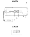
- Each of the optical fiber sensors 30 is a fiber Bragg grating (FBG) optical fiber sensor. As shown in the schematic configuration diagram of FIG. 2A , each of the optical fiber sensors 30 includes a grating portion 33 reflecting light having a predetermined wavelength in the core portion 32 of the optical fiber sensor 30 to be formed as an optical fiber 34.
- FBG fiber Bragg grating
- the optical fiber 34 is connected to the spectrum analyzer 42 at one end of the optical fiber 34, and irradiating lights covering the whole wavelength band of a predetermined range are entered into the core portion 32 by the light source provided in the spectrum analyzer 42.
- the lights entering from the spectrum analyzer 42 propagate through the core portion 32, and lights having only a part of wavelengths of the entering lights are reflected at the grating portion 33.
- FIG. 2B is a diagram showing the changes of a refraction index of the core portion 32 in the traveling direction of light, and a range L in the figure shows the refraction index in the grating portion 33.
- the grating portion 33 is formed so as to change the refraction index of the core portion 32 at a fixed period.
- the grating portion 33 selectively reflects only the light having a specific wavelength at the boundary parts where the refraction index changes. If a disturbance, such as strain caused by a vibration, is applied to the grating portion 33, then the grating intervals thereof change (expansion or contraction), and the wavelength of the reflected light thereby changes.
- the wavelength change ⁇ B of a reflected light of an FBG optical fiber sensor can here be expressed by the following formula, where n denotes the effective refractive index of the core, ⁇ denotes a grating interval, P 11 and P 12 denote Pockels coefficients, ⁇ denotes a Poisson ratio, ⁇ denotes applied strain, ⁇ denotes the temperature coefficient of the fiber material, and ⁇ T denotes a temperature change (see Alan D. Kersey, "Fiber Grating Sensors," JOURNAL OF LIGHTWAVE TECHNOLOGY, Vol. 15, No. 8, 1997 ).
- ⁇ ⁇ ⁇ B 2 ⁇ n ⁇ ⁇ ⁇ 1 - n 2 2 ⁇ P 12 - ⁇ ⁇ P 11 + P 12 ⁇ ⁇ + ⁇ + dn dT n ⁇ ⁇ ⁇ T
- the strain amount ⁇ of the grating portion 33 changes, and the wavelength of a reflected light changes according to the strain amount ⁇ as a result. If a vibration is transmitted from the vibration source in a good condition, then the grating portion 33 is greatly distorted, and the change ⁇ B of the wavelength greatly changes. Moreover, if a vibration is not transmitted from the vibration source in a good condition, the grating portion 33 is small distorted, and the change ⁇ B of the wavelength small changes.
- FIG. 3A shows a configuration example of an optical fiber sensor and the spectrum analyzer 42 connected to it.
- the spectrum analyzer 42 includes a light source 61, an optical circulator 62, an arrayed waveguide grating (AWG) module 63, and a photoelectric transducer 60.
- AWG arrayed waveguide grating
- the optical fiber 34 that comprises four optical fiber sensors 30a to 30d that have different reflection wavelengths from one another and are connected in series is connected to the spectrum analyzer 42.
- optical fiber sensors 30 As the minimum configuration, three optical fiber sensors 30 are required.
- the optical fiber sensors 30 formed in series as one optical fiber may be used as the present configuration example, or three or more optical fiber sensors formed as an independent plural optical fibers may be used.
- the light source 61 is a wide band light source including a desired vibration band of reflection wavelengths of the optical fiber sensors 30a to 30d.
- the reflection wavelength characteristic of an optical fiber sensor changes to the outside of the wavelength band of the light source, no reflected lights are produced.
- the wavelength band of the light source limits the detection range of vibrations. It is preferable to set the light source to have a sufficiently wide band in order that a perfect reflected light is always emitted even if the reflection wavelengths of the optical fiber sensors 30a to 30d vibrate by an impact.
- the vibration band of the reflection wavelengths of an optical fiber sensor depends on the characteristics of the optical fiber sensor, an impact, the quality of the material of a subject to be inspected.
- the optical circulator 62 causes light from the light source 61 to travel to the side of the optical fiber sensors 30a to 30d, and guides the reflected lights from the optical fiber sensors 30a to 30d to the input port P0 of the AWG module 63.
- the reflected light guided by the optical circulator 62 is introduced into the input port P0 of the AWG module 63 by an optical fiber 69.
- the AWG module 63 includes an AWG board 64.
- a lightwave circuit monolithically integrated on a glass substrate by the technique of the optical waveguide is formed on the AWG board 64.
- the lightwave circuit on the AWG board 64 includes input and output slab waveguides 65 and 66, an arrayed waveguide 67, and an output waveguide 68, and constitutes eight optical filters that are connected to the input port P0 in parallel with one another and have different pass bands from one another.
- the lightwave circuit on the AWG board 64 separates the multiplexed-wavelength input light, into the lights having respective wavelengths, by distributing the input light to pass it through the eight optical filters, and outputs the lights in parallel with one another to eight output ports P1 to P8.
- the number of the output ports in practical use is not limited to eight.
- the pass bands of the respective optical filters corresponding to the eight output ports P1 to P8 are shown in the spectrum diagram of FIG. 3B .
- an optical filter passes the reflected light corresponding to the part in FIG. 3B in which the reflected light input distribution 70 of the reflected light from the optical fiber sensor 30b having a center wavelength ⁇ 2 overlaps with a pass band 71 of the optical filter, and outputs the passed reflected light to the output port P3.
- another optical filter passes the reflected light corresponding to the part in which the reflected light overlaps with a pass band 72, and outputs the passed reflected light to the output port P4.
- the optical filter made to correspond to the one optical fiber sensor 30b may be set as two optical filters corresponding to the output ports P3 and P4, or may be set as, for example, the three output ports P3 to P5 or the five output ports P2 to P6.
- the number and the distribution of the optical fibers made to correspond to one optical fiber sensor are set in view of the fact that the vibration band of the reflection wavelength of an optical fiber sensor depends on an unknown impact,.
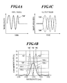
- an input distribution 73T of the reflected light from the optical fiber sensor 30 appears.
- an elastic wave from an impact position as a vibration source propagates through the composite structure Z, and the optical fiber sensor 30 vibrates the wavelength of the reflected light output according to the elastic wave propagating through the composite structure Z.
- the vibration of the wavelength is shown as an input wave 73 W of FIG. 4A .
- the reflected light input distribution 73T shown in FIG. 4B shifts to a higher level and a lower level alternately to minutely vibrate and the value of the wavelength repeats increase and decrease.
- 73C in the Figure denotes the vibration center of the center wavelength of the reflected light input distribution 73T.
- the center wavelength 75C of the pass band 75T of one optical filter is fixed in a higher area relative to the vibration center 73C.
- the center wavelength 74C of the pass band 74T of the other optical filter is fixed in a lower area relative to the vibration center 73C.
- the lower side slope 75T-1 of the higher pass band 75T intersect with the higher side slope 73T-1 of the reflected light input distribution 73T.
- the higher side slope 74T-1 of the lower pass band 74T intersects with the lower side slope 74T-2 of the reflected light input distribution 73T.
- the wavelength vibrations of a reflected light can be detected at a high sensitivity by fixing the pass bands 75T and 74T in the aforesaid positional relation to the reflected light input distribution 73T.
- the higher optical filter passes the reflected light corresponding to the part in which the reflected light input distribution 73T overlaps with the pass band 75T, and outputs the passed reflected light.
- the lower optical filter passes the reflection light corresponding to the part in which the reflected light input distribution 73T overlaps with the pass band 74T, and output the passed reflected light.
- the output waves 74W and 75W become the waves having the phase in an inverse relation to each other.
- the input wave 73W depends on an impact.
- the method of disposing two or more optical filters having different pass bands on each of the higher side and the lower side may be adopted.
- the plurality of optical filters having the configuration mentioned above is made to correspond to each of the necessary three or more optical fiber sensors.
- the necessary number of the channels of the AWG module 63 and the necessary number of the AWG modules 63 are provided.
- the spectrum analyzer 42 shown in FIG. 3A outputs light waves to the output ports P1 to P8 on the basis of the principle mentioned above, and the photoelectric transducer 60 converts the light waves into electric signals to output them to the outside.
- the outputs of the spectrum analyzer 42 receive the A/D conversion through a not shown interface, and are input into the arithmetic processing apparatus 50.
- the arithmetic processing apparatus 50 performs the arithmetic processing for calculating the position and the magnitude of an impact by the following method 1, method 2, or the other methods on the basis of the output values of the spectrum analyzer 42. Moreover, the arithmetic processing apparatus 50 performs the recording of the operation results.
- the arithmetic processing apparatus 50 of the present embodiment comprises an electronic computer.
- the arithmetic processing apparatus 50 comprises, for example, a central processing unit (CPU) performing arithmetic processing in conformity with a program; a read only memory (ROM) storing the program; a random access memory (RAM) storing input value data from the spectrum analyzer 42, and the data in the operation processes in conformity with the program and the data of operation results; an interface performing the transmission and the reception of data with spectrum analyzer 42; an image output interface converting the display data of the operation results into an image signal of a suitable format to output the converted image signal to a display monitor; and a data bus performing the transmission of various instructions and data among the respective components mentioned above.
- CPU central processing unit
- ROM read only memory
- RAM random access memory
- optical fiber sensors 30e, 30f, and 30g are installed in a structuring composite material Z at three different points not on a straight line.
- a vibration generated by an impact propagates through the structure as a wave.
- the wave propagating at this time comprises an So wave (P wave) arriving at the optical fiber sensors 30 precedently and an A 0 wave (S wave) arriving at the optical sensors 30 lately. Because the two waves have different propagation speeds, a difference is produced between their arrival times.
- each of the waves can individually be identified even if the difference between the arrival times is little.
- the propagation distances of the waves that is, the distances between the impact 21 and each sensor, can be calculated on the basis of the obtained difference between the arrival times and the known propagation speed difference.
- the arithmetic processing apparatus 50 calculates propagation distances L1, L2, and L3 from the unknown impact 21 to each of the optical fiber sensors 30e, 30f, and 30g on the basis of the input data from the spectrum analyzer 42 by the principle described above.
- the arithmetic processing apparatus 50 performs the analysis processing with the data of the elastic waves obtained by the detection with each of the optical fiber sensors 30e, 30f, and 30g to calculate the difference between the arrival times of the So wave and the A 0 wave, and multiplies the difference by the known propagation speed difference to calculate the propagation distances L1, L2, and L3 from the impact 21 to each of the optical fiber sensors 30e, 30f, and 30g.
- the arithmetic processing apparatus 50 performs the operations of identifying the intersection point of three circles C1, C2, and C3 having radii of propagation distances L1, L2, and L3, respectively, from the centers of the optical fiber sensors 30e, 30f, and 30g, respectively, as the position of the impact 21.
- the detection values of four or more optical fiber sensors 30 may be used in order to enhance the precision and the like.
- the arithmetic processing apparatus 50 calculates the vibration energy of the elastic wave detected by the optical fiber sensor 30g on the basis of the input value data from the spectrum analyzer 42. Furthermore, the arithmetic processing apparatus 50 calculates the magnitude of the impact on the basis of the propagation distance L3 nearest to the impact and the magnitude of the vibration energy of the elastic wave detected by the optical fiber sensor 30g corresponding to the distance L3. The detection values of two or more optical fiber sensors 30 may be used for the calculation of the magnitude of the impact.
- the method of using four optical fiber sensors is described as another method with reference to FIG. 6 .
- the optical fiber sensors 30e, 30f, 30g, and 30h are installed in the structuring composite material Z at different four points.
- the arithmetic processing apparatus 50 measures the arrival time of the elastic wave (for example, So wave) having the same propagation speed from the vibration source of the impact 21 as for each of the four optical fiber sensors 30e, 30f, 30g, and 30h. That is, the arithmetic processing apparatus 50 performs the analysis processing with the data of the elastic wave obtained by the detection by each of the optical fiber sensors 30e, 30f, 30g, and 30h to calculates the arrival time of the elastic wave (for example, So wave).
- the arithmetic processing apparatus 50 performs the analysis processing with the data of the elastic wave obtained by the detection by each of the optical fiber sensors 30e, 30f, 30g, and 30h to calculates the arrival time of the elastic wave (for example, So wave).
- the arithmetic processing apparatus 50 calculates the difference of each arrival time between the optical fiber sensor 30h, at which the elastic wave has arrived at the earliest time, and each of the other three optical fiber sensors 30e, 30f, and 30g. Furthermore, the arithmetic processing apparatus 50 multiplies the obtained arrival time difference by the known propagation speed to calculate the object propagation distances L1, L2, and L3 of the elastic wave.
- the arithmetic processing apparatus 50 performs the operation for identifying the center of the common circumcircle C0 of the three circles C1, C2, and C3 having the centers of the optical fiber sensors 30e, 30f, and 30g, respectively, and the radii of the propagation distances L1, L2, and L3, respectively, as the position of the impact 21.
- the arithmetic processing apparatus 50 calculates the vibration energy of the elastic wave detected with the optical fiber sensor 30h on the basis of the input value data from the spectrum analyzer 42.
- the arithmetic processing apparatus 50 calculates the magnitude of the impact on the basis of the magnitude of the vibration energy detected with the nearest optical fiber sensor 30h and the radius of the circle C0 obtained by the above impact position identifying operation.
- the detection values of more optical fiber sensors 30 may be used in order to heighten the precision and the like.
- the position, or the position and the magnitude, of an impact loaded on a subject to be inspected can be detected by the use of the optical fiber sensors.
- the optical fiber sensors are used, the sensors can easily be installed in a subject to be inspected of the airframe of an airplane or the like by being embedded or by being pasted, and the existence of an impact can immediately be judged independently of the state of the subject such as moving or stopping.
- the position, or the position and the magnitude, of the impact can be detected, and they can be informed to an operator or another system to be utilized for safe operating.
- the operator and the other system can expect damage or destruction and can measure the necessity of the search and the inspection of them by knowing the position, or the position and the magnitude, of the impact.
- the history of impact loading can be utilized for the life expectation of the subject and the accident analysis thereof, which can be utilized for the safe operation.
- the information of an elastic wave can correctly be obtained, and the accuracy of specifying the existence, the position, and the magnitude of an impact can be enhanced.
Landscapes
- Chemical & Material Sciences (AREA)
- Analytical Chemistry (AREA)
- Physics & Mathematics (AREA)
- General Physics & Mathematics (AREA)
- Length Measuring Devices By Optical Means (AREA)
- Optical Transform (AREA)
- Length Measuring Devices Characterised By Use Of Acoustic Means (AREA)
- Testing Of Optical Devices Or Fibers (AREA)
- Force Measurement Appropriate To Specific Purposes (AREA)
Abstract
Description
- The present invention relates to an impact detection system using an optical fiber sensor.
- In a field in which both the strength and the weight saving of a material of, for example, the airframe of an airplane are required, it is indispensable to widely apply a composite material such as a carbon fiber reinforced plastic (CFRP) in order to meet the requirement of this kind.
- As an apparatus for performing the detection of damage, a defect, and the like, of such a composite material,
Japanese Patent Application Laid-Open Publication No. 2005-098 921 - The invention described in the
Japanese Patent Application Laid-Open Publication No. 2005-098 921 - That invention uses the following components for the detection of the damage: the piezo-element fixed to be disposed at a predetermined position of a composite structure; a lead wire to transmit a signal to the piezo-element; the optical fiber sensor fixedly disposed so that the composite material constituting the composite structure is put between the optical fiber sensor and the piezo-element, which sensor has a grating portion reflecting light of a predetermined wavelength on a core portion; a light source performing the radiation of light to a core portion; and the characteristic detecting means for detecting the characteristics of the reflected light from the grating portion. Moreover, a spectrum analyzer or the like to detect the frequency characteristic of the reflected light from the grating portion is used as the characteristic detecting means.
- However, the invention described in the
Japanese Patent Application Laid-Open Publication No. 2005-098 921 - It is, therefore, a main object of the present invention to configure an impact detection system using an optical fiber sensor.
- According to a first aspect of the invention, in order to attain the above object, an impact detection system includes: three or more optical fiber sensors disposed respectively in different positions of a subject to be inspected, the sensors not being in alignment with one another, in which the optical fiber sensors each includes a core portion to have a grating portion formed therein, the grating portion has a plurality of gratings reflecting light so that a wavelength band of reflected light changes when a distance between adjacent gratings changes, and the optical fiber sensor vibrates the wavelength band depending on an elastic wave propagating through the subject; a light source to input light into the core portion, in which a spectrum bandwidth of the light includes at least a desired vibration width of the wavelength band; two or more optical filters connected to an output end of the optical fiber sensor, the optical filters having different pass bands to one another with respect to an output light of one of the optical fiber sensors; and an arithmetic processing apparatus to perform arithmetic processing of output values of the three or more optical fiber sensors through the optical filters so as to specify a position on the subject where an impact is loaded, the output values being obtained when the impact is loaded on the subject.
- The above and other objects, advantages and features of the present invention will become more fully understood from the detailed description given hereinbelow and the appended drawings which are given by way of illustration only, and thus are not intended as a definition of the limits of the present invention, and wherein:
- FIG. 1
- is a schematic configuration diagram of an impact detection system according to an embodiment of the present invention;
- FIG. 2A
- is a schematic configuration diagram of an optical fiber sensor;
- FIG. 2B
- is a diagram showing the changes of the refraction index of a grating portion in the traveling direction of light;
- FIG. 3A
- is a configuration diagram showing the optical fiber sensor and a spectrum analyzer connected to the sensor;
- FIG. 3B
- is a spectrum diagram showing the pass bands of eight optical filters;
- FIG. 4A
- is a diagram showing the waveform of an input wave into the optical filter;
- FIG. 4B
- is a spectrum diagram showing the pass band of two optical filters;
- FIG. 4C
- is a diagram showing the waveforms of output waves of the optical filters;
- FIG. 5
- is a plan view for illustrating one method for identifying an impact position according to one embodiment of the present invention; and
- FIG. 6
- is a plan view for illustrating another method for identifying the impact position according to the one embodiment of the present invention.
- In the following, one embodiment of the present invention is described with reference to the attached drawings. The following is one embodiment of the present invention and does not limit the present invention.
-
FIG. 1 is a schematic configuration diagram of animpact detection system 10 to perform the detection of an impact to a composite structure Z. In the present embodiment, the composite structure Z is used as a subject to be inspected. - As shown in
FIG. 1 , theimpact detection system 10 of the present embodiment is equipped withoptical fiber sensors 30 installed at predetermined positions of the composite structure Z, in which the detection of animpact 21 is to be performed, by being embedded or stuck; aspectrum analyzer 42 to detect the wavelength characteristics of reflected lights obtained from theoptical fiber sensors 30; and anarithmetic processing apparatus 50 to performing the arithmetic processing of an output value of thespectrum analyzer 42. - Moreover, a
power supply device 43 of thespectrum analyzer 42 is shown. The three or more, or the four or more,optical fiber sensors 30 are disposed at different positions being not on a straight line, although they are not shown. - Each of the
optical fiber sensors 30 is a fiber Bragg grating (FBG) optical fiber sensor. As shown in the schematic configuration diagram ofFIG. 2A , each of theoptical fiber sensors 30 includes agrating portion 33 reflecting light having a predetermined wavelength in thecore portion 32 of theoptical fiber sensor 30 to be formed as anoptical fiber 34. - The
optical fiber 34 is connected to thespectrum analyzer 42 at one end of theoptical fiber 34, and irradiating lights covering the whole wavelength band of a predetermined range are entered into thecore portion 32 by the light source provided in thespectrum analyzer 42. The lights entering from thespectrum analyzer 42 propagate through thecore portion 32, and lights having only a part of wavelengths of the entering lights are reflected at thegrating portion 33. -
FIG. 2B is a diagram showing the changes of a refraction index of thecore portion 32 in the traveling direction of light, and a range L in the figure shows the refraction index in thegrating portion 33. - As shown in the figure, the
grating portion 33 is formed so as to change the refraction index of thecore portion 32 at a fixed period. Thegrating portion 33 selectively reflects only the light having a specific wavelength at the boundary parts where the refraction index changes. If a disturbance, such as strain caused by a vibration, is applied to thegrating portion 33, then the grating intervals thereof change (expansion or contraction), and the wavelength of the reflected light thereby changes. - The wavelength change ΔλB of a reflected light of an FBG optical fiber sensor can here be expressed by the following formula, where n denotes the effective refractive index of the core, Λ denotes a grating interval, P11 and P12 denote Pockels coefficients, ν denotes a Poisson ratio, ε denotes applied strain, α denotes the temperature coefficient of the fiber material, and ΔT denotes a temperature change (see Alan D. Kersey, "Fiber Grating Sensors," JOURNAL OF LIGHTWAVE TECHNOLOGY, Vol. 15, No. 8, 1997).

- Consequently, when a vibration propagates to the
grating portion 33, the strain amount ε of thegrating portion 33 changes, and the wavelength of a reflected light changes according to the strain amount ε as a result. If a vibration is transmitted from the vibration source in a good condition, then thegrating portion 33 is greatly distorted, and the change ΔλB of the wavelength greatly changes. Moreover, if a vibration is not transmitted from the vibration source in a good condition, thegrating portion 33 is small distorted, and the change ΔλB of the wavelength small changes. -
FIG. 3A shows a configuration example of an optical fiber sensor and thespectrum analyzer 42 connected to it. As shown inFIG. 3A , thespectrum analyzer 42 includes alight source 61, anoptical circulator 62, an arrayed waveguide grating (AWG)module 63, and aphotoelectric transducer 60. - In the present configuration example, the
optical fiber 34 that comprises fouroptical fiber sensors 30a to 30d that have different reflection wavelengths from one another and are connected in series is connected to thespectrum analyzer 42. - As the minimum configuration, three
optical fiber sensors 30 are required. Theoptical fiber sensors 30 formed in series as one optical fiber may be used as the present configuration example, or three or more optical fiber sensors formed as an independent plural optical fibers may be used. - The
light source 61 is a wide band light source including a desired vibration band of reflection wavelengths of theoptical fiber sensors 30a to 30d. When the reflection wavelength characteristic of an optical fiber sensor changes to the outside of the wavelength band of the light source, no reflected lights are produced. - Consequently, the wavelength band of the light source limits the detection range of vibrations. It is preferable to set the light source to have a sufficiently wide band in order that a perfect reflected light is always emitted even if the reflection wavelengths of the
optical fiber sensors 30a to 30d vibrate by an impact. - The vibration band of the reflection wavelengths of an optical fiber sensor depends on the characteristics of the optical fiber sensor, an impact, the quality of the material of a subject to be inspected.
- The
optical circulator 62 causes light from thelight source 61 to travel to the side of theoptical fiber sensors 30a to 30d, and guides the reflected lights from theoptical fiber sensors 30a to 30d to the input port P0 of theAWG module 63. The reflected light guided by theoptical circulator 62 is introduced into the input port P0 of theAWG module 63 by anoptical fiber 69. - The
AWG module 63 includes anAWG board 64. A lightwave circuit monolithically integrated on a glass substrate by the technique of the optical waveguide is formed on theAWG board 64. The lightwave circuit on theAWG board 64 includes input andoutput slab waveguides waveguide 67, and anoutput waveguide 68, and constitutes eight optical filters that are connected to the input port P0 in parallel with one another and have different pass bands from one another. - The lightwave circuit on the
AWG board 64 separates the multiplexed-wavelength input light, into the lights having respective wavelengths, by distributing the input light to pass it through the eight optical filters, and outputs the lights in parallel with one another to eight output ports P1 to P8. Here, the number of the output ports in practical use is not limited to eight. - The pass bands of the respective optical filters corresponding to the eight output ports P1 to P8 are shown in the spectrum diagram of
FIG. 3B . For example, an optical filter passes the reflected light corresponding to the part inFIG. 3B in which the reflectedlight input distribution 70 of the reflected light from theoptical fiber sensor 30b having a center wavelength λ2 overlaps with apass band 71 of the optical filter, and outputs the passed reflected light to the output port P3. - Furthermore, in parallel with the aforesaid reflected light, another optical filter passes the reflected light corresponding to the part in which the reflected light overlaps with a
pass band 72, and outputs the passed reflected light to the output port P4. The optical filter made to correspond to the oneoptical fiber sensor 30b may be set as two optical filters corresponding to the output ports P3 and P4, or may be set as, for example, the three output ports P3 to P5 or the five output ports P2 to P6. - The number and the distribution of the optical fibers made to correspond to one optical fiber sensor are set in view of the fact that the vibration band of the reflection wavelength of an optical fiber sensor depends on an unknown impact,.
- As a typical example, the processing using two optical filters to the reflected light from one
optical fiber sensor 30 is described with reference toFIGS. 4A to 4C . - As shown in
FIG. 4B , aninput distribution 73T of the reflected light from theoptical fiber sensor 30 appears. At the time of loading an impact, an elastic wave from an impact position as a vibration source propagates through the composite structure Z, and theoptical fiber sensor 30 vibrates the wavelength of the reflected light output according to the elastic wave propagating through the composite structure Z. The vibration of the wavelength is shown as aninput wave 73 W ofFIG. 4A . - According to the vibration of the wavelength, the reflected
light input distribution 73T shown inFIG. 4B shifts to a higher level and a lower level alternately to minutely vibrate and the value of the wavelength repeats increase and decrease. - In such a wavelength vibration, 73C in the Figure denotes the vibration center of the center wavelength of the reflected
light input distribution 73T. The center wavelength 75C of thepass band 75T of one optical filter is fixed in a higher area relative to the vibration center 73C. The center wavelength 74C of thepass band 74T of the other optical filter is fixed in a lower area relative to the vibration center 73C. - Furthermore, in a static state of a standstill of the reflected
light input distribution 73T, thelower side slope 75T-1 of thehigher pass band 75T intersect with thehigher side slope 73T-1 of the reflectedlight input distribution 73T. - Similarly, in a static state of the reflected
light input distribution 73T, thehigher side slope 74T-1 of thelower pass band 74T intersects with thelower side slope 74T-2 of the reflectedlight input distribution 73T. - The wavelength vibrations of a reflected light can be detected at a high sensitivity by fixing the
pass bands light input distribution 73T. - The higher optical filter passes the reflected light corresponding to the part in which the reflected
light input distribution 73T overlaps with thepass band 75T, and outputs the passed reflected light. Similarly, the lower optical filter passes the reflection light corresponding to the part in which the reflectedlight input distribution 73T overlaps with thepass band 74T, and output the passed reflected light. - Consequently, when the value of the wavelength of the reflected light increases and the reflected
light input distribution 73T shifts to the higher level, the output value of the higher optical filter having thepass band 75T increases, and the output value of the lower optical filter having thepass band 74T decreases. - Conversely, when the value of the wavelength of the reflected light decreases and the reflected
light input distribution 73T shifts to the lower level, the output value of the higher optical filter having thepass band 75T decreases, and the output value of the lower optical filter having thepass band 74T increases. - Consequently, when the change of the center wavelength of a reflected light vibrates by the
input wave 73W shown inFIG. 4A , the output value of the higher optical filter having thepass band 75T generates anoutput wave 75W shown inFIG. 4C , and the output value of the lower optical filter having thepass band 74T generates anoutput wave 74W shown inFIG. 4C . - As shown in
FIG. 4C , the output waves 74W and 75W become the waves having the phase in an inverse relation to each other. Incidentally, theinput wave 73W depends on an impact. In order to deal with an unknown impact, the method of disposing two or more optical filters having different pass bands on each of the higher side and the lower side may be adopted. - The plurality of optical filters having the configuration mentioned above is made to correspond to each of the necessary three or more optical fiber sensors. The necessary number of the channels of the
AWG module 63 and the necessary number of theAWG modules 63 are provided. - The
spectrum analyzer 42 shown inFIG. 3A outputs light waves to the output ports P1 to P8 on the basis of the principle mentioned above, and thephotoelectric transducer 60 converts the light waves into electric signals to output them to the outside. The outputs of thespectrum analyzer 42 receive the A/D conversion through a not shown interface, and are input into thearithmetic processing apparatus 50. - The
arithmetic processing apparatus 50 performs the arithmetic processing for calculating the position and the magnitude of an impact by the followingmethod 1,method 2, or the other methods on the basis of the output values of thespectrum analyzer 42. Moreover, thearithmetic processing apparatus 50 performs the recording of the operation results. - The
arithmetic processing apparatus 50 of the present embodiment comprises an electronic computer. Thearithmetic processing apparatus 50 comprises, for example, a central processing unit (CPU) performing arithmetic processing in conformity with a program; a read only memory (ROM) storing the program; a random access memory (RAM) storing input value data from thespectrum analyzer 42, and the data in the operation processes in conformity with the program and the data of operation results; an interface performing the transmission and the reception of data withspectrum analyzer 42; an image output interface converting the display data of the operation results into an image signal of a suitable format to output the converted image signal to a display monitor; and a data bus performing the transmission of various instructions and data among the respective components mentioned above. - The method of using three optical fiber sensors is first described as one method with reference to
FIG. 5 . As shown inFIG. 5 ,optical fiber sensors - A vibration generated by an impact propagates through the structure as a wave. The wave propagating at this time comprises an So wave (P wave) arriving at the
optical fiber sensors 30 precedently and an A0 wave (S wave) arriving at theoptical sensors 30 lately. Because the two waves have different propagation speeds, a difference is produced between their arrival times. - Because high accuracy detection is enabled by using the
optical fiber sensors 30, each of the waves can individually be identified even if the difference between the arrival times is little. The propagation distances of the waves, that is, the distances between theimpact 21 and each sensor, can be calculated on the basis of the obtained difference between the arrival times and the known propagation speed difference. - The
arithmetic processing apparatus 50 calculates propagation distances L1, L2, and L3 from theunknown impact 21 to each of theoptical fiber sensors spectrum analyzer 42 by the principle described above. - That is, the
arithmetic processing apparatus 50 performs the analysis processing with the data of the elastic waves obtained by the detection with each of theoptical fiber sensors impact 21 to each of theoptical fiber sensors - Furthermore, the
arithmetic processing apparatus 50 performs the operations of identifying the intersection point of three circles C1, C2, and C3 having radii of propagation distances L1, L2, and L3, respectively, from the centers of theoptical fiber sensors impact 21. - At this time, the detection values of four or more
optical fiber sensors 30 may be used in order to enhance the precision and the like. - Moreover, the
arithmetic processing apparatus 50 calculates the vibration energy of the elastic wave detected by theoptical fiber sensor 30g on the basis of the input value data from thespectrum analyzer 42. Furthermore, thearithmetic processing apparatus 50 calculates the magnitude of the impact on the basis of the propagation distance L3 nearest to the impact and the magnitude of the vibration energy of the elastic wave detected by theoptical fiber sensor 30g corresponding to the distance L3. The detection values of two or moreoptical fiber sensors 30 may be used for the calculation of the magnitude of the impact. - Next, the method of using four optical fiber sensors is described as another method with reference to
FIG. 6 . As shown inFIG. 6 , theoptical fiber sensors - The
arithmetic processing apparatus 50 measures the arrival time of the elastic wave (for example, So wave) having the same propagation speed from the vibration source of theimpact 21 as for each of the fouroptical fiber sensors arithmetic processing apparatus 50 performs the analysis processing with the data of the elastic wave obtained by the detection by each of theoptical fiber sensors - The
arithmetic processing apparatus 50 calculates the difference of each arrival time between theoptical fiber sensor 30h, at which the elastic wave has arrived at the earliest time, and each of the other threeoptical fiber sensors arithmetic processing apparatus 50 multiplies the obtained arrival time difference by the known propagation speed to calculate the object propagation distances L1, L2, and L3 of the elastic wave. - Furthermore, the
arithmetic processing apparatus 50 performs the operation for identifying the center of the common circumcircle C0 of the three circles C1, C2, and C3 having the centers of theoptical fiber sensors impact 21. - Moreover, the
arithmetic processing apparatus 50 calculates the vibration energy of the elastic wave detected with theoptical fiber sensor 30h on the basis of the input value data from thespectrum analyzer 42. - Furthermore, the
arithmetic processing apparatus 50 calculates the magnitude of the impact on the basis of the magnitude of the vibration energy detected with the nearestoptical fiber sensor 30h and the radius of the circle C0 obtained by the above impact position identifying operation. - Incidentally, the detection values of more
optical fiber sensors 30 may be used in order to heighten the precision and the like. - According to the embodiment of the present invention, the position, or the position and the magnitude, of an impact loaded on a subject to be inspected can be detected by the use of the optical fiber sensors.
- Moreover, because the optical fiber sensors are used, the sensors can easily be installed in a subject to be inspected of the airframe of an airplane or the like by being embedded or by being pasted, and the existence of an impact can immediately be judged independently of the state of the subject such as moving or stopping.
- If an impact is loaded, the position, or the position and the magnitude, of the impact can be detected, and they can be informed to an operator or another system to be utilized for safe operating.
- The operator and the other system can expect damage or destruction and can measure the necessity of the search and the inspection of them by knowing the position, or the position and the magnitude, of the impact. Moreover, the history of impact loading can be utilized for the life expectation of the subject and the accident analysis thereof, which can be utilized for the safe operation.
- Moreover, because two or more optical fibers having different pass bands are made to correspond to one optical fiber sensor, the information of an elastic wave can correctly be obtained, and the accuracy of specifying the existence, the position, and the magnitude of an impact can be enhanced.
- Although various exemplary embodiments have been shown and described, the invention is not limited to the embodiments shown.
Claims (5)
- An impact detection system (10) comprising:- three or more optical fiber sensors (30) disposed respectively in different positions of a subject (Z) to be inspected, the sensors not being in alignment with one another, in which the optical fiber sensors (30) each includes a core portion (32) to have a grating portion (33) formed therein, the grating portion (33) has a plurality of gratings reflecting light so that a wavelength band of reflected light changes when a distance between adjacent gratings changes, and the optical fiber sensor (30) vibrates the wavelength band depending on an elastic wave propagating through the subject (Z);- a light source (61) to input light into the core portion (32), in which a spectrum bandwidth of the light includes at least a desired vibration width of the wavelength band;- two or more optical filters connected to an output end of the optical fiber sensor (30), the optical filters having different pass bands to one another with respect to an output light of one of the optical fiber sensors (30); and- an arithmetic processing apparatus (50) to perform arithmetic processing of output values of the three or more optical fiber sensors (30) through the optical filters so as to specify a position on the subject where an impact (21) is loaded, the output values being obtained when the impact (21) is loaded on the subject (Z).
- The system according to claim 1,
wherein the arithmetic processing apparatus (50) is adapted to perform the arithmetic processing of the output values of the optical fiber sensors (30) through the optical filters so as to specify a magnitude of the impact (21) loaded on the subject (Z), the output values being obtained when the impact (21) is loaded on the subject (Z). - The system according to claim 1 or 2,
wherein the arithmetic processing apparatus (50) is adapted to measure a difference of arrival times between two elastic waves having different propagation speeds, the elastic waves caused by the impact as a vibration source, at each of the three or more optical fiber sensors (30), so as to specify the position where the impact (21) is loaded on the subject (Z) on a basis of a measurement result. - The system according to any of claims 1 to 3,
wherein the arithmetic processing apparatus (50) is adapted to measure an arriving time of the single elastic wave caused by the impact (21) as a vibration source, at each of four or more optical fiber sensors (30), so as to specify the position where the impact (21) is loaded on the subject (Z) on a basis of a measurement result. - The system according to any of claims 1 to 4,
wherein the optical filters are arrayed waveguide grating type optical filters.
Applications Claiming Priority (1)
| Application Number | Priority Date | Filing Date | Title |
|---|---|---|---|
| JP2006326001A JP2008139170A (en) | 2006-12-01 | 2006-12-01 | Impact detection system |
Publications (3)
| Publication Number | Publication Date |
|---|---|
| EP1927837A2 true EP1927837A2 (en) | 2008-06-04 |
| EP1927837A3 EP1927837A3 (en) | 2009-05-27 |
| EP1927837B1 EP1927837B1 (en) | 2012-08-29 |
Family
ID=39141941
Family Applications (1)
| Application Number | Title | Priority Date | Filing Date |
|---|---|---|---|
| EP07122009A Expired - Fee Related EP1927837B1 (en) | 2006-12-01 | 2007-11-30 | Impact detection system |
Country Status (3)
| Country | Link |
|---|---|
| US (1) | US7633052B2 (en) |
| EP (1) | EP1927837B1 (en) |
| JP (1) | JP2008139170A (en) |
Cited By (2)
| Publication number | Priority date | Publication date | Assignee | Title |
|---|---|---|---|---|
| NL2010940C2 (en) * | 2013-06-07 | 2014-12-09 | Technobis Group B V | Fiber bragg grating interrogator assembly and method for the same. |
| CN105096490A (en) * | 2015-09-02 | 2015-11-25 | 同方威视技术股份有限公司 | Distributed optical fiber perimeter security-monitoring system, sound reduction system and method |
Families Citing this family (16)
| Publication number | Priority date | Publication date | Assignee | Title |
|---|---|---|---|---|
| US20090269001A1 (en) * | 2005-10-10 | 2009-10-29 | Geumsuk Lee | Apparatus and Method for Detecting Intrusion by Using Fiber Bragg Grating Sensor |
| JP4930126B2 (en) * | 2007-03-19 | 2012-05-16 | 日立電線株式会社 | Physical quantity measurement system |
| US20120179392A1 (en) * | 2011-01-11 | 2012-07-12 | Bridgestone Americas Tire Operations, Llc | Method and system for measuring strain in twisted cord |
| US9081409B2 (en) | 2011-01-21 | 2015-07-14 | The United States Of America As Represented By The Secretary Of The Navy | Event detection control system for operating a remote sensor or projectile system |
| CN102226763B (en) * | 2011-04-08 | 2013-02-06 | 杭州恒川科技有限公司 | AWG-based star-shaped topological quasi-distributed multipoint refractive index sensing system |
| SG10201603525WA (en) * | 2011-05-04 | 2016-09-29 | Agency Science Tech & Res | Fiber Bragg Grating (FBG) Sensor |
| US20130119270A1 (en) * | 2011-11-16 | 2013-05-16 | Samsung Electronics Co., Ltd. | Wavelength division devices, multi-wavelength light generators and optical biosensor systems using the same |
| US8989573B2 (en) * | 2012-04-05 | 2015-03-24 | Gwangju Institute Of Science And Technology | Sensing apparatus |
| EP3425827B1 (en) * | 2016-02-29 | 2021-01-20 | Nec Corporation | Optical transmission device |
| US10302399B2 (en) | 2016-07-22 | 2019-05-28 | Ohio University | Ballistic body armor damage sensing system and related methods |
| KR101887482B1 (en) * | 2016-09-19 | 2018-08-10 | 한국과학기술원 | Impact detection system and impact detection method |
| JP2018155662A (en) * | 2017-03-17 | 2018-10-04 | 株式会社東芝 | Position locating system, position locating method, and computer program |
| JP6947125B2 (en) * | 2018-06-05 | 2021-10-13 | 日本電信電話株式会社 | Fiber optic pathfinding methods, fiber optic pathfinding systems, signal processing equipment and programs |
| US10979140B2 (en) * | 2019-07-09 | 2021-04-13 | Huawei Technologies Co., Ltd. | Method and apparatus for detecting operational conditions of an optical link in an optical network |
| CN110793438B (en) * | 2019-10-25 | 2020-12-08 | 南京航空航天大学 | Low-speed impact position identification method based on fuzzy entropy and artificial fish swarm algorithm |
| CN114370827A (en) * | 2021-12-28 | 2022-04-19 | 同济大学 | Pavement impact response testing system and method based on fiber grating sensor |
Citations (1)
| Publication number | Priority date | Publication date | Assignee | Title |
|---|---|---|---|---|
| JP2005098921A (en) | 2003-09-26 | 2005-04-14 | Fuji Heavy Ind Ltd | Damage detection system for structural composite material and damage detection method for structural composite material |
Family Cites Families (24)
| Publication number | Priority date | Publication date | Assignee | Title |
|---|---|---|---|---|
| JPS6215482A (en) * | 1985-07-15 | 1987-01-23 | Japanese National Railways<Jnr> | Hypocentral distance calculating device |
| US5513913A (en) * | 1993-01-29 | 1996-05-07 | United Technologies Corporation | Active multipoint fiber laser sensor |
| DE69416410T2 (en) * | 1993-06-25 | 1999-08-19 | Pure Technologies Inc. | CONTINUOUSLY MONITORING REINFORCEMENTS IN STRUCTURES |
| US5426297A (en) * | 1993-09-27 | 1995-06-20 | United Technologies Corporation | Multiplexed Bragg grating sensors |
| US5636021A (en) * | 1995-06-02 | 1997-06-03 | Udd; Eric | Sagnac/Michelson distributed sensing systems |
| JPH109961A (en) * | 1996-06-21 | 1998-01-16 | Kokusai Denshin Denwa Co Ltd <Kdd> | Optical wavelength monitoring device |
| JPH1082849A (en) * | 1996-09-06 | 1998-03-31 | Nissan Motor Co Ltd | Method and apparatus for detecting fall position of spacecraft |
| US5814729A (en) * | 1996-09-09 | 1998-09-29 | Mcdonnell Douglas Corporation | System for in-situ delamination detection in composites |
| US5987197A (en) | 1997-11-07 | 1999-11-16 | Cidra Corporation | Array topologies for implementing serial fiber Bragg grating interferometer arrays |
| DE19754910C2 (en) * | 1997-12-10 | 1999-12-02 | Geoforschungszentrum Potsdam | Wavelength detection on fiber Bragg grating sensors |
| JP2003014561A (en) * | 2001-06-29 | 2003-01-15 | Tatsuta Electric Wire & Cable Co Ltd | Strain sensor and strain detection device |
| US6947637B2 (en) | 2001-08-09 | 2005-09-20 | Corning Incorporated | Measurement of fiber strain during processing |
| JP2004117041A (en) * | 2002-09-24 | 2004-04-15 | Tama Tlo Kk | Elastic wave detection method, its apparatus, and inspection method |
| US7027136B2 (en) * | 2002-11-12 | 2006-04-11 | Fibera, Inc. | Structure analysis and defect detection system |
| US6943881B2 (en) * | 2003-06-04 | 2005-09-13 | Tomophase Corporation | Measurements of optical inhomogeneity and other properties in substances using propagation modes of light |
| JP3944578B2 (en) * | 2003-06-17 | 2007-07-11 | 独立行政法人産業技術総合研究所 | Strain and AE measuring device using optical fiber sensor |
| WO2005031501A2 (en) * | 2003-09-22 | 2005-04-07 | Kim Hyeung-Yun | Sensors and systems for structural health monitoring |
| JP4274007B2 (en) * | 2004-03-15 | 2009-06-03 | 日立電線株式会社 | Wavelength analyzer |
| JP3848660B2 (en) * | 2004-05-06 | 2006-11-22 | 川崎重工業株式会社 | Damage detection device |
| GB2416207B (en) * | 2004-07-15 | 2008-08-27 | Ultra Electronics Ltd | Acoustic structural integrity monitoring system and method |
| US20060013523A1 (en) * | 2004-07-16 | 2006-01-19 | Luna Innovations Incorporated | Fiber optic position and shape sensing device and method relating thereto |
| US7458266B2 (en) * | 2004-09-27 | 2008-12-02 | Samsung Electronics Co. Ltd. | Method and apparatus for detecting a load change upon a structure and analyzing characteristics of resulting damage |
| JP4588432B2 (en) | 2004-12-15 | 2010-12-01 | 富士重工業株式会社 | Method for manufacturing modular sensor for damage detection |
| FR2886006B1 (en) | 2005-05-20 | 2008-01-25 | Nanotec Solution Soc Civ Ile | METHOD AND APPARATUS FOR DETERMINING AN ELONGATION, AND EXTENSOMETRY SENSOR USED FOR THIS METHOD |
-
2006
- 2006-12-01 JP JP2006326001A patent/JP2008139170A/en active Pending
-
2007
- 2007-11-30 US US11/987,531 patent/US7633052B2/en active Active
- 2007-11-30 EP EP07122009A patent/EP1927837B1/en not_active Expired - Fee Related
Patent Citations (1)
| Publication number | Priority date | Publication date | Assignee | Title |
|---|---|---|---|---|
| JP2005098921A (en) | 2003-09-26 | 2005-04-14 | Fuji Heavy Ind Ltd | Damage detection system for structural composite material and damage detection method for structural composite material |
Non-Patent Citations (1)
| Title |
|---|
| ALAN D. KERSEY: "Fiber Grating Sensors", JOURNAL OF LIGHTWAVE TECHNOLOGY, vol. 15, no. 8, 1997, XP011028905 |
Cited By (4)
| Publication number | Priority date | Publication date | Assignee | Title |
|---|---|---|---|---|
| NL2010940C2 (en) * | 2013-06-07 | 2014-12-09 | Technobis Group B V | Fiber bragg grating interrogator assembly and method for the same. |
| EP2811257A1 (en) * | 2013-06-07 | 2014-12-10 | Technobis Group B.V. | Fiber bragg grating interrogator assembly and method for the same |
| US9268098B2 (en) | 2013-06-07 | 2016-02-23 | Technobis Group B.V. | Fiber bragg grating interrogator assembly and method for the same |
| CN105096490A (en) * | 2015-09-02 | 2015-11-25 | 同方威视技术股份有限公司 | Distributed optical fiber perimeter security-monitoring system, sound reduction system and method |
Also Published As
| Publication number | Publication date |
|---|---|
| US7633052B2 (en) | 2009-12-15 |
| EP1927837A3 (en) | 2009-05-27 |
| US20080129982A1 (en) | 2008-06-05 |
| JP2008139170A (en) | 2008-06-19 |
| EP1927837B1 (en) | 2012-08-29 |
Similar Documents
| Publication | Publication Date | Title |
|---|---|---|
| EP1927837B1 (en) | Impact detection system | |
| EP1927839B1 (en) | Impact detection system | |
| US7470888B2 (en) | Damage detection system | |
| EP2369334B1 (en) | System and method for damage diagnosis | |
| US5118931A (en) | Fiber optic microbending sensor arrays including microbend sensors sensitive over different bands of wavelengths of light | |
| US4854706A (en) | Modal domain optical fiber sensors | |
| JP3944578B2 (en) | Strain and AE measuring device using optical fiber sensor | |
| US20080043243A1 (en) | AE/ultrasound detection system, and material monitoring apparatus and nondestructive inspection apparatus equipped the system | |
| Betz et al. | Identification of structural damage using multifunctional Bragg grating sensors: I. Theory and implementation | |
| CN101228421A (en) | Optical strain gauge | |
| Peters | Remote bonding of fiber Bragg grating sensors for Lamb wave measurements: a review | |
| JP2005351663A (en) | FBG humidity sensor and humidity measurement method using FBG humidity sensor | |
| EP1867959A2 (en) | Bonded part peeling shape identification device | |
| US5600133A (en) | Structural analyzer using acousto-optic sensor | |
| Betz et al. | Lamb wave detection and source location using fiber Bragg grating rosettes | |
| JP4565093B2 (en) | Movable FBG ultrasonic sensor | |
| JP2003270041A (en) | High-speed wavelength detector | |
| KR100379746B1 (en) | Structure Deformation Measurement Device And Structure Deformation Measurement Method | |
| Thursby et al. | Versatile fiber-Bragg grating arrays for strain mapping and ultrasound Lamb wave detection | |
| Komatsuzaki et al. | Development of small-diameter optical fiber sensors and high-speed optical wavelength interrogator for damage detection in composite materials | |
| Komatsuzaki et al. | Small-diameter optical fiber and high-speed wavelength interrogator for FBG/PZT hybrid sensing system | |
| Sarbaz et al. | Development of Numerical Model to Simulate PM-FBG Response to Propagating Guided Waves | |
| Nguyen | Photonic sensor for nondestructive testing applications | |
| Mendoza et al. | Miniature fiber Bragg grating sensor interrogator (FBG-Transceiver) system | |
| Tsuda et al. | Impact damage monitoring in CFRP using fiber Bragg grating ultrasound sensors |
Legal Events
| Date | Code | Title | Description |
|---|---|---|---|
| PUAI | Public reference made under article 153(3) epc to a published international application that has entered the european phase |
Free format text: ORIGINAL CODE: 0009012 |
|
| AK | Designated contracting states |
Kind code of ref document: A2 Designated state(s): AT BE BG CH CY CZ DE DK EE ES FI FR GB GR HU IE IS IT LI LT LU LV MC MT NL PL PT RO SE SI SK TR |
|
| AX | Request for extension of the european patent |
Extension state: AL BA HR MK RS |
|
| RAP1 | Party data changed (applicant data changed or rights of an application transferred) |
Owner name: THE UNIVERSITY OF TOKYO Owner name: FUJI JUKOGYO KABUSHIKI KAISHA |
|
| PUAL | Search report despatched |
Free format text: ORIGINAL CODE: 0009013 |
|
| AK | Designated contracting states |
Kind code of ref document: A3 Designated state(s): AT BE BG CH CY CZ DE DK EE ES FI FR GB GR HU IE IS IT LI LT LU LV MC MT NL PL PT RO SE SI SK TR |
|
| AX | Request for extension of the european patent |
Extension state: AL BA HR MK RS |
|
| 17P | Request for examination filed |
Effective date: 20091127 |
|
| AKX | Designation fees paid |
Designated state(s): DE FR GB |
|
| RBV | Designated contracting states (corrected) |
Designated state(s): DE FR GB |
|
| REG | Reference to a national code |
Ref country code: DE Ref legal event code: R079 Ref document number: 602007025083 Country of ref document: DE Free format text: PREVIOUS MAIN CLASS: G01M0001080000 Ipc: G01M0011080000 |
|
| RIC1 | Information provided on ipc code assigned before grant |
Ipc: G01M 11/08 20060101AFI20120118BHEP |
|
| GRAP | Despatch of communication of intention to grant a patent |
Free format text: ORIGINAL CODE: EPIDOSNIGR1 |
|
| RIN1 | Information on inventor provided before grant (corrected) |
Inventor name: TAKEDA, NOBUO Inventor name: OGISU, TOSHIMICHI Inventor name: NAKAMURA, NORITSUGU |
|
| GRAS | Grant fee paid |
Free format text: ORIGINAL CODE: EPIDOSNIGR3 |
|
| GRAA | (expected) grant |
Free format text: ORIGINAL CODE: 0009210 |
|
| AK | Designated contracting states |
Kind code of ref document: B1 Designated state(s): DE FR GB |
|
| REG | Reference to a national code |
Ref country code: GB Ref legal event code: FG4D |
|
| REG | Reference to a national code |
Ref country code: DE Ref legal event code: R096 Ref document number: 602007025083 Country of ref document: DE Effective date: 20121025 |
|
| PGFP | Annual fee paid to national office [announced via postgrant information from national office to epo] |
Ref country code: GB Payment date: 20121130 Year of fee payment: 6 |
|
| PGFP | Annual fee paid to national office [announced via postgrant information from national office to epo] |
Ref country code: FR Payment date: 20121218 Year of fee payment: 6 |
|
| PGFP | Annual fee paid to national office [announced via postgrant information from national office to epo] |
Ref country code: DE Payment date: 20130130 Year of fee payment: 6 |
|
| PLBE | No opposition filed within time limit |
Free format text: ORIGINAL CODE: 0009261 |
|
| STAA | Information on the status of an ep patent application or granted ep patent |
Free format text: STATUS: NO OPPOSITION FILED WITHIN TIME LIMIT |
|
| 26N | No opposition filed |
Effective date: 20130530 |
|
| REG | Reference to a national code |
Ref country code: DE Ref legal event code: R097 Ref document number: 602007025083 Country of ref document: DE Effective date: 20130530 |
|
| GBPC | Gb: european patent ceased through non-payment of renewal fee |
Effective date: 20131130 |
|
| REG | Reference to a national code |
Ref country code: FR Ref legal event code: ST Effective date: 20140731 |
|
| PG25 | Lapsed in a contracting state [announced via postgrant information from national office to epo] |
Ref country code: DE Free format text: LAPSE BECAUSE OF NON-PAYMENT OF DUE FEES Effective date: 20140603 |
|
| REG | Reference to a national code |
Ref country code: DE Ref legal event code: R119 Ref document number: 602007025083 Country of ref document: DE Effective date: 20140603 |
|
| PG25 | Lapsed in a contracting state [announced via postgrant information from national office to epo] |
Ref country code: FR Free format text: LAPSE BECAUSE OF NON-PAYMENT OF DUE FEES Effective date: 20131202 Ref country code: GB Free format text: LAPSE BECAUSE OF NON-PAYMENT OF DUE FEES Effective date: 20131130 |