EP1927536A1 - Operation mechanism of working machine - Google Patents
Operation mechanism of working machine Download PDFInfo
- Publication number
- EP1927536A1 EP1927536A1 EP07022696A EP07022696A EP1927536A1 EP 1927536 A1 EP1927536 A1 EP 1927536A1 EP 07022696 A EP07022696 A EP 07022696A EP 07022696 A EP07022696 A EP 07022696A EP 1927536 A1 EP1927536 A1 EP 1927536A1
- Authority
- EP
- European Patent Office
- Prior art keywords
- clutch
- clutch lever
- lever
- main clutch
- pivot
- Prior art date
- Legal status (The legal status is an assumption and is not a legal conclusion. Google has not performed a legal analysis and makes no representation as to the accuracy of the status listed.)
- Granted
Links
- 230000005540 biological transmission Effects 0.000 description 14
- 210000000078 claw Anatomy 0.000 description 6
- 238000003780 insertion Methods 0.000 description 5
- 230000037431 insertion Effects 0.000 description 5
- 238000003466 welding Methods 0.000 description 4
- 230000000717 retained effect Effects 0.000 description 3
- 230000006835 compression Effects 0.000 description 1
- 238000007906 compression Methods 0.000 description 1
- 230000007423 decrease Effects 0.000 description 1
- 230000003247 decreasing effect Effects 0.000 description 1
- 239000002828 fuel tank Substances 0.000 description 1
- 238000012986 modification Methods 0.000 description 1
- 230000004048 modification Effects 0.000 description 1
- 238000005096 rolling process Methods 0.000 description 1
Images




Classifications
-
- A—HUMAN NECESSITIES
- A01—AGRICULTURE; FORESTRY; ANIMAL HUSBANDRY; HUNTING; TRAPPING; FISHING
- A01B—SOIL WORKING IN AGRICULTURE OR FORESTRY; PARTS, DETAILS, OR ACCESSORIES OF AGRICULTURAL MACHINES OR IMPLEMENTS, IN GENERAL
- A01B33/00—Tilling implements with rotary driven tools, e.g. in combination with fertiliser distributors or seeders, with grubbing chains, with sloping axles, with driven discs
- A01B33/08—Tools; Details, e.g. adaptations of transmissions or gearings
- A01B33/082—Transmissions; Gearings; Power distribution
-
- A—HUMAN NECESSITIES
- A01—AGRICULTURE; FORESTRY; ANIMAL HUSBANDRY; HUNTING; TRAPPING; FISHING
- A01B—SOIL WORKING IN AGRICULTURE OR FORESTRY; PARTS, DETAILS, OR ACCESSORIES OF AGRICULTURAL MACHINES OR IMPLEMENTS, IN GENERAL
- A01B33/00—Tilling implements with rotary driven tools, e.g. in combination with fertiliser distributors or seeders, with grubbing chains, with sloping axles, with driven discs
- A01B33/02—Tilling implements with rotary driven tools, e.g. in combination with fertiliser distributors or seeders, with grubbing chains, with sloping axles, with driven discs with tools on horizontal shaft transverse to direction of travel
- A01B33/028—Tilling implements with rotary driven tools, e.g. in combination with fertiliser distributors or seeders, with grubbing chains, with sloping axles, with driven discs with tools on horizontal shaft transverse to direction of travel of the walk-behind type
-
- B—PERFORMING OPERATIONS; TRANSPORTING
- B62—LAND VEHICLES FOR TRAVELLING OTHERWISE THAN ON RAILS
- B62D—MOTOR VEHICLES; TRAILERS
- B62D51/00—Motor vehicles characterised by the driver not being seated
- B62D51/001—Motor vehicles characterised by the driver not being seated characterised by the vehicle control device
-
- B—PERFORMING OPERATIONS; TRANSPORTING
- B62—LAND VEHICLES FOR TRAVELLING OTHERWISE THAN ON RAILS
- B62D—MOTOR VEHICLES; TRAILERS
- B62D51/00—Motor vehicles characterised by the driver not being seated
- B62D51/001—Motor vehicles characterised by the driver not being seated characterised by the vehicle control device
- B62D51/002—Motor vehicles characterised by the driver not being seated characterised by the vehicle control device comprising safety arrangements
-
- F—MECHANICAL ENGINEERING; LIGHTING; HEATING; WEAPONS; BLASTING
- F16—ENGINEERING ELEMENTS AND UNITS; GENERAL MEASURES FOR PRODUCING AND MAINTAINING EFFECTIVE FUNCTIONING OF MACHINES OR INSTALLATIONS; THERMAL INSULATION IN GENERAL
- F16D—COUPLINGS FOR TRANSMITTING ROTATION; CLUTCHES; BRAKES
- F16D23/00—Details of mechanically-actuated clutches not specific for one distinct type
- F16D23/12—Mechanical clutch-actuating mechanisms arranged outside the clutch as such
-
- Y—GENERAL TAGGING OF NEW TECHNOLOGICAL DEVELOPMENTS; GENERAL TAGGING OF CROSS-SECTIONAL TECHNOLOGIES SPANNING OVER SEVERAL SECTIONS OF THE IPC; TECHNICAL SUBJECTS COVERED BY FORMER USPC CROSS-REFERENCE ART COLLECTIONS [XRACs] AND DIGESTS
- Y10—TECHNICAL SUBJECTS COVERED BY FORMER USPC
- Y10T—TECHNICAL SUBJECTS COVERED BY FORMER US CLASSIFICATION
- Y10T74/00—Machine element or mechanism
- Y10T74/20—Control lever and linkage systems
- Y10T74/20207—Multiple controlling elements for single controlled element
- Y10T74/20213—Interconnected
Definitions
- the present invention relates to an operation mechanism of a working machine which is provided on an operating handle and includes a clutch lever for remote-operating a clutch.
- JP 2005-88769 A discloses a travel safety device of a working machine, which is provided with a "deadman clutch lever" intended to reduce fatigue of a human operator operating the working machine and an emergent stop mechanism for stopping the working machine in case of an emergency during rearward travel.
- JP 2006-116977 A discloses a travel clutch mechanism including a main clutch lever disposed above an operating handle and side clutch levers disposed beneath the operating handle.
- the travel safe device disclosed in JP 2005-88769 A includes a release rod disposed to protrude rearwardly of the rear end of a handle post and movable in a front-rear direction, and a holding plate for holding the deadman clutch lever in an ON position.
- the holding plate holds the deadman clutch lever in the ON position even when a human operator releases the deadman clutch lever after first gripping and moving the deadman clutch lever into the ON position and then moving a compression lever rearwardly.
- the release rod is moved forward to release the holding plate and place a travel clutch in an OFF state.
- the working machine can keep traveling without the human operator continuing gripping the deadman clutch lever together with a grip portion of the operating handle during travel of the working machine.
- an object of the present invention to provide an improved operation mechanism of a working machine which can achieve enhanced operability of a main clutch lever by allowing a human operator to continue gripping the main clutch lever with reduced force while securing a given stroke amount of a cable member.
- an improved operation mechanism of a working machine which comprises: a main clutch lever pivotably provided on an operating handle; a pivot member pivotable in response to pivoting operation of the main clutch lever; and a cable member for turning on a clutch mechanism in response to pivoting movement of the pivot member.
- the pivot member includes: a cable connection section having one end portion of the cable member connected thereto; and a pivot point disposed between a portion of the cable member located near the cable connection section and a pivot point of the main clutch lever.
- the cable member When the cable member has been fully pulled by pivoting movement of the pivot member operable in interlocked relation to pivoting operation of the main clutch lever, the cable member is located nearest to the pivot point of the pivot member, so that a distance between the cable member and the pivot member decreases; thus, force that reverse-pivots the pivot member can be reduced.
- the present invention can effectively reduce the gripping force (with which a human operator has to continue gripping the main clutch lever) while securing a given stroke amount of the cable member and thus achieve significantly-enhanced operability of the main clutch lever.
- the operation mechanism further comprises a first clutch-OFF switch mechanism disposed near the operating handle, and a clutch-OFF mechanism for canceling the connection between the main clutch lever and the pivot member, in response to operation of the first clutch-OFF switch mechanism, to turn off the clutch mechanism.
- the clutch mechanism can be turned off even while the main clutch lever is being gripped by the human operator; as a result, the operability can be even further enhanced.
- the clutch-OFF mechanism further includes a second clutch-OFF switch mechanism rotatably supported on the operating handle and disposed beneath the operating handle.
- the clutch-OFF mechanism transmits operating force from the second clutch-OFF switch mechanism to the first clutch-OFF switch mechanism to turn off the clutch mechanism.
- the present invention can turn off the clutch mechanism even while the main clutch lever is being gripped by the human operator, so that the operability can be even further enhanced.
- a working machine 11 such as a tilling machine, to which is applied the present invention, includes an operation mechanism 13 provided on an operating handle 12, an engine 16 provided on an upper portion 15 of a machine body 14, a transmission case 21 provided on a rear portion 17 of the machine body 14, a transmission mechanism (not shown) provided within the transmission case 21, a belt transmission mechanism 22 for transmitting drive force from the engine 16 to the transmission mechanism, side clutches 23 provided in left and right lower end portions of the transmission case 21, traveling wheels 25 driven by the drive force from the side clutches 24, a resistance rod 26 provided on a rear end portion of the transmission case 21, and side clutch levers provided on left and right upper portions of the operating handle 12.
- the operating handle 12 has a lower end portion attached to an upper end portion of the transmission case 21.
- Fuel tank 32 and air cleaner 33 are attached to an upper portion of an engine body 31.
- Belt transmission mechanism 22 includes a driving pulley 36 mounted on an output shaft 35 of the engine 16, a driven pulley 38 mounted on an input shaft 37 of the transmission mechanism, and a transmission belt 41 wound at its opposite ends on the driving pulley 36 and driven pulley 38. Drive force from the output shaft 35 is transmitted to the transmission mechanism via the input shaft 37.
- the drive force of the input shaft 37 is transmitted to the traveling wheels 25 via the transmission mechanism and side clutches 24.
- the belt transmission mechanism 22 includes a clutch mechanism 42.
- the clutch mechanism 42 includes a pivotable arm 43, a tension roller 44 mounted on a distal end of the arm 43, a shock-absorbing spring 46 connected retained at its one end on a middle portion of the arm 43, and a clutch cable 46 connected to the other end of the spring 45.
- the clutch cable 46 has one end portion 47 to the operation mechanism 13.
- the clutch mechanism 42 is operated by a human operator pulling the clutch cable 46 via a main clutch lever ("deadman clutch lever") 51.
- the belt mechanism 22 is shifted from an OFF state to an ON state by the human operator applying operating force Fh to the main clutch lever 51 to thereby pivot the lever 51 from a clutch-OFF position Cf to a clutch-ON position Cn.
- the traveling wheels 25 are driven, via the side clutches 24, for soil-cultivating or tilling operation.
- the clutch lever 51 returns to the clutch OFF position Cf and the clutch mechanism 42 shifts from the ON state to the OFF state, so that the traveling wheels 25 having so far been driven are stopped.
- the operation mechanism 13 performs a predetermined clutching operation by the clutch cable 46 being pulled in response to the human operator operating the main clutch lever 51 provided on the operating handle.
- “performing a clutching operation” means placing the clutch mechanism 42 in the ON state or OFF state, i.e. turns on or off the clutch mechanism 42.
- the operation mechanism 13 includes a clutch-ON mechanism 71 for the operator to turn on the clutch by gripping the main clutch lever 51, a clutch-OFF mechanism 72 for the human operator to turn off the clutch while gripping the main clutch lever 51, and a compulsory clutch-OFF mechanism 73.
- the clutch-ON mechanism 71 turns on the clutch mechanism 42 of Fig. 1 in response to the human operator gripping the main clutch lever 51.
- the clutch-OFF mechanism 72 compulsorily turns off the clutch mechanism 42, via a first clutch-OFF switch mechanism 75, even while the main clutch lever 51 is being gripped by the human operator.
- the compulsory clutch-OFF mechanism 73 compulsorily activates the clutch-OFF mechanism 72, via a second clutch-OFF switch mechanism 76, even while the main clutch lever 51 is being gripped by the human operator.
- Left and right support brackets 81 are fixed to the operating handle 12, and one of the support brackets (e.g., left support bracket) 81 pivotably supports the main clutch lever 51, an operating section 82 of the first clutch-OFF switch mechanism 75 and an emergency stop lever 83 of the second clutch-OFF switch mechanism 76.
- Figs. 3 and 4 show the operation mechanism 13 with part of the support bracket (e.g., left support bracket) 81 taken away.
- the support bracket 81 is fixed by welding to a front portion of a left grip 85 of the operating handle 12.
- the main clutch lever 51 and first pivot member (deadman plate) 92 are pivotably supported on the support bracket 81 via a first pivot shaft (i.e., first pivot point) 91, and a ratchet 93 is pivotably attached to the first pivot member 92.
- L-shaped, second pivot member (plate lever) 94 is pivotably attached to the support bracket 81 via a second pivot shaft (second pivot point) 95.
- the clutch cable 46 is connected at one end portion 47 to the second pivot member 94.
- Reference character Ps represents an initial position of the second pivot member 94.
- the first clutch-OFF switch mechanism 75 includes the operating section 82, and a claw-disengaging section 97 for canceling an engaging state of the ratchet 93 in response to input from the operating section 82.
- the second clutch-OFF switch mechanism 76 includes the emergency stop lever 83 pivotably attached to the support bracket 81, and a meshing-engagement cancellation plate (link plate) 101 connected to the emergency stop lever 83.
- the emergency stop lever 83 includes a first bar 103 extending between the left and right support brackets 81 (only the left support bracket 81 is shown in the figures), and left and right second bars 104 (only one of which is shown in the figures) fitted in the left and right support brackets 81.
- the left second bar 104 has a pin 105, and the above-mentioned meshing-engagement cancellation plate 101 is connected to the pin 105.
- each of the support bracket 81 which has a generally "U" sectional shape, has a first side wall portion 107, a second side wall portion 112 and a bottom portion 111 connecting between the first and second side wall portions 107 and 112.
- First edge portion 106 defining the upper edge of the first side wall portion 107 of the support bracket 81 is fixed by welding to the operating handle 12.
- the second side wall portion 112 has a portion 112a bent toward the first side wall portion 107.
- Second edge portion 113 defining the inner edge of the bent portion 112a is fixed by welding to the operating handle 12.
- the second wall portion 112 has, on its front edge 112a, a bracket 114 of a U sectional shape for pivotably supporting the emergency stop lever 83 shown in Fig. 2 .
- Third edge portion 115 defining the upper end of the bracket 114 is fixed by welding to the operating handle 12.
- Lower end portion of the bracket 114 is formed as stopper portions 116 flaring obliquely downward away from each other.
- the stopper portions 116 are formed so as to limit pivoting movement of the second bar 104.
- Opening 117 for insertion therein of the pin 105 of the second bar 104 is formed in a lower end portion of the bracket 114.
- Boss hole 118 for rotatably support the emergency stop lever 83 of the second clutch-OFF switch mechanism 76 is formed centrally in the bracket 114.
- the first and second wall portions 107 and 112 have first boss holes 121 formed for insertion therethrough of the first pivot shaft 91, and second boss holes 122 formed for insertion therethrough of the second pivot shaft 95.
- the second wall portion 112 has an opening 123 formed to avoid interference with the first pivot member 92 ( Fig 3 ), and a third pivot shaft 124 mounted thereto for supporting the first clutch-OFF switch mechanism 75 ( Fig. 3 ).
- the first wall portion 107 has a stopper projection 125 formed on its front edge for holding the main clutch lever 51 ( Fig. 3 ) in the OFF position Cf.
- the main clutch lever 51 which has a generally U sectional shape, first and second supporting leg portions 126 and 127, lever holes 128 ( Fig. 2 ) formed in the first and second supporting leg portions 126 and 127 for rotatable insertion therethrough of the first pivot shaft 91, a lock plate 65 mounted on the first pivot shaft 91, a grip portion 132 extending rearward from the first and second supporting leg portions 126 and 127, and a clutch lever spring 133 ( Fig. 4 ) retained on the first supporting leg portion 126.
- the main clutch lever 51 is pivotable about the first pivot shaft 91.
- the first pivot shaft 91 functions as the first pivot point of the main clutch lever 51.
- the clutch lever spring 133 normally biases the main clutch lever 51 to the clutch-OFF position Cf.
- the ratchet 93 shown in Fig. 3 disengageably engages with a tooth portion 66 of the lock plate 65.
- Fig. 7 shows details of the first pivot member 92 shown in Fig. 3 .
- the first pivot member 92 has a central hole 137 for insertion therethrough of the first pivot shaft 91, a cam portion 138 formed on one end portion thereof, a support pin 141 provided on another end portion thereof, and a claw spring 142 wound on the support pin 141 and having one end portion engaging with the ratchet 93.
- the second pivot member 94 includes an L-shaped body 145 having first and second leg portions 94a and 94b. Roller 144 rotatably supported on the first leg portion 94a moves along the lower surface of the cam portion 138 of the first pivot member 92.
- the second leg portion 94b has a cable connection portion 146 for connecting thereto the one end portion 47 of the clutch cable 46.
- the second pivot member 94 pivots about the second pivot shaft 95; thus, the second pivot shaft 95 functions as a second pivot point.
- the second pivot member 94 has the second pivot point 95 differing in position from the first pivot point 91 of the main clutch lever 51. Namely, as viewed from a side of the working machine 11 ( Fig. 1 ), the second pivot point 95 of the second pivot member 94 is disposed between a portion of the clutch cable 46 located near the cable connection section 146 (i.e., a portion of the cable 46 located in a range of a distance B from the one end portion 47 to a coated end portion 148 of the clutch cable 46) and the first pivot point 191 of the main clutch lever 51; that is, the second pivot point 95 is located in a range of a distance E as viewed from a side of the working machine 11, as shown in Fig. 2 .
- the first pivot member 92 is pivotably supported on the first pivot shaft 91 that rotatably supports thereon the main clutch lever 51. Namely, the pivot point of the first pivot member 92 is identical to the first pivot point 91 of the main clutch lever 51.
- the first pivot member 92 causes the second pivot member 94 to pivot, via the cam portion 138 and roller 144, until the clutch cable 46 reaches near the second pivot shaft (second pivot point) 95.
- the ratchet 93 is pivotably supported on the support pin 141 of the first pivot member 92 shown in Fig. 3 .
- This ratchet 93 is normally biased by the claw spring 142 in a direction where it is held in engagement with the tooth portion 66 of the lock plate 65.
- the ratchet 93 is flipped up, against the biasing force of the claw spring 142, out of the engagement with the tooth portion 66 of the lock plate 65.
- Fig. 8 shows details of the first clutch-OFF switch mechanism 75.
- the first clutch-OFF switch mechanism 75 includes the operating section 82 fixed to one end portion of a body 77 and operable with a hand of the human operator, and a switch pivot point hole 152 formed centrally in the body 77 such that the third pivot shaft 124, pivotably supporting the body 77, is fitted in the hole 152.
- the first clutch-OFF switch mechanism 75 also includes the claw-disengaging section 97 formed at another end portion of the body 77 such that, as it pivots in a direction of an arrow c1, it abuts against the ratchet 93 ( Fig.
- the claw-disengaging section 97 also functions as a guide for the disengaged ratchet 93, so as to avoid interference with the main clutch lever 51.
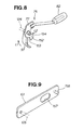
- Fig. 9 shows the meshing-engagement cancellation plate 101 of the second clutch-OFF switch mechanism.
- the meshing-engagement cancellation plate 101 interlocks with the first clutch-OFF switch mechanism 75 to cancel the meshing engagement between the ratchet 93 and the tooth portion 66 of the lock plate 65.
- the meshing-engagement cancellation plate 101 is connected at one end with the pin 105 of the emergency stop lever 83, and has a projecting pin 158 on another end portion.
- the projecting pin 158 abutting against the force receiving portion 154 of the first clutch-OFF switch mechanism 75 shown in Fig. 8 , the body 77 of the first clutch-OFF switch mechanism 75 is caused to pivot, so that the ratchet 93 is lifted up, by the claw-disengaging portion 97, out of the engagement with the lock plate 65.
- Elongated hole 157 is formed in a portion of the disengaging plate 101 adjacent to the other end of the plate 101, and the first pivot shaft 91 extends through the hole 157 in such a manner that the disengaging plate 101 may not interfere with the first shaft 91 when the emergency stop lever 83 is operated.
- the clutch lever 51 is further pulled by further pivoting movement of the second pivot member 94, as shown in Fig. 10B .
- the clutch cable 46 takes a maximum-pulled state (i.e., state in which the cable 46 has been pulled by a given stroke amount Lm), and the distance E between the cable 46 and the second pivot shaft 95 has now decreased. Therefore, force applied to the second pivot member 94, via the clutch cable 46, to return the pivot member 94 (in a direction opposite the arrow a3 direction) is reduced; thus, the force with which the human operator has to continue gripping the main clutch lever 51 can be reduced.
- the instant embodiment can effectively reduce the necessary gripping force (with which the human operator has to continue gripping the main clutch lever 51) while securing the stroke amount Lm of the clutch cable 46 and thus achieve enhanced operability of the main clutch lever 51.
- the main clutch lever 51 is returned to the clutch-OFF position Cf via the clutch lever spring 133 ( Fig. 4 ).
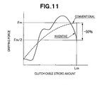
- Fig. 11 is a graph showing relationship between the gripping force to be applied to the main clutch lever 51 (i.e., with which the human operator has to continue gripping the main clutch lever 51) and the stroke amount of the clutch cable 46, where the horizontal axis represents the stroke amount and the vertical axis represents the gripping force (operating load).
- Broken line indicates a curve of an example of a conventionally-known machine provided with no operation mechanism constructed like the aforementioned operation mechanism 13, while a solid line indicates a curve of the instant embodiment provided with the aforementioned operation mechanism 13.
- Fm indicates the gripping force (operating load) in the conventionally-known machine; namely, with the conventionally- known machine, the human operator has to continue gripping the main clutch lever with the gripping force Fm.
- Fm/2 indicates the gripping force (operating load) in the instant embodiment; namely, with the instant embodiment, the human operator only has to continue gripping the main clutch lever 51 with about half (i.e., 50%) of the gripping force Fm in the conventionally-known machine.
- the instant embodiment can reduce the gripping force to be applied to the main clutch lever 51 while securing the stroke amount Lm of the cable member 46.
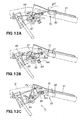
- Figs. 12A - 12C show behavior when the clutch is turned off in response to the human operator operating the first clutch-OFF switch mechanism 75, in which illustration of the side clutch lever 27 is omitted to facilitate understanding. The following paragraphs describe the behavior with combined reference to Figs. 12A - 12C and Fig. 4 .
- the claw-disengaging section 97 flips up the ratchet 93 in a direction of an arrow b2 against the biasing force of the claw spring 142.
- the second pivot member 94 starts reverse-pivoting (i.e., pivoting counterclockwise in the figure) as indicated by an arrow b4, and thus, the first pivot member 92 reverse-pivots (i.e., pivots counterclockwise in the figure) as indicated by an arrow b5.
- the ratchet 93 pivots, by the biasing force of the claw spring 142 ( Fig. 4 ), while pressing the claw-disengaging section 97 of the first clutch-OFF switch mechanism 75.
- the operation mechanism 13 in the instant embodiment includes the clutch-OFF mechanism 72 that, in response to the human operator operating the first clutch-OFF mechanism 75 disposed near the operating handle 12, places the clutch mechanism 42 in the OFF state by canceling the connection between the main clutch lever 51 and the second pivot member 94.
- the operation mechanism 13 can place the clutch mechanism 42 in the OFF state even while the main clutch lever 51 is being gripped, to thereby enhance the operability.
- the ratchet 93 pivots (in a direction of arrow b6) to engage with the tooth portion 66 of the lock plate 65 (see Fig. 3 ) and simultaneously presses the claw-disengaging section 97 of the first clutch-OFF switch mechanism 75, so that the operating section 82 returns to the initial position ( Fig. 3 ).
- Figs. 13A - 13C show a manner in which the second clutch-OFF switch mechanism 76 and the first clutch-OFF switch mechanism 75 interlock with each other in response to human operator's operation of the switch mechanism 76.
- the human operator pushes forward the emergency stop lever 83 of the second clutch-OFF switch mechanism 76, as indicated by the arrow c1 in Fig. 13A , while gripping the main clutch lever 51.
- the projecting pin 158 of the meshing-engagement disengaging plate 101 pushes forward the force receiving portion 154 of the first clutch-OFF switch mechanism 75 ( Fig. 8 ) as indicated by the arrow c2. Consequently, the claw-disengaging section 97 flips up the ratchet 93 as indicated by the arrow b2 against the biasing force of the claw spring 142 ( Fig. 4 ). In this way, the first clutch-OFF switch mechanism 75 interlocks with the second clutch-OFF switch mechanism 76 when the latter 76 has been operated by the human operator.
- the above-described embodiment can turn off the clutch mechanism 42 even while the main clutch lever 51 is being gripped by the human operator, and can thereby significantly enhance the operability.
- Operation mechanism of a working machine includes a main clutch lever (51) pivotably provided on an operating handle (12), and a pivot member (94) operable in interlocked relation to pivoting operation of the main clutch lever.
- the pivot member pivots about a second pivot point (95) differing in position from a first pivot point (91) of the main clutch lever.
- the cable member When fully pulled by pivoting operation of the main clutch lever, the cable member is located nearest to the second pivot point of the pivot member, so that force reverse-pivoting the pivot member is reduced.
Landscapes
- Engineering & Computer Science (AREA)
- Mechanical Engineering (AREA)
- Life Sciences & Earth Sciences (AREA)
- Chemical & Material Sciences (AREA)
- Soil Sciences (AREA)
- Environmental Sciences (AREA)
- General Engineering & Computer Science (AREA)
- Combustion & Propulsion (AREA)
- Transportation (AREA)
- Power Engineering (AREA)
- Arrangement And Mounting Of Devices That Control Transmission Of Motive Force (AREA)
- Mechanical Control Devices (AREA)
- Soil Working Implements (AREA)
Abstract
Description
- The present invention relates to an operation mechanism of a working machine which is provided on an operating handle and includes a clutch lever for remote-operating a clutch.
-
JP 2005-88769 A JP 2006-116977 A - The travel safe device disclosed in
JP 2005-88769 A - However, with the aforementioned travel safety device, there would arise the problem that, when the travel clutch is to be held in the ON state, the human operator has to move the release rod rearwardly by putting his or her finger on the release rod after gripping the deadman clutch lever together with the grip portion of the operating handle, which would undesirably increase the number of necessary operation steps, take a lot of trouble and lower the operability.
- With the travel clutch lever disclosed in
JP 2006-116977 A - However, when the main clutch lever is to be pivoted from the upper, OFF position to the lower, ON position, the aforementioned travel clutch lever would present the problem that the main clutch lever is hard to pivot downward because the resilient force of the toggle spring becomes resistance to the pivoting movement of the main clutch lever. Namely, because the resilient force of the toggle spring is added to the resilient force of an ordinary return spring used, the pivoting movement of the main clutch lever is subjected to greater resistance, which would thus lower the operability of the main clutch lever.
- In view of the foregoing prior art problems, it is an object of the present invention to provide an improved operation mechanism of a working machine which can achieve enhanced operability of a main clutch lever by allowing a human operator to continue gripping the main clutch lever with reduced force while securing a given stroke amount of a cable member.
- According to the present invention, there is provided an improved operation mechanism of a working machine, which comprises: a main clutch lever pivotably provided on an operating handle; a pivot member pivotable in response to pivoting operation of the main clutch lever; and a cable member for turning on a clutch mechanism in response to pivoting movement of the pivot member. The pivot member includes: a cable connection section having one end portion of the cable member connected thereto; and a pivot point disposed between a portion of the cable member located near the cable connection section and a pivot point of the main clutch lever.
- When the cable member has been fully pulled by pivoting movement of the pivot member operable in interlocked relation to pivoting operation of the main clutch lever, the cable member is located nearest to the pivot point of the pivot member, so that a distance between the cable member and the pivot member decreases; thus, force that reverse-pivots the pivot member can be reduced. As a result, the present invention can effectively reduce the gripping force (with which a human operator has to continue gripping the main clutch lever) while securing a given stroke amount of the cable member and thus achieve significantly-enhanced operability of the main clutch lever.
- Preferably, the operation mechanism further comprises a first clutch-OFF switch mechanism disposed near the operating handle, and a clutch-OFF mechanism for canceling the connection between the main clutch lever and the pivot member, in response to operation of the first clutch-OFF switch mechanism, to turn off the clutch mechanism. Thus, the clutch mechanism can be turned off even while the main clutch lever is being gripped by the human operator; as a result, the operability can be even further enhanced.
- Preferably, the clutch-OFF mechanism further includes a second clutch-OFF switch mechanism rotatably supported on the operating handle and disposed beneath the operating handle. When the second clutch-OFF switch mechanism is operated, the clutch-OFF mechanism transmits operating force from the second clutch-OFF switch mechanism to the first clutch-OFF switch mechanism to turn off the clutch mechanism. Thus, the present invention can turn off the clutch mechanism even while the main clutch lever is being gripped by the human operator, so that the operability can be even further enhanced.
- The following will describe embodiments of the present invention, but it should be appreciated that the present invention is not limited to the described embodiments and various modifications of the invention are possible without departing from the basic principles. The scope of the present invention is therefore to be determined solely by the appended claims.
- Certain preferred embodiments of the present invention will be described in detail below, by way of example only, with reference to the accompanying drawings, in which:
-
Fig. 1 is a side view of a working machine provided with an operation mechanism according to an embodiment of the present invention; -
Fig. 2 is a view showing in enlarged scale a "2" section shown inFig. 1 ; -
Fig. 3 is a view of the operation mechanism, which particularly shows in section a main clutch lever ofFig. 2 ; -
Fig. 4 is a top plan view of the operation mechanism, which particularly shows in section a support bracket ofFig. 2 ; -
Fig. 5 is a perspective view of the support bracket shown inFig. 2 ; -
Fig. 6 is a perspective view of the main clutch lever; -
Fig. 7 is a perspective view of a first pivot member shown inFig. 3 ; -
Fig. 8 is a perspective view of a first clutch-OFF switch mechanism shown inFig. 3 ; -
Fig. 9 is a perspective view of a meshing-engagement cancellation plate of a second clutch-OFF switch mechanism shown inFig. 3 ; -
Figs. 10A and 10B are partly-sectional views showing a manner in which the pivot member pulls a cable member in response to pivoting operation of the main clutch lever; -
Fig. 11 is a graph showing relationship between gripping force to be applied to the main clutch lever and stroke amount of the cable member; -
Figs. 12A - 12C are views showing behavior when the first clutch- OFF switch mechanism has been operated; and -
Figs. 13A- 13C are views showing behavior when a second clutch- OFF switch mechanism has been operated. - Referring first to
Fig. 1 , aworking machine 11 such as a tilling machine, to which is applied the present invention, includes anoperation mechanism 13 provided on anoperating handle 12, anengine 16 provided on anupper portion 15 of amachine body 14, atransmission case 21 provided on arear portion 17 of themachine body 14, a transmission mechanism (not shown) provided within thetransmission case 21, abelt transmission mechanism 22 for transmitting drive force from theengine 16 to the transmission mechanism,side clutches 23 provided in left and right lower end portions of thetransmission case 21, travelingwheels 25 driven by the drive force from theside clutches 24, aresistance rod 26 provided on a rear end portion of thetransmission case 21, and side clutch levers provided on left and right upper portions of theoperating handle 12. - The
operating handle 12 has a lower end portion attached to an upper end portion of thetransmission case 21.Fuel tank 32 andair cleaner 33 are attached to an upper portion of anengine body 31. -
Belt transmission mechanism 22 includes adriving pulley 36 mounted on anoutput shaft 35 of theengine 16, a drivenpulley 38 mounted on aninput shaft 37 of the transmission mechanism, and atransmission belt 41 wound at its opposite ends on thedriving pulley 36 and drivenpulley 38. Drive force from theoutput shaft 35 is transmitted to the transmission mechanism via theinput shaft 37. - As the
input shaft 37 rotates, the drive force of theinput shaft 37 is transmitted to thetraveling wheels 25 via the transmission mechanism andside clutches 24. - The
belt transmission mechanism 22 includes aclutch mechanism 42. Theclutch mechanism 42 includes a pivotable arm 43, atension roller 44 mounted on a distal end of the arm 43, a shock-absorbingspring 46 connected retained at its one end on a middle portion of the arm 43, and aclutch cable 46 connected to the other end of thespring 45. - The
clutch cable 46 has oneend portion 47 to theoperation mechanism 13. Theclutch mechanism 42 is operated by a human operator pulling theclutch cable 46 via a main clutch lever ("deadman clutch lever") 51. - The
belt mechanism 22 is shifted from an OFF state to an ON state by the human operator applying operating force Fh to themain clutch lever 51 to thereby pivot thelever 51 from a clutch-OFF position Cf to a clutch-ON position Cn. As a consequence, thetraveling wheels 25 are driven, via theside clutches 24, for soil-cultivating or tilling operation. - Once the human operator releases (i.e., releases his or her hand from) the
main clutch lever 51 to remove the operating force, theclutch lever 51 returns to the clutch OFF position Cf and theclutch mechanism 42 shifts from the ON state to the OFF state, so that thetraveling wheels 25 having so far been driven are stopped. - As seen from the foregoing, the
operation mechanism 13 performs a predetermined clutching operation by theclutch cable 46 being pulled in response to the human operator operating themain clutch lever 51 provided on the operating handle. "performing a clutching operation" means placing theclutch mechanism 42 in the ON state or OFF state, i.e. turns on or off theclutch mechanism 42. - As shown in
Fig. 2 , theoperation mechanism 13 includes a clutch-ON mechanism 71 for the operator to turn on the clutch by gripping themain clutch lever 51, a clutch-OFF mechanism 72 for the human operator to turn off the clutch while gripping themain clutch lever 51, and a compulsory clutch-OFF mechanism 73. - The clutch-
ON mechanism 71 turns on theclutch mechanism 42 ofFig. 1 in response to the human operator gripping themain clutch lever 51. The clutch-OFF mechanism 72 compulsorily turns off theclutch mechanism 42, via a first clutch-OFF switch mechanism 75, even while themain clutch lever 51 is being gripped by the human operator. - The compulsory clutch-
OFF mechanism 73 compulsorily activates the clutch-OFF mechanism 72, via a second clutch-OFF switch mechanism 76, even while themain clutch lever 51 is being gripped by the human operator. - Left and
right support brackets 81 are fixed to theoperating handle 12, and one of the support brackets (e.g., left support bracket) 81 pivotably supports themain clutch lever 51, anoperating section 82 of the first clutch-OFF switch mechanism 75 and anemergency stop lever 83 of the second clutch-OFF switch mechanism 76. -
Figs. 3 and4 show theoperation mechanism 13 with part of the support bracket (e.g., left support bracket) 81 taken away. Thesupport bracket 81 is fixed by welding to a front portion of aleft grip 85 of theoperating handle 12. Themain clutch lever 51 and first pivot member (deadman plate) 92 are pivotably supported on thesupport bracket 81 via a first pivot shaft (i.e., first pivot point) 91, and aratchet 93 is pivotably attached to thefirst pivot member 92. - L-shaped, second pivot member (plate lever) 94 is pivotably attached to the
support bracket 81 via a second pivot shaft (second pivot point) 95. Theclutch cable 46 is connected at oneend portion 47 to thesecond pivot member 94. Reference character Ps represents an initial position of thesecond pivot member 94. - The first clutch-
OFF switch mechanism 75 includes the operatingsection 82, and a claw-disengagingsection 97 for canceling an engaging state of theratchet 93 in response to input from the operatingsection 82. - The second clutch-
OFF switch mechanism 76 includes theemergency stop lever 83 pivotably attached to thesupport bracket 81, and a meshing-engagement cancellation plate (link plate) 101 connected to theemergency stop lever 83. - The
emergency stop lever 83 includes afirst bar 103 extending between the left and right support brackets 81 (only theleft support bracket 81 is shown in the figures), and left and right second bars 104 (only one of which is shown in the figures) fitted in the left andright support brackets 81. The leftsecond bar 104 has apin 105, and the above-mentioned meshing-engagement cancellation plate 101 is connected to thepin 105. - As shown in
Figs. 2 ,3 and5 , each of thesupport bracket 81, which has a generally "U" sectional shape, has a firstside wall portion 107, a secondside wall portion 112 and a bottom portion 111 connecting between the first and secondside wall portions First edge portion 106 defining the upper edge of the firstside wall portion 107 of thesupport bracket 81 is fixed by welding to theoperating handle 12. The secondside wall portion 112 has aportion 112a bent toward the firstside wall portion 107.Second edge portion 113 defining the inner edge of thebent portion 112a is fixed by welding to theoperating handle 12. Thesecond wall portion 112 has, on itsfront edge 112a, abracket 114 of a U sectional shape for pivotably supporting theemergency stop lever 83 shown inFig. 2 . -
Third edge portion 115 defining the upper end of thebracket 114 is fixed by welding to theoperating handle 12. Lower end portion of thebracket 114 is formed asstopper portions 116 flaring obliquely downward away from each other. Thestopper portions 116 are formed so as to limit pivoting movement of thesecond bar 104. Opening 117 for insertion therein of thepin 105 of thesecond bar 104 is formed in a lower end portion of thebracket 114.Boss hole 118 for rotatably support theemergency stop lever 83 of the second clutch-OFF switch mechanism 76 is formed centrally in thebracket 114. - The first and
second wall portions first pivot shaft 91, and second boss holes 122 formed for insertion therethrough of thesecond pivot shaft 95. - The
second wall portion 112 has anopening 123 formed to avoid interference with the first pivot member 92 (Fig 3 ), and athird pivot shaft 124 mounted thereto for supporting the first clutch-OFF switch mechanism 75 (Fig. 3 ). - The
first wall portion 107 has astopper projection 125 formed on its front edge for holding the main clutch lever 51 (Fig. 3 ) in the OFF position Cf. As shown inFigs. 2 ,3 ,4 and6 , the mainclutch lever 51, which has a generally U sectional shape, first and second supportingleg portions Fig. 2 ) formed in the first and second supportingleg portions first pivot shaft 91, alock plate 65 mounted on thefirst pivot shaft 91, agrip portion 132 extending rearward from the first and second supportingleg portions Fig. 4 ) retained on the first supportingleg portion 126. The mainclutch lever 51 is pivotable about thefirst pivot shaft 91. Thus, thefirst pivot shaft 91 functions as the first pivot point of the mainclutch lever 51. Theclutch lever spring 133 normally biases the mainclutch lever 51 to the clutch-OFF position Cf. Theratchet 93 shown inFig. 3 disengageably engages with atooth portion 66 of thelock plate 65. -
Fig. 7 shows details of thefirst pivot member 92 shown inFig. 3 . As shown inFigs. 3 ,4 and7 , thefirst pivot member 92 has acentral hole 137 for insertion therethrough of thefirst pivot shaft 91, acam portion 138 formed on one end portion thereof, asupport pin 141 provided on another end portion thereof, and aclaw spring 142 wound on thesupport pin 141 and having one end portion engaging with theratchet 93. As shown inFigs. 3 and4 , thesecond pivot member 94 includes an L-shapedbody 145 having first andsecond leg portions Roller 144 rotatably supported on thefirst leg portion 94a moves along the lower surface of thecam portion 138 of thefirst pivot member 92. Thesecond leg portion 94b has acable connection portion 146 for connecting thereto the oneend portion 47 of theclutch cable 46. Thesecond pivot member 94 pivots about thesecond pivot shaft 95; thus, thesecond pivot shaft 95 functions as a second pivot point. - As set forth above, the
second pivot member 94 has thesecond pivot point 95 differing in position from thefirst pivot point 91 of the mainclutch lever 51. Namely, as viewed from a side of the working machine 11 (Fig. 1 ), thesecond pivot point 95 of thesecond pivot member 94 is disposed between a portion of theclutch cable 46 located near the cable connection section 146 (i.e., a portion of thecable 46 located in a range of a distance B from the oneend portion 47 to acoated end portion 148 of the clutch cable 46) and the first pivot point 191 of the mainclutch lever 51; that is, thesecond pivot point 95 is located in a range of a distance E as viewed from a side of the workingmachine 11, as shown inFig. 2 . - The
first pivot member 92 is pivotably supported on thefirst pivot shaft 91 that rotatably supports thereon the mainclutch lever 51. Namely, the pivot point of thefirst pivot member 92 is identical to thefirst pivot point 91 of the mainclutch lever 51. - Therefore, when the main
clutch lever 51 is operated to pivot, thefirst pivot member 92 causes thesecond pivot member 94 to pivot, via thecam portion 138 androller 144, until theclutch cable 46 reaches near the second pivot shaft (second pivot point) 95. - The
ratchet 93 is pivotably supported on thesupport pin 141 of thefirst pivot member 92 shown inFig. 3 . Thisratchet 93 is normally biased by theclaw spring 142 in a direction where it is held in engagement with thetooth portion 66 of thelock plate 65. - As the human operator operates downwardly the
operating section 82 of the first clutch-OFF switch mechanism 75, theratchet 93 is flipped up, against the biasing force of theclaw spring 142, out of the engagement with thetooth portion 66 of thelock plate 65. -
Fig. 8 shows details of the first clutch-OFF switch mechanism 75. As shown inFigs. 3 ,4 and8 , the first clutch-OFF switch mechanism 75 includes the operatingsection 82 fixed to one end portion of abody 77 and operable with a hand of the human operator, and a switchpivot point hole 152 formed centrally in thebody 77 such that thethird pivot shaft 124, pivotably supporting thebody 77, is fitted in thehole 152. The first clutch-OFF switch mechanism 75 also includes the claw-disengagingsection 97 formed at another end portion of thebody 77 such that, as it pivots in a direction of an arrow c1, it abuts against the ratchet 93 (Fig. 3 ) to disengage theratchet 93, a recessedportion 153 for avoiding interference with the first pivot shaft 91 (Fig. 3 ), and aforce receiving portion 154 for receiving force from the second clutch-OFF switch mechanism 76 (Fig. 3 ), as indicated by an arrow c2, to cause thebody 77 to pivot. - The claw-disengaging
section 97 also functions as a guide for thedisengaged ratchet 93, so as to avoid interference with the mainclutch lever 51. -
Fig. 9 shows the meshing-engagement cancellation plate 101 of the second clutch-OFF switch mechanism. As theemergency stop lever 83 is operated, the meshing-engagement cancellation plate 101 interlocks with the first clutch-OFF switch mechanism 75 to cancel the meshing engagement between theratchet 93 and thetooth portion 66 of thelock plate 65. - Referring now to
Figs. 3 ,4 and9 , the meshing-engagement cancellation plate 101 is connected at one end with thepin 105 of theemergency stop lever 83, and has a projectingpin 158 on another end portion. By the projectingpin 158 abutting against theforce receiving portion 154 of the first clutch-OFF switch mechanism 75 shown inFig. 8 , thebody 77 of the first clutch-OFF switch mechanism 75 is caused to pivot, so that theratchet 93 is lifted up, by the claw-disengagingportion 97, out of the engagement with thelock plate 65. -
Elongated hole 157 is formed in a portion of the disengagingplate 101 adjacent to the other end of theplate 101, and thefirst pivot shaft 91 extends through thehole 157 in such a manner that the disengagingplate 101 may not interfere with thefirst shaft 91 when theemergency stop lever 83 is operated. - Next, behavior of the main
clutch lever 51 andsecond pivot member 94 will be described with primary reference toFigs. 3 ,10A and 10B . - First, once the human operator starts gripping the main
clutch lever 51, as indicated by an arrow a1, when thelever 51 is in the clutch-OFF position Cf, thefirst pivot member 92 starts rotating in a direction of an arrow a2 by means of theratchet 93 meshing with thetooth portion 66 of thelock plate 65. - As the
first pivot member 92 rotates in the direction of the arrow a2, theroller 144 starts rolling and thesecond pivot member 94 pivots about thesecond pivot shaft 95, in a direction of an arrow a3, to start pulling theclutch cable 46 as indicated by an arrow a4, as shown inFig. 10A ,. - As the human operator continues the pivoting operation of the main
clutch lever 51, theclutch lever 51 is further pulled by further pivoting movement of thesecond pivot member 94, as shown inFig. 10B . - Once the main
clutch lever 51 reaches the clutch-ON position Cn in response to the human operator pivoting the mainclutch lever 51 to a fully-pivoted position, theclutch cable 46 takes a maximum-pulled state (i.e., state in which thecable 46 has been pulled by a given stroke amount Lm), and the distance E between thecable 46 and thesecond pivot shaft 95 has now decreased. Therefore, force applied to thesecond pivot member 94, via theclutch cable 46, to return the pivot member 94 (in a direction opposite the arrow a3 direction) is reduced; thus, the force with which the human operator has to continue gripping the mainclutch lever 51 can be reduced. - As a consequence, the instant embodiment can effectively reduce the necessary gripping force (with which the human operator has to continue gripping the main clutch lever 51) while securing the stroke amount Lm of the
clutch cable 46 and thus achieve enhanced operability of the mainclutch lever 51. - Once the human operator releases the main
clutch lever 51, the mainclutch lever 51 is returned to the clutch-OFF position Cf via the clutch lever spring 133 (Fig. 4 ). -
Fig. 11 is a graph showing relationship between the gripping force to be applied to the main clutch lever 51 (i.e., with which the human operator has to continue gripping the main clutch lever 51) and the stroke amount of theclutch cable 46, where the horizontal axis represents the stroke amount and the vertical axis represents the gripping force (operating load). Broken line indicates a curve of an example of a conventionally-known machine provided with no operation mechanism constructed like theaforementioned operation mechanism 13, while a solid line indicates a curve of the instant embodiment provided with theaforementioned operation mechanism 13. - Further, in
Fig. 11 , Fm indicates the gripping force (operating load) in the conventionally-known machine; namely, with the conventionally- known machine, the human operator has to continue gripping the main clutch lever with the gripping force Fm. Fm/2 indicates the gripping force (operating load) in the instant embodiment; namely, with the instant embodiment, the human operator only has to continue gripping the mainclutch lever 51 with about half (i.e., 50%) of the gripping force Fm in the conventionally-known machine. Thus, the instant embodiment can reduce the gripping force to be applied to the mainclutch lever 51 while securing the stroke amount Lm of thecable member 46. -
Figs. 12A - 12C show behavior when the clutch is turned off in response to the human operator operating the first clutch-OFF switch mechanism 75, in which illustration of the sideclutch lever 27 is omitted to facilitate understanding. The following paragraphs describe the behavior with combined reference toFigs. 12A - 12C andFig. 4 . - Once the human operator depresses the operating
section 82 of the first clutch-OFF switch mechanism 75, as indicated by an arrow b1 inFig. 12A , while gripping the mainclutch lever 51, the claw-disengagingsection 97 flips up theratchet 93 in a direction of an arrow b2 against the biasing force of theclaw spring 142. - Referring to
Fig. 12B , once theratchet 93 is flipped up, thesecond pivot member 94 starts reverse-pivoting (i.e., pivoting counterclockwise in the figure) as indicated by an arrow b4, and thus, thefirst pivot member 92 reverse-pivots (i.e., pivots counterclockwise in the figure) as indicated by an arrow b5. At that time, theratchet 93 pivots, by the biasing force of the claw spring 142 (Fig. 4 ), while pressing the claw-disengagingsection 97 of the first clutch-OFF switch mechanism 75. - As shown in
Fig. 12C , the clutch mechanism 42 (Fig. 1 ) is brought back to the OFF state once thesecond member 94 returns to the initial position Ps. - As set forth above, the
operation mechanism 13 in the instant embodiment includes the clutch-OFF mechanism 72 that, in response to the human operator operating the first clutch-OFF mechanism 75 disposed near the operatinghandle 12, places theclutch mechanism 42 in the OFF state by canceling the connection between the mainclutch lever 51 and thesecond pivot member 94. With such a clutch-OFF mechanism 72, theoperation mechanism 13 can place theclutch mechanism 42 in the OFF state even while the mainclutch lever 51 is being gripped, to thereby enhance the operability. - Once the human operator releases the
operating section 82 of the mainclutch lever 51 and releases the mainclutch lever 51, the mainclutch lever 51 is returned to the clutch-OFF position Cf via theclutch lever spring 133. - Once the main
clutch lever 51 returns to the clutch-OFF position Cf, theratchet 93 pivots (in a direction of arrow b6) to engage with thetooth portion 66 of the lock plate 65 (seeFig. 3 ) and simultaneously presses the claw-disengagingsection 97 of the first clutch-OFF switch mechanism 75, so that the operatingsection 82 returns to the initial position (Fig. 3 ). -
Figs. 13A - 13C show a manner in which the second clutch-OFF switch mechanism 76 and the first clutch-OFF switch mechanism 75 interlock with each other in response to human operator's operation of theswitch mechanism 76. - Namely, the human operator pushes forward the
emergency stop lever 83 of the second clutch-OFF switch mechanism 76, as indicated by the arrow c1 inFig. 13A , while gripping the mainclutch lever 51. - Once the
emergency stop lever 83 is pushed forward as noted above, the projectingpin 158 of the meshing-engagement disengaging plate 101 pushes forward theforce receiving portion 154 of the first clutch-OFF switch mechanism 75 (Fig. 8 ) as indicated by the arrow c2. Consequently, the claw-disengagingsection 97 flips up theratchet 93 as indicated by the arrow b2 against the biasing force of the claw spring 142 (Fig. 4 ). In this way, the first clutch-OFF switch mechanism 75 interlocks with the second clutch-OFF switch mechanism 76 when the latter 76 has been operated by the human operator. - Once the
ratchet 93 is flipped up as shown inFig. 13C , the clutch mechanism 42 (Fig. 1 ) is brought to the OFF state in the same manner as inFig. 12C . - Namely, once the second clutch-
OFF switch mechanism 76 is operated by the human operator, the operating force is transmitted from the second clutch-OFF switch mechanism 76 to the first clutch-OFF switch mechanism 75, so that the clutch-OFF mechanism 72 is automatically operated. As a result, the above-described embodiment can turn off theclutch mechanism 42 even while the mainclutch lever 51 is being gripped by the human operator, and can thereby significantly enhance the operability. - Whereas the operation mechanism of the working machine of the present invention has been described above as applied to a tilling machine, it may be applied to other machines than tilling machines.
- Operation mechanism of a working machine includes a main clutch lever (51) pivotably provided on an operating handle (12), and a pivot member (94) operable in interlocked relation to pivoting operation of the main clutch lever. The pivot member pivots about a second pivot point (95) differing in position from a first pivot point (91) of the main clutch lever. When fully pulled by pivoting operation of the main clutch lever, the cable member is located nearest to the second pivot point of the pivot member, so that force reverse-pivoting the pivot member is reduced.
Claims (3)
- An operation mechanism of a working machine comprising:a main clutch lever (51) pivotably provided on an operating handle (12);a pivot member (94) pivotable in response to pivoting operation of said main clutch lever; anda cable member (46) for turning on a clutch mechanism (42) in response to pivoting movement of said pivot member,said pivot member (94) including:a cable connection section (146) having one end portion of said cable member connected thereto; anda pivot point (95) disposed between a portion of said cable member located near said cable connection section and a pivot point (91) of said main clutch lever.
- The operation mechanism of claim 1, which further comprises a first clutch-OFF switch mechanism (75) disposed near the operating handle, and a clutch-OFF mechanism (72) for canceling connection between said main clutch lever and said pivot member, in response to operation of said first clutch-OFF switch mechanism, to turn off the clutch mechanism.
- The operation mechanism of claim 2, wherein said clutch-OFF mechanism (72) further includes a second clutch-OFF switch mechanism (76) rotatably supported on the operating handle and disposed beneath the operating handle, and, when said second clutch-OFF switch mechanism is operated, said clutch-OFF mechanism transmits operating force from said second clutch-OFF switch mechanism to said first clutch-OFF switch mechanism (75) to turn off the clutch mechanism (42).
Applications Claiming Priority (1)
| Application Number | Priority Date | Filing Date | Title |
|---|---|---|---|
| JP2006321970A JP4680873B2 (en) | 2006-11-29 | 2006-11-29 | Working machine operation mechanism |
Publications (2)
| Publication Number | Publication Date |
|---|---|
| EP1927536A1 true EP1927536A1 (en) | 2008-06-04 |
| EP1927536B1 EP1927536B1 (en) | 2010-08-04 |
Family
ID=39047564
Family Applications (1)
| Application Number | Title | Priority Date | Filing Date |
|---|---|---|---|
| EP07022696A Not-in-force EP1927536B1 (en) | 2006-11-29 | 2007-11-22 | Operation mechanism of working machine |
Country Status (5)
| Country | Link |
|---|---|
| US (1) | US7905339B2 (en) |
| EP (1) | EP1927536B1 (en) |
| JP (1) | JP4680873B2 (en) |
| CN (1) | CN100594142C (en) |
| DE (1) | DE602007008189D1 (en) |
Cited By (3)
| Publication number | Priority date | Publication date | Assignee | Title |
|---|---|---|---|---|
| ITMO20080289A1 (en) * | 2008-11-12 | 2010-05-13 | Valpadana S P A | SELF PROPELLED MACHINE WITH ACCIDENT PREVENTION. |
| CN103899674A (en) * | 2014-03-11 | 2014-07-02 | 李斯端 | Control mechanism of clutch handle |
| WO2022175931A1 (en) * | 2021-05-27 | 2022-08-25 | Potignano Antonio | Safety clutch for operating machines and method therefor |
Families Citing this family (7)
| Publication number | Priority date | Publication date | Assignee | Title |
|---|---|---|---|---|
| JP5011270B2 (en) * | 2008-12-22 | 2012-08-29 | 本田技研工業株式会社 | Clutch operating device |
| CN101660657B (en) * | 2009-09-15 | 2012-05-23 | 陈恳 | Secure automatic emergency stop device for hand-held working machine |
| CN102007834B (en) * | 2010-10-15 | 2012-05-23 | 陈恳 | Micro-cultivator anti-misoperation device |
| US9206863B2 (en) * | 2013-01-09 | 2015-12-08 | Mark Patterson | Clutch engagement mechanism |
| US11827294B2 (en) | 2019-06-07 | 2023-11-28 | Briggs & Stratton, Llc | Single handed walk behind mower controls |
| US12365366B1 (en) * | 2021-06-14 | 2025-07-22 | Scythe Robotics, Inc. | Control interfaces for autonomous lawn mowers |
| IT202200004544A1 (en) * | 2022-03-09 | 2023-09-09 | Antonio Potignano | HYDRAULIC CLUTCH FOR OPERATING MACHINES |
Citations (6)
| Publication number | Priority date | Publication date | Assignee | Title |
|---|---|---|---|---|
| FR2623765A1 (en) | 1987-11-30 | 1989-06-02 | Kubota Ltd | |
| JPH06312628A (en) | 1993-04-30 | 1994-11-08 | Kubota Corp | Clutch operating structure for walking type mobile agricultural machinery |
| JPH06320977A (en) | 1993-05-10 | 1994-11-22 | Kubota Corp | Main clutch operating structure for walk-behind mobile agricultural machine |
| JPH0948257A (en) | 1995-08-07 | 1997-02-18 | Yanmar Agricult Equip Co Ltd | Farm work machine |
| JP2003011691A (en) * | 2001-07-03 | 2003-01-15 | Mitsubishi Agricult Mach Co Ltd | Emergency stop lever device for farm working machine |
| JP2003072412A (en) * | 2001-08-31 | 2003-03-12 | Mitsubishi Agricult Mach Co Ltd | Walking type working vehicle |
Family Cites Families (7)
| Publication number | Priority date | Publication date | Assignee | Title |
|---|---|---|---|---|
| JPH04113224U (en) * | 1991-01-18 | 1992-10-02 | ヤンマー農機株式会社 | Management machine finger clutch |
| JPH04307120A (en) * | 1991-04-02 | 1992-10-29 | Kubota Corp | Operation structure of walking work vehicle |
| JPH079877A (en) * | 1993-06-28 | 1995-01-13 | Kubota Corp | Main clutch operating structure of walk-behind work machine |
| JPH11170885A (en) * | 1997-12-12 | 1999-06-29 | Kubota Corp | Clutch operating device for walking type working machine |
| JP4457341B2 (en) | 2003-09-18 | 2010-04-28 | 株式会社アテックス | Travel safety device for walking type work vehicle |
| JP2006116977A (en) | 2004-10-19 | 2006-05-11 | Atex Co Ltd | Traveling clutch lever |
| JP4528174B2 (en) * | 2005-03-18 | 2010-08-18 | 本田技研工業株式会社 | Walking type work machine |
-
2006
- 2006-11-29 JP JP2006321970A patent/JP4680873B2/en not_active Expired - Fee Related
-
2007
- 2007-11-22 DE DE602007008189T patent/DE602007008189D1/en active Active
- 2007-11-22 EP EP07022696A patent/EP1927536B1/en not_active Not-in-force
- 2007-11-28 CN CN200710196029A patent/CN100594142C/en not_active Expired - Fee Related
- 2007-11-28 US US11/987,171 patent/US7905339B2/en active Active
Patent Citations (6)
| Publication number | Priority date | Publication date | Assignee | Title |
|---|---|---|---|---|
| FR2623765A1 (en) | 1987-11-30 | 1989-06-02 | Kubota Ltd | |
| JPH06312628A (en) | 1993-04-30 | 1994-11-08 | Kubota Corp | Clutch operating structure for walking type mobile agricultural machinery |
| JPH06320977A (en) | 1993-05-10 | 1994-11-22 | Kubota Corp | Main clutch operating structure for walk-behind mobile agricultural machine |
| JPH0948257A (en) | 1995-08-07 | 1997-02-18 | Yanmar Agricult Equip Co Ltd | Farm work machine |
| JP2003011691A (en) * | 2001-07-03 | 2003-01-15 | Mitsubishi Agricult Mach Co Ltd | Emergency stop lever device for farm working machine |
| JP2003072412A (en) * | 2001-08-31 | 2003-03-12 | Mitsubishi Agricult Mach Co Ltd | Walking type working vehicle |
Cited By (4)
| Publication number | Priority date | Publication date | Assignee | Title |
|---|---|---|---|---|
| ITMO20080289A1 (en) * | 2008-11-12 | 2010-05-13 | Valpadana S P A | SELF PROPELLED MACHINE WITH ACCIDENT PREVENTION. |
| CN103899674A (en) * | 2014-03-11 | 2014-07-02 | 李斯端 | Control mechanism of clutch handle |
| WO2022175931A1 (en) * | 2021-05-27 | 2022-08-25 | Potignano Antonio | Safety clutch for operating machines and method therefor |
| IT202100013937A1 (en) * | 2021-05-27 | 2022-11-27 | Antonio Potignano | CLUTCH ACCIDENT PREVENTION FOR OPERATING MACHINES AND METHOD FOR THE SAME |
Also Published As
| Publication number | Publication date |
|---|---|
| US20080121491A1 (en) | 2008-05-29 |
| CN101190657A (en) | 2008-06-04 |
| DE602007008189D1 (en) | 2010-09-16 |
| US7905339B2 (en) | 2011-03-15 |
| CN100594142C (en) | 2010-03-17 |
| JP2008132930A (en) | 2008-06-12 |
| JP4680873B2 (en) | 2011-05-11 |
| EP1927536B1 (en) | 2010-08-04 |
Similar Documents
| Publication | Publication Date | Title |
|---|---|---|
| EP1927536B1 (en) | Operation mechanism of working machine | |
| CN104797185B (en) | sticky roller cleaning tool | |
| US4281732A (en) | Two-stage deadman control for walk-behind mower | |
| US4509614A (en) | Working vehicle equipped with engine automatic stop device | |
| US20100237516A1 (en) | Carburetor assembly | |
| JP2012035655A (en) | Seat slide apparatus for vehicle | |
| JP6698469B2 (en) | Forward/backward switching operation device for agricultural work machines | |
| JP4161200B2 (en) | Paper feeder | |
| JP5189937B2 (en) | Parking brake device | |
| JP3725379B2 (en) | Reach-type forklift battery drawer | |
| JP5466540B2 (en) | Management machine | |
| JP3384832B2 (en) | Double bearing reel | |
| JP5876369B2 (en) | Parking brake | |
| GB2287304A (en) | Control systems for land-drive lawnmowers | |
| JP6698470B2 (en) | Forward/backward switching operation device for agricultural work machines | |
| JP6449467B2 (en) | Vehicle seat lock device | |
| JP2001039185A (en) | Riding work machine | |
| KR101578072B1 (en) | Headrest Moving Device | |
| JP5087809B2 (en) | Seat lock device | |
| US8020469B2 (en) | Base frame and parking brake device | |
| CN100594143C (en) | Control rod for working machine | |
| JP4486011B2 (en) | Parking brake device | |
| JPS6310B2 (en) | ||
| JP2003048630A (en) | Paper feeder and image forming apparatus | |
| JPS5836599Y2 (en) | steering control device |
Legal Events
| Date | Code | Title | Description |
|---|---|---|---|
| PUAI | Public reference made under article 153(3) epc to a published international application that has entered the european phase |
Free format text: ORIGINAL CODE: 0009012 |
|
| 17P | Request for examination filed |
Effective date: 20071122 |
|
| AK | Designated contracting states |
Kind code of ref document: A1 Designated state(s): AT BE BG CH CY CZ DE DK EE ES FI FR GB GR HU IE IS IT LI LT LU LV MC MT NL PL PT RO SE SI SK TR |
|
| AX | Request for extension of the european patent |
Extension state: AL BA HR MK RS |
|
| AKX | Designation fees paid |
Designated state(s): DE FR GB |
|
| GRAP | Despatch of communication of intention to grant a patent |
Free format text: ORIGINAL CODE: EPIDOSNIGR1 |
|
| GRAS | Grant fee paid |
Free format text: ORIGINAL CODE: EPIDOSNIGR3 |
|
| RIN1 | Information on inventor provided before grant (corrected) |
Inventor name: ITO, TOMOKI Inventor name: MIYAHARA, KAZUYOSHI Inventor name: YAMAZAKI, NOBUO |
|
| GRAA | (expected) grant |
Free format text: ORIGINAL CODE: 0009210 |
|
| RAP1 | Party data changed (applicant data changed or rights of an application transferred) |
Owner name: HONDA MOTOR CO., LTD. |
|
| RIN1 | Information on inventor provided before grant (corrected) |
Inventor name: MIYAHARA, KAZUYOSHIC/O HONDA R&D CO., LTD. Inventor name: YAMAZAKI, NOBUOC/O HONDA R&D CO., LTD. Inventor name: ITO, TOMOKIC/O HONDA R&D CO., LTD. |
|
| AK | Designated contracting states |
Kind code of ref document: B1 Designated state(s): DE FR GB |
|
| REG | Reference to a national code |
Ref country code: GB Ref legal event code: FG4D |
|
| REF | Corresponds to: |
Ref document number: 602007008189 Country of ref document: DE Date of ref document: 20100916 Kind code of ref document: P |
|
| PLBE | No opposition filed within time limit |
Free format text: ORIGINAL CODE: 0009261 |
|
| STAA | Information on the status of an ep patent application or granted ep patent |
Free format text: STATUS: NO OPPOSITION FILED WITHIN TIME LIMIT |
|
| 26N | No opposition filed |
Effective date: 20110506 |
|
| REG | Reference to a national code |
Ref country code: DE Ref legal event code: R097 Ref document number: 602007008189 Country of ref document: DE Effective date: 20110506 |
|
| REG | Reference to a national code |
Ref country code: FR Ref legal event code: PLFP Year of fee payment: 9 |
|
| REG | Reference to a national code |
Ref country code: FR Ref legal event code: PLFP Year of fee payment: 10 |
|
| REG | Reference to a national code |
Ref country code: FR Ref legal event code: PLFP Year of fee payment: 11 |
|
| REG | Reference to a national code |
Ref country code: FR Ref legal event code: PLFP Year of fee payment: 12 |
|
| REG | Reference to a national code |
Ref country code: DE Ref legal event code: R084 Ref document number: 602007008189 Country of ref document: DE |
|
| REG | Reference to a national code |
Ref country code: GB Ref legal event code: 746 Effective date: 20191218 |
|
| PGFP | Annual fee paid to national office [announced via postgrant information from national office to epo] |
Ref country code: DE Payment date: 20191112 Year of fee payment: 13 |
|
| PGFP | Annual fee paid to national office [announced via postgrant information from national office to epo] |
Ref country code: FR Payment date: 20191014 Year of fee payment: 13 |
|
| PGFP | Annual fee paid to national office [announced via postgrant information from national office to epo] |
Ref country code: GB Payment date: 20191122 Year of fee payment: 13 |
|
| REG | Reference to a national code |
Ref country code: DE Ref legal event code: R119 Ref document number: 602007008189 Country of ref document: DE |
|
| GBPC | Gb: european patent ceased through non-payment of renewal fee |
Effective date: 20201122 |
|
| PG25 | Lapsed in a contracting state [announced via postgrant information from national office to epo] |
Ref country code: FR Free format text: LAPSE BECAUSE OF NON-PAYMENT OF DUE FEES Effective date: 20201130 |
|
| PG25 | Lapsed in a contracting state [announced via postgrant information from national office to epo] |
Ref country code: DE Free format text: LAPSE BECAUSE OF NON-PAYMENT OF DUE FEES Effective date: 20210601 Ref country code: GB Free format text: LAPSE BECAUSE OF NON-PAYMENT OF DUE FEES Effective date: 20201122 |