EP1926864B1 - Linking system for producing a link between building elements - Google Patents
Linking system for producing a link between building elements Download PDFInfo
- Publication number
- EP1926864B1 EP1926864B1 EP05850766A EP05850766A EP1926864B1 EP 1926864 B1 EP1926864 B1 EP 1926864B1 EP 05850766 A EP05850766 A EP 05850766A EP 05850766 A EP05850766 A EP 05850766A EP 1926864 B1 EP1926864 B1 EP 1926864B1
- Authority
- EP
- European Patent Office
- Prior art keywords
- dowel
- axis
- internal orifice
- hole
- building element
- Prior art date
- Legal status (The legal status is an assumption and is not a legal conclusion. Google has not performed a legal analysis and makes no representation as to the accuracy of the status listed.)
- Not-in-force
Links
- 238000010276 construction Methods 0.000 claims description 14
- 229910000831 Steel Inorganic materials 0.000 claims description 8
- 239000010959 steel Substances 0.000 claims description 8
- 239000002023 wood Substances 0.000 claims description 7
- BPQQTUXANYXVAA-UHFFFAOYSA-N Orthosilicate Chemical compound [O-][Si]([O-])([O-])[O-] BPQQTUXANYXVAA-UHFFFAOYSA-N 0.000 claims description 6
- 239000004033 plastic Substances 0.000 claims description 6
- 229920003023 plastic Polymers 0.000 claims description 6
- -1 polyethylene Polymers 0.000 claims description 6
- 239000004698 Polyethylene Substances 0.000 claims description 5
- 229920000573 polyethylene Polymers 0.000 claims description 5
- 239000002184 metal Substances 0.000 claims description 4
- 239000002245 particle Substances 0.000 claims description 4
- 239000002969 artificial stone Substances 0.000 abstract description 2
- 239000011449 brick Substances 0.000 description 16
- 239000004570 mortar (masonry) Substances 0.000 description 13
- 239000000463 material Substances 0.000 description 9
- 238000012545 processing Methods 0.000 description 5
- 150000001875 compounds Chemical class 0.000 description 4
- 241001295925 Gegenes Species 0.000 description 3
- 239000000853 adhesive Substances 0.000 description 3
- 230000001070 adhesive effect Effects 0.000 description 3
- 238000004519 manufacturing process Methods 0.000 description 3
- 238000000034 method Methods 0.000 description 3
- 241000283707 Capra Species 0.000 description 2
- 239000011083 cement mortar Substances 0.000 description 2
- 238000005524 ceramic coating Methods 0.000 description 2
- 239000002131 composite material Substances 0.000 description 2
- 239000004567 concrete Substances 0.000 description 2
- 230000001066 destructive effect Effects 0.000 description 2
- 230000007613 environmental effect Effects 0.000 description 2
- 238000003780 insertion Methods 0.000 description 2
- 230000037431 insertion Effects 0.000 description 2
- 230000007704 transition Effects 0.000 description 2
- 238000013459 approach Methods 0.000 description 1
- 238000005452 bending Methods 0.000 description 1
- 239000004566 building material Substances 0.000 description 1
- 230000001934 delay Effects 0.000 description 1
- 238000005553 drilling Methods 0.000 description 1
- 238000005516 engineering process Methods 0.000 description 1
- 210000003746 feather Anatomy 0.000 description 1
- 238000003801 milling Methods 0.000 description 1
- 238000012986 modification Methods 0.000 description 1
- 230000004048 modification Effects 0.000 description 1
- ORMNNUPLFAPCFD-DVLYDCSHSA-M phenethicillin potassium Chemical compound [K+].N([C@@H]1C(N2[C@H](C(C)(C)S[C@@H]21)C([O-])=O)=O)C(=O)C(C)OC1=CC=CC=C1 ORMNNUPLFAPCFD-DVLYDCSHSA-M 0.000 description 1
- 229920000642 polymer Polymers 0.000 description 1
- 238000002360 preparation method Methods 0.000 description 1
- 230000002787 reinforcement Effects 0.000 description 1
- 230000035939 shock Effects 0.000 description 1
- 239000007787 solid Substances 0.000 description 1
- 239000004575 stone Substances 0.000 description 1
- XLYOFNOQVPJJNP-UHFFFAOYSA-N water Substances O XLYOFNOQVPJJNP-UHFFFAOYSA-N 0.000 description 1
Images


Classifications
-
- E—FIXED CONSTRUCTIONS
- E04—BUILDING
- E04B—GENERAL BUILDING CONSTRUCTIONS; WALLS, e.g. PARTITIONS; ROOFS; FLOORS; CEILINGS; INSULATION OR OTHER PROTECTION OF BUILDINGS
- E04B2/00—Walls, e.g. partitions, for buildings; Wall construction with regard to insulation; Connections specially adapted to walls
- E04B2/02—Walls, e.g. partitions, for buildings; Wall construction with regard to insulation; Connections specially adapted to walls built-up from layers of building elements
- E04B2/14—Walls having cavities in, but not between, the elements, i.e. each cavity being enclosed by at least four sides forming part of one single element
- E04B2/16—Walls having cavities in, but not between, the elements, i.e. each cavity being enclosed by at least four sides forming part of one single element using elements having specially-designed means for stabilising the position
-
- E—FIXED CONSTRUCTIONS
- E04—BUILDING
- E04B—GENERAL BUILDING CONSTRUCTIONS; WALLS, e.g. PARTITIONS; ROOFS; FLOORS; CEILINGS; INSULATION OR OTHER PROTECTION OF BUILDINGS
- E04B1/00—Constructions in general; Structures which are not restricted either to walls, e.g. partitions, or floors or ceilings or roofs
- E04B1/38—Connections for building structures in general
- E04B1/48—Dowels, i.e. members adapted to penetrate the surfaces of two parts and to take the shear stresses
- E04B1/483—Shear dowels to be embedded in concrete
-
- E—FIXED CONSTRUCTIONS
- E04—BUILDING
- E04B—GENERAL BUILDING CONSTRUCTIONS; WALLS, e.g. PARTITIONS; ROOFS; FLOORS; CEILINGS; INSULATION OR OTHER PROTECTION OF BUILDINGS
- E04B2/00—Walls, e.g. partitions, for buildings; Wall construction with regard to insulation; Connections specially adapted to walls
- E04B2/02—Walls, e.g. partitions, for buildings; Wall construction with regard to insulation; Connections specially adapted to walls built-up from layers of building elements
- E04B2002/0202—Details of connections
- E04B2002/0243—Separate connectors or inserts, e.g. pegs, pins or keys
- E04B2002/0245—Pegs or pins
Definitions
- the invention relates to a connection system for the mechanical connection of at least two components.
- connection technology a variety of connection systems, e.g. for connecting components such as natural or artificial stones and supports made of wood, or metal known.
- the construction of mortared brick walls includes, in addition to laying the bricks, a step of preparing the mortar, a step of applying the mortar to the bricks, and a step of setting the mortar during which the bonding of the building elements is formed.
- the step of applying the mortar must be carried out within a certain period of time after the preparation of the mortar before the mortar starts to set.
- the layering of the bricks is limited to a certain number of rows before adding more rows of bricks to the bricks connected by the hardened mortar are, can be piled up. This causes delays due to breaks in construction.
- Environmental conditions also limit the processing of the mortar, e.g. the typical processing temperature of cement mortar is above 5 ° C. Temperatures below 0 ° C are a problem as the water used to prepare the mortar is usually used. In addition, increased temperatures and humidity can affect the properties and processing of certain mortars.
- the position of the individual bricks is determined by the positioning when stacking. Therefore, to achieve an accurate wall, some crafting skills are needed and expensive, skilled workers are needed.
- positioning devices which help to position the components relative to each other.
- positioning devices e.g. Tongue and groove systems must be attached to the components during their manufacture.
- the complete molded components can then be joined together and e.g. be connected with adhesive.
- Adhesive-free compounds of components are known, for example from the field of wood joints.
- a variety of different pin connections is known, for example from the carpentry, such as the dovetail connection, which allows an interlocking connection of two components.
- the use of adhesive-free dowel joints is also known for wooden components.
- the German patent DE 1 107 910 teaches a connection of two components, which is produced by a flexible dowel.
- the flexible dowel is inserted in two holes in two components.
- the axes of the holes are slightly inclined relative to the normal of the device surfaces.
- the holes in the components form an obtuse angle when the components are compressed and the dowel is bent according to this obtuse angle.
- two or more dowels are used.
- the inclination of the hole axis to the surface points in a direction other than the inclination of the associated hole axis of the hole in the adjacent component.
- the teachings of the '910 patent are limited to wood and woody materials.
- the '910 patent addresses the problem of air pockets between the dowel and the hole which, as the ambient temperature increases, may cause the connection to explode explosively due to the expansion of this trapped air.
- the ⁇ 910 patent describes a method of how this solution of the connection can be prevented by milling in the dowel.
- connection systems are very universally applicable.
- a problem with such connection systems is the accessibility to the screw head and nut, e.g. when a plurality of rows of devices such as e.g. Building blocks is assembled to form a wall. The underside of a building block is no longer easily accessible after fixing the row.
- Another problem is the accidental loosening of screw-type connections. An access to screws, which are inserted along the construction direction of the wall, is no longer possible when the wall is completed.
- the '687 application teaches a system for mechanical connection of components in which special connectors are attached to the components.
- the Fasteners are fastened to the components with screws before the components are connected.
- the fasteners provide the teeth when assembling the components, so that after assembly of the components a non-destructive disassembly of the components is almost impossible.
- Such systems can, as in the German patent DE-A-100 266 769 described, used in the construction of prefabricated houses.
- the '769 patent teaches the use of such fasteners for buildings with both long and medium term use, for example emergency shelters after earthquakes or military buildings.
- the patent emphasizes benefits in terms of construction time, cost, and the ability to build houses with poorly skilled workers, as opposed to methods such as the erection of goat masonry using mortar.
- connection system in which, starting on a base plate, the individual bricks are connected with screws with the goat stretcher row underneath and above.
- upper attachment means have a lower female thread.
- Lower fasteners begin in the base plate and have a length of somewhat the brick height and have a male upper thread.
- the bricks have holes that are adapted for the lower fastening means of the fastening system. When layering a row, the lower fasteners are passed through the holes of the bricks.
- the upper attachment means are screwed onto the lower attachment means.
- the upper part of the upper attachment means is designed such that it can serve as the lower attachment means for the next row.
- the '761 application describes a system for non-destructive dismantling and Reassembly of components allowed. In preferred embodiments, the '761 application describes positioning devices to hold the bricks in place.
- the application 761 is aimed at brick walls for facades on houses with wooden frame construction. There is no information about the load capacity of the walls.
- connection system which permits fast and efficient construction of structures such as e.g. Houses even under difficult environmental conditions allows to provide.
- connection system for fastening a first component to a second component.
- the connection system comprises a first dowel having a first dowel inner hole with a first dowel inner hole axis which is fastened in a first hole with a first hole axis inserted in a first component, and a second dowel with a second dowel inner hole with a second dowel inner hole axis, which can be fastened in a second Hole is inserted with a second hole axis in a second component.
- the dowel inner hole of the first dowel and the second dowel each has an upper dowel inner hole in the upper dowel part with an upper Dübelinnenlochradius and an upper Dübelinnenlochachse and a lower Dübelinnenloch in the lower dowel part with a lower Dübelinnenlochradius and a lower Dübelinnenlochachse.
- the upper dowel inner hole radius is larger than the lower dowel inner hole radius.
- the Dübelinnenlochachse the first dowel upper part and Dübelinnenlochachse the first dowel base and Dübelinnenlochachse the second dowel shell and Dübelinnenlochachse the second Dübelunterteils are not coaxial to tilt the entire connection system with the components by the sleeve and the pin deformed and pressed against the respective dowel wall.
- a sleeve having an inner and an outer sleeve radius is inserted between the dowels in the first dowel inner hole and the second dowel inner hole.
- a pin with a pin radius is inserted into the sleeve. The pin can be inserted between the dowels in the first and second lower dowel hole.
- connection system allows the connection of components of a variety of types of materials, which allow sufficiently stable holes.
- the materials for the dowel, sleeve and pin may be in their structure, e.g. be adapted to the surface structure.
- the materials for the dowel, the sleeve and the pin can also be used in their properties, e.g. Elasticity to the materials from which the components are made to be adjusted.
- the typical diameter of the holes is in an area that allows efficient hole drilling in the materials of the devices.
- the movement of interconnected components against each other is mainly determined by the elastic properties of the connection, since the connection between the components arises only through the connection systems at certain points, and additionally by the frictional forces between the connected components.
- the elastic properties of these compounds can be adjusted in connection with the materials used for the connection systems. As a result, the construction of a non-rigid wall is possible, which is particularly suitable for buildings in earthquake-prone areas.
- connection system Building with the disclosed connection system is independent of the ambient temperature.
- the components can be provided with holes before being transported to a construction site or directly on the construction site.
- the assembly of the components can be carried out by unskilled workers. Waiting for the curing of the mortar deleted.
- connection can be formed, for example, by bending the pin and the sleeve at an obtuse angle. The resulting elastic forces and plastic deformations in the connection system interlock the connection system together with the components.
- connection is formed by deformation of the sleeve and the pin by an eccentricity of an upper dowel axis against a lower Dübellochachse. As a result, the sleeve and the pin are pressed against the dowel wall and tilt the entire connection system with the components.
- connection is formed by deformations and tension, which is caused by mismatch of Dübelinnenlochachsen the built-in first dowel with the Dübelinnenlochachsen the second dowel.
- connection can be formed by deformations and tensions, e.g. by compressing sleeve, dowel and pin, e.g. upon insertion of the pin into a tapered dowel inner hole, when e.g. the pin has a larger diameter than the tapered Dübelinnenloch at the appropriate insertion depth.
- Fig. 1 shows a connection system 10 of the invention in disassembled form.
- a first component 20 is intended to be connected to a second component 30.
- the first device 20 and the second device 30 may be any building materials, including, but not limited to, stone, brick, concrete, or wood.
- a first hole 40 is drilled in the first device 20 and a second hole 50 is drilled in the second device 30.
- a first dowel 60 is inserted into the first hole 40 and a second dowel 70 is inserted into the second hole 50.
- the first dowel 60 has a first dowel inner hole 80 and the second dowel 70 has a second dowel inner hole 90.
- the first dowel 60 and the second dowel 70 are divided into two regions.
- the first dowel 60 has a first dowel top 62 and a first dowel bottom 64.
- the first dowel top 62 connects to the surface of the first component 20 and the first dowel bottom 64 is inside the first component 20.
- the first dowel top 62 and the first dowel bottom 64 are connected via a conically extending intermediate piece 66.
- the dowel inner diameter of the first dowel upper part 62 is greater than the dowel inner diameter of the first dowel bottom part 64.
- the second dowel 70 has a second dowel upper part 72 and a second dowel lower part 74.
- the second dowel upper part 72 adjoins the surface of the second component 30 and the second dowel part 74 is inside the second Component 30.
- the second dowel upper part 72 and the second dowel base 74 are connected via a conically extending intermediate piece 76.
- the dowel inner diameter of the second dowel upper part 72 is larger than the dowel inner diameter of the second dowel lower part 74.
- the length of the first dowel top 62 and the second dowel top 72 are substantially the same and are in FIG Fig. 1 denoted by D.
- the depth of the first hole 40 and the second hole 50 are also substantially equal and designated C.
- a sleeve 100 is inserted into the first dowel inner hole 80 to a depth of about 1 / 3D and a pin 110 is inserted into the second hole 50.
- the sleeve 100 is typically formed as a hollow cylinder.
- the pen 110 may be e.g. be designed as a hollow cylinder or as a solid cylinder.
- the first component 20 and the second component 30 are concrete slabs.
- the first dowel 60 and the second dowel 70 are made of plastic or silicate polymer.
- a plastic such as Polyethylene can e.g. Silicate particles are added to form a Silikatanni für.
- the first dowel 60 and the second dowel 70 may also be provided with a ceramic coating for improved bonding.
- this ceramic coating or silicate reinforcement e.g. the friction between the respective components 20 and 30, the respective dowels 60 and 70, and the respective sleeve 100 and the respective pin 110 can be increased.
- the first dowel upper part 62 and the second dowel upper part 72 have a length of 120 mm, a dowel inner diameter of 25.8 mm and a dowel outer diameter of 49.6 mm.
- the first dowel base 64 and the second dowel base 74 have a length of 80 mm, a dowel inner diameter of 20.2 mm and a dowel outer diameter of 49.6 mm.
- the pin 110 is made of steel St37 with a length of 398 mm and a diameter of 19 mm.
- the first hole 40 and the second hole 50 have a hole diameter of 50 mm and a depth of 200 mm.
- the sleeve 100 is made of steel St37 with a sleeve inner diameter of 19.8 mm, a sleeve outer diameter of 25 mm and a length of 238 mm. These dimensions are only exemplary and the invention is not limited to these dimensions.
- the first dowel 60 and the second dowel 70 are made in one piece. In another embodiment of the invention, the first dowel 60 and the second dowel 70 are each made of two pieces, corresponding to the dowel tops 62 and 72 and the dowel bases 64 and 74. The two-piece dowel may be easier to manufacture from a manufacturing point of view.
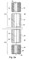
- Fig. 2a shows a further embodiment of the invention, in which both the first dowel 60 and the second dowel 70 are made in two parts.
- the first dowel 60 is divided into a first dowel top 62 having a first upper dowel inner hole 82 and a first dowel bottom 64 having a first lower dowel inner hole 84 and the first dowel top 62 and the first dowel bottom 64 are each configured as individual workpieces.
- the second dowel 70 are divided into a second dowel upper part 72 with a second upper dowel inner hole 92 and a second dowel lower part 74 with a second lower dowel inner hole 94 and the second dowel upper part 72 and the second dowel lower part 74 are each designed as individual workpieces.
- the first dowel upper part 62 and the second dowel upper part 62 are each 54 mm long with an outer diameter of 44 mm and a dowel inner diameter of 21.5 mm.
- the first dowel base 64 and the second dowel base 74 are 36 mm long with an outer diameter of 44 mm and a dowel inner diameter of 18 mm.
- the dowel inner hole 82 of the first dowel upper part 62 and the dowel inner hole 84 of the first dowel base 64 are not coaxial in this embodiment of the invention, ie the Dübelinnenlochachse 63 of the first Dübeloberteils 62 and Dübelinnenlochachse 65 of the first Dübelunterteils 64 are shifted from each other and Dübellinnenlochachse 63 of the first Dübeloberteils 62 and the Dübelinnenlochachse 65 of the first dowel base 64 are eccentric.
- the dowel inner hole 92 of the second dowel upper part 72 and the dowel inner hole 94 of the second dowel base 84 in this embodiment of the invention is not coaxial, ie the dowel inner axis 73 of the second dowel top 72 and the dowel inner axis 75 of the second dowel base 74 are offset from each other and the Dübellinnenlochachsen 73, 75 are eccentric.
- the dowel inner hole axis 63 of the first dowel top 62 and the dowel inner axis 73 of the second dowel top 72 and the dowel inner axis 65 of the first dowel upper 64 and the dowel inner axis 75 second dowel base 74 by about 1 mm against the respective dowel axes of the workpieces, with the axes of the Boreholes coincide, be shifted.
- the first dowel upper part 72 is rotated against the first dowel base 62 and the second dowel upper part 74 against the second dowel base 72 then for connection to the eccentricities, for example by 15 ° in the first hole 40 and in the second hole 50.
- the eccentricities of the first dowel 60th can then be additionally installed twisted against the eccentricities of the second dowel 70.
- polyethylene with about 8.9 weight percent silicate particles can be used for the material of the first dowel 60 and the second dowel 70.
- the connection system 10 is made together with a pin 110 made of steel having a length of 180 mm and a diameter of 18 mm and a sleeve 100 made of steel with a sleeve inner diameter of 18 mm, a sleeve outer diameter of 21.5 mm and a length of 108 mm educated.
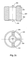
- Fig. 2b is the dowel top 230
- the dowel shells 62, 72 off Fig. 2a corresponds individually to the first or second dowel
- Fig. 2c is the dowel base 220
- the dowel bases 64, 74 off Fig. 2a corresponds individually to the first or second dowel.
- the dowel base 220 is provided with springs 232 which can engage in the grooves 222 of the dowel top 230 and so prevent twisting the dowel shells 230 against the dowel bases 220.
- Fig. 3 shows the connection system 10 Fig. 1 in composite form.
- the pin 110 is fully inserted into the sleeve 100.
- the pin 110 and the sleeve 100 are held by forces (F) in this position, which are exerted by the first dowel 60 and the second dowel 70 on the sleeve 100.
- Fig. 4 shows an embodiment of the invention in which the Dübelinnenlochachse 63 of the first Dübeloberteils 62 and Dübelinnenlochachse 65 of the first Dübelunterteils 64 and the Dübelinnenlochachse 73 of the second Dübeloberteils 72 and Dübelinnenlochachse 75 of the second Dübelunterteils 74 are not formed coaxially. In this way, a greater force is exerted on the sleeve 100.
- a pin 110 has a change 810 as in the detail view in FIG Fig. 9c is shown.
- the pin 110 has an outer diameter of 18 8 mm.
- the depth (3.5 mm) of the modification 810 is greater than the eccentricity of the dowel inner hole axes of the associated dowel 60, 70.
- Two embodiments of the dowel 110 are shown in FIG Fig. 9b shown.
- Both embodiments of the pin 910 and 920 have longitudinal grooves 930 on the surface of the pin. In one embodiment of the pin 910, these longitudinal grooves 930 are deep in another embodiment of the pin 920, these longitudinal grooves 930 are flat.
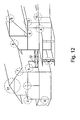
- FIG. 12 shows a system 1000 comprising two components 1010 and 1020 with pre-assembled dowels 1030, sleeves 1040 and pins 1050.
- the dowels 1030, sleeves 1040 and pins 1050 may be pre-mounted in one of the components 1010 and 1020 - eg in the factory for the components - and the components 1010, 1020 may then be quickly assembled on site.
- FIG. 11 Another embodiment of system 1000 is in Fig. 11 displayed.
- a wall is constructed of a plurality of components 1110, with dowels, pins and sleeves - together with 1120 in this example - pre-assembled on the components 1110.
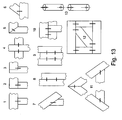
- FIG. 12 A house - or another type of building - is in Fig. 12 displayed.
- Various examples of interconnecting devices 1110 with interconnect systems according to the invention are shown.
- Fig. 13 shows the in Fig. 12 enlarged connections shown.
- connection system 20 First component 30 Second component 40 First hole 50 Second hole 60 First dowel 62 First dowel shell 63 Dowel inner hole axis of the first dowel shell 64 First dowel base 65 Dowel inner hole axis of the first dowel base 66 connecting piece 70 Second dowel 72 Second dowel shell 73 Dowel inner hole axis of the second dowel shell 74 Second dowel base 75 Dowel inner hole axis of the second dowel base 76 connecting piece 80 First dowel hole 82 First upper dowel hole 84 First lower dowel hole 90 Second dowel hole 92 Second upper dowel hole 94 Second lower dowel hole 100 shell 110 pen 200 dowel 220 Dowel base 222 groove 225 Dowel hole diameter of the dowel base 230 Dowel shell 232 feather 240 barb 250 Dowel hole diameter of the dowel shell 255 connecting piece 300 dowel 301 Dowel pin hole axis of the dowel base 310 Dowel shell 315 Dowel hole diameter of the dowel shell 316 Dowel pin hole axis of the dowel shell 320 Dowel base 325 Do
Landscapes
- Engineering & Computer Science (AREA)
- Architecture (AREA)
- Physics & Mathematics (AREA)
- Electromagnetism (AREA)
- Civil Engineering (AREA)
- Structural Engineering (AREA)
- Joining Of Building Structures In Genera (AREA)
- Insertion Pins And Rivets (AREA)
- Tires In General (AREA)
- Moulds For Moulding Plastics Or The Like (AREA)
- Manipulator (AREA)
- Vehicle Body Suspensions (AREA)
Abstract
Description
Die Erfindung bezieht sich auf ein Verbindungssystem zur mechanischen Verbindung von mindestens zwei Bauelementen.The invention relates to a connection system for the mechanical connection of at least two components.
In der Verbindungstechnik ist eine Vielzahl von Verbindungssystemen z.B. zur Verbindung von Bauelementen wie Natur- oder Kunststeinen und Trägern aus Holz, oder Metall bekannt.In connection technology, a variety of connection systems, e.g. for connecting components such as natural or artificial stones and supports made of wood, or metal known.
Beim Hausbau werden Last tragende Wände oft aus Ziegelsteinen, die mit Zementmörtel verbunden sind, aufgebaut. Das Ergebnis ist eine steif verbundene Wand, die relativ inelastisch ist. Die Inelastizität der Verbindung macht derartige Wände anfällig für Schwingungen und Erschütterungen z.B. eines Erdbebens.In house building load-bearing walls are often built from bricks, which are connected with cement mortar. The result is a rigidly connected wall that is relatively inelastic. The inelasticity of the joint renders such walls susceptible to vibrations and shocks, e.g. an earthquake.
Der Aufbau gemörtelter Ziegelwände umfasst, zusätzlich zum Aufschichten der Ziegelsteine, einen Schritt der Zubereitung des Mörtels, einen Schritt der Aufbringung des Mörtels auf die Ziegelsteine und einen Schritt des Abbindens des Mörtels während dessen die Verbindung der Bauelemente gebildet wird. Der Schritt der Aufbringung des Mörtels muss innerhalb einer bestimmten Zeitspanne nach der Zubereitung des Mörtels durchgeführt werden bevor der Mörtel beginnt abzubinden. Das Aufschichten der Ziegelsteine ist auf eine bestimmte Anzahl von Reihen beschränkt, bevor weitere Reihen von Ziegelsteinen auf die Ziegelsteine, die durch den ausgehärteten Mörtel verbunden sind, aufgeschichtet werden können. Dies verursacht Verzögerungen auf Grund von Pausen beim Bau.The construction of mortared brick walls includes, in addition to laying the bricks, a step of preparing the mortar, a step of applying the mortar to the bricks, and a step of setting the mortar during which the bonding of the building elements is formed. The step of applying the mortar must be carried out within a certain period of time after the preparation of the mortar before the mortar starts to set. The layering of the bricks is limited to a certain number of rows before adding more rows of bricks to the bricks connected by the hardened mortar are, can be piled up. This causes delays due to breaks in construction.
Umweltbedingungen schränken die Verarbeitung des Mörtels ebenfalls ein, z.B. liegt die typische Verarbeitungstemperatur von Zementmörtel oberhalb von 5 °C. Temperaturen unterhalb von 0 °C stellen ein Problem dar, da das Wasser, das für gewöhnlich für die Zubereitung des Mörtels benutzt wir, gefiert. Zusätzlich können auch erhöhte Temperaturen und Luftfeuchtigkeit die Eigenschaften und die Verarbeitung bestimmte Mörtel beeinflussen.Environmental conditions also limit the processing of the mortar, e.g. the typical processing temperature of cement mortar is above 5 ° C. Temperatures below 0 ° C are a problem as the water used to prepare the mortar is usually used. In addition, increased temperatures and humidity can affect the properties and processing of certain mortars.
Die Lage der einzelnen Ziegelsteine wird durch die Positionierung beim Aufschichten bestimmt. Deshalb ist, zur Erzielung einer akkuraten Wand, eine gewisse handwerkliche Fertigkeit notwendig und teure, ausgebildete Arbeitskräfte werden benötigt.The position of the individual bricks is determined by the positioning when stacking. Therefore, to achieve an accurate wall, some crafting skills are needed and expensive, skilled workers are needed.
Die Bauelemente von inneren und/oder nicht-Last-tragenden Wänden werden heutzutage häufig mit Klebstoff verbunden. Für die Verarbeitung von Klebstoff gelten ähnliche Einschränkungen wie oben im Zusammenhang mit der Verarbeitung von Mörtel diskutiert.The components of internal and / or non-load-bearing walls are now often connected with adhesive. For the processing of adhesive apply similar restrictions as discussed above in connection with the processing of mortar.
Insbesondere im Do-It-Yourself-Bereich gibt es eine Reihe von Systemen für Innenwände mit Positioniervorrichtungen, die dabei helfen die Bauelemente relativ zueinander zu positionieren. Derartige Positioniervorrichtungen, z.B. Nut- und Federsysteme, müssen an die Bauelemente bei deren Herstellung angebracht werden. Auf einer Baustelle können die kompletten geformten Bauelemente dann zusammengefügt und z.B. mit Klebstoff verbunden werden.Especially in do-it-yourself, there are a number of systems for inner walls with positioning devices, which help to position the components relative to each other. Such positioning devices, e.g. Tongue and groove systems must be attached to the components during their manufacture. At a construction site, the complete molded components can then be joined together and e.g. be connected with adhesive.
Klebstoff-freie Verbindungen von Bauelementen sind z.B. aus dem Bereich der Holzverbindungen bekannt. Eine Vielzahl unterschiedlicher Zapfenverbindungen ist z.B. aus dem Schreinerhandwerk bekannt, so z.B. die Schwalbenschwanzverbindung, die eine ineinandergreifende Verbindung zweier Bauelemente ermöglicht.Adhesive-free compounds of components are known, for example from the field of wood joints. A variety of different pin connections is known, for example from the carpentry, such as the dovetail connection, which allows an interlocking connection of two components.
Die Verwendung von Klebstoff-freien Dübelverbindungen ist ebenfalls für Bauelemente aus Holz bekannt. Das deutsche Patent
Schraubenartige Verbindungssysteme sind sehr universell einsetzbar. Ein Problem mit derartigen Verbindungssystemen ist die Zugänglichkeit zu Schraubenkopf und -mutter, z.B. wenn eine Mehrzahl von Reihen von Bauelementen wie z.B. Bausteinen zusammengefügt wird, um eine Wand zu bilden. Die Unterseite eines Bausteins ist, nach Befestigung der Reihe, nicht mehr leicht zugänglich. Ein weiteres Problem ist das zufällige Lockern von schraubenartigen Verbindungen. Ein Zugang zu Schrauben, die entlang der Baurichtung der Mauer eingefugt sind, ist nicht mehr möglich, wenn die Wand fertig gestellt ist.Helical connection systems are very universally applicable. A problem with such connection systems is the accessibility to the screw head and nut, e.g. when a plurality of rows of devices such as e.g. Building blocks is assembled to form a wall. The underside of a building block is no longer easily accessible after fixing the row. Another problem is the accidental loosening of screw-type connections. An access to screws, which are inserted along the construction direction of the wall, is no longer possible when the wall is completed.
Probleme mit der Zugänglichkeit zu Schraubenkopf und-mutter und möglichen Positionen für Schrauben haben zu Lösungen geführt, wie sie in der Europäischen Patentanmeldung
Nachteilig für die in den Patenten '769 und '687 beschriebenen Systeme ist, dass beide zusätzliche Verbindungselemente zu den Bauelementen hinzufügen. Diese Verbindungselemente selber sind eher kompliziert aufgebaut.A disadvantage of the systems described in the '769 and' 687 patents is that both add additional connectors to the components. These fasteners themselves are rather complicated.
Einen anderen Ansatz für ein mörtelfreies Verfahren zur Errichtung von Ziegelsteinwänden stellt ein schraubenartiges Verbindungssystem für Bausysteme dar, wie es in der Europäischen Patentanmeldung
In der deutschen Offenlegungsschrift
Es ist deshalb eine Aufgabe der Erfindung ein vielseitig nutzbares, stabiles Verbindungssystem für verschiedene Arten von Bauelementen zur Verfügung zu stellen.It is therefore an object of the invention to provide a versatile, stable interconnect system for various types of devices.
Es ist eine weitere Aufgabe eine Verbindung von Bauelementen zu ermöglichen, die eine elastische Bewegung der Bauelemente gegeneinander ermöglicht.It is a further object to allow a connection of components that allows an elastic movement of the components against each other.
Es ist eine weitere Aufgabe der Erfindung ein Verbindungssystem, das einen schnellen und effizienten Aufbau von Bauwerken wie z.B. Häusern auch unter schwierigen Umweltbedingungen ermöglicht, zur Verfügung zu stellen.It is a further object of the invention to provide a connection system which permits fast and efficient construction of structures such as e.g. Houses even under difficult environmental conditions allows to provide.
Diese Aufgaben werden durch die Bereitstellung eines Verbindungssystems zur Befestigung eines ersten Bauelements mit einem zweiten Bauelement gelöst. Das Verbindungssystem umfasst einen ersten Dübel mit einem ersten Dübelinnenloch mit einer ersten Dübelinnenlochachse, der befestigbar in ein erstes Loch mit einer ersten Lochachse in einem ersten Bauelement gesteckt wird, und einem zweiten Dübel mit einem zweiten Dübelinnenloch mit einer zweiten Dübelinnenlochachse, der befestigbar in ein zweites Loch mit einer zweiten Lochachse in einem zweiten Bauelement gesteckt wird. Das Dübelinnenloch des ersten Dübels und des zweiten Dübels weist jeweils ein oberes Dübelinnenloch im oberen Dübelteil mit einem oberen Dübelinnenlochradius und einer oberen Dübelinnenlochachse und ein unteres Dübelinnenloch im unteren Dübelteil mit einem unteren Dübelinnenlochradius und einer unteren Dübelinnenlochachse auf. Der obere Dübelinnenlochradius ist größer als der untere Dübelinnenlochradius. Die Dübelinnenlochachse des ersten Dübeloberteils und die Dübelinnenlochachse des ersten Dübelunterteils sowie die Dübelinnenlochachse des zweiten Dübeloberteils und die Dübelinnenlochachse des zweiten Dübelunterteils sind nicht koaxial ausgebildet, um das gesamte Verbindungssystem mit den Bauelementen zu verkanten, indem die Hülse und der Stift deformiert und gegen die jeweilige Dübelwand gepreßt werden. Eine Hülse mit einem inneren und einem äußeren Hülsenradius wird zwischen die Dübel in das erste Dübelinnenloch und das zweite Dübelinnenloch gesteckt. Ein Stift mit einem Stiftradius wird in die Hülse gesteckt. Der Stift kann zwischen die Dübel in das erste und zweite untere Dübelinnenloch gesteckt werden.These objects are achieved by the provision of a connection system for fastening a first component to a second component. The connection system comprises a first dowel having a first dowel inner hole with a first dowel inner hole axis which is fastened in a first hole with a first hole axis inserted in a first component, and a second dowel with a second dowel inner hole with a second dowel inner hole axis, which can be fastened in a second Hole is inserted with a second hole axis in a second component. The dowel inner hole of the first dowel and the second dowel each has an upper dowel inner hole in the upper dowel part with an upper Dübelinnenlochradius and an upper Dübelinnenlochachse and a lower Dübelinnenloch in the lower dowel part with a lower Dübelinnenlochradius and a lower Dübelinnenlochachse. The upper dowel inner hole radius is larger than the lower dowel inner hole radius. The Dübelinnenlochachse the first dowel upper part and Dübelinnenlochachse the first dowel base and Dübelinnenlochachse the second dowel shell and Dübelinnenlochachse the second Dübelunterteils are not coaxial to tilt the entire connection system with the components by the sleeve and the pin deformed and pressed against the respective dowel wall. A sleeve having an inner and an outer sleeve radius is inserted between the dowels in the first dowel inner hole and the second dowel inner hole. A pin with a pin radius is inserted into the sleeve. The pin can be inserted between the dowels in the first and second lower dowel hole.
Die Verwendung eines erfindungsgemäßen Verbindungssystems erlaubt die Verbindung von Bauelementen aus einer Vielzahl von Arten von Materialien, die hinreichend stabile Bohrlöcher ermöglichen. Die Materialien für den Dübel, die Hülse und den Stift können in ihrer Struktur, z.B. der Oberflächenstruktur angepasst werden. Die Materialien für den Dübel, die Hülse und den Stift können auch in Ihren Eigenschaften wie z.B. Elastizität an die Materialien aus denen die Bauelemente bestehen angepasst werden. Der typische Durchmesser der Löcher liegt in einem Bereich, der effiziente Bohrung von Löchern in den Materialien der Bauelemente erlaubt.The use of a connection system according to the invention allows the connection of components of a variety of types of materials, which allow sufficiently stable holes. The materials for the dowel, sleeve and pin may be in their structure, e.g. be adapted to the surface structure. The materials for the dowel, the sleeve and the pin can also be used in their properties, e.g. Elasticity to the materials from which the components are made to be adjusted. The typical diameter of the holes is in an area that allows efficient hole drilling in the materials of the devices.
Die Bewegung miteinander verbundener Bauelemente gegeneinander wird hauptsächlich durch die elastischen Eigenschaften der Verbindung bestimmt, da die Verbindung zwischen den Bauelementen nur durch die Verbindungssysteme an bestimmten Punkten entsteht, sowie zusätzlich durch die Reibungskräfte der zwischen den verbundenen Bauelementen. Insbesondere können die elastischen Eigenschaften dieser Verbindungen im Zusammenhang mit den verwendeten Materialien für die Verbindungssysteme eingestellt werden. Dadurch ist der Bau einer nicht-steifen Wand möglich, die insbesondere für Gebäude in erdbebengefährdeten Gebieten geeignet ist.The movement of interconnected components against each other is mainly determined by the elastic properties of the connection, since the connection between the components arises only through the connection systems at certain points, and additionally by the frictional forces between the connected components. In particular, the elastic properties of these compounds can be adjusted in connection with the materials used for the connection systems. As a result, the construction of a non-rigid wall is possible, which is particularly suitable for buildings in earthquake-prone areas.
Bauen mit dem offenbarten Verbindungssystem ist unabhängig von der Umgebungstemperatur. Die Bauelemente können vor dem Transport zu einer Baustelle oder direkt auf der Baustelle mit Löchern versehen werden. Der Zusammenbau der Bauelemente kann von ungelernten Arbeitskräften durchgeführt werden. Das Abwarten auf das Aushärten des Mörtels entfällt.Building with the disclosed connection system is independent of the ambient temperature. The components can be provided with holes before being transported to a construction site or directly on the construction site. The assembly of the components can be carried out by unskilled workers. Waiting for the curing of the mortar deleted.
Die Verbindung kann z.B. durch Biegung des Stifts und der Hülse in einem stumpfen Winkel gebildet werden. Die resultierenden elastischen Kräften und plastischen Verformungen im Verbindungssystem verzahnen das Verbindungssystem zusammen mit den Bauelementen.The connection can be formed, for example, by bending the pin and the sleeve at an obtuse angle. The resulting elastic forces and plastic deformations in the connection system interlock the connection system together with the components.
Die Verbindung wird durch Deformation der Hülse und des Stifts durch eine Exzentrizität einer oberen Dübellochachse gegen eine untere Dübellochachse gebildet . Dadurch werden die Hülse und der Stift gegen die Dübelwand gepresst und verkanten das gesamte Verbindungssystem mit den Bauelementen.The connection is formed by deformation of the sleeve and the pin by an eccentricity of an upper dowel axis against a lower Dübellochachse. As a result, the sleeve and the pin are pressed against the dowel wall and tilt the entire connection system with the components.
Die Verbindung wird durch Deformationen und Verspannungen gebildet, die durch nicht Übereinstimmung der Dübelinnenlochachsen des eingebauten ersten Dübels mit den Dübelinnenlochachsen des zweiten Dübels hervorgerufen wird.The connection is formed by deformations and tension, which is caused by mismatch of Dübelinnenlochachsen the built-in first dowel with the Dübelinnenlochachsen the second dowel.
Die Verbindung kann durch Deformationen und Verspannungen gebildet werden, die z.B. durch Zusammenpressung von Hülse, Dübel und Stift, z.B. bei Einstecken des Stiftes in einen konisch verlaufendes Dübelinnenloch entstehen, wenn z.B. der Stift einen größeren Durchmesser besitzt als das konisch verlaufende Dübelinnenloch bei der entsprechenden Einstecktiefe.The connection can be formed by deformations and tensions, e.g. by compressing sleeve, dowel and pin, e.g. upon insertion of the pin into a tapered dowel inner hole, when e.g. the pin has a larger diameter than the tapered Dübelinnenloch at the appropriate insertion depth.
-
Fig. 1 zeigt ein erfindungsgemäßes Verbindungssystem in zerlegter Form 20Fig. 1 shows a connection system according to the invention in disassembledform 20 -
Fig. 2a zeigt zwei zweiteilige Dübel für das VerbindungssystemFig. 2a shows two two-piece dowels for the connection system -
Fig. 2b zeigt das Dübeloberteil ausFig. 2a Fig. 2b shows the dowel shellFig. 2a -
Fig. 2c zeigt das Dübelunterteil ausFig. 2a Fig. 2c shows the dowel baseFig. 2a -
Fig. 3 zeigt ein Verbindungssystem in zusammengesetzter FormFig. 3 shows a connection system in composite form -
Fig. 4 zeigt ein weiteres Beispiel eines Verbindungssystems in zusammengesetzter Form 25Fig. 4 shows another example of a compound system in compound form 25 -
Fig. 5 zeigt ein Beispiel eines erfindungsgemäßen DübelsFig. 5 shows an example of a dowel according to the invention -
Fig. 6 zeigt ein weiteres Beispiel eines erfindungsgemäßen DübelsFig. 6 shows a further example of a dowel according to the invention -
Fig. 7 zeigt ein weiteres Beispiel eines erfindungsgemäßen DübelsFig. 7 shows a further example of a dowel according to the invention -
Fig. 8 zeigt ein Beispiel einer erfindungsgemäßen HülseFig. 8 shows an example of a sleeve according to the invention -
Fig. 9a zeigt ein Beispiel eines erfindungsgemäßen Stiftes 30Fig. 9a shows an example of apin 30 according to the invention -
Fig. 9b zeigt ein weiteres Beispiel eines erfindungsgemäßen StiftesFig. 9b shows another example of a pen according to the invention -
Fig. 9c zeigt zwei weitere Beispiele eines erfindungsgemäßen StiftesFig. 9c shows two further examples of a pen according to the invention -
Fig. 10 zeigt vier erfindungsgemäß verbundene BauelementeFig. 10 shows four components connected according to the invention -
Fig. 11 zeigt eine Wandkonstruktion mit Einsatz des Verbindungssystems der ErfindungFig. 11 shows a wall construction with use of the connection system of the invention -
Fig. 12 zeigt ein Bauwerk aufgebaut mit Einsatz des Verbindungssystems der ErfindungFig. 12 shows a building constructed using the connection system of the invention -
Fig. 13 zeigt eine Vielzahl von Verbindungen mit dem erfindungsgemäßen Verbindungssystem.Fig. 13 shows a variety of connections with the connection system according to the invention.
In einer bevorzugten Ausführungsform der Erfindung sind der erste Dübel 60 und der zweite Dübel 70 in zwei Bereiche unterteilt. Der erste Dübel 60 hat ein erstes Dübeloberteil 62 und ein erstes Dübelunterteil 64. Das erste Dübeloberteil 62 schließt an die Oberfläche des ersten Bauelements 20 an und das erste Dübelunterteil 64 ist innerhalb des ersten Bauelements 20. Das erste Dübeloberteil 62 und das erste Dübelunterteil 64 sind über ein konisch verlaufendes Zwischenstück 66 verbunden. Der Dübelinnenlochdurchmesser des ersten Dübeloberteils 62 ist größer als der Dübelinnenlochdurchmesser des ersten Dübelunterteils 64.In a preferred embodiment of the invention, the
In gleicher Weise besitzt der zweite Dübel 70 ein zweites Dübeloberteil 72 und ein zweites Dübelunterteil 74. Das zweite Dübeloberteil 72 schließt an die Oberfläche des zweiten Bauelements 30 an und das zweite Dübelunterteil 74 ist innerhalb des zweiten Bauelements 30. Das zweite Dübeloberteil 72 und das zweite Dübelunterteil 74 sind über ein konisch verlaufendes Zwischenstück 76 verbunden. Der Dübelinnenlochdurchmesser des zweiten Dübeloberteils 72 ist größer als der Dübelinnenlochdurchmesser des zweiten Dübelunterteils 74.In the same way, the
Die Länge des ersten Dübeloberteils 62 und des zweiten Dübeloberteils 72 sind im Wesentlichen gleich und sind in
Eine Hülse 100 ist in das erste Dübelinnenloch 80 bis zu einer Tiefe von etwa 1/3D eingesteckt und ein Stift 110 ist in das zweite Loch 50 eingesteckt. Die Hülse 100 ist typischerweise als Hohlzylinder ausgebildet. Der Stift 110 kann z.B. als Hohlzylinder oder als Vollzylinder ausgebildet sein.A
In einer exemplarischen Ausführungsform der Erfindung sind das erste Bauelement 20 und das zweite Bauelement 30 Betonplatten. Der erste Dübel 60 und der zweite Dübel 70 sind aus Kunststoff oder Silikatpolymer. Einem Kunststoff wie z.B. Polyethylen können dabei z.B. Silikatpartikel beigefügt werden, um eine Silikatannierung zu bilden. Der erste Dübel 60 und der zweite Dübel 70 können für eine verbesserte Verbindung auch mit einer Keramikbeschichtung versehen werden. Durch diese Keramikbeschichtung oder Silikatarmierung kann z.B. die Reibung zwischen den betreffenden Bauelementen 20 und 30, den betreffenden Dübeln 60 und 70, und der betreffenden Hülse 100 und dem betreffenden Stift 110 erhöht werden.In an exemplary embodiment of the invention, the
Das erste Dübeloberteil 62 und das zweite Dübeloberteil 72 haben eine Länge von 120 mm, einen Dübelinnenlochdurchmesser von 25,8 mm und einen Dübelaußendurchmesser von 49,6 mm. Das erste Dübelunterteil 64 und das zweite Dübelunterteil 74 haben eine Länge von 80 mm, einen Dübelinnenlochdurchmesser von 20,2 mm und einen Dübelaußendurchmesser von 49,6 mm. Der Stift 110 ist aus Stahl St37 gefertigt mit einer Länge von 398 mm und einem Durchmesser von 19 mm. Das erste Loch 40 und das zweite Loch 50 haben einen Lochdurchmesser von 50 mm und eine Tiefe von 200 mm. Die Hülse 100 ist aus Stahl St37 gefertigt mit einem Hülseninnendurchmesser von 19,8 mm, einem Hülsenaußendurchmesser von 25 mm und einer Länge von 238 mm. Diese Dimensionierungen sind nur beispielhaft und die Erfindung ist nicht auf diese Dimensionen beschränkt.The first dowel
In einer Ausführungsform der Erfindung sind der erste Dübel 60 und der zweite Dübel 70 aus einem Stück gefertigt. In einer anderen Ausführungsform der Erfindung ist der erste Dübel 60 und der zweite Dübel 70 aus jeweils zwei Stücken gefertigt, entsprechend den Dübeloberteilen 62 und 72 und den Dübelunterteilen 64 und 74. Der zweiteilige Dübel ist unter Herstellungsgesichtspunkten eventuell leichter zu fertigen.In one embodiment of the invention, the
In
Weitere Ausführungsformen des Verbindungssystems sind in den
- 1. Beispiel (
Fig. 5 ):Das Dübeloberteil 230 hat eine Länge von 55 mm, einen konisch sich von 24mm auf 21,5mm verjüngenden Dübelinnenlochdurchmesser 250, der dann auf einer weiterenLänge von 11 mm bei einem konstanten Wertvon 21,5 mm verbleibt und einen Dübelaußendurchmesser von 44 mm.Das Dübelunterteil 220 hat eine Länge von 33 mm, einen konisch sich von 19 mm auf 18mm verjüngenden Dübelinnenlochdurchmesser 225 und einen Dübelaußendurchmesser von 44 mm. Der Übergangzwischen dem Dübeloberteil 230und dem Dübelunterteil 220 ist über ein konisch verlaufendes Zwischenstück 255 auf einer Länge von etwa 1 mm realisiert.Das Dübelunterteil 220 kann eingeschlitzt sein. - 2. Beispiel (
Fig. 6 ):Das Dübeloberteil 310 hat eine Länge von 55 mm,einen Dübelinnenlochdurchmesser 315 von 24 mm und einen Dübelaußendurchmesser von 44 mm.Das Dübelunterteil 320 hat eine Länge von 33 mm,einen Dübelinnenlochdurchmesser 325 von 18 mm und einen Dübelaußendurchmesser von 44 mm. Der Übergangzwischen dem Dübeloberteil 310und dem Dübelunterteil 320 ist über ein konisch verlaufendes Zwischenstück 330 auf einer Länge von etwa 3 mm realisiert.Die Dübelinnenlochachse 301 desDübelunterteils 320 ist um 2 mm gegen dieDübelinnenlochachse 316 desDübeloberteils 310, die der Dübelachse entspricht, die in dieser Ausführungsform mit der Lochachse zusammenfällt, verschoben. Die Lage der Achsen wird in der Querschnittszeichnung inFig. 6 veranschaulicht. - 3. Beispiel: Bei den
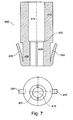
Maßen des Dübels 200 aus dem ersten Beispiel (Fig. 5 )ist das Dübelinnenloch 415 desDübeloberteils 410und das Dübelinnenloch 425 desDübelunterteils 420 exzentrisch gegenden Dübel 400 versetzt. D.h. diegemeinsame Achse 416 eines oberen Dübelinnenloch 415 und eines unteren Dübelinnenlochs 425 ist zum Beispiel um etwa 2 mm gegen dieDübelachse 401 versetzt, wie in der Querschnittszeichnung vonFig. 7 veranschaulicht ist.Wird dieser Dübel 400 im erfindungsgemäßen Verbindungssystem eingesetzt, fällt dieDübelachse 401 mit der Lochachse zusammen. Beim Einsatz der Ausführungsforin desDübels 400 als ersterDübel 60 und als zweiter Dübel 70 sind der erste Dübel 60 und der zweite Dübel 70 zur Bildung der Verbindung gegeneinander um 15° verdreht, d.h. mit nicht übereinstimmender Ausrichtung der Exzentrizitäten der gemeinsamen Achse 416im ersten Dübel 60 und der gemeinsamen Achse 416im zweiten Dübel 70, in das erste und zweite Loch gesteckt.
- 1st example (
Fig. 5 Thedowel top 230 has a length of 55 mm, a conically tapering from 24 mm to 21.5 mm dowelinner diameter 250, which then remains on a further length of 11 mm at a constant value of 21.5 mm and a dowel outer diameter of 44 mm. Thedowel base 220 has a length of 33 mm, a conically tapering from 19 mm to 18mm Dübelinnenlochdurchmesser 225 and a dowel outer diameter of 44 mm. The transition between thedowel shell 230 and thedowel base 220 is over realized conically extendingintermediate piece 255 on a length of about 1 mm. Thedowel base 220 may be slit. - 2nd example (
Fig. 6 ): Thedowel top 310 has a length of 55 mm, a dowelinner diameter 315 of 24 mm and a dowel outer diameter of 44 mm. Thedowel base 320 has a length of 33 mm, a dowelinner diameter 325 of 18 mm and a dowel outer diameter of 44 mm. The transition between the dowelupper part 310 and thedowel base 320 is realized via a conically extendingintermediate piece 330 over a length of about 3 mm. The dowelinner axis 301 of thedowel base 320 is displaced by 2 mm against the dowelinner axis 316 of thedowel top 310, which corresponds to the dowel axis, which in this embodiment coincides with the axis of the hole. The position of the axes is shown in the cross section drawing inFig. 6 illustrated. - Example 3: For the dimensions of the
plug 200 from the first example (Fig. 5 ), the dowelinner hole 415 of the dowel upper 410 and the dowelinner hole 425 of thedowel base 420 is eccentrically offset from thedowel 400. That is, thecommon axis 416 of an upper dowelinner hole 415 and a lower dowelinner hole 425 is offset, for example, by about 2 mm against thedowel axis 401, as in the cross-sectional drawing ofFig. 7 is illustrated. If thisanchor 400 is used in the connection system according to the invention, thedowel axis 401 coincides with the hole axis. When using the Ausführungsforin thedowel 400 as thefirst dowel 60 andsecond dowel 70, thefirst dowel 60 and thesecond dowel 70 are rotated to form the connection against each other by 15 °, ie with mismatched alignment of the eccentricities of thecommon axis 416 in thefirst dowel 60 and thecommon axis 416 in thesecond dowel 70, inserted into the first and second holes.
Drei weitere Ausführungsfonnen des Stifts sind in
Eine andere Ausführung des Systems 1000 ist in
Ein Haus - oder eine andere Art von Bauwerk - ist in
C Tiefe der Löcher
F KräfteD Length of dowel shells
C depth of holes
F forces
Claims (18)
- A linking system (10) for fixing a first building element (20) to a second building element (30), the linking system (10) comprising:i. a first dowel (60) with a first dowel internal orifice (80) with at least one first dowel internal orifice axis (63, 65), which is fixedly insertable in a first hole (40) with a first hole axis in the first building element (20),ii. a second dowel (70) with a second dowel internal orifice (90) with at least one second dowel internal orifice axis (73, 75) which is fixedly insertable in a second hole (30) with a second hole axis in the second building element,iii. whereby the dowel internal orifice (80, 90) of the first dowel (60) and the second dowel has respectively an upper dowel internal orifice (82, 92) in the upper dowel section (62, 72) with an upper dowel internal orifice radius and an upper dowel internal orifice axis (63, 73) and a lower dowel internal orifice (84, 94) in the lower dowel section (64, 74) with a lower dowel internal orifice radius and a lower dowel orifice axis (65, 75), whereby the upper dowel internal orifice radius is larger than the lower dowel internal orifice radius,iv. a sleeve (100, 1040) positioned between the first dowel (60) and the second dowel (70) with an inner sleeve radius and an outer sleeve radius, which can be placed between the dowels (60, 70) respectively in the first and second upper dowel inner orifice (82, 92), andv. a rod (110, 910, 920, 1050), which can be positioned in the sleeve (100), placed between the dowels (60, 70) in the first and second lower dowel internal orifice (84, 94), and having a rod radius,
characterised in that the dowel internal orifice axis (63) of the dowel upper sections (62) and the dowel internal orifice axis (65) of the first dowel lower section (64) as well as the dowel internal orifice axis (73) of the second dowel upper section (72) and the dowel internal orifice axis (75) of the second dowel lower section (74) are not coaxially arranged, in order that the complete linking system (10) with the building elements (20, 30) are twisted, such that the sleeve (100) and the rod (110, 910, 920, 1050) are deformed and pressed against the respective dowel wall. - A linking system (10) according to claim 1, whereby the dowel upper section (62, 72, 230, 310, 410) and the dowel lower section (64, 74, 220, 320, 420) before linking of the first with the second building element (20, 30) form a continuous tool.
- A linking system (10) according to claim 1, whereby the dowel upper section (62, 72, 230, 310, 410) and the dowel lower section (64, 74, 220, 320, 420) prior to the connection of the first with the second building element (20, 30) are separate tools.
- A linking system (10) according to claims 1-3 in which the dowel internal orifice (415) of the first dowel upper section (62) and/or the second dowel upper section (72) and/or the dowel internal orifice (425) of the first dowel lower section (64) and/or the second dowel lower section (74) are conically tapered over at least a part of their length.
- A linking system (10) according to claim 1, in which the upper dowel internal orifice axis (63) of the first dowel and the axis of the first hole (40), in which the first dowel is placed, are coincident and the lower dowel internal orifice axis (65) of the first dowel are arranged eccentrically with respect to the upper dowel internal orifice axis (63) of the first dowel and the axis of the first hole (40) and/or the upper dowel internal orifice axis (73) of the second dowel (70) and the axis of the second hole (50), into which the second dowel (70) is placed, are coincident and the lower dowel internal orifice axis (75) of the second dowel (70) are arranged eccentrically with respect to the upper dowel internal orifice axis (73) of the second dowel (70) and the axis of the second hole (50).
- A linking system (10) according to claim 5 in which the axis of the first hole (40) in the first building element (20) is slightly tilted with respect to the normal of the surface about the first hole (40) in the first building element (20), into which the first dowel (60) is placed, and/or the access of the second hole (40) in the second building element (30) is slightly tilted with respect to the normal of the upper service about the second hole (50) in the second building element (30) in which the second dowel (70) is placed.
- A linking system (10) according to claim 5 in which the first dowel internal orifice axis is slightly sloped with respect to the axis of the first hole (40) in the first building element (20) in which the first dowel is placed, and/or the second dowel internal orifice axis is slightly sloped with respect to the axis of the second hole (50) in the second building element (30) in which the second dowel is placed.
- A linking system (10) according to one of the previous claims in which the first and/or the second dowel (60, 70) have barbs.
- A linking system (10) according to one of the previous claims in which one or more sleeves (100, 1040) are made from wood, plastic or metal.
- A linking system (10) according to one of the previous claims in which one or more sleeves (100, 1040) are made from steel.
- A linking system (10) according to one of the previous claims in which one or more rods (110, 800, 910, 920, 1050) are made from wood, plastic or metal.
- A linking system (10) according to claim 11, in which one or more rods (110, 800, 910, 920, 1050) are made from steel.
- A linking system (10) according to one of the previous claims in which one or more dowels (60, 70, 200, 300, 400, 1030) are made from wood, plastic or metal.
- A linking system (10) according to claim 13, in which one or more dowels (60, 70, 200, 300, 400, 1030) are made from polyethylene.
- A linking system (10) according to claim 13, in which one or more dowels (60, 70, 200, 300, 400, 1030) are manufactured from polyethylene and the dowel (60, 70, 200, 300, 400) comprises silicate particles.
- A linking of building elements (20, 30, 1010, 1020, 1110) with a plurality of linking systems (10) of one of the claims 1-15.
- A linking of building elements (20, 30, 1010, 1020, 1110) with a plurality of linking systems (10) according to claim 16, in which the linking systems are skewed with respect to each other.
- A construction having a first building element (20) and a second building element (30) in which the first building element (20) and the second building element (30) are held together by one ore more linking systems (10) according to one of the claims 1-15.
Priority Applications (1)
| Application Number | Priority Date | Filing Date | Title |
|---|---|---|---|
| PL05850766T PL1926864T3 (en) | 2005-08-20 | 2005-08-20 | Linking system for producing a link between building elements |
Applications Claiming Priority (1)
| Application Number | Priority Date | Filing Date | Title |
|---|---|---|---|
| PCT/IB2005/004044 WO2007049097A2 (en) | 2005-08-20 | 2005-08-20 | Linking system for producing a link between building elements |
Publications (3)
| Publication Number | Publication Date |
|---|---|
| EP1926864A2 EP1926864A2 (en) | 2008-06-04 |
| EP1926864B1 true EP1926864B1 (en) | 2011-10-12 |
| EP1926864B8 EP1926864B8 (en) | 2012-02-29 |
Family
ID=37968187
Family Applications (1)
| Application Number | Title | Priority Date | Filing Date |
|---|---|---|---|
| EP05850766A Not-in-force EP1926864B8 (en) | 2005-08-20 | 2005-08-20 | Linking system for producing a link between building elements |
Country Status (7)
| Country | Link |
|---|---|
| US (1) | US20110041447A1 (en) |
| EP (1) | EP1926864B8 (en) |
| AT (1) | ATE528454T1 (en) |
| DK (1) | DK1926864T3 (en) |
| ES (1) | ES2375489T3 (en) |
| PL (1) | PL1926864T3 (en) |
| WO (1) | WO2007049097A2 (en) |
Cited By (1)
| Publication number | Priority date | Publication date | Assignee | Title |
|---|---|---|---|---|
| WO2022207346A1 (en) | 2021-03-29 | 2022-10-06 | Neue Holzbau Ag Lungern | Connecting assembly for connecting two components in the field of construction |
Families Citing this family (9)
| Publication number | Priority date | Publication date | Assignee | Title |
|---|---|---|---|---|
| EP2476386B1 (en) | 2007-12-17 | 2013-06-12 | Synthes GmbH | Dynamic bone fixation element |
| CA2867269A1 (en) | 2012-03-13 | 2013-09-19 | DePuy Synthes Products, LLC | Dynamic bone fixation element |
| DE102012103591A1 (en) * | 2012-04-24 | 2013-10-24 | Matthias Holzberger | Connecting means for coupling two components |
| EP2935715B1 (en) * | 2012-12-21 | 2018-02-14 | Wembley Innovation Ltd | Reinforced blockwork construction method |
| JP6460952B2 (en) * | 2015-09-30 | 2019-01-30 | 鹿島建設株式会社 | Joining structure and joining method |
| CN108301568B (en) * | 2018-01-31 | 2019-07-26 | 合肥建工集团有限公司 | A kind of assembling structure of assembly concrete component |
| KR102190324B1 (en) * | 2018-11-12 | 2020-12-11 | 김태명 | A Set of Assemble-able Bricks |
| CN113530009B (en) * | 2021-07-30 | 2023-01-10 | 山东建筑大学 | Bow-shaped heat preservation connecting piece and building outer wall structure |
| AT525687B1 (en) * | 2021-12-01 | 2023-08-15 | Bauhuette Leitl Werke Ges M B H | Method of forming a masonry |
Citations (3)
| Publication number | Priority date | Publication date | Assignee | Title |
|---|---|---|---|---|
| DE3036627A1 (en) * | 1980-09-29 | 1982-05-19 | Alfons 6541 Biebern Rockenbach | Metal or plastics anchor bolt socket - has inclined tongues on outside gripping drilling wall once inserted |
| DE3338559A1 (en) * | 1983-10-24 | 1985-05-15 | Peter 6550 Bad Kreuznach Bussmer | Method of fastening a coupling bolt in a stone and devices for carrying out this method |
| DE3444465A1 (en) * | 1984-11-26 | 1986-06-19 | Fritz 7597 Rheinau Matthiß | Container having horizontal slats which are attached at intervals from top to bottom and transversely to the vertically upright posts |
Family Cites Families (24)
| Publication number | Priority date | Publication date | Assignee | Title |
|---|---|---|---|---|
| US2924006A (en) * | 1960-02-09 | Extractor tool | ||
| US1749547A (en) * | 1926-08-16 | 1930-03-04 | Martin T Ruddy | Dowel-pin construction |
| DE1107910B (en) * | 1957-03-26 | 1961-05-31 | Curt Weinert | Flexible duebel |
| US3067546A (en) * | 1959-09-22 | 1962-12-11 | Het Spoorwegbouwbedrijf Nv | Sleeve-shaped plug for a pin-shaped fastening member |
| US3099470A (en) * | 1962-02-08 | 1963-07-30 | Worthington Corp | Adjustable dowel |
| US3844697A (en) * | 1968-08-27 | 1974-10-29 | H Edwards | Tendon anchorage assembly with threaded support member for concrete formwork |
| DE2003011C3 (en) * | 1970-01-23 | 1974-05-16 | Gustav Konig | Precast slab connection |
| US4366651A (en) * | 1979-10-06 | 1983-01-04 | Newport Borough Council, Of Civic Centre | Fixing devices |
| CN1014217B (en) * | 1988-09-01 | 1991-10-09 | 国营清阳机械厂 | Translational regulating eccentric pin of combined clamp and structure |
| US5061137A (en) * | 1991-04-29 | 1991-10-29 | Ford Motor Company | Fastener with resilient linking means |
| US5413441A (en) * | 1993-07-19 | 1995-05-09 | United Industries Corporation | Hybrid eccentric wedge anchor |
| US5644889A (en) * | 1994-08-05 | 1997-07-08 | Dur-O-Wal, Inc. | Remedial wall anchor system |
| CA2158771C (en) * | 1995-09-21 | 1999-08-10 | David W. Fielding | Drywall construction and means therefor |
| US5813185A (en) * | 1996-04-29 | 1998-09-29 | Jackson; George W. | Spacer reciever for a wall form tie rod |
| FR2762251B1 (en) * | 1997-04-17 | 1999-06-04 | Daniel Choisel | ASSEMBLY DEVICE FOR WOODEN BOARDS CONSTITUENT OF CONSTRUCTION WALLS |
| USD459205S1 (en) * | 1999-02-05 | 2002-06-25 | Lee A. Shaw | Concrete dowel tube with clip |
| US20020078652A1 (en) * | 2000-12-27 | 2002-06-27 | Hawkes E. Gerry | Modular structural surface assembly |
| USD456700S1 (en) * | 2001-07-13 | 2002-05-07 | Miller Dowel Company | Dowel |
| US6641613B2 (en) * | 2002-01-30 | 2003-11-04 | Cortek, Inc. | Double dowel spinal fusion implant |
| DE20211288U1 (en) * | 2002-07-26 | 2003-12-04 | Fischerwerke Artur Fischer Gmbh & Co. Kg | connecting element |
| US7124547B2 (en) * | 2002-08-26 | 2006-10-24 | Bravinski Leonid G | 3-D construction modules |
| US6953300B2 (en) * | 2004-01-05 | 2005-10-11 | Ted Chen | Combining device for suspending object |
| US7241095B2 (en) * | 2005-04-07 | 2007-07-10 | Driv-Lok, Inc. | Dowel with locking features and method of using the same |
| US7975444B2 (en) * | 2007-11-29 | 2011-07-12 | Barsplice Products, Inc. | Coupler system for adjacent precast concrete members and method of connecting |
-
2005
- 2005-08-20 AT AT05850766T patent/ATE528454T1/en active
- 2005-08-20 DK DK05850766.6T patent/DK1926864T3/en active
- 2005-08-20 EP EP05850766A patent/EP1926864B8/en not_active Not-in-force
- 2005-08-20 ES ES05850766T patent/ES2375489T3/en active Active
- 2005-08-20 WO PCT/IB2005/004044 patent/WO2007049097A2/en active Application Filing
- 2005-08-20 PL PL05850766T patent/PL1926864T3/en unknown
- 2005-08-20 US US12/064,298 patent/US20110041447A1/en not_active Abandoned
Patent Citations (3)
| Publication number | Priority date | Publication date | Assignee | Title |
|---|---|---|---|---|
| DE3036627A1 (en) * | 1980-09-29 | 1982-05-19 | Alfons 6541 Biebern Rockenbach | Metal or plastics anchor bolt socket - has inclined tongues on outside gripping drilling wall once inserted |
| DE3338559A1 (en) * | 1983-10-24 | 1985-05-15 | Peter 6550 Bad Kreuznach Bussmer | Method of fastening a coupling bolt in a stone and devices for carrying out this method |
| DE3444465A1 (en) * | 1984-11-26 | 1986-06-19 | Fritz 7597 Rheinau Matthiß | Container having horizontal slats which are attached at intervals from top to bottom and transversely to the vertically upright posts |
Cited By (1)
| Publication number | Priority date | Publication date | Assignee | Title |
|---|---|---|---|---|
| WO2022207346A1 (en) | 2021-03-29 | 2022-10-06 | Neue Holzbau Ag Lungern | Connecting assembly for connecting two components in the field of construction |
Also Published As
| Publication number | Publication date |
|---|---|
| DK1926864T3 (en) | 2012-02-13 |
| ES2375489T3 (en) | 2012-03-01 |
| PL1926864T3 (en) | 2012-03-30 |
| EP1926864B8 (en) | 2012-02-29 |
| US20110041447A1 (en) | 2011-02-24 |
| WO2007049097A2 (en) | 2007-05-03 |
| EP1926864A2 (en) | 2008-06-04 |
| ATE528454T1 (en) | 2011-10-15 |
| WO2007049097A3 (en) | 2007-11-15 |
Similar Documents
| Publication | Publication Date | Title |
|---|---|---|
| EP1926864B1 (en) | Linking system for producing a link between building elements | |
| EP1929109B1 (en) | Tower construction | |
| DE19818525A1 (en) | Wood-concrete composite element | |
| DE202010007659U1 (en) | Insulating board and thermal insulation wall with such an insulation board | |
| DE102004030815B4 (en) | Connection system for mechanical connection of components | |
| DE102005040388A1 (en) | Wood and/or concrete carrying parts connection for e.g. timber panel construction, has dimensionally stable connection base inserted into sealing compound e.g. concrete, where base is made from wood, plastic and/or metal | |
| DE102013002104A1 (en) | Supporting structure made of wood with a first rod-shaped or planar support element and at least one second rod-shaped or sheet-like support element | |
| DE10229115B4 (en) | Connecting element for a double-shell masonry and masonry | |
| DE19539234A1 (en) | Wall member for building structures | |
| DE102005024828A1 (en) | fastening device | |
| DE10000059A1 (en) | Fastener for fixing faade elements on walls comprises plate holder with coil shaped part with tubular shaft and two plates and connected to positioning sleeve with openings for guiding through dowel sleeve | |
| DE3213953A1 (en) | Wall bond system | |
| DE202016105596U1 (en) | Structure and buildings | |
| EP3680569B1 (en) | Ventilation network | |
| AT510059B1 (en) | CONNECTING DEVICE FOR CONNECTING INTERCONNECTED OBJECTS AND CONSTRUCTION ELEMENT AND USE | |
| DE10133976A1 (en) | Connector plate for reinforcing adhesive joint between two pieces of wood is fitted into grooves in pieces which contain adhesive and has sloping hooks on each side which face bottom of groove | |
| DE862662C (en) | Construction | |
| DE2263027A1 (en) | COMPONENT COMPOSED FROM SHORT WOODEN PARTS | |
| DE202020103522U1 (en) | Thermal insulation composite system, facade with the thermal insulation composite system as well as tools for the construction of the same | |
| DE102020116153A1 (en) | Thermal insulation composite system, facade with the thermal insulation composite system as well as tools and methods for erecting the same | |
| WO2001065124A1 (en) | Arrangement and method for fixing objects | |
| DE102004006223A1 (en) | Prefabricated wall element | |
| DE29723866U1 (en) | Fastener | |
| DE69632747T2 (en) | TWO-PART BUILDING CONSTRUCTION IN CONCRETE AND MANUFACTURING METHOD | |
| DE202021100079U1 (en) | Kit for the construction of a building |
Legal Events
| Date | Code | Title | Description |
|---|---|---|---|
| PUAI | Public reference made under article 153(3) epc to a published international application that has entered the european phase |
Free format text: ORIGINAL CODE: 0009012 |
|
| AK | Designated contracting states |
Kind code of ref document: A2 Designated state(s): AT BE BG CH CY CZ DE DK EE ES FI FR GB GR HU IE IS IT LI LT LU LV MC NL PL PT RO SE SI SK TR |
|
| AX | Request for extension of the european patent |
Extension state: AL BA HR MK YU |
|
| 17P | Request for examination filed |
Effective date: 20080515 |
|
| RBV | Designated contracting states (corrected) |
Designated state(s): AT BE BG CH CY CZ DE DK EE ES FI FR GB GR HU IE IS IT LI LT LU LV MC NL PL PT RO SE SI SK TR |
|
| RIN1 | Information on inventor provided before grant (corrected) |
Inventor name: PHILIPP, FRANZ |
|
| 17Q | First examination report despatched |
Effective date: 20090225 |
|
| GRAP | Despatch of communication of intention to grant a patent |
Free format text: ORIGINAL CODE: EPIDOSNIGR1 |
|
| GRAS | Grant fee paid |
Free format text: ORIGINAL CODE: EPIDOSNIGR3 |
|
| GRAA | (expected) grant |
Free format text: ORIGINAL CODE: 0009210 |
|
| AK | Designated contracting states |
Kind code of ref document: B1 Designated state(s): AT BE BG CH CY CZ DE DK EE ES FI FR GB GR HU IE IS IT LI LT LU LV MC NL PL PT RO SE SI SK TR |
|
| DAX | Request for extension of the european patent (deleted) | ||
| REG | Reference to a national code |
Ref country code: GB Ref legal event code: FG4D Free format text: NOT ENGLISH |
|
| REG | Reference to a national code |
Ref country code: CH Ref legal event code: EP |
|
| RAP2 | Party data changed (patent owner data changed or rights of a patent transferred) |
Owner name: FACTUM GMBH |
|
| REG | Reference to a national code |
Ref country code: IE Ref legal event code: FG4D |
|
| REG | Reference to a national code |
Ref country code: DE Ref legal event code: R096 Ref document number: 502005012035 Country of ref document: DE Effective date: 20111208 |
|
| REG | Reference to a national code |
Ref country code: RO Ref legal event code: EPE |
|
| REG | Reference to a national code |
Ref country code: CH Ref legal event code: NV Representative=s name: FELBER & PARTNER AG PATENTANWAELTE |
|
| REG | Reference to a national code |
Ref country code: NL Ref legal event code: T3 |
|
| REG | Reference to a national code |
Ref country code: SE Ref legal event code: TRGR |
|
| REG | Reference to a national code |
Ref country code: DK Ref legal event code: T3 |
|
| REG | Reference to a national code |
Ref country code: ES Ref legal event code: FG2A Ref document number: 2375489 Country of ref document: ES Kind code of ref document: T3 Effective date: 20120301 |
|
| LTIE | Lt: invalidation of european patent or patent extension |
Effective date: 20111012 |
|
| REG | Reference to a national code |
Ref country code: PL Ref legal event code: T3 |
|
| REG | Reference to a national code |
Ref country code: SK Ref legal event code: T3 Ref document number: E 10925 Country of ref document: SK |
|
| PG25 | Lapsed in a contracting state [announced via postgrant information from national office to epo] |
Ref country code: LT Free format text: LAPSE BECAUSE OF FAILURE TO SUBMIT A TRANSLATION OF THE DESCRIPTION OR TO PAY THE FEE WITHIN THE PRESCRIBED TIME-LIMIT Effective date: 20111012 Ref country code: IS Free format text: LAPSE BECAUSE OF FAILURE TO SUBMIT A TRANSLATION OF THE DESCRIPTION OR TO PAY THE FEE WITHIN THE PRESCRIBED TIME-LIMIT Effective date: 20120212 |
|
| REG | Reference to a national code |
Ref country code: IE Ref legal event code: FD4D |
|
| PG25 | Lapsed in a contracting state [announced via postgrant information from national office to epo] |
Ref country code: PT Free format text: LAPSE BECAUSE OF FAILURE TO SUBMIT A TRANSLATION OF THE DESCRIPTION OR TO PAY THE FEE WITHIN THE PRESCRIBED TIME-LIMIT Effective date: 20120213 Ref country code: SI Free format text: LAPSE BECAUSE OF FAILURE TO SUBMIT A TRANSLATION OF THE DESCRIPTION OR TO PAY THE FEE WITHIN THE PRESCRIBED TIME-LIMIT Effective date: 20111012 Ref country code: GR Free format text: LAPSE BECAUSE OF FAILURE TO SUBMIT A TRANSLATION OF THE DESCRIPTION OR TO PAY THE FEE WITHIN THE PRESCRIBED TIME-LIMIT Effective date: 20120113 Ref country code: LV Free format text: LAPSE BECAUSE OF FAILURE TO SUBMIT A TRANSLATION OF THE DESCRIPTION OR TO PAY THE FEE WITHIN THE PRESCRIBED TIME-LIMIT Effective date: 20111012 |
|
| PG25 | Lapsed in a contracting state [announced via postgrant information from national office to epo] |
Ref country code: CY Free format text: LAPSE BECAUSE OF FAILURE TO SUBMIT A TRANSLATION OF THE DESCRIPTION OR TO PAY THE FEE WITHIN THE PRESCRIBED TIME-LIMIT Effective date: 20111012 |
|
| PG25 | Lapsed in a contracting state [announced via postgrant information from national office to epo] |
Ref country code: EE Free format text: LAPSE BECAUSE OF FAILURE TO SUBMIT A TRANSLATION OF THE DESCRIPTION OR TO PAY THE FEE WITHIN THE PRESCRIBED TIME-LIMIT Effective date: 20111012 Ref country code: BG Free format text: LAPSE BECAUSE OF FAILURE TO SUBMIT A TRANSLATION OF THE DESCRIPTION OR TO PAY THE FEE WITHIN THE PRESCRIBED TIME-LIMIT Effective date: 20120112 Ref country code: IE Free format text: LAPSE BECAUSE OF FAILURE TO SUBMIT A TRANSLATION OF THE DESCRIPTION OR TO PAY THE FEE WITHIN THE PRESCRIBED TIME-LIMIT Effective date: 20111012 |
|
| PLBE | No opposition filed within time limit |
Free format text: ORIGINAL CODE: 0009261 |
|
| STAA | Information on the status of an ep patent application or granted ep patent |
Free format text: STATUS: NO OPPOSITION FILED WITHIN TIME LIMIT |
|
| 26N | No opposition filed |
Effective date: 20120713 |
|
| REG | Reference to a national code |
Ref country code: DE Ref legal event code: R097 Ref document number: 502005012035 Country of ref document: DE Effective date: 20120713 |
|
| PG25 | Lapsed in a contracting state [announced via postgrant information from national office to epo] |
Ref country code: MC Free format text: LAPSE BECAUSE OF NON-PAYMENT OF DUE FEES Effective date: 20120831 |
|
| PG25 | Lapsed in a contracting state [announced via postgrant information from national office to epo] |
Ref country code: FI Free format text: LAPSE BECAUSE OF FAILURE TO SUBMIT A TRANSLATION OF THE DESCRIPTION OR TO PAY THE FEE WITHIN THE PRESCRIBED TIME-LIMIT Effective date: 20111012 |
|
| PG25 | Lapsed in a contracting state [announced via postgrant information from national office to epo] |
Ref country code: DE Free format text: LAPSE BECAUSE OF NON-PAYMENT OF DUE FEES Effective date: 20130301 |
|
| REG | Reference to a national code |
Ref country code: DE Ref legal event code: R119 Ref document number: 502005012035 Country of ref document: DE Effective date: 20130301 |
|
| PGFP | Annual fee paid to national office [announced via postgrant information from national office to epo] |
Ref country code: BE Payment date: 20130830 Year of fee payment: 9 |
|
| PG25 | Lapsed in a contracting state [announced via postgrant information from national office to epo] |
Ref country code: HU Free format text: LAPSE BECAUSE OF FAILURE TO SUBMIT A TRANSLATION OF THE DESCRIPTION OR TO PAY THE FEE WITHIN THE PRESCRIBED TIME-LIMIT Effective date: 20050820 |
|
| PGFP | Annual fee paid to national office [announced via postgrant information from national office to epo] |
Ref country code: LU Payment date: 20140820 Year of fee payment: 10 |
|
| PGFP | Annual fee paid to national office [announced via postgrant information from national office to epo] |
Ref country code: CZ Payment date: 20140814 Year of fee payment: 10 Ref country code: NL Payment date: 20140814 Year of fee payment: 10 Ref country code: CH Payment date: 20140818 Year of fee payment: 10 Ref country code: RO Payment date: 20140818 Year of fee payment: 10 Ref country code: DK Payment date: 20140828 Year of fee payment: 10 |
|
| PGFP | Annual fee paid to national office [announced via postgrant information from national office to epo] |
Ref country code: GB Payment date: 20140820 Year of fee payment: 10 Ref country code: ES Payment date: 20140814 Year of fee payment: 10 Ref country code: TR Payment date: 20140813 Year of fee payment: 10 Ref country code: AT Payment date: 20140630 Year of fee payment: 10 Ref country code: SE Payment date: 20140819 Year of fee payment: 10 Ref country code: FR Payment date: 20140827 Year of fee payment: 10 Ref country code: SK Payment date: 20140814 Year of fee payment: 10 Ref country code: PL Payment date: 20140813 Year of fee payment: 10 |
|
| PGFP | Annual fee paid to national office [announced via postgrant information from national office to epo] |
Ref country code: IT Payment date: 20140828 Year of fee payment: 10 |
|
| PG25 | Lapsed in a contracting state [announced via postgrant information from national office to epo] |
Ref country code: BE Free format text: LAPSE BECAUSE OF NON-PAYMENT OF DUE FEES Effective date: 20140831 |
|
| REG | Reference to a national code |
Ref country code: DK Ref legal event code: EBP Effective date: 20150831 |
|
| REG | Reference to a national code |
Ref country code: SE Ref legal event code: EUG |
|
| PG25 | Lapsed in a contracting state [announced via postgrant information from national office to epo] |
Ref country code: LU Free format text: LAPSE BECAUSE OF NON-PAYMENT OF DUE FEES Effective date: 20150820 |
|
| REG | Reference to a national code |
Ref country code: CH Ref legal event code: PL |
|
| REG | Reference to a national code |
Ref country code: AT Ref legal event code: MM01 Ref document number: 528454 Country of ref document: AT Kind code of ref document: T Effective date: 20150820 |
|
| GBPC | Gb: european patent ceased through non-payment of renewal fee |
Effective date: 20150820 |
|
| PG25 | Lapsed in a contracting state [announced via postgrant information from national office to epo] |
Ref country code: CH Free format text: LAPSE BECAUSE OF NON-PAYMENT OF DUE FEES Effective date: 20150831 Ref country code: CZ Free format text: LAPSE BECAUSE OF NON-PAYMENT OF DUE FEES Effective date: 20150820 Ref country code: SK Free format text: LAPSE BECAUSE OF NON-PAYMENT OF DUE FEES Effective date: 20150820 Ref country code: LI Free format text: LAPSE BECAUSE OF NON-PAYMENT OF DUE FEES Effective date: 20150831 Ref country code: IT Free format text: LAPSE BECAUSE OF NON-PAYMENT OF DUE FEES Effective date: 20150820 |
|
| REG | Reference to a national code |
Ref country code: SK Ref legal event code: MM4A Ref document number: E 10925 Country of ref document: SK Effective date: 20150820 |
|
| REG | Reference to a national code |
Ref country code: NL Ref legal event code: MM Effective date: 20150901 |
|
| PG25 | Lapsed in a contracting state [announced via postgrant information from national office to epo] |
Ref country code: RO Free format text: LAPSE BECAUSE OF NON-PAYMENT OF DUE FEES Effective date: 20150820 Ref country code: AT Free format text: LAPSE BECAUSE OF NON-PAYMENT OF DUE FEES Effective date: 20150820 Ref country code: SE Free format text: LAPSE BECAUSE OF NON-PAYMENT OF DUE FEES Effective date: 20150821 |
|
| REG | Reference to a national code |
Ref country code: FR Ref legal event code: ST Effective date: 20160429 |
|
| PG25 | Lapsed in a contracting state [announced via postgrant information from national office to epo] |
Ref country code: NL Free format text: LAPSE BECAUSE OF NON-PAYMENT OF DUE FEES Effective date: 20150901 |
|
| PG25 | Lapsed in a contracting state [announced via postgrant information from national office to epo] |
Ref country code: GB Free format text: LAPSE BECAUSE OF NON-PAYMENT OF DUE FEES Effective date: 20150820 |
|
| PG25 | Lapsed in a contracting state [announced via postgrant information from national office to epo] |
Ref country code: FR Free format text: LAPSE BECAUSE OF NON-PAYMENT OF DUE FEES Effective date: 20150831 Ref country code: DK Free format text: LAPSE BECAUSE OF NON-PAYMENT OF DUE FEES Effective date: 20150831 |
|
| REG | Reference to a national code |
Ref country code: ES Ref legal event code: FD2A Effective date: 20160926 |
|
| PG25 | Lapsed in a contracting state [announced via postgrant information from national office to epo] |
Ref country code: PL Free format text: LAPSE BECAUSE OF NON-PAYMENT OF DUE FEES Effective date: 20150820 |
|
| PG25 | Lapsed in a contracting state [announced via postgrant information from national office to epo] |
Ref country code: ES Free format text: LAPSE BECAUSE OF NON-PAYMENT OF DUE FEES Effective date: 20150821 |
|
| PG25 | Lapsed in a contracting state [announced via postgrant information from national office to epo] |
Ref country code: TR Free format text: LAPSE BECAUSE OF NON-PAYMENT OF DUE FEES Effective date: 20150820 |