EP1926321A1 - Hybride Strukturdarstellung - Google Patents
Hybride Strukturdarstellung Download PDFInfo
- Publication number
- EP1926321A1 EP1926321A1 EP06024537A EP06024537A EP1926321A1 EP 1926321 A1 EP1926321 A1 EP 1926321A1 EP 06024537 A EP06024537 A EP 06024537A EP 06024537 A EP06024537 A EP 06024537A EP 1926321 A1 EP1926321 A1 EP 1926321A1
- Authority
- EP
- European Patent Office
- Prior art keywords
- image
- texture
- image signal
- signal
- video
- Prior art date
- Legal status (The legal status is an assumption and is not a legal conclusion. Google has not performed a legal analysis and makes no representation as to the accuracy of the status listed.)
- Withdrawn
Links
Images


Classifications
-
- H—ELECTRICITY
- H04—ELECTRIC COMMUNICATION TECHNIQUE
- H04N—PICTORIAL COMMUNICATION, e.g. TELEVISION
- H04N19/00—Methods or arrangements for coding, decoding, compressing or decompressing digital video signals
- H04N19/10—Methods or arrangements for coding, decoding, compressing or decompressing digital video signals using adaptive coding
- H04N19/102—Methods or arrangements for coding, decoding, compressing or decompressing digital video signals using adaptive coding characterised by the element, parameter or selection affected or controlled by the adaptive coding
- H04N19/12—Selection from among a plurality of transforms or standards, e.g. selection between discrete cosine transform [DCT] and sub-band transform or selection between H.263 and H.264
-
- H—ELECTRICITY
- H04—ELECTRIC COMMUNICATION TECHNIQUE
- H04N—PICTORIAL COMMUNICATION, e.g. TELEVISION
- H04N19/00—Methods or arrangements for coding, decoding, compressing or decompressing digital video signals
- H04N19/10—Methods or arrangements for coding, decoding, compressing or decompressing digital video signals using adaptive coding
- H04N19/169—Methods or arrangements for coding, decoding, compressing or decompressing digital video signals using adaptive coding characterised by the coding unit, i.e. the structural portion or semantic portion of the video signal being the object or the subject of the adaptive coding
- H04N19/1883—Methods or arrangements for coding, decoding, compressing or decompressing digital video signals using adaptive coding characterised by the coding unit, i.e. the structural portion or semantic portion of the video signal being the object or the subject of the adaptive coding the unit relating to sub-band structure, e.g. hierarchical level, directional tree, e.g. low-high [LH], high-low [HL], high-high [HH]
-
- H—ELECTRICITY
- H04—ELECTRIC COMMUNICATION TECHNIQUE
- H04N—PICTORIAL COMMUNICATION, e.g. TELEVISION
- H04N19/00—Methods or arrangements for coding, decoding, compressing or decompressing digital video signals
- H04N19/60—Methods or arrangements for coding, decoding, compressing or decompressing digital video signals using transform coding
- H04N19/61—Methods or arrangements for coding, decoding, compressing or decompressing digital video signals using transform coding in combination with predictive coding
- H04N19/619—Methods or arrangements for coding, decoding, compressing or decompressing digital video signals using transform coding in combination with predictive coding the transform being operated outside the prediction loop
-
- H—ELECTRICITY
- H04—ELECTRIC COMMUNICATION TECHNIQUE
- H04N—PICTORIAL COMMUNICATION, e.g. TELEVISION
- H04N19/00—Methods or arrangements for coding, decoding, compressing or decompressing digital video signals
- H04N19/60—Methods or arrangements for coding, decoding, compressing or decompressing digital video signals using transform coding
- H04N19/63—Methods or arrangements for coding, decoding, compressing or decompressing digital video signals using transform coding using sub-band based transform, e.g. wavelets
Definitions
- the present invention relates to a method and a corresponding apparatus for encoding and decoding image and video data, and in particular to a hybrid approach based on texture synthesis and image data representation.
- video encoding standards For the compression of video data, a plurality of video encoding standards has been developed. Such video standards are, for instance, ITU-T standards denoted with H.26x and ISO/IEC standards denoted with MPEG-x. The most up-to-date and advanced video encoding standard is currently the standard denoted as H.264/MPEG-4 AVC.
- Image compression is achieved by representing the image content by only a few frequency components.
- a natural image content is mostly concentrated in the coefficients of the lower frequency domain.
- Higher frequency parts, for which the human visual system is less sensitive anyway, can thus be removed or quantized in order to lower the amount of data to be coded.
- Texture synthesis An alternative approach is pursued by methods collectively termed “texture synthesis", which aim at generating image data that is subjectively similar to a sample of a more or less irregular pattern or texture.
- the appealing aspect of texture synthesis is that an arbitrary amount of "texture” can be generated from the sample without artifacts such as seams or overt repetitions. Texture synthesis has thus found a wide scope of applications ranging from photo retouching to texture mapping in 3d computer graphics.
- the aim of the present invention is to provide an improved texture representation method that can be employed for image and video coding.
- an image encoding method comprises the steps of separating an input image signal into a first image signal and a second image signal, encoding the first image signal into a first bitstream, analyzing the second image signal and computing texture parameters representing a texture of the second image signal, and encoding the texture parameters into a second bitstream, characterized in that said first and second image signal represent two different sub-bands of the input image signal.
- an image encoder comprises a signal separator adapted for separating an input image signal into a first image signal and a second image signal, a first encoder adapted for encoding the first image signal into a first bitstream, a texture analyzer adapted for analyzing the second image signal and computing texture parameters representing a texture of the second image signal, and a second encoder adapted for encoding the texture parameters into a second bitstream, characterized in that said first and second image signal represent two different sub-bands of the input image signal.
- an image decoding method comprises the steps of decoding a first bitstream into a first image signal, decoding a second bitstream into texture parameters representing a texture, synthesizing a texture determined by the texture parameters and generating a second image signal from the synthesized texture, and composing an output image signal from the first image signal and the second image signal, characterized in that said first and second image signal represent two different sub-bands of the output image signal.
- an image decoder comprises a first decoder adapted for decoding a first bitstream into a first image signal, a second decoder adapted for decoding a second bitstream into texture parameters representing a texture, a texture synthesizer adapted for synthesizing a texture determined by the texture parameters and generating a second image signal from the synthesized texture, and a signal composer adapted for composing an output image signal from the first image signal and the second image signal, characterized in that said first and second image signal represent two different sub-bands of the output image signal.
- the first and the second bitstream are multiplexed into an output bitstream of the encoder, whereas an input bitstream of the decoder is de-multiplexed into the first and the second bitstream.
- the two image signals can easily be transmitted and received via a communications channel or stored to and read from a recording medium.
- the input image is partitioned at the encoder side into a plurality of blocks, each block consisting of a plurality of pixels, so that each block can be separately analyzed and encoded.
- the output at the decoder side image is assembled from a plurality of blocks, wherein each block has been separately decoded and synthesized. Therefore, complex images containing different textures in different image regions can be represented block-wise. In particular, a plurality of texture parameter sets can be computed independently of each block.
- the first and the second image signal are generated by filtering the input image signal by two different (spatial) filters, in particular by a low-pass and a high-pass filter, so that the first and the second image signal represent a low-frequency and a high-frequency component of the input image signal, respectively. If the cutoff frequencies of the low-pass and the high-pass filter coincide, then the entire image information can be preserved while separating the input image signal into the first and the second image signal.
- the first and the second image signal are generated by a sub-band decomposition of the input image, based on one of wavelet transformation, discrete Fourier transformation, and steerable pyramids.
- a sub-band decomposition of the input image based on one of wavelet transformation, discrete Fourier transformation, and steerable pyramids.
- Each of these sub-band decomposition methods can be easily implemented and carried out in a particularly efficient manner.
- the first image signal is encoded and decoded by employing a transform-based image compression and de-compression method, for instance according to the JPEG standard.
- a transform-based image compression and de-compression method for instance according to the JPEG standard.
- statistical properties of the second image signal are employed as the texture parameters for representing the second image signal.
- a representative sample of the second image signal may be employed for this purpose. Both methods are well known in the art and allow for a synthesis of very realistic and lively textures.
- statistical properties describing a relation between the first and the second image signal may be employed to fix the spatial information of the synthesized texture.
- a video encoding method employs the inventive image encoding method for encoding frames of an input video signal.
- a video encoder employs the inventive image encoder for encoding frames of an input video signal.
- the inventive image encoder is employed for encoding at least one block of at least one I-frame of an input video signal.
- a video decoding method employs the inventive image decoding method for decoding frames of an input video signal.
- a video decoder employs the inventive image decoder for decoding frames of an input video signal.
- the inventive image decoder is employed for decoding at least one block of at least one I-frame of an encoded input video signal.
- the first image signal is encoded and decoded by means of a transform-based video compression method, in particular a video compression method according to one of the MPEG coding standards.
- a transform-based video compression method in particular a video compression method according to one of the MPEG coding standards.
- the advantages of well-established transform-based video compression methods can be combined with those of texture synthesis-based representation methods.
- An important step in any conventional image data compression method is to find a representation of the image in terms of components that exhibit a lower degree of correlation than pixels in the spatial domain. This is usually achieved by applying an orthogonal transformation, such as a discrete cosine transformation (DCT), so as to transform the original image data into the frequency domain.
- DCT discrete cosine transformation
- Different spatial frequency components are mostly independent of each other so that the original image can be faithfully represented by selecting only the most "important" frequency components, e.g., the components with the largest amplitude, thus reducing the overall amount of image data.
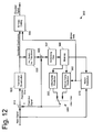
- the video encoder generally denoted by reference numeral 900, comprises a subtractor 910 for determining differences between a current block of a video image (input signal) and a prediction signal of the current block which is based on previously encoded blocks stored in memory 940.
- a transformation and quantization unit 920 transforms the resulting prediction error from the spatial domain to the frequency domain and quantizes the obtained transform coefficients.
- An entropy coding unit 990 entropy encodes the quantized transform coefficients.
- the input image is divided into macro blocks.
- the encoder 900 employs a Differential Pulse Code Modulation (DPCM) approach which only transmits differences between blocks of an input video sequence and their predictions based on previously encoded blocks ("the locally decoded image"). These differences are determined in subtractor 910, which receives the blocks to be encoded in order to subtract the prediction signal therefrom.
- DPCM Differential Pulse Code Modulation
- the locally decoded image is provided by a decoding unit incorporated into video encoder 900.
- the decoding unit performs the encoding steps in reverse manner.
- An inverse quantization and inverse transformation unit 930 dequantizes the quantized coefficients and applies an inverse transformation to the dequantized coefficients.
- adder 935 the decoded differences are added to the prediction signal to form the locally decoded image.
- a deblocking filter 937 reduces blocking artifacts in the decoded image.
- the type of prediction that is employed by video encoder 900 depends on whether the macro blocks are encoded in "Intra” or "inter” mode.
- “Intra” mode the video encoding standard H.264/AVC uses a prediction scheme based on already encoded macro blocks of the same image in order to predict subsequent macro blocks.
- “Inter” mode motion compensated prediction between corresponding blocks of several consecutive frames is employed.
- Intra-encoded images Only Intra-encoded images (I-type images) can be decoded without reference to any previously decoded image.
- the I-type images provide error resilience for the encoded video sequence. Further, entry points into bit streams of encoded data are provided by the I-type images in order to enable a random access, i.e. to access I-type images within the sequence of encoded video images.
- a switch between Intra-mode, i.e. a processing by Intra-frame prediction unit 950, and Inter-mode, i.e. a processing by motion compensated prediction unit 960, is controlled by Intra/Inter switch 980.
- a macro block is predicted from corresponding blocks of previous frames by employing motion compensation.
- the estimation is accomplished by a motion estimator unit 970, receiving the current input signal and the locally decoded image.
- Motion estimation yields two-dimensional motion vectors, representing a pixel displacement between the current block and the corresponding block in previous frames.
- a motion compensated prediction unit 960 Based on the estimated motion, a motion compensated prediction unit 960 provides a prediction signal.
- the differences between the current and the predicted signal are transformed into transform coefficients by transformation / quantization unit 920.
- an orthogonal transformation such as a two-dimensional Discrete Cosine transformation (DCT) or an integer version thereof is employed.
- the transform coefficients are quantized in order to reduce the amount of data that has to be encoded.
- the step of quantization is controlled by quantization tables that specify the precision and therewith the number of bits that are used to encode each frequency coefficient. Lower frequency components are usually more important for image quality than fine details so that more bits are spent for coding the low frequency components than for the higher ones.
- the two-dimensional array of transform coefficients has to be converted into a one-dimensional string to pass it to the entropy encoder. This conversion is done by scanning the array in a predetermined sequence. The thus obtained one-dimensional sequence of quantized transform coefficients is compressed to a series of number pairs called run levels. Finally, the run-level sequence is coded with binary code words of variable length (Variable Length Code, VLC). The code is optimized to assign shorter code words to most frequent run-level pairs occurring in typical video images. The resulting bitstream is multiplexed with the motion information and stored on a recording medium or transmitted to the decoder side.
- VLC Variable Length Code
- FIG. 13 A schematic block diagram, illustrating the configuration of the corresponding decoder, is shown in Fig. 13 .
- decoder 901 of Fig. 13 first the entropy encoding of transform coefficients and motion data is reversed in an entropy decoding unit 991. This step also involves an inverse scanning in order to convert the sequence of decoded transform coefficients into a two-dimensional block of data as it is required for the inverse transformation.
- the decoded block of transform coefficients is then submitted to an inverse quantizer and inverse transformer 921 and the decoded motion data is sent to a motion compensated prediction unit 960.
- the result of the inverse transformation contains prediction differences and is added by adder 935 to the prediction signal stemming from the motion compensated prediction unit 960 in Inter-mode or stemming from an Intra-frame prediction unit 950 in Intra-mode.
- the reconstructed image may be passed through a deblocking filter 937 and the decoded signal is stored in memory 940 to be applied to prediction units 950, 960.
- the present invention has been devised to overcome the above problems of image and video compression, in particular with respect to finely detailed images, and relates to an improved method and a corresponding apparatus for representing image and video data. It aims on improving subjective picture quality and can be combined with video coding schemes such as H.264/AVC.
- the inventive method is a combination of traditional image representation and subjective signal enhancement.
- an input signal is separated into two parts.
- one part is coded traditionally and the other part is represented by parameters.
- the traditionally coded part is reconstructed and the other one is employed to enhance the signal by applying a texture synthesis algorithm.
- FIG. 1 is a block diagram illustrating the basic idea of the present invention.
- the signal that is to be represented is fed to a signal separator 110, which is separating the input signal into two components.
- the first component is fed to a signal representation unit 140.
- the signal representation unit 140 is applying a deterministic signal representation method such as PCM (pulse code modulation), DPCM (differential pulse code modulation), and transform-based methods.
- PCM pulse code modulation
- DPCM differential pulse code modulation
- transform-based methods transform-based methods.
- Each of these representation methods aims at representing the signal so that an objective quality measure such as the MSE (means square error) of the represented signal relative to the original signal is optimized.
- MSE mean square error
- the second component is fed to a signal enhancement unit 120, wherein the signal is analyzed so as to compute texture parameters that represent a texture that is subjectively similar to a texture contained in the signal. Based on the computed texture parameters, the signal enhancement unit 120 synthesizes a texture and outputs a signal based on the synthesized texture.
- the synthesized texture is not a faithful representation of the second component signal in terms of an objective quality measure such as MSE. Nevertheless, the synthesized texture may provide a subjectively satisfying replacement for the original signal content in the sense that it contains the relevant information about its texture, e.g., grass, gravel, etc., whereas irrelevant details such as form and position of individual blades of grass or pebble stones are neglected.
- Both the texture signal and the representation of the first component signal is jointly fed to a signal composition unit 150, wherein an output signal is generated that contains the synthesized texture signal and the representation of the first component signal.
- the first component consists of the lower frequencies of the input signal, whereas the complementary second component contains the remaining higher frequencies.
- those signal parts that are more important for the human visual system are faithfully represented in a traditional manner and signal parts, where the human visual system is less sensitive, i.e., the higher frequency components, are synthesized using texture synthesis.
- the advantages of both approaches can be combined and the subjective picture quality, especially the authenticity of textures, can be improved significantly.
- the signal separator 110 performs a sub-band decomposition of the input signal. Therefore, the signal separator 110 may comprise a plurality of filters, especially low-pass, band-pass, and high-pass filters, that separate the input signal into the lower and the higher frequency components. Specifically, the signal separator 110 may perform a wavelet transformation in order to separate the input signal into its sub-bands. Alternatively, a Fourier transformation, especially a discrete cosine transformation may be performed. However, other sub-band approaches are also possible, such as approaches based on steerable pyramids.
- the signal enhancement unit 130 may apply any texture analysis and synthesis method known in the art. For instance, a parametric texture model based on joint statistics of complex wavelet transforms may be applied, as illustrated by the flowchart in Fig. 2 .
- a steerable pyramid is constructed in step B10 by recursively decomposing the input signal to the signal enhancement unit 130 into a set of oriented sub-bands and a lowpass residual band.
- Statistical texture parameters are then computed in steps B20-B40 using this decomposition.
- marginal statistics descriptors such as variance, skewness and kurtosis as well as minimum and maximum values of the image pixels are computed at each level of the pyramid, including parameters that describe the marginal statistics of the entire image.
- autocorrelations and various cross-correlations are computed at and inbetween the levels of the pyramid.
- a white noise image is generated in step B50 and decomposed into oriented sub-bands by the steerable pyramid approach in step B60 in accordance with the decomposition performed in step B10.
- Each sub-band of the white noise image is further tweaked in step B70 so as to meet the statistical constraints described by the computed texture parameters.
- the pyramid is collapsed in step B80 and tweaked in step B90 so that the marginal statistics of its pixel data meets statistical parameters computed in step B20 for the entire image.
- Steps B60 - B90 may be iterated, i.e., the generated texture may be employed as a starting point for the decomposition and tweaking process instead of the white noise image, for a predetermined number of iterations or until the synthesized texture has become sufficiently stable.
- the operation of the signal enhancement unit 120 has been exemplified by means of a particular parametric texture model, the present invention is not restricted in this respect. Instead, any parametric texture model or even non-parametric texture models, such as sampling-based models, may be employed.
- Signal composition unit 150 is basically performing the inverse operation of the signal separator 110.
- the output signals of the signal enhancement unit 120 and the signal representation unit 140 may simply be added in order to generate the desired output signal.
- more complex operations such as collapsing a steerable pyramid or an inverse wavelet-transformation, may be needed depending on the mechanism that has been employed for separating the input signal into two components.
- Figure 3 illustrates an alternative configuration of the block diagram of Fig. 1 , wherein the signal enhancement unit 120 and the signal composition unit 150 are merged into a signal enhancement and composition unit 130, which also receives an additional copy of the original input signal.
- the signal enhancement and composition unit 130 may also receive a copy of the first component instead of the original input signal.
- the texture parameters may also be computed by taking the original input signal into account.
- the computed texture parameters may also comprise cross-correlations between the first and the second component, which would not be possible otherwise. These cross-correlations may describe the spatial information for the texture that is to be synthesized. In other words, for a quasi periodic texture such as a brick wall or a woven fabric, cross-correlations between the low-frequency and the high frequency component may contain the phase information needed for correctly merging the synthesized texture and the reconstructed low-frequency component.
- the synthesis of the texture may also be based on the reconstructed first component signal so as to take the information contained in the low-pass component into account.
- the texture may be synthesized based on texture parameters that describe a statistical relation between the first and the second signal component, such as the cross-correlations mentioned above.
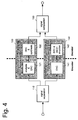
- Figure 4 illustrates a particular application of the present invention to image and video coding.
- the image or video signal to be encoded is fed to the signal separator 110, where it is split into two separate sub-bands as described above.
- the two sub-band components are encoded independently of each other.
- the low-frequency component is fed to a conventional image or video encoder 141 and is encoded into a first bitstream.
- the high-frequency component is fed to a texture analysis and encoding unit 121.
- the texture analysis and encoding unit 121 is computing representative texture parameters as describe in connection with Fig. 1 .
- the thus computed texture parameters are then encoded into a second bitstream.
- texture parameters For encoding texture parameters a method similar to the encoding of transform coefficients, as described above in connection with Fig. 12 , may be employed.
- texture parameters are converted into a one-dimensional data string and passed to an entropy coder in order to be encoded by a variable-length code, such as a Huffman code.
- the texture parameters may also be quantized in analogy to the transform coefficients in order to reduce the amount of data to be encoded.
- the first and the second bitstream may be multiplexed into a single bitstream which is then output by the encoder constituted by the signal separator 110, the encoder 141, and the texture analysis and encoding unit 121.
- the bitstream(s) output by the encoder may be stored to a recording medium or transmitted over a transmission channel.
- the received bitstream may be de-multiplexed into the first bitstream representing the low-frequency component and the second bitstream containing the texture parameters.
- the first and the second bitstream are then received by a decoder and reconstruction unit 142 and a decoder and synthesizer unit 122, respectively.
- the decoder and reconstruction unit 142 is decoding the first bitstream and reconstructing the low-frequency component of the original input signal.
- the decoder and synthesizer unit 122 is decoding the texture parameters contained in the second bitstream and is synthesizing, based on the decoded texture parameters, a texture signal that mimics the high-frequency component of the original input signal.
- the reconstructed low-frequency component and the synthesized texture signal are fed to a signal composition unit 150 in order to be merged into the decoder's output signal.
- input image/video data can be compressed in a highly efficient manner since subjectively irrelevant details contained in the irregular pattern of the high-frequency component are replaced by a synthesized texture, which is fully determined by a few texture parameters only.
- a synthesized texture which is fully determined by a few texture parameters only.
- the present invention can achieve a superior subjective image quality, because the synthesized texture is sharper and more detail rich than what can be achieved by conventional video compression methods at comparable compression rates. Most importantly, the synthesized texture is free of any disturbing compression artifacts.
- the present invention can represent texture in a more natural and authentic manner than conventional video compression techniques based on texture synthesis, because the low-frequency component is faithfully represented rather than synthesized.
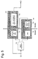
- Figure 5 illustrates an alternative configuration of the image/video coder shown in Fig. 4 .
- the decoder and synthesizer unit 122 and the signal composition unit 150 are merged into a single decoder, synthesizer, and signal composition unit 132.
- the texture analysis and encoding unit 131 receives an additional copy of the original input signal.
- the texture parameters may also be computed by taking the original input signal into account and the synthesis of the texture on the decoder side may in addition be based on the reconstructed first component signal so as to also take information contained in the low-pass component into account.
- the reconstructed first component signal output by the reconstruction unit 142 may be used in the texture synthesis algorithm in order to get an output image that is visually similar to the original one.
- the encoder may compute texture parameters that comprise cross-correlations between the first and the second component, which may then be used by the decoder to get the spatial information, i.e. the phase, of a texture right.
- This may be particularly important in case of images that are further divided in the spatial domain into separately represented regions. Disturbing artifacts like visible seams at the regions' borders can only be prevented if the textures for each region are synthesized with the correct phase relative to each other.
- this is achieved by fixing the phase of the synthesized texture to features of the low-frequency component, for instance by employing the above mentioned cross-correlations between the high and the low-frequency component.
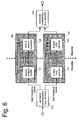
- Figure 6 illustrates a specific example of applying the present invention to video coding.
- the configuration shown in Fig. 6 is similar to that of Fig. 4 , wherein like parts are denoted by like reference numerals, a detailed explanation of which will be omitted.
- the signal separator 110 splits the input video signal into a low-frequency and a high-frequency component by means of, for instance, a wavelet-based sub-band decomposition.
- the low-frequency component which is particularly important for the human visual system, is encoded into the first bitstream by a conventional video encoding method such as H.264/AVC.
- the high-frequency component which is less important for the human visual system, is analyzed and the resulting texture parameters are encoded as described above in connection with Fig. 4 .
- the first bitstream is decoded in accordance with the corresponding conventional H.264/AVC decoder.
- the second bitstream is decoded as described above in connection with Fig. 4 .
- the sub-band composition unit receives both the reconstructed low-frequency component and the synthesized high-frequency component so as to compose the final output signal, e.g., by means of a wavelet-based sub-band composition method.
- a new set of texture parameters may be computed and encoded for each frame of the input video signal.
- some or all of the texture parameters may be transmitted to the decoder only once for several frames, so that the texture is synthesized based on at least partially identical sets of texture parameters for a plurality of frames. This is particularly useful to further reduce the amount of data that has to be transmitted or recorded in cases where intrinsic texture properties do not change from frame to frame. It is to be noted that texture movement can still be represented if cross-correlations with the low-frequency component are employed.
- Figure 7 illustrates an alternative configuration of the video coder shown in Fig. 6 .
- the sub-band composition unit 150 and the decoder and synthesizer unit 122 are merged into a single decoder, synthesizer, and sub-band composition unit 132.
- the texture analysis and encoding unit 131 receives an additional copy of the original input signal. In this configuration, the same advantages can be achieved as described in connection with Fig. 5 .
- the set of texture parameters may also comprise cross-correlations between the high and the low-frequency component. These cross-correlations can then be employed at the decoder side to fix the spatial information ("phase") of the synthesized texture. Due to fixing the "phase" of the synthesized texture to features of the low-frequency component by means of cross-correlation, even time-varying textures can be represented. Moving objects, for instance, will carry their texture along themselves as the texture is fixed to the object's features represented in the low-frequency component.
- Figure 8 illustrates another specific example of applying the present invention to video coding.
- the configuration shown in Fig. 8 is similar to that of Fig. 6 , wherein like parts are denoted by like reference numerals, a detailed explanation of which will be omitted.
- the configuration shown in Fig. 8 differs from the configuration of Fig. 6 in that the signal separator 110 is based on steerable pyramids, i.e., a recursive multiscale sub-band decomposition scheme.
- the input signal is separated into a low-pass image L 0 and a high-pass residual image H 0 .
- the low-pass image is further decomposed into N oriented band-pass images B 0 0 ... B N - 1 0 and another low-pass image L 1 , which is downsampled by a factor of 2. This step may be repeated recursively.
- the low-pass residual image at the coarsest scale L M- 1 is coded by a conventional H264/AVC encoder 141. Both the H264/AVC bitstream and the bitstream of texture parameters is transmitted to the decoder.
- the texture parameters are decoded and the sub-bands at the finer scales are substituted by a texture synthesis algorithm.
- the H264/AVC bitstream is decoded by a H264/AVC decoder in order to obtain the low-pass residual image.
- the entire pyramid is collapsed in the sub-band composition unit 150 in order to generate the decoded output signal.
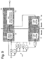
- Figure 9 illustrates an alternative configuration of the video coder shown in Fig. 8 .
- the sub-band composition unit 150 and the decoder and synthesizer unit 122 are merged into a single decoder, synthesizer, and sub-band composition unit 132.
- the texture analysis and encoding unit 131 receives an additional copy of the original input signal. In this configuration, the same advantages can be achieved as described in connection with Figs. 5 and 7 .
- a decomposition based on one scale and four oriented band-pass filters is employed.
- the low-pass residual image is handled by the conventional encoder, whereas the complementary image component is represented by texture synthesis.
- signal separation can be seen as a classical frequency band separation in connection with an anti-aliasing filter.
- the steerable pyramid decomposition will only become relevant for texture synthesis in accordance with the method describe above in connection with Fig. 2 .
- the original input image will be further decomposed at an additional scale.
- the band-pass components on the first scale and the high-pass residual correspond to the statistical signal component.
- the band-pass components on the second scale and the low-pass residual correspond to the deterministic signal component.
- FIG. 10 is a block diagram of the decoder, synthesizer, and sub-band composition unit 132 in accordance with an embodiment of the present invention.
- the bitstream of encoded texture parameters is fed to a decoder 270, which outputs the decoded texture parameters required for texture synthesis.
- texture synthesis starts from a white noise image generated by white noise generator 205.
- the white noise image is decomposed into a steerable pyramid by decomposition unit 210.
- the low-frequency sub-bands B 0 M - 1 , ... , B N - 1 M - 1 and the low-pass residual image L M-1 output by decomposition unit 210 are replaced by the corresponding components of the decoded low-pass component.
- the replacement components are generated by filter bank 280 from the output of decoder 142. It is to be noted that this replacement actually corresponds to the sub-band composition performed by sub-band composition unit 150 in the first configuration of the present invention.
- the pixel data distribution of the high-frequency sub-bands is then tweaked so as to meet the statistical constraints described by the texture parameters.
- the high frequency residual H 0 is transformed so as to meet a variance constraint by unit 230, whereas sub-band statistics including cross-correlations, skewness, and kurtosis are imposed on the intermediate frequency sub-bands B 0 0 , ... , B N - 1 0 from decomposition unit 210.
- the decoded low frequency components B 0 M - 1 , ... , B N - 1 M - 1 L M -1 from decoder 142 are not altered by sub-band statistics unit 240.
- This unit further collapses the intermediate and the low frequency sub-bands of the steerable pyramid and feeds the thus reconstructed signal to unit 250 in order to impose constraints regarding the autocorrelation, skewness, and kurtosis.
- Adder 260 is performing the last step of collapsing the steerable pyramid by adding the outputs of units 230 and 250.
- Statistics unit 220 imposes statistical constraints regarding the entire image so as to provide finally the decoder's output signal. The entire synthesis process may be iterated via switch 206.
- the present invention has been exemplified in terms of block diagrams and encoder/decoder apparatuses. However, this invention may also be implemented as a method for encoding and decoding image/video data or as a computer program product with program code stored on a computer readable medium.
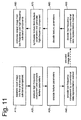
- FIG 11 is a flow chart illustrating a method for image and video coding in accordance with an embodiment of the present invention.
- step A10 an input image is separated into a first and a second sub-band component.
- the high-frequency component is analyzed in step A20 so as to compute representative texture parameters, which are then encoded in step A30.
- the representative texture parameters may also be computed by taking the original input signal into account so as to compute texture parameters that describe a relation between the first and the second sub-band component, such as cross-correlations.
- the low-frequency component is encoded by a conventional data representation method in step A40. At this point the entire input image is encoded and the encoded image data may be stored to a recording medium or transmitted via a communications channel.
- the low-frequency component Upon decoding the encoded image data, the low-frequency component is decoded by the conventional data representation method in step A50.
- the texture parameters are decoded in step A60 and texture is synthesized from the decoded texture parameters so as to generate a high-frequency sub-band component in step A70.
- the texture may also be synthesized by taking the decoded low-frequency sub-band component into account so as to fix the spatial information of the synthesized texture.
- the output image is composed from the low-frequency and the high-frequency sub-band components.
- the present invention relates to a hybrid method for texture representation and, in particular, to image and video data compression based on this method and corresponding encoder and decoder apparatuses.
- An input signal is separated in the frequency domain into two sub-band components.
- the low-frequency component is encoded faithfully by means of a conventional image/video encoder.
- the high-frequency component is analyzed so as to compute representative texture parameters. Instead of faithfully encoding the high-frequency component, only the computed texture parameters are stored or transmitted.
- the low-frequency component is reconstructed, whereas the high-frequency component is replaced by a similar-looking texture that has been synthesized in accordance with the texture parameters. Both the reconstructed low-frequency component and the synthesized high-frequency component are then merged in order to generate the output signal.
Landscapes
- Engineering & Computer Science (AREA)
- Multimedia (AREA)
- Signal Processing (AREA)
- Physics & Mathematics (AREA)
- Discrete Mathematics (AREA)
- General Physics & Mathematics (AREA)
- Compression Or Coding Systems Of Tv Signals (AREA)
Priority Applications (5)
| Application Number | Priority Date | Filing Date | Title |
|---|---|---|---|
| EP06024537A EP1926321A1 (de) | 2006-11-27 | 2006-11-27 | Hybride Strukturdarstellung |
| EP07832547A EP2088785A4 (de) | 2006-11-27 | 2007-11-27 | Bildcodierungsvorrichtung und bilddecodierungsteil |
| PCT/JP2007/072822 WO2008066025A1 (fr) | 2006-11-27 | 2007-11-27 | Appareil de codage d'image et partie de décodage d'image |
| US12/513,735 US20100046845A1 (en) | 2006-11-27 | 2007-11-27 | Image coding apparatus and image decoding apparatus |
| JP2008546992A JPWO2008066025A1 (ja) | 2006-11-27 | 2007-11-27 | 画像符号化装置及び画像復号化装置 |
Applications Claiming Priority (1)
| Application Number | Priority Date | Filing Date | Title |
|---|---|---|---|
| EP06024537A EP1926321A1 (de) | 2006-11-27 | 2006-11-27 | Hybride Strukturdarstellung |
Publications (1)
| Publication Number | Publication Date |
|---|---|
| EP1926321A1 true EP1926321A1 (de) | 2008-05-28 |
Family
ID=37898662
Family Applications (2)
| Application Number | Title | Priority Date | Filing Date |
|---|---|---|---|
| EP06024537A Withdrawn EP1926321A1 (de) | 2006-11-27 | 2006-11-27 | Hybride Strukturdarstellung |
| EP07832547A Withdrawn EP2088785A4 (de) | 2006-11-27 | 2007-11-27 | Bildcodierungsvorrichtung und bilddecodierungsteil |
Family Applications After (1)
| Application Number | Title | Priority Date | Filing Date |
|---|---|---|---|
| EP07832547A Withdrawn EP2088785A4 (de) | 2006-11-27 | 2007-11-27 | Bildcodierungsvorrichtung und bilddecodierungsteil |
Country Status (4)
| Country | Link |
|---|---|
| US (1) | US20100046845A1 (de) |
| EP (2) | EP1926321A1 (de) |
| JP (1) | JPWO2008066025A1 (de) |
| WO (1) | WO2008066025A1 (de) |
Cited By (3)
| Publication number | Priority date | Publication date | Assignee | Title |
|---|---|---|---|---|
| WO2013166439A1 (en) * | 2012-05-04 | 2013-11-07 | Setem Technologies, Llc | Systems and methods for source signal separation |
| US9728182B2 (en) | 2013-03-15 | 2017-08-08 | Setem Technologies, Inc. | Method and system for generating advanced feature discrimination vectors for use in speech recognition |
| US10497381B2 (en) | 2012-05-04 | 2019-12-03 | Xmos Inc. | Methods and systems for improved measurement, entity and parameter estimation, and path propagation effect measurement and mitigation in source signal separation |
Families Citing this family (24)
| Publication number | Priority date | Publication date | Assignee | Title |
|---|---|---|---|---|
| JP4659005B2 (ja) * | 2007-08-17 | 2011-03-30 | 日本電信電話株式会社 | テクスチャ合成に基づく動画像符号化方法,復号方法,符号化装置,復号装置およびそれらのプログラムとその記録媒体 |
| KR20110020242A (ko) * | 2008-06-05 | 2011-03-02 | 톰슨 라이센싱 | 텍스처 합성을 이용하는 이미지 코딩 방법 |
| WO2011090352A2 (ko) * | 2010-01-22 | 2011-07-28 | 삼성전자주식회사 | 영역 기반의 부호화/복호화 장치 및 방법 |
| WO2011090790A1 (en) | 2010-01-22 | 2011-07-28 | Thomson Licensing | Methods and apparatus for sampling -based super resolution vido encoding and decoding |
| CN102726044B (zh) | 2010-01-22 | 2016-08-10 | 汤姆逊许可证公司 | 使用基于示例的超分辨率的用于视频压缩的数据剪切 |
| JP5351093B2 (ja) * | 2010-06-01 | 2013-11-27 | 日本電信電話株式会社 | 画像符号化方法,画像符号化装置および画像符号化プログラム |
| JP5351094B2 (ja) * | 2010-06-01 | 2013-11-27 | 日本電信電話株式会社 | 画像符号化方法,画像符号化装置および画像符号化プログラム |
| US9544598B2 (en) | 2010-09-10 | 2017-01-10 | Thomson Licensing | Methods and apparatus for pruning decision optimization in example-based data pruning compression |
| WO2012033970A1 (en) | 2010-09-10 | 2012-03-15 | Thomson Licensing | Encoding of a picture in a video sequence by example - based data pruning using intra- frame patch similarity |
| CN103210648B (zh) * | 2010-09-10 | 2017-06-09 | 汤姆逊许可公司 | 使用基于块的混合分辨率数据修剪的视频解码 |
| JP5700666B2 (ja) * | 2011-06-27 | 2015-04-15 | 日本電信電話株式会社 | 画像復号装置、画像復号方法及び画像復号プログラム |
| EP2920962A4 (de) * | 2012-11-13 | 2016-07-20 | Intel Corp | Inhaltsadaptive transformationscodierung für videos der nächsten generation |
| US9883198B2 (en) * | 2012-11-13 | 2018-01-30 | Intel Corporation | Video codec architecture for next generation video |
| CN104919517B (zh) * | 2013-01-21 | 2016-10-26 | 夏普株式会社 | 显示装置和显示装置的数据处理方法 |
| WO2014120369A1 (en) | 2013-01-30 | 2014-08-07 | Intel Corporation | Content adaptive partitioning for prediction and coding for next generation video |
| US9241163B2 (en) * | 2013-03-15 | 2016-01-19 | Intersil Americas LLC | VC-2 decoding using parallel decoding paths |
| US9842410B2 (en) * | 2015-06-18 | 2017-12-12 | Samsung Electronics Co., Ltd. | Image compression and decompression with noise separation |
| JP6883219B2 (ja) | 2016-04-22 | 2021-06-09 | ソニーグループ株式会社 | 符号化装置及び符号化方法、並びに、システム |
| US10791343B2 (en) * | 2018-03-13 | 2020-09-29 | Google Llc | Mixed noise and fine texture synthesis in lossy image compression |
| US10419738B1 (en) | 2018-06-14 | 2019-09-17 | Telefonaktiebolaget Lm Ericsson (Publ) | System and method for providing 360° immersive video based on gaze vector information |
| US10567780B2 (en) | 2018-06-14 | 2020-02-18 | Telefonaktiebolaget Lm Ericsson (Publ) | System and method for encoding 360° immersive video |
| US10623736B2 (en) * | 2018-06-14 | 2020-04-14 | Telefonaktiebolaget Lm Ericsson (Publ) | Tile selection and bandwidth optimization for providing 360° immersive video |
| US10841662B2 (en) | 2018-07-27 | 2020-11-17 | Telefonaktiebolaget Lm Ericsson (Publ) | System and method for inserting advertisement content in 360° immersive video |
| US10757389B2 (en) | 2018-10-01 | 2020-08-25 | Telefonaktiebolaget Lm Ericsson (Publ) | Client optimization for providing quality control in 360° immersive video during pause |
Citations (1)
| Publication number | Priority date | Publication date | Assignee | Title |
|---|---|---|---|---|
| WO1997016027A2 (en) * | 1995-10-24 | 1997-05-01 | Line Imaging Systems L.L.C. | Ultrasound video subband coding system and method |
Family Cites Families (6)
| Publication number | Priority date | Publication date | Assignee | Title |
|---|---|---|---|---|
| US6141446A (en) * | 1994-09-21 | 2000-10-31 | Ricoh Company, Ltd. | Compression and decompression system with reversible wavelets and lossy reconstruction |
| US5872867A (en) * | 1995-08-04 | 1999-02-16 | Sarnoff Corporation | Method and apparatus for generating image textures |
| US6977659B2 (en) * | 2001-10-11 | 2005-12-20 | At & T Corp. | Texture replacement in video sequences and images |
| KR100716210B1 (ko) * | 2005-09-20 | 2007-05-10 | 웅진코웨이주식회사 | 폴리아미드 역삼투 복합막 제조방법 및 이로부터 제조된폴리아미드 역삼투 복합막 |
| JP2007184800A (ja) * | 2006-01-10 | 2007-07-19 | Hitachi Ltd | 画像符号化装置、画像復号化装置、画像符号化方法及び画像復号化方法 |
| US7734107B2 (en) * | 2006-02-24 | 2010-06-08 | Sony Corporation | System and method for performing wavelet-based texture feature extraction and classification |
-
2006
- 2006-11-27 EP EP06024537A patent/EP1926321A1/de not_active Withdrawn
-
2007
- 2007-11-27 WO PCT/JP2007/072822 patent/WO2008066025A1/ja active Application Filing
- 2007-11-27 US US12/513,735 patent/US20100046845A1/en not_active Abandoned
- 2007-11-27 JP JP2008546992A patent/JPWO2008066025A1/ja not_active Withdrawn
- 2007-11-27 EP EP07832547A patent/EP2088785A4/de not_active Withdrawn
Patent Citations (1)
| Publication number | Priority date | Publication date | Assignee | Title |
|---|---|---|---|---|
| WO1997016027A2 (en) * | 1995-10-24 | 1997-05-01 | Line Imaging Systems L.L.C. | Ultrasound video subband coding system and method |
Non-Patent Citations (2)
| Title |
|---|
| MARCUS J NADENAU ET AL: "Visually Improved Image Compression by Combining a Conventional Wavelet-Codec With Texture Modeling", IEEE TRANSACTIONS ON IMAGE PROCESSING, IEEE SERVICE CENTER, PISCATAWAY, NJ, US, vol. 11, no. 11, November 2002 (2002-11-01), XP011074325, ISSN: 1057-7149 * |
| NDJIKI-NYA P ET AL: "Improved H.264/AVC coding using texture analysis and synthesis", PROCEEDINGS 2003 INTERNATIONAL CONFERENCE ON IMAGE PROCESSING. ICIP-2003. BARCELONA, SPAIN, SEPT. 14 - 17, 2003, INTERNATIONAL CONFERENCE ON IMAGE PROCESSING, NEW YORK, NY : IEEE, US, vol. VOL. 2 OF 3, 14 September 2003 (2003-09-14), pages 849 - 852, XP010669967, ISBN: 0-7803-7750-8 * |
Cited By (9)
| Publication number | Priority date | Publication date | Assignee | Title |
|---|---|---|---|---|
| WO2013166439A1 (en) * | 2012-05-04 | 2013-11-07 | Setem Technologies, Llc | Systems and methods for source signal separation |
| US9443535B2 (en) | 2012-05-04 | 2016-09-13 | Kaonyx Labs LLC | Systems and methods for source signal separation |
| US9495975B2 (en) | 2012-05-04 | 2016-11-15 | Kaonyx Labs LLC | Systems and methods for source signal separation |
| US10497381B2 (en) | 2012-05-04 | 2019-12-03 | Xmos Inc. | Methods and systems for improved measurement, entity and parameter estimation, and path propagation effect measurement and mitigation in source signal separation |
| US10957336B2 (en) | 2012-05-04 | 2021-03-23 | Xmos Inc. | Systems and methods for source signal separation |
| US10978088B2 (en) | 2012-05-04 | 2021-04-13 | Xmos Inc. | Methods and systems for improved measurement, entity and parameter estimation, and path propagation effect measurement and mitigation in source signal separation |
| US9728182B2 (en) | 2013-03-15 | 2017-08-08 | Setem Technologies, Inc. | Method and system for generating advanced feature discrimination vectors for use in speech recognition |
| US10410623B2 (en) | 2013-03-15 | 2019-09-10 | Xmos Inc. | Method and system for generating advanced feature discrimination vectors for use in speech recognition |
| US11056097B2 (en) | 2013-03-15 | 2021-07-06 | Xmos Inc. | Method and system for generating advanced feature discrimination vectors for use in speech recognition |
Also Published As
| Publication number | Publication date |
|---|---|
| EP2088785A1 (de) | 2009-08-12 |
| EP2088785A4 (de) | 2011-06-08 |
| WO2008066025A1 (fr) | 2008-06-05 |
| US20100046845A1 (en) | 2010-02-25 |
| JPWO2008066025A1 (ja) | 2010-03-04 |
Similar Documents
| Publication | Publication Date | Title |
|---|---|---|
| EP1926321A1 (de) | Hybride Strukturdarstellung | |
| RU2503137C2 (ru) | Способ и устройство для высокомасштабируемого внутрикадрового видеокодирования | |
| EP2207358A1 (de) | Videodekodierungsverfahren und videokodierungsverfahren | |
| US20020110280A1 (en) | Adaptive transforms | |
| MX2008012863A (es) | Metodo y aparato de codificacion de video que soporta analisis sintactico independiente. | |
| Nister et al. | Lossless region of interest with a naturally progressive still image coding algorithm | |
| Cruz et al. | Region of Interest coding in JPEG2000 for interactive client/server applications | |
| Rehna et al. | Wavelet based image coding schemes: A recent survey | |
| JP2006304329A (ja) | 符号化方法及び復号化方法及び符号化装置及び復号化装置 | |
| Wei | An introduction to image compression | |
| KR20000059799A (ko) | 웨이브릿 부호화를 이용한 움직임 보상 부호화 장치 및 방법 | |
| US20220248057A1 (en) | Encoder and method of encoding a sequence of frames | |
| Taubman et al. | Highly scalable video compression with scalable motion coding | |
| US8331708B2 (en) | Method and apparatus for a multidimensional discrete multiwavelet transform | |
| KR100679027B1 (ko) | Dc 성분의 손실 없이 영상을 코딩하는 방법 및 장치 | |
| EP1841235A1 (de) | Videokompression mittels adaptiver 2D-Transformation in räumliche und zeitliche Richtung | |
| JPH08294119A (ja) | 画像符号化/復号化装置 | |
| Babel et al. | Interleaved S+ P pyramidal decomposition with refined prediction model | |
| Baligar et al. | Low complexity, and high fidelity image compression using fixed threshold method | |
| Singh et al. | JPEG2000: A review and its performance comparison with JPEG | |
| KR100349518B1 (ko) | 인간 시각 시스템의 특성을 반영한 퍼지 논리를 적용한이산 웨이브렛 변환을 이용한 영상 압축 방법 및 장치 | |
| JP3660548B2 (ja) | 画像符号化方法及び画像復号方法、画像符号化装置及び画像復号装置、並びにそれらのプログラムを記憶した媒体 | |
| Hu et al. | Motion differential set partition coding for image sequence and video compression | |
| Morris et al. | Intra-frame wavelet video coding | |
| KR20070034918A (ko) | Fgs 계층의 비디오 데이터를 엔트로피 부호화 및복호화하는 방법 및 장치 |
Legal Events
| Date | Code | Title | Description |
|---|---|---|---|
| PUAI | Public reference made under article 153(3) epc to a published international application that has entered the european phase |
Free format text: ORIGINAL CODE: 0009012 |
|
| AK | Designated contracting states |
Kind code of ref document: A1 Designated state(s): AT BE BG CH CY CZ DE DK EE ES FI FR GB GR HU IE IS IT LI LT LU LV MC NL PL PT RO SE SI SK TR |
|
| AX | Request for extension of the european patent |
Extension state: AL BA HR MK RS |
|
| RAP1 | Party data changed (applicant data changed or rights of an application transferred) |
Owner name: PANASONIC CORPORATION |
|
| AKX | Designation fees paid | ||
| STAA | Information on the status of an ep patent application or granted ep patent |
Free format text: STATUS: THE APPLICATION IS DEEMED TO BE WITHDRAWN |
|
| 18D | Application deemed to be withdrawn |
Effective date: 20081201 |
|
| REG | Reference to a national code |
Ref country code: DE Ref legal event code: 8566 |