EP1925947A1 - In-vehicle radar apparatus and method for manufacturing the same - Google Patents
In-vehicle radar apparatus and method for manufacturing the same Download PDFInfo
- Publication number
- EP1925947A1 EP1925947A1 EP07121405A EP07121405A EP1925947A1 EP 1925947 A1 EP1925947 A1 EP 1925947A1 EP 07121405 A EP07121405 A EP 07121405A EP 07121405 A EP07121405 A EP 07121405A EP 1925947 A1 EP1925947 A1 EP 1925947A1
- Authority
- EP
- European Patent Office
- Prior art keywords
- casing
- reference plane
- reference unit
- unit
- radar apparatus
- Prior art date
- Legal status (The legal status is an assumption and is not a legal conclusion. Google has not performed a legal analysis and makes no representation as to the accuracy of the status listed.)
- Ceased
Links
- 238000000034 method Methods 0.000 title claims description 12
- 238000004519 manufacturing process Methods 0.000 title claims description 5
- 238000012423 maintenance Methods 0.000 description 1
Images





Classifications
-
- G—PHYSICS
- G01—MEASURING; TESTING
- G01S—RADIO DIRECTION-FINDING; RADIO NAVIGATION; DETERMINING DISTANCE OR VELOCITY BY USE OF RADIO WAVES; LOCATING OR PRESENCE-DETECTING BY USE OF THE REFLECTION OR RERADIATION OF RADIO WAVES; ANALOGOUS ARRANGEMENTS USING OTHER WAVES
- G01S7/00—Details of systems according to groups G01S13/00, G01S15/00, G01S17/00
- G01S7/02—Details of systems according to groups G01S13/00, G01S15/00, G01S17/00 of systems according to group G01S13/00
- G01S7/40—Means for monitoring or calibrating
- G01S7/4004—Means for monitoring or calibrating of parts of a radar system
- G01S7/4026—Antenna boresight
- G01S7/403—Antenna boresight in azimuth, i.e. in the horizontal plane
-
- G—PHYSICS
- G01—MEASURING; TESTING
- G01S—RADIO DIRECTION-FINDING; RADIO NAVIGATION; DETERMINING DISTANCE OR VELOCITY BY USE OF RADIO WAVES; LOCATING OR PRESENCE-DETECTING BY USE OF THE REFLECTION OR RERADIATION OF RADIO WAVES; ANALOGOUS ARRANGEMENTS USING OTHER WAVES
- G01S7/00—Details of systems according to groups G01S13/00, G01S15/00, G01S17/00
- G01S7/02—Details of systems according to groups G01S13/00, G01S15/00, G01S17/00 of systems according to group G01S13/00
- G01S7/40—Means for monitoring or calibrating
- G01S7/4004—Means for monitoring or calibrating of parts of a radar system
- G01S7/4026—Antenna boresight
-
- G—PHYSICS
- G01—MEASURING; TESTING
- G01S—RADIO DIRECTION-FINDING; RADIO NAVIGATION; DETERMINING DISTANCE OR VELOCITY BY USE OF RADIO WAVES; LOCATING OR PRESENCE-DETECTING BY USE OF THE REFLECTION OR RERADIATION OF RADIO WAVES; ANALOGOUS ARRANGEMENTS USING OTHER WAVES
- G01S7/00—Details of systems according to groups G01S13/00, G01S15/00, G01S17/00
- G01S7/02—Details of systems according to groups G01S13/00, G01S15/00, G01S17/00 of systems according to group G01S13/00
- G01S7/40—Means for monitoring or calibrating
- G01S7/4004—Means for monitoring or calibrating of parts of a radar system
- G01S7/4026—Antenna boresight
- G01S7/4034—Antenna boresight in elevation, i.e. in the vertical plane
-
- G—PHYSICS
- G01—MEASURING; TESTING
- G01S—RADIO DIRECTION-FINDING; RADIO NAVIGATION; DETERMINING DISTANCE OR VELOCITY BY USE OF RADIO WAVES; LOCATING OR PRESENCE-DETECTING BY USE OF THE REFLECTION OR RERADIATION OF RADIO WAVES; ANALOGOUS ARRANGEMENTS USING OTHER WAVES
- G01S7/00—Details of systems according to groups G01S13/00, G01S15/00, G01S17/00
- G01S7/48—Details of systems according to groups G01S13/00, G01S15/00, G01S17/00 of systems according to group G01S17/00
- G01S7/497—Means for monitoring or calibrating
- G01S7/4972—Alignment of sensor
-
- G—PHYSICS
- G01—MEASURING; TESTING
- G01S—RADIO DIRECTION-FINDING; RADIO NAVIGATION; DETERMINING DISTANCE OR VELOCITY BY USE OF RADIO WAVES; LOCATING OR PRESENCE-DETECTING BY USE OF THE REFLECTION OR RERADIATION OF RADIO WAVES; ANALOGOUS ARRANGEMENTS USING OTHER WAVES
- G01S7/00—Details of systems according to groups G01S13/00, G01S15/00, G01S17/00
- G01S7/52—Details of systems according to groups G01S13/00, G01S15/00, G01S17/00 of systems according to group G01S15/00
- G01S7/52004—Means for monitoring or calibrating
Definitions
- the present invention relates to in-vehicle radar apparatuses and methods for manufacturing the apparatuses, and more particularly, to an in-vehicle radar apparatus having a reference plane for adjusting a beam axis and a method for manufacturing the same.
- An in-vehicle radar apparatus has been developed in order to secure vehicle travel safety.
- the in-vehicle radar apparatus emits a beam of radio waves in the millimeter wavelength range or laser, and detects a target such as another vehicle from the beam reflected by the target. It is desired to control the beam emission angle (beam axis) with respect to the vehicle for improvements in precision.
- poor accuracy in attachment of an antennal to a casing may cause the angle of the beam axis with respect to the casing to deviate from the designed value.
- the beam axis cannot be controlled precisely when the in-vehicle radar apparatus is attached to the vehicle with the casing being used as a reference plan.
- Japanese Patent Application Publication No. 2004-347512 discloses a reference plane aligned with the beam axis at the time of shipment of the in-vehicle radar apparatus. The beam axis is aligned with the reference plane when the radar apparatus is attached to the vehicle.
- the beam axis with respect to the casing deviates from the target value by ⁇ 2° to ⁇ 3°, while the beam axis with respect to the vehicle is desired to be aligned within ⁇ 0.3°.
- the technique disclosed in the above-mentioned publication is used along with various kinds of correction units, and an appropriate one of these correction units is selected to align the beam axis with the reference plane.
- the present invention has been made in view of the above-mentioned circumstances.
- an in-vehicle radar apparatus including: a beam emitting part that emits a beam; a casing that supports the beam emitting part; and a reference unit that is attached to the casing and is equipped with multiple surfaces usable as a reference plane, a surface of the casing to which the reference unit is attached and the reference plane forming an angle that depends on which one of the multiple surfaces is used as the reference plane.
- a method for manufacturing an in-vehicle radar apparatus including the steps of: measuring a direction of emission of a beam emitted from a beam emitting part supported by a casing; and attaching a reference unit to the casing so that one of multiple surfaces of the reference unit is used as a reference plane for adjusting the direction of emission of the beam.
- a reference unit including: multiple surfaces usable as a reference plane; and a fixing surface used to attach the reference unit to a casing of an apparatus, wherein a surface of the casing to which the reference unit is attached and the reference plane form an angle that depends on which one of the multiple surfaces is used as the reference plane.
- a method for adjusting a direction of emission of a beam including the steps of: measuring the direction of emission of the beam emitted from a beam emitting part supported by a casing; and adjusting the direction of emission of the beams by attaching a reference unit to the casing so that one of multiple surfaces of the reference unit is used as a reference plane for adjusting the direction of emission of the beam, and the direction of emission of the beam is aligned with the reference plane.
- Fig. 1A is a perspective view of the front of an in-vehicle radar apparatus 10 in accordance with a first embodiment
- Fig. 1B is a perspective view of the in-vehicle radar apparatus 10 from which a cover has been removed
- Fig. 1C is a perspective view of the in-vehicle radar apparatus 10 to which a bracket is attached.
- a cover 14 for an antenna is provided to the front of a casing 12, as shown in Fig. 1A .
- An antenna 16, which is an exemplary beam emitting part, is mounted on the casing 12, as shown in Fig. 1B .
- a beam of a millimeter wave emitted from the antenna 16 passes through the cover 14 and is emitted forward.
- the direction of the center of beam emission is a beam axis B.
- a bracket 30 is used to attach the in-vehicle radar apparatus 10 to a vehicle.
- Adjustment bolts 32 are used to precisely align the direction of the beams axis B and the direction of the front of the vehicle with each other.
- Fig. 2A is a side view of the in-vehicle radar apparatus 10.
- a reference unit 20 is provided on a back surface 13 of the casing 12.
- the reference unit 20 is fixed to the casing 12 on a fixing surface 23 by a screw.
- a top surface of the reference unit 20 functions as a reference plane 21.
- Fig. 2B is a perspective view of a back of the in-vehicle radar apparatus 10.
- the reference unit 20 is fixed to the back surface 13 of the casing 12 by screws 34.
- Fig. 3 is a perspective view of the in-vehicle radar apparatus 10 attached to a vehicle 50.
- the in-vehicle radar apparatus 10 is attached to a front of the vehicle 50, and the beam axis B is oriented in the front direction of the vehicle 50.
- the bracket 30 is fixed to the vehicle 50.
- a level 40 is placed on the reference plane 21 of the reference unit 20, and the adjustment bolts 32 are used to make the reference plane 21 horizontal.
- the beam axis B can be set horizontal.
- the attachment angle of the casing 12 is adjusted based on the reference plane 21, so that the beam axis B can be adjusted in a desired direction.
- Figs. 5A through 5D schematically show four methods for fixing the reference unit 20 to the back surface 13 of the casing 12.
- K is the perpendicular line of the back surface 13 of the casing 12
- B is the beam axis
- S is the horizontal direction of the reference plane 21.
- the plane used as a reference faces upwards.
- Fig. 5A shows a case where the beam axis B is in a downward direction by an angle ⁇ 1' with respect to the perpendicular line K of the back surface 13.
- the reference unit 20 is fixed to the back surface 13 of the casing 12 on the fixing surface 23, and the surface 21 of the reference unit 20 is the reference plane.
- the direction of the reference plane 21 is downwards by an angle ⁇ 1 with respect to the perpendicular line K of the back surface 13.
- ⁇ 1 is approximately equal to ⁇ 1'
- the direction S of the reference plane 21 is made parallel to the beam axis B with a desired tolerance.
- Fig. 5B shows a case where the beam axis B is further downwards with respect to the perpendicular line K of the back surface 13 and is at an angle ⁇ 2', and the reference unit 20 is placed upside down so that a surface 22 of the reference unit 20 is used as the reference plane. It is thus possible to set the angle between the direction S of the reference plane 22 and the perpendicular line K of the back surface 13 equal to ⁇ 2 greater than ⁇ 1.
- ⁇ 2 and ⁇ 2' are approximately equal to each other, the direction S of the reference plane 21 can be made parallel to the beam axis B within a desired tolerance.
- Fig. 5C shows a case where the beam axis B is in an upward direction with respect to the perpendicular line K of the back surface 13, and the reference unit 20 is fixed to the back surface 13 on a fixing surface 24, the surface 21 being used as the reference plane.
- the direction S of the reference plane 21 can be made parallel to the beam axis B within a desired tolerance.
- Fig. 5D shows a case where the axis B is further upwards by an angle ⁇ 2' (> ⁇ 2) with respect to the perpendicular line K of the back surface 13, and the reference unit 20 is fixed to the back surface 13 on the fixing surface 24, the surface 22 being used as the reference plane.
- ⁇ 2 and ⁇ 2' are approximately equal to each other, the direction S of the reference plane 21 can be made parallel to the beam axis B within a desired tolerance.
- the first embodiment measures the direction of the beam emission (beam axis B) from the antenna 16 (beam emitting part) attached to the casing 12 and fixes the reference unit 20 to the casing 12 so that an appropriate one of the multiple surfaces 21 and 22 can be selected as the reference plane (upward plane) in association with the beam axis B.
- the angle between the surface of the casing 12 to which the reference unit 20 is fixed and the reference plane 21 or 22 depends on which one of the reference planes 21 and 22 is selected.
- the single reference unit 20 functions as four different correction members for correcting the angle of the beam axis B with respect to the casing 12. It is thus possible to reduce the number of types of components involved in correcting the beam axis B and reduce the number of management steps for components.
- the reference plane is the upward surface.
- the reference plane may be a surface that faces in a predetermined direction.
- the reference unit 20 may be fixed to an arbitrary surface of the casing 12 other than the back surface 13. Such an arbitrary surface may be the side, upper or lower surface of the casing 12.
- the reference plane faces upwards or downwards, it is possible to correct deviations of the beam axis B in the vertical direction (up and down directions) of the vehicle 50.
- the reference plane faces rightwards or leftwards, it is possible to correct deviations of the beam axis B in the horizontal direction (right and left directions) of the vehicle 50.
- the horizontal direction S of the reference plane may be set approximately parallel to the beam direction B (beam emitting direction).
- the horizontal direction of the reference plane may be aligned with a desired direction in attachment of the in-vehicle radar apparatus 10 to the vehicle 50, so that the beam can be set in the desired direction with respect to the vehicle.
- the direction S of the reference plane and the beam axis B may form a constant angle instead of the parallel arrangement.
- the beam axis can be set in the desired direction by attaching the in-vehicle radar apparatus to the vehicle 50 while taking the constant angle into account.
- the in-vehicle radar apparatus 10 is fixed to the casing 12 and has the bracket (attachment part) 30 for attachment to the vehicle 50. It is thus possible to attach the in-vehicle radar apparatus 10 to the vehicle 50.
- the adjustment of the beam axis B using the reference plane may be carried out at the time of maintenance of the vehicle 50.
- the first embodiment has the antenna 16, the casing 12 that supports the antenna 16, and the reference unit 20 that is attached to the casing 12 and is equipped with multiple surfaces 21 and 22 usable as a reference plane, wherein the surface of the casing to which the reference unit 20 is attached and the reference plane forming an angle that depends on which one of the multiple surfaces is used as the reference plane.
- a second embodiment is an exemplary in-vehicle radar apparatus in which the casing has multiple surfaces to which the reference unit 20 may be attached.
- Fig. 6A schematically shows a back view of the in-vehicle radar apparatus of the second embodiment, and Fig. 6 schematically shows a side view thereof.
- the casing 12 has two surfaces 13a and 13b as a back surface.
- a perpendicular line Ka of the surface 13a and a perpendicular line Kb of the surface 13b form an angle ⁇ 3.
- the direction of the reference plane has different angles that depend on cases where the reference unit 20 is attached to the surfaces 13a and 13b and is used as the reference units 20a and 20b, respectively.
- the direction Sa of the reference plane 21a with respect to the perpendicular line Ka of the surface 13a has an angle ⁇ 1.
- the direction Sb of the reference plane 21b with respect to the perpendicular line Ka of the surface 13a has an angle equal to ⁇ 1 + ⁇ 3. It is thus possible to define eight different reference planes using the reference unit 20 using four reference planes. As described above, when the casing 12 has an increased number of surfaces for attachment of the reference unit 20, an increased number of reference planes are available. It is thus possible to further reduce the number of types of components and reduce the number of management steps for components.
- Figs. 7A through 7C show a reference unit 20a employed in a third embodiment in which screw holes for fixing an in-vehicle radar apparatus to the casing are not illustrated for the sake of simplicity.
- a surface S1 is fixed to the casing 12 (that is, the surface S1 is used as a fixing surface), and any of the surfaces S2 to S5 may be used as the reference plane.
- the surface S2 is used for attachment, and any of the surfaces S1, S3, S5 and S6 may be used as the reference plane.
- any one of the surfaces S1 to S6 may be used for attachment, and any one of the surfaces S1 to S6 may be used as the reference plane.
- the third embodiment has the six surfaces, any of which may be used as the reference plane and used for attachment.
- the third embodiment is capable of providing a large number of reference planes by means of the single-piece reference unit, as compared to the first embodiment.
- Fig. 8 show a reference unit 20b used in a fourth embodiment.
- a surface S18 or S19 of the reference unit 20b is used as a fixing surface through which the reference unit 20b is fixed to the casing 12 using screw holes 36.
- Six surfaces S11 through S16 may be used as the reference plane.
- the reference unit 20b of the fourth embodiment is capable of defining the multiple reference planes.
- the reference unit 20 or 20b has the fixing surface 23 or S18, and the surfaces 21 and 22 or S11 through S16 that may be used as the reference plane may include a surface that contacts the fixing surface 23 or S18.
- the surfaces of the reference unit 20a that may be used as multiple reference planes may include the fixing surface (for example, S1) and the surface opposite to the fixing surface (for example, S4).
- the first through fourth embodiments are in-vehicle radar apparatuses that emit the beams forwards.
- the in-vehicle radar apparatus may emit the laser backwards.
- the beam is not limited to the millimeter wave but may be an electromagnetic wave, ultrasonic wave or infrared rays.
- the reference units 20, 20a and 20b of the first through fourth embodiments may be applied to in-vehicle lights or in-vehicle cameras that may be used for image recognition.
Landscapes
- Engineering & Computer Science (AREA)
- Radar, Positioning & Navigation (AREA)
- Remote Sensing (AREA)
- Computer Networks & Wireless Communication (AREA)
- Physics & Mathematics (AREA)
- General Physics & Mathematics (AREA)
- Radar Systems Or Details Thereof (AREA)
Abstract
Description
- The present invention relates to in-vehicle radar apparatuses and methods for manufacturing the apparatuses, and more particularly, to an in-vehicle radar apparatus having a reference plane for adjusting a beam axis and a method for manufacturing the same.
- An in-vehicle radar apparatus has been developed in order to secure vehicle travel safety. The in-vehicle radar apparatus emits a beam of radio waves in the millimeter wavelength range or laser, and detects a target such as another vehicle from the beam reflected by the target. It is desired to control the beam emission angle (beam axis) with respect to the vehicle for improvements in precision. In practice, poor accuracy in attachment of an antennal to a casing may cause the angle of the beam axis with respect to the casing to deviate from the designed value. Thus, the beam axis cannot be controlled precisely when the in-vehicle radar apparatus is attached to the vehicle with the casing being used as a reference plan.
Japanese Patent Application Publication No. 2004-347512 - In practice, the beam axis with respect to the casing deviates from the target value by ±2° to ±3°, while the beam axis with respect to the vehicle is desired to be aligned within ±0.3°. Thus, the technique disclosed in the above-mentioned publication is used along with various kinds of correction units, and an appropriate one of these correction units is selected to align the beam axis with the reference plane. However, it is troublesome to prepare and manage different kinds of correction units.
- The present invention has been made in view of the above-mentioned circumstances.
- According to an aspect of the present invention, there is provided an in-vehicle radar apparatus including: a beam emitting part that emits a beam; a casing that supports the beam emitting part; and a reference unit that is attached to the casing and is equipped with multiple surfaces usable as a reference plane, a surface of the casing to which the reference unit is attached and the reference plane forming an angle that depends on which one of the multiple surfaces is used as the reference plane.
- According to another aspect of the present invention, there is provided a method for manufacturing an in-vehicle radar apparatus including the steps of: measuring a direction of emission of a beam emitted from a beam emitting part supported by a casing; and attaching a reference unit to the casing so that one of multiple surfaces of the reference unit is used as a reference plane for adjusting the direction of emission of the beam.
- According to yet another aspect of the present invention, there is provided a reference unit including: multiple surfaces usable as a reference plane; and a fixing surface used to attach the reference unit to a casing of an apparatus, wherein a surface of the casing to which the reference unit is attached and the reference plane form an angle that depends on which one of the multiple surfaces is used as the reference plane.
- According to a further aspect of the present invention, there is provided a method for adjusting a direction of emission of a beam including the steps of: measuring the direction of emission of the beam emitted from a beam emitting part supported by a casing; and adjusting the direction of emission of the beams by attaching a reference unit to the casing so that one of multiple surfaces of the reference unit is used as a reference plane for adjusting the direction of emission of the beam, and the direction of emission of the beam is aligned with the reference plane.
-
-
Figs. 1A, 1B and 1C are respectively perspective views of an in-vehicle radar apparatus in accordance with a first embodiment of the present invention; -
Fig. 2A is a side view of the in-vehicle radar apparatus of the first embodiment; -
Fig. 2B is a back view of the in-vehicle radar apparatus of the first embodiment; -
Fig. 3 is a view of the in-vehicle radar apparatus attached to a vehicle; -
Fig. 4 shows an adjustment of a beam axis of the in-vehicle radar apparatus; -
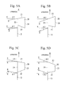
Figs. 5A through 5D show methods for attaching a reference unit to a casing; -
Fig. 6A is a back view of an in-vehicle radar apparatus in accordance with a second embodiment; -
Fig. 6B is a side view of the in-vehicle radar apparatus in accordance with the second embodiment; -
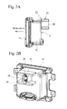
Fig. 7A is a front view of a reference unit employed in a third embodiment; -
Fig. 7B is a side view of the reference unit shown inFig. 7A ; -
Fig. 7C is a top view of the reference unit shown inFig. 7A ; and -
Fig. 8 is a perspective view of a reference unit employed in a fourth unit. - A description will now be given of a first embodiment of the present invention.
-
Fig. 1A is a perspective view of the front of an in-vehicle radar apparatus 10 in accordance with a first embodiment,Fig. 1B is a perspective view of the in-vehicle radar apparatus 10 from which a cover has been removed, andFig. 1C is a perspective view of the in-vehicle radar apparatus 10 to which a bracket is attached. Acover 14 for an antenna is provided to the front of acasing 12, as shown inFig. 1A . Anantenna 16, which is an exemplary beam emitting part, is mounted on thecasing 12, as shown inFig. 1B . A beam of a millimeter wave emitted from theantenna 16 passes through thecover 14 and is emitted forward. The direction of the center of beam emission is a beam axis B. As shown inFig. 1C , abracket 30 is used to attach the in-vehicle radar apparatus 10 to a vehicle.Adjustment bolts 32 are used to precisely align the direction of the beams axis B and the direction of the front of the vehicle with each other. -
Fig. 2A is a side view of the in-vehicle radar apparatus 10. Areference unit 20 is provided on aback surface 13 of thecasing 12. Thereference unit 20 is fixed to thecasing 12 on afixing surface 23 by a screw. A top surface of thereference unit 20 functions as areference plane 21.Fig. 2B is a perspective view of a back of the in-vehicle radar apparatus 10. Thereference unit 20 is fixed to theback surface 13 of thecasing 12 byscrews 34. -
Fig. 3 is a perspective view of the in-vehicle radar apparatus 10 attached to avehicle 50. The in-vehicle radar apparatus 10 is attached to a front of thevehicle 50, and the beam axis B is oriented in the front direction of thevehicle 50. When the in-vehicle radar apparatus 10 is attached to thevehicle 50, thebracket 30 is fixed to thevehicle 50. Next, as shown inFig. 4 , alevel 40 is placed on thereference plane 21 of thereference unit 20, and theadjustment bolts 32 are used to make thereference plane 21 horizontal. When the horizontal direction of thereference plane 21 is parallel to the beams axis B in the adjustment, the beam axis B can be set horizontal. It is no longer necessary to measure the intensity distribution of the beam for adjustment of the beam axis B at the time of attaching the in-vehicle radar apparatus 10 to thevehicle 50. According to the first embodiment, the attachment angle of thecasing 12 is adjusted based on thereference plane 21, so that the beam axis B can be adjusted in a desired direction. -
Figs. 5A through 5D schematically show four methods for fixing thereference unit 20 to theback surface 13 of thecasing 12. In these figures, K is the perpendicular line of theback surface 13 of thecasing 12, B is the beam axis, and S is the horizontal direction of thereference plane 21. The plane used as a reference faces upwards.Fig. 5A shows a case where the beam axis B is in a downward direction by an angle θ1' with respect to the perpendicular line K of theback surface 13. In this case, thereference unit 20 is fixed to theback surface 13 of thecasing 12 on the fixingsurface 23, and thesurface 21 of thereference unit 20 is the reference plane. The direction of thereference plane 21 is downwards by an angle θ1 with respect to the perpendicular line K of theback surface 13. When θ1 is approximately equal to θ1', the direction S of thereference plane 21 is made parallel to the beam axis B with a desired tolerance. -
Fig. 5B shows a case where the beam axis B is further downwards with respect to the perpendicular line K of theback surface 13 and is at an angle θ2', and thereference unit 20 is placed upside down so that asurface 22 of thereference unit 20 is used as the reference plane. It is thus possible to set the angle between the direction S of thereference plane 22 and the perpendicular line K of theback surface 13 equal to θ2 greater than θ1. Thus, when θ2 and θ2' are approximately equal to each other, the direction S of thereference plane 21 can be made parallel to the beam axis B within a desired tolerance. -
Fig. 5C shows a case where the beam axis B is in an upward direction with respect to the perpendicular line K of theback surface 13, and thereference unit 20 is fixed to theback surface 13 on a fixingsurface 24, thesurface 21 being used as the reference plane. Thus, when θ1 and θ1' are approximately equal to each other, the direction S of thereference plane 21 can be made parallel to the beam axis B within a desired tolerance. -
Fig. 5D shows a case where the axis B is further upwards by an angle θ2' (> θ2) with respect to the perpendicular line K of theback surface 13, and thereference unit 20 is fixed to theback surface 13 on the fixingsurface 24, thesurface 22 being used as the reference plane. Thus, when θ2 and θ2' are approximately equal to each other, the direction S of thereference plane 21 can be made parallel to the beam axis B within a desired tolerance. - The first embodiment measures the direction of the beam emission (beam axis B) from the antenna 16 (beam emitting part) attached to the
casing 12 and fixes thereference unit 20 to thecasing 12 so that an appropriate one of themultiple surfaces casing 12 to which thereference unit 20 is fixed and thereference plane single reference unit 20 functions as four different correction members for correcting the angle of the beam axis B with respect to thecasing 12. It is thus possible to reduce the number of types of components involved in correcting the beam axis B and reduce the number of management steps for components. - In the above-mentioned description of the first embodiment, the reference plane is the upward surface. The reference plane may be a surface that faces in a predetermined direction. The
reference unit 20 may be fixed to an arbitrary surface of thecasing 12 other than theback surface 13. Such an arbitrary surface may be the side, upper or lower surface of thecasing 12. When the reference plane faces upwards or downwards, it is possible to correct deviations of the beam axis B in the vertical direction (up and down directions) of thevehicle 50. Similarly, when the reference plane faces rightwards or leftwards, it is possible to correct deviations of the beam axis B in the horizontal direction (right and left directions) of thevehicle 50. It is thus possible to select an appropriate one of the direction of the reference plane taking into consideration the direction S of the beam axis B in which there is a deviation that affects the performance of the in-vehicle radar apparatus. It is also possible to provide thereference unit 20 with two reference planes and to thus correct deviations in the vertical and horizontal directions of the beam axis B. - As described above, the horizontal direction S of the reference plane (21 or 22) may be set approximately parallel to the beam direction B (beam emitting direction). Thus, the horizontal direction of the reference plane may be aligned with a desired direction in attachment of the in-
vehicle radar apparatus 10 to thevehicle 50, so that the beam can be set in the desired direction with respect to the vehicle. - It is enough to associate the
reference plane vehicle 50 while taking the constant angle into account. - The in-
vehicle radar apparatus 10 is fixed to thecasing 12 and has the bracket (attachment part) 30 for attachment to thevehicle 50. It is thus possible to attach the in-vehicle radar apparatus 10 to thevehicle 50. - The adjustment of the beam axis B using the reference plane may be carried out at the time of maintenance of the
vehicle 50. - In short, the first embodiment has the
antenna 16, thecasing 12 that supports theantenna 16, and thereference unit 20 that is attached to thecasing 12 and is equipped withmultiple surfaces reference unit 20 is attached and the reference plane forming an angle that depends on which one of the multiple surfaces is used as the reference plane. - A second embodiment is an exemplary in-vehicle radar apparatus in which the casing has multiple surfaces to which the
reference unit 20 may be attached.Fig. 6A schematically shows a back view of the in-vehicle radar apparatus of the second embodiment, andFig. 6 schematically shows a side view thereof. Thecasing 12 has twosurfaces surface 13a and a perpendicular line Kb of thesurface 13b form an angle θ3. Thus, the direction of the reference plane has different angles that depend on cases where thereference unit 20 is attached to thesurfaces reference units reference unit 20a, the direction Sa of thereference plane 21a with respect to the perpendicular line Ka of thesurface 13a has an angle θ1. For thereference unit 20b, the direction Sb of thereference plane 21b with respect to the perpendicular line Ka of thesurface 13a has an angle equal to θ1 + θ3. It is thus possible to define eight different reference planes using thereference unit 20 using four reference planes. As described above, when thecasing 12 has an increased number of surfaces for attachment of thereference unit 20, an increased number of reference planes are available. It is thus possible to further reduce the number of types of components and reduce the number of management steps for components. -
Figs. 7A through 7C show areference unit 20a employed in a third embodiment in which screw holes for fixing an in-vehicle radar apparatus to the casing are not illustrated for the sake of simplicity. In the third embodiment, for example, a surface S1 is fixed to the casing 12 (that is, the surface S1 is used as a fixing surface), and any of the surfaces S2 to S5 may be used as the reference plane. The surface S2 is used for attachment, and any of the surfaces S1, S3, S5 and S6 may be used as the reference plane. In this manner, any one of the surfaces S1 to S6 may be used for attachment, and any one of the surfaces S1 to S6 may be used as the reference plane. The third embodiment has the six surfaces, any of which may be used as the reference plane and used for attachment. The third embodiment is capable of providing a large number of reference planes by means of the single-piece reference unit, as compared to the first embodiment. -
Fig. 8 show areference unit 20b used in a fourth embodiment. A surface S18 or S19 of thereference unit 20b is used as a fixing surface through which thereference unit 20b is fixed to thecasing 12 using screw holes 36. Six surfaces S11 through S16 may be used as the reference plane. Thereference unit 20b of the fourth embodiment is capable of defining the multiple reference planes. - As in the cases of the first and fourth embodiments, the
reference unit surface 23 or S18, and thesurfaces surface 23 or S18. As in the case of the third embodiment, the surfaces of thereference unit 20a that may be used as multiple reference planes may include the fixing surface (for example, S1) and the surface opposite to the fixing surface (for example, S4). - The first through fourth embodiments are in-vehicle radar apparatuses that emit the beams forwards. The in-vehicle radar apparatus may emit the laser backwards. The beam is not limited to the millimeter wave but may be an electromagnetic wave, ultrasonic wave or infrared rays. The
reference units - The present invention is not limited to the specifically disclosed embodiments, but may include other embodiments and variations without departing from the scope of the present invention.
- The present application is based on
Japanese Patent Application No. 2006-317887
Claims (16)
- An in-vehicle radar apparatus comprising:a beam emitting part that emits a beam;a casing that supports the beam emitting part; anda reference unit that is attached to the casing and is equipped with multiple surfaces usable as a reference plane,wherein a surface of the casing to which the reference unit is attached and the reference plane form an angle that depends on which one of the multiple surfaces is used as the reference plane.
- The in-vehicle radar apparatus as claimed in claim 1, wherein the reference plane is associated with a direction in which the beam is emitted.
- Apparatus as claimed in claim 1 or claim 2,
wherein a horizontal direction of the reference plane is parallel to a direction in which the beam is emitted. - Apparatus as claimed in any of the preceding claims,
wherein the reference unit has a fixing surface attached to the casing, and the multiple surfaces include a surface that contacts the fixing surface. - The in-vehicle radar apparatus as claimed in any of claims 1 to 3,
wherein the reference unit has a fixing surface attached to the casing, and the multiple surfaces include the fixing surface and a surface opposite to the fixing surface. - The in-vehicle radar apparatus as claimed in any of the preceding claims,
wherein the casing has multiple surfaces to which the reference unit is attachable. - A method for manufacturing an in-vehicle radar apparatus comprising the steps of:measuring a direction of emission of a beam emitted from a beam emitting part supported by a casing; andattaching a reference unit to the casing so that one of multiple surfaces of the reference unit is used as a reference plane for adjusting the direction of emission of the beam.
- The method as claimed in claim 7, wherein the reference plane is associated with a direction of emission of the beam.
- The method as claimed in claim 7 or claim 8, wherein the step of attaching the reference unit to the casing includes a step of fixing the reference unit to the casing so that a horizontal direction of the reference plane is parallel to a direction of emission of the beam.
- A reference unit comprising:multiple surfaces usable as a reference plane; anda fixing surface used to attach the reference unit to a casing of an apparatus,wherein a surface of the casing to which the reference unit is attached and the reference plane form an angle that depends on which one of the multiple surfaces is used as the reference plane.
- The reference unit as claimed in claim 10,
wherein the multiple surfaces include opposite surfaces inclined at different angles with respect to the fixing surface. - The surface unit as claimed in claim 10, wherein the reference unit further includes another fixing surface opposite to the fixing surface.
- The surface unit as claimed in claim 10, wherein the fixing surface is one of the multiple surfaces.
- The surface unit as claimed in claim 10, wherein the multiple surfaces include a surface that contacts the fixing surface.
- The surface unit as claimed in claim 10, wherein the multiple surfaces include the fixing surface and a surface opposite to the fixing surface.
- A method for adjusting a direction of emission of a beam comprising the steps of:measuring the direction of emission of the beam emitted from a beam emitting part supported by a casing; andadjusting the direction of emission of the beams by attaching a reference unit to the casing so that one of multiple surfaces of the reference unit is used as a reference plane for adjusting the direction of emission of the beam, and the direction of emission of the beam is aligned with the reference plane.
Applications Claiming Priority (1)
| Application Number | Priority Date | Filing Date | Title |
|---|---|---|---|
| JP2006317887A JP4444265B2 (en) | 2006-11-27 | 2006-11-27 | Vehicular radar apparatus and method for manufacturing the same, reference section, and adjustment method of beam emitting direction |
Publications (1)
| Publication Number | Publication Date |
|---|---|
| EP1925947A1 true EP1925947A1 (en) | 2008-05-28 |
Family
ID=39135153
Family Applications (1)
| Application Number | Title | Priority Date | Filing Date |
|---|---|---|---|
| EP07121405A Ceased EP1925947A1 (en) | 2006-11-27 | 2007-11-23 | In-vehicle radar apparatus and method for manufacturing the same |
Country Status (4)
| Country | Link |
|---|---|
| US (1) | US7675460B2 (en) |
| EP (1) | EP1925947A1 (en) |
| JP (1) | JP4444265B2 (en) |
| CN (1) | CN101191834A (en) |
Cited By (2)
| Publication number | Priority date | Publication date | Assignee | Title |
|---|---|---|---|---|
| WO2017200739A1 (en) * | 2016-05-18 | 2017-11-23 | Illinois Tool Works Inc. | System for mounting radars on vehicles |
| EP3192686A4 (en) * | 2014-12-26 | 2018-02-21 | Faltec Co., Ltd. | Grille shutter module |
Families Citing this family (15)
| Publication number | Priority date | Publication date | Assignee | Title |
|---|---|---|---|---|
| JP2008157815A (en) * | 2006-12-25 | 2008-07-10 | Fujitsu Ten Ltd | Radar apparatus for vehicle and its manufacturing method |
| US8405541B2 (en) | 2010-09-01 | 2013-03-26 | Toyota Motor Engineering & Manufacturing North America, Inc. | Multi-range radar system |
| KR101335074B1 (en) * | 2012-03-02 | 2013-12-03 | 주식회사 만도 | Alignment system and method of radar apparatus |
| DE102012204267A1 (en) * | 2012-03-19 | 2013-09-19 | Robert Bosch Gmbh | Sensor holder for a sensor for object detection |
| KR101459910B1 (en) * | 2013-05-28 | 2014-11-07 | 현대자동차주식회사 | Radar apparatus for vehicle |
| US9673517B2 (en) | 2014-04-30 | 2017-06-06 | Honda Motor Co., Ltd. | Vehicle radar cover assembly and method |
| US9828036B2 (en) * | 2015-11-24 | 2017-11-28 | Srg Global Inc. | Active grille shutter system with integrated radar |
| US10534081B2 (en) * | 2016-05-02 | 2020-01-14 | Magna Electronics Inc. | Mounting system for vehicle short range sensors |
| US9956993B1 (en) * | 2017-01-20 | 2018-05-01 | Ford Global Technologies, Llc | Vehicle front impact sensor with impact resistant carriage |
| JP7037998B2 (en) * | 2018-04-19 | 2022-03-17 | 本田技研工業株式会社 | Transport equipment |
| JP7045249B2 (en) * | 2018-04-19 | 2022-03-31 | 本田技研工業株式会社 | Transport equipment |
| JP6973350B2 (en) * | 2018-10-22 | 2021-11-24 | 豊田合成株式会社 | Fixed structure of radio wave radar device |
| US11108147B2 (en) * | 2018-11-13 | 2021-08-31 | Honda Motor Co., Ltd. | Antenna protector |
| JP6952677B2 (en) * | 2018-12-04 | 2021-10-20 | 本田技研工業株式会社 | Detector and vehicle |
| CN113093114A (en) * | 2021-04-06 | 2021-07-09 | 深圳市道通科技股份有限公司 | Automobile millimeter wave radar fixing device |
Citations (3)
| Publication number | Priority date | Publication date | Assignee | Title |
|---|---|---|---|---|
| JP2003255042A (en) | 2002-03-06 | 2003-09-10 | Honda Motor Co Ltd | Adjustment method of detection axis of object detection device |
| US20040017308A1 (en) * | 2002-06-04 | 2004-01-29 | Hayato Kikuchi | Method for adjusting detection axis of object detection system |
| EP1480055A1 (en) | 2003-05-23 | 2004-11-24 | Fujitsu Ten Limited | Radar apparatus for automobile, attachment direction adjuster and attachment direction adjusting method for radar apparatus |
Family Cites Families (9)
| Publication number | Priority date | Publication date | Assignee | Title |
|---|---|---|---|---|
| GB0002294D0 (en) * | 2000-02-02 | 2000-03-22 | Jaguar Cars | Automotive radar elevation alignment |
| EP1130416A3 (en) * | 2000-03-02 | 2002-01-30 | Denso Corporation | Forward condition detecting apparatus for vehicles |
| JP3427817B2 (en) * | 2000-03-31 | 2003-07-22 | 株式会社デンソー | Vehicle obstacle recognition method and apparatus, recording medium |
| EP1231480B1 (en) * | 2001-02-08 | 2006-06-21 | Fujitsu Ten Limited | Method and device for aligning radar mount direction, and radar aligned by the method or device |
| JP4698087B2 (en) * | 2001-08-15 | 2011-06-08 | 富士通テン株式会社 | Radar horizontal axis deviation occurrence detection apparatus, axis deviation determination apparatus, and axis deviation correction apparatus |
| JP3676757B2 (en) | 2002-06-04 | 2005-07-27 | 本田技研工業株式会社 | Method for adjusting detection axis of object detection device |
| JP3676758B2 (en) | 2002-06-04 | 2005-07-27 | 本田技研工業株式会社 | Axis adjusting device for moving body mounting device |
| US6714156B1 (en) * | 2002-11-22 | 2004-03-30 | Visteon Global Technologies, Inc. | Method for correcting radar misalignment |
| JP2007125928A (en) * | 2005-11-01 | 2007-05-24 | Mazda Motor Corp | Obstacle detection device for vehicles |
-
2006
- 2006-11-27 JP JP2006317887A patent/JP4444265B2/en not_active Expired - Fee Related
-
2007
- 2007-11-23 EP EP07121405A patent/EP1925947A1/en not_active Ceased
- 2007-11-26 US US11/984,985 patent/US7675460B2/en not_active Expired - Fee Related
- 2007-11-27 CN CNA2007101934545A patent/CN101191834A/en active Pending
Patent Citations (3)
| Publication number | Priority date | Publication date | Assignee | Title |
|---|---|---|---|---|
| JP2003255042A (en) | 2002-03-06 | 2003-09-10 | Honda Motor Co Ltd | Adjustment method of detection axis of object detection device |
| US20040017308A1 (en) * | 2002-06-04 | 2004-01-29 | Hayato Kikuchi | Method for adjusting detection axis of object detection system |
| EP1480055A1 (en) | 2003-05-23 | 2004-11-24 | Fujitsu Ten Limited | Radar apparatus for automobile, attachment direction adjuster and attachment direction adjusting method for radar apparatus |
Cited By (3)
| Publication number | Priority date | Publication date | Assignee | Title |
|---|---|---|---|---|
| EP3192686A4 (en) * | 2014-12-26 | 2018-02-21 | Faltec Co., Ltd. | Grille shutter module |
| US10118480B2 (en) | 2014-12-26 | 2018-11-06 | Faltec Co., Ltd. | Grille shutter module |
| WO2017200739A1 (en) * | 2016-05-18 | 2017-11-23 | Illinois Tool Works Inc. | System for mounting radars on vehicles |
Also Published As
| Publication number | Publication date |
|---|---|
| JP2008128995A (en) | 2008-06-05 |
| CN101191834A (en) | 2008-06-04 |
| US7675460B2 (en) | 2010-03-09 |
| JP4444265B2 (en) | 2010-03-31 |
| US20080122682A1 (en) | 2008-05-29 |
Similar Documents
| Publication | Publication Date | Title |
|---|---|---|
| US7675460B2 (en) | In-vehicle radar apparatus and method for manufacturing the same | |
| CN110007292B (en) | Laser radar zero calibration method and calibration system | |
| CN112585493B (en) | Laser transceiver module and its light modulation method, laser radar and automatic driving equipment | |
| KR102673029B1 (en) | Lidar optical apparatus | |
| US10239468B2 (en) | Method of attaching vehicle-mounted camera | |
| EP2363726A1 (en) | Compact laser rangefinder | |
| US7424184B2 (en) | Optical member and optical communication module with easy height adjustment | |
| EP2728378A1 (en) | Optical sensor | |
| EP4160262A1 (en) | Lidar comprising two laser emission modules | |
| US20210336322A1 (en) | Fastening device and associated method | |
| US20160036135A1 (en) | Antenna array having a variable directivity characteristic | |
| US20220334230A1 (en) | Lidar and automobile | |
| EP2439553A1 (en) | Sensor, adjustment method and measuring procedure for a sensor | |
| JP5173473B2 (en) | Beam direction correction method for emblem and radar wave | |
| US7147370B2 (en) | Light irradiator, lamp assembly, and X-ray apparatus | |
| JP6968901B2 (en) | Transmitters, Photosensors, and Automatic Vehicles for Photosensors of Automatic Vehicles with Specific Pre-Assembly Modules | |
| JP2001228238A (en) | Apparatus and method for correcting azimuth axis of electromagnetic wave, radar apparatus, method for correcting azimuth axis, and radome for radar apparatus | |
| US20200127738A1 (en) | Optical communication device | |
| US20130300858A1 (en) | Methods and systems for performing vision-aided passive alignment during the assembly of an optical communications module | |
| CN111766562A (en) | Tunnel tunneling guiding method and system | |
| JP2008157815A (en) | Radar apparatus for vehicle and its manufacturing method | |
| JP2007033254A (en) | Anechoic chamber | |
| JP2001349937A (en) | On-vehicle radar device | |
| JP2000082907A (en) | Antenna device and its assembling method | |
| WO2021125018A1 (en) | Light emitting device, object detecting device, and mobile body |
Legal Events
| Date | Code | Title | Description |
|---|---|---|---|
| PUAI | Public reference made under article 153(3) epc to a published international application that has entered the european phase |
Free format text: ORIGINAL CODE: 0009012 |
|
| AK | Designated contracting states |
Kind code of ref document: A1 Designated state(s): AT BE BG CH CY CZ DE DK EE ES FI FR GB GR HU IE IS IT LI LT LU LV MC MT NL PL PT RO SE SI SK TR |
|
| AX | Request for extension of the european patent |
Extension state: AL BA HR MK RS |
|
| 17P | Request for examination filed |
Effective date: 20081117 |
|
| AKX | Designation fees paid |
Designated state(s): DE FR GB |
|
| 17Q | First examination report despatched |
Effective date: 20110407 |
|
| STAA | Information on the status of an ep patent application or granted ep patent |
Free format text: STATUS: THE APPLICATION HAS BEEN REFUSED |
|
| 18R | Application refused |
Effective date: 20120510 |