EP1925892A2 - Heat pump - Google Patents
Heat pump Download PDFInfo
- Publication number
- EP1925892A2 EP1925892A2 EP07450207A EP07450207A EP1925892A2 EP 1925892 A2 EP1925892 A2 EP 1925892A2 EP 07450207 A EP07450207 A EP 07450207A EP 07450207 A EP07450207 A EP 07450207A EP 1925892 A2 EP1925892 A2 EP 1925892A2
- Authority
- EP
- European Patent Office
- Prior art keywords
- heat pump
- pressure
- pressure region
- thermal energy
- providing electrical
- Prior art date
- Legal status (The legal status is an assumption and is not a legal conclusion. Google has not performed a legal analysis and makes no representation as to the accuracy of the status listed.)
- Withdrawn
Links
- 238000001816 cooling Methods 0.000 claims description 17
- 238000000034 method Methods 0.000 claims description 14
- 238000007639 printing Methods 0.000 claims description 6
- 230000009467 reduction Effects 0.000 claims description 4
- 230000008569 process Effects 0.000 claims description 3
- 239000002918 waste heat Substances 0.000 claims description 2
- 239000003507 refrigerant Substances 0.000 description 25
- 230000008901 benefit Effects 0.000 description 5
- 238000010438 heat treatment Methods 0.000 description 5
- 230000008878 coupling Effects 0.000 description 3
- 238000010168 coupling process Methods 0.000 description 3
- 238000005859 coupling reaction Methods 0.000 description 3
- 238000010586 diagram Methods 0.000 description 3
- 239000012530 fluid Substances 0.000 description 3
- 230000001419 dependent effect Effects 0.000 description 2
- 238000005265 energy consumption Methods 0.000 description 2
- 238000005259 measurement Methods 0.000 description 2
- 238000011084 recovery Methods 0.000 description 2
- CBENFWSGALASAD-UHFFFAOYSA-N Ozone Chemical compound [O-][O+]=O CBENFWSGALASAD-UHFFFAOYSA-N 0.000 description 1
- 230000004888 barrier function Effects 0.000 description 1
- 238000006243 chemical reaction Methods 0.000 description 1
- 230000001427 coherent effect Effects 0.000 description 1
- 238000001704 evaporation Methods 0.000 description 1
- 239000003673 groundwater Substances 0.000 description 1
- 230000009931 harmful effect Effects 0.000 description 1
- 230000001771 impaired effect Effects 0.000 description 1
- 239000008235 industrial water Substances 0.000 description 1
- 238000004064 recycling Methods 0.000 description 1
- 238000005057 refrigeration Methods 0.000 description 1
- 238000000926 separation method Methods 0.000 description 1
- 230000009182 swimming Effects 0.000 description 1
Images


Classifications
-
- F—MECHANICAL ENGINEERING; LIGHTING; HEATING; WEAPONS; BLASTING
- F25—REFRIGERATION OR COOLING; COMBINED HEATING AND REFRIGERATION SYSTEMS; HEAT PUMP SYSTEMS; MANUFACTURE OR STORAGE OF ICE; LIQUEFACTION SOLIDIFICATION OF GASES
- F25B—REFRIGERATION MACHINES, PLANTS OR SYSTEMS; COMBINED HEATING AND REFRIGERATION SYSTEMS; HEAT PUMP SYSTEMS
- F25B30/00—Heat pumps
- F25B30/06—Heat pumps characterised by the source of low potential heat
-
- F—MECHANICAL ENGINEERING; LIGHTING; HEATING; WEAPONS; BLASTING
- F25—REFRIGERATION OR COOLING; COMBINED HEATING AND REFRIGERATION SYSTEMS; HEAT PUMP SYSTEMS; MANUFACTURE OR STORAGE OF ICE; LIQUEFACTION SOLIDIFICATION OF GASES
- F25B—REFRIGERATION MACHINES, PLANTS OR SYSTEMS; COMBINED HEATING AND REFRIGERATION SYSTEMS; HEAT PUMP SYSTEMS
- F25B1/00—Compression machines, plants or systems with non-reversible cycle
- F25B1/10—Compression machines, plants or systems with non-reversible cycle with multi-stage compression
-
- F—MECHANICAL ENGINEERING; LIGHTING; HEATING; WEAPONS; BLASTING
- F25—REFRIGERATION OR COOLING; COMBINED HEATING AND REFRIGERATION SYSTEMS; HEAT PUMP SYSTEMS; MANUFACTURE OR STORAGE OF ICE; LIQUEFACTION SOLIDIFICATION OF GASES
- F25B—REFRIGERATION MACHINES, PLANTS OR SYSTEMS; COMBINED HEATING AND REFRIGERATION SYSTEMS; HEAT PUMP SYSTEMS
- F25B27/00—Machines, plants or systems, using particular sources of energy
- F25B27/002—Machines, plants or systems, using particular sources of energy using solar energy
- F25B27/005—Machines, plants or systems, using particular sources of energy using solar energy in compression type systems
-
- F—MECHANICAL ENGINEERING; LIGHTING; HEATING; WEAPONS; BLASTING
- F25—REFRIGERATION OR COOLING; COMBINED HEATING AND REFRIGERATION SYSTEMS; HEAT PUMP SYSTEMS; MANUFACTURE OR STORAGE OF ICE; LIQUEFACTION SOLIDIFICATION OF GASES
- F25B—REFRIGERATION MACHINES, PLANTS OR SYSTEMS; COMBINED HEATING AND REFRIGERATION SYSTEMS; HEAT PUMP SYSTEMS
- F25B13/00—Compression machines, plants or systems, with reversible cycle
-
- F—MECHANICAL ENGINEERING; LIGHTING; HEATING; WEAPONS; BLASTING
- F25—REFRIGERATION OR COOLING; COMBINED HEATING AND REFRIGERATION SYSTEMS; HEAT PUMP SYSTEMS; MANUFACTURE OR STORAGE OF ICE; LIQUEFACTION SOLIDIFICATION OF GASES
- F25B—REFRIGERATION MACHINES, PLANTS OR SYSTEMS; COMBINED HEATING AND REFRIGERATION SYSTEMS; HEAT PUMP SYSTEMS
- F25B2313/00—Compression machines, plants or systems with reversible cycle not otherwise provided for
- F25B2313/027—Compression machines, plants or systems with reversible cycle not otherwise provided for characterised by the reversing means
- F25B2313/02741—Compression machines, plants or systems with reversible cycle not otherwise provided for characterised by the reversing means using one four-way valve
-
- F—MECHANICAL ENGINEERING; LIGHTING; HEATING; WEAPONS; BLASTING
- F25—REFRIGERATION OR COOLING; COMBINED HEATING AND REFRIGERATION SYSTEMS; HEAT PUMP SYSTEMS; MANUFACTURE OR STORAGE OF ICE; LIQUEFACTION SOLIDIFICATION OF GASES
- F25B—REFRIGERATION MACHINES, PLANTS OR SYSTEMS; COMBINED HEATING AND REFRIGERATION SYSTEMS; HEAT PUMP SYSTEMS
- F25B40/00—Subcoolers, desuperheaters or superheaters
- F25B40/04—Desuperheaters
Definitions
- the invention relates to a method for operating a heat pump with the features of the preamble of claim 20.
- a working medium such as a refrigerant
- mechanical work i. brought to a higher temperature level
- expanded with release of mechanical work i. brought to a lower temperature level.
- the invention is based on the object to provide a heat pump and a method of the type mentioned are available with which heat pumps can be significantly optimized in terms of performance and space requirements.
- thermovoltaic element As a device for providing electrical and thermal energy, wherein in the context of the invention, other devices for providing electrical and thermal energy, such. a thermovoltaic element, can find application.
- the photovoltaic element is thermally coupled to the low pressure region.
- the heat supplied to the working medium in the low pressure is obtained by cooling the photovoltaic element, wherein the thermal energy of the photovoltaic element for evaporating the working medium, in this case a refrigerant is used.
- the efficiency is significantly improved by the thermal energy withdrawal at the photovoltaic element. It is particularly advantageous that in this embodiment of the invention, the sun-irradiated area of the photovoltaic element in comparison to the known solar thermal energy can be reduced in the range of 50%, which areas can be optimally planned.
- the cooling capacity of the heat pump thus serves to cool the photovoltaic element, which thereby achieves a better efficiency, at the same time the photovoltaic element serves as a thermal energy source for the heat pump.
- the coupling of the photovoltaic element with the low-pressure region of the heat pump can be carried out both directly and indirectly within the scope of the invention.
- the direct coupling of the photovoltaic element to the circulation of the working medium takes place in such a way that the working medium in the low pressure range is passed directly through the device for providing electrical and thermal energy.
- a heat exchanger is arranged in the low pressure region, through which the working medium is guided, wherein the heat exchanger is coupled to the device for providing electrical and thermal energy.
- the photovoltaic element is electrically coupled to the pressure elevation device so that the pressure elevation device is operated with the current generated by the photovoltaic element.
- the photovoltaic element becomes the thermal and electrical energy source of the heat pump, whereby the system of heat pump and thermally and electrically integrated photovoltaic element without further energy supply, such as. Mains power, can be operated.
- the invention therefore allows not only significant advantages for commercial use in terms of energy saving, environmentally friendly use of energy and improving the performance of system components, but is also attractive for private use by the optimal land area planning in the sense of halving the previously required area, since the invention Heat pump customizable to customer requirements. All these advantages are of particular importance for the future development of private or commercial energy consumption.
- Further particularly preferred embodiments have two devices for printing heights, wherein a medium-pressure region is formed between the two devices for printing heights.
- the two pressure-increasing devices can be two compressors or one compressor and at least one pump.
- the first compressor being arranged between the low-pressure and medium-pressure regions
- the second compressor being arranged between the medium-pressure and high-pressure regions.
- the first compressor is referred to as a medium-pressure compressor and the second compressor as a high-pressure compressor.
- the feeding of further heat into the medium-pressure region can take place such that excess heat from the high-pressure region is returned to the medium-pressure region (preheating of the working medium).
- a heat exchanger is arranged in the medium-pressure region, the temperature of the working medium in the high-pressure region can be transmitted to the working medium in the medium-pressure region via this heat exchanger.
- the heat introduced into the medium pressure range increases the pressure of the working fluid.
- the reduction in power consumption is essentially proportional to how the pressure in the mid-pressure range increases by the supply of heat. Another benefit of energy recycling is that the excess heat does not have to be released to the environment.
- temperatures which are between the temperatures in the low-pressure range and the high-pressure range can be fed into the medium-pressure range.
- This temperature range is designed so that directly into the medium pressure range thermal energy, i. Heat, from devices for providing thermal and optionally electrical energy, e.g. Photovoltaic or thermovoltaic elements, as well as energy from process or waste heat or from a cooling device, e.g. for cooling photovoltaic and / or thermovoltaic elements, can be fed, which continues to save considerable energy costs.
- the thermal energy can be used directly to increase the pressure of the working fluid in the medium pressure range and thus to reduce the required current ,
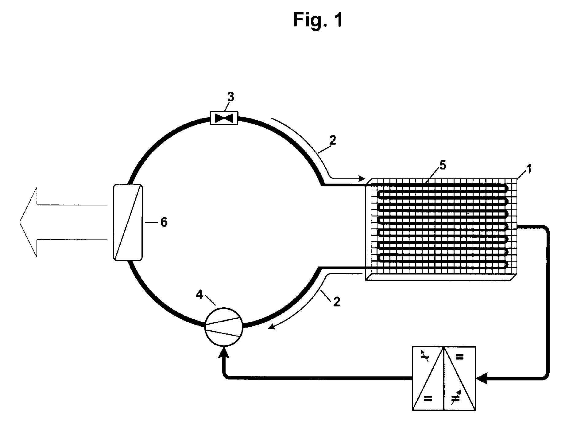
- FIG. 1 a flow diagram of an embodiment of a heat pump according to the invention
- Fig. 2 a flow diagram of a second embodiment of a heat pump according to the invention
- Fig. 3 a flow diagram of a third embodiment of a heat pump according to the invention
- Fig. 4 an embodiment of the heat pump according to the invention in a schematic representation.
- Fig. 1 is a highly simplified illustrated embodiment of a heat pump according to the invention in a connection to be described with a photovoltaic element 1 as a device for providing thermal and electrical energy shown.
- a refrigerant is fed as a working medium in the direction of arrow 2 in the circuit.
- the refrigerant cycle can be divided into two areas: an area in which the refrigerant in the heat pump has a low pressure and a low temperature (hereinafter referred to as a low pressure area) and an area in which the refrigerant has a higher pressure and a higher temperature (hereinafter referred to as high pressure area).
- the low-pressure region is limited in the flow direction of the refrigerant (arrow 2) by a throttle 3 and a compressor 4, wherein the compressor 4 compresses the refrigerant to the pressures and temperatures prevailing in the high-pressure region.
- the throttle 3 is in the embodiment shown an expansion valve and controls the volume flow of the refrigerant, which determines the energy conversion of the heat pump.
- the high pressure area in the flow direction of the refrigerant (arrow 2) is limited by the compressor 4 and the throttle 3, wherein the throttle 3, the refrigerant to the pressures and temperatures prevailing in the low pressure region expanded. Due to the reduction in temperature of the refrigerant obtained at the throttle 3, the refrigeration for cooling consumer appliances can be provided.
- the photovoltaic element 1 In the low-pressure region, the photovoltaic element 1 is coupled directly to the circuit of the working medium, wherein the refrigerant is passed directly through the photovoltaic element 1 by means of a line 5, which is partially arranged on or in the photovoltaic element 1.
- the photovoltaic element 1 is cooled by the heat pump, the photovoltaic element 1 is the thermal energy source for the heat pump.
- a line is considered equivalent to a coherent line system.
- a heat exchanger 6 In the high-pressure area, a heat exchanger 6 is arranged, can be discharged via the heat to consumer equipment.
- Fig. 2 shows a second embodiment of a heat pump according to the invention, the division into low pressure and high pressure range of the Fig. 1 corresponds to the division described. Also in this embodiment, a photovoltaic element 1 is thermally and electrically coupled to the heat pump.
- a heat exchanger 7 is arranged in the low-pressure region, from which a line 8 goes out, which is arranged in regions on or in the photovoltaic element 1.
- Fig. 3 shows a third embodiment of a heat pump according to the invention, their division into low pressure range and high pressure range of the to Fig. 1 and 2 deviates described embodiments.
- the refrigerant is circulated in the direction of arrow 2, whereby the refrigerant circuit can be subdivided into three areas: the low-pressure area, the high-pressure area and a additional area in which pressure and temperature of the refrigerant between the two aforementioned areas (hereinafter referred to as the medium-pressure area).
- the low-pressure region is in turn limited in the flow direction of the refrigerant (arrow 2) by the throttle 3 and a first compressor 9, wherein the first compressor 9 (medium-pressure compressor) compresses the refrigerant to the pressures and temperatures prevailing in the medium pressure range.
- the high pressure area is limited in the flow direction of the refrigerant (arrow 2) by a second compressor 10 and the throttle 3, wherein the second compressor 5 (high pressure compressor) compresses the refrigerant to the pressures and temperatures prevailing in the high pressure region and the throttle 3, the refrigerant to the in the Low pressure range prevailing pressures and temperatures expanded.
- a compressor 9 or 10 and at least one pump are provided to form the medium-pressure region.
- first compressor 9 and the second compressor 10 of the medium pressure range are created in which before the second compressor 10 thermal energy can be introduced without changing the cooling capacity in the low pressure range, since the first compressor 9 acts as a pressure barrier, if in the medium-pressure thermal Energy is introduced.
- thermal energy is introduced into the medium-pressure region, wherein in the context of the invention, other possibilities are conceivable.
- a heat exchanger 11 is arranged between the first compressor 9 and the second compressor 10.
- the first compressor 9 Starting from the arranged in the high-pressure region heat exchanger 6, through which the heating power could otherwise be used for example for hot or industrial water treatment, runs a line 12, which opens into the heat exchanger 11.
- the thus fed into the medium-pressure area (recirculated) heat raises the pressure of the refrigerant in front of the second compressor 10, whereby the torque for Compressing the refrigerant to the pressure prevailing in the high pressure area is smaller.
- the power consumption of the second compressor 10 is reduced by the portion of the injected energy, with the result that the coefficient of performance and the energy balance of the heat pump is optimized.
- thermal energy feed into the medium-pressure region is the heat supply from the photovoltaic element 1.
- This thermal energy supply can e.g. by means of a medium, which was previously used for cooling the photovoltaic element 1, take place (while also the cooling power generated by the heat pump can be used directly for cooling the photovoltaic element 1).
- a line 8 is provided, which opens into the heat exchanger 11.
- the temperature range which is fed within the medium-pressure region is designed so that the heat supplied by the photovoltaic element 1 achieves the desired efficiency.
- connection of the photovoltaic element 1 to the heat pump is best Fig. 4 and will be described below with reference to an embodiment according to Fig. 3 , ie with a medium pressure range explained.
- the electrical connection of the photovoltaic element 1 with the heat pump in particular the feeding of the current generated by the photovoltaic element 1 to a compressor 4, 9, 10, can also on the in the Fig. 1 and 2 described embodiments take place.
- the photovoltaic element 1 electrical energy is generated, with which two compressors 9, 10 are operated with wholly or partially solar energy.
- the resulting solar heat is used as described above directly to increase the pressure of the refrigerant in the medium pressure range of the heat pump.
- the cooling power generated by the heat pump is introduced directly for cooling the photovoltaic element 1.
- the electrical power of the photovoltaic element 1 can be significantly increased.
- the saving of other electrical energy in this heat pump is up to 100% compared to known from the prior art heat pumps, being lowered in the cooling mode by the inventive return of the heating power in the medium pressure range, the electrical energy consumption.
- the electrical energy of the photovoltaic element 1 is supplied to a DC / DC converter 13 in its direct connection to the heat pump.
- the photovoltaic element 1 is connected to a frequency converter 14.
- the energy to be supplied by the photovoltaic element 1 is adjusted to the energy demand of the two compressors 9, 10 that is dependent on the heat pump output.
- the frequency converter 14 operates the two compressors 9, 10 with variable frequency for controlling the compressor powers.
- thermovoltaic elements 17 as a device for providing thermal and / or electrical energy.
- the thermovoltaic elements 17 are arranged in the embodiment shown in the form of thermal generators in the heat exchanger 6, but can also be arranged in other heat exchangers of the heat pump.
- the electrical energy generated is analogous to the photovoltaic element 1 via a DC / DC converter 13 to the frequency converter 14 and fed to the control system 16 and the device 15 for power measurement of the Energy requirement of the compressor 9, 10 adapted.
- the heat pump can be switched with the valve 18 each from the heating mode to the cooling mode.
- a refrigerant is preferably used as the working medium, which exerts as little harmful effect on the environment and in particular on the ozone layer of the earth in case of accidental leakage from the heat pump.
- Fig. 4 shown components of the heat pump according to the invention, such as the connection to a heat reservoir 19, eg geothermal or groundwater, or the connection to a consumer device, such as a refrigerator, or the connection to the electrical network 20, in known from the prior art manner be executed.
- a heat reservoir 19 eg geothermal or groundwater
- a consumer device such as a refrigerator
- the connection to the electrical network 20 in known from the prior art manner be executed.
- a heat pump leads a working medium in the circuit and has at least one device 3 for pressure reducing and at least one device 4, 9, 10 for pressure heights and on.
- the heat pump is electrically and thermally coupled to a device 1, 17 for providing electrical and thermal energy, wherein the device 1, 17 for providing electrical and thermal energy is the electrical and thermal energy source for the heat pump.
Landscapes
- Engineering & Computer Science (AREA)
- Physics & Mathematics (AREA)
- Mechanical Engineering (AREA)
- Thermal Sciences (AREA)
- General Engineering & Computer Science (AREA)
- Life Sciences & Earth Sciences (AREA)
- Sustainable Development (AREA)
- Sustainable Energy (AREA)
- Heat-Pump Type And Storage Water Heaters (AREA)
- Structures Of Non-Positive Displacement Pumps (AREA)
Abstract
Eine Wärmepumpe führt ein Arbeitsmedium im Kreislauf und weist wenigstens eine Vorrichtung (3) zum Druckmindern und wenigstens eine Vorrichtung (4, 9, 10) zum Druckerhöhen und auf. Die Wärmepumpe ist mit einer Vorrichtung (1, 17) zum Bereitstellen von elektrischer und thermischer Energie elektrisch und thermisch gekoppelt ist, wobei die Vorrichtung (1, 17) zum Bereitstellen von elektrischer und thermischer Energie die elektrische und thermische Energiequelle für die Wärmepumpe darstellt.
Description
Des Weiteren betrifft die Erfindung ein Verfahren zum Betreiben einer Wärmepumpe mit den Merkmalen des Oberbegriffes des Anspruches 20.Furthermore, the invention relates to a method for operating a heat pump with the features of the preamble of
Das Arbeitsprinzip von Wärmepumpen sowie Wärmepumpen zum Heizen oder Kühlen von Gebäuden, Schwimmbädern, etc., sind an sich aus dem Stand der Technik bekannt. Dabei wird ein Arbeitsmedium, wie ein Kältemittel, wechselweise durch Aufbringen von mechanischer Arbeit verdichtet, d.h. auf ein höheres Temperaturniveau gebracht, und unter Abgabe von mechanischer Arbeit expandiert, d.h. auf ein niedrigeres Temperaturniveau gebracht.The operating principle of heat pumps and heat pumps for heating or cooling buildings, swimming pools, etc., are known per se from the prior art. In this case, a working medium, such as a refrigerant, is alternately compressed by applying mechanical work, i. brought to a higher temperature level, and expanded with release of mechanical work, i. brought to a lower temperature level.
Bei solchen Wärmepumpen ist es bekannt, zum Erhöhen des Temperaturniveaus einen Verdichter zu verwenden, wobei der Verdichter einen Bereich mit niedrigem Druck ("kalte Seite") und einen Bereich mit hohem Druck ("warme Seite") trennt. Zum Absenken des Temperaturniveaus kann eine Drossel verwendet werden, welche eine zweite Trennstelle zwischen der kalten und der warmen Seite der Wärmepumpe darstellt. Die Verdichterarbeit, um das Arbeitsmedium von einem niedrigen auf einen hohen Druck zu bringen, stellt in der Wärmepumpe einen sehr energieaufwändigen Vorgang dar.In such heat pumps, it is known to use a compressor to increase the temperature level, with the compressor separating a low pressure area ("cold side") and a high pressure area ("warm side"). To lower the temperature level, a throttle can be used, which represents a second separation point between the cold and the warm side of the heat pump. The compressor work, to bring the working fluid from a low to a high pressure, is in the heat pump is a very energy-consuming process.
Es ist bekannt, den für die Verdichterarbeit erforderlichen elektrischen Strom zu einem Teil aus einem Photovoltaik-Element und zum anderen Teil aus dem Netzstrom zu beziehen. Diese bekannte, teilweise Einspeisung von elektrischem Strom aus dem Photovoltaik-Element bedeutet jedoch lediglich einen weiteren Flächenbedarf für das Photovoltaik-Element, ohne Auswirkung auf die Leistung der Wärmepumpe und/oder des Photovoltaik-Elements.It is known to obtain the required for the compressor work electrical power to a part of a photovoltaic element and the other part of the mains current. However, this known, partial supply of electrical current from the photovoltaic element only means a further area requirement for the photovoltaic element, without affecting the performance of the heat pump and / or the photovoltaic element.
Der Erfindung liegt die Aufgabe zu Grunde, eine Wärmepumpe sowie ein Verfahren der eingangs genannten Gattung zur Verfügung zu stellen, mit denen Wärmepumpen hinsichtlich Leistung und Flächenbedarf deutlich optimiert werden können.The invention is based on the object to provide a heat pump and a method of the type mentioned are available with which heat pumps can be significantly optimized in terms of performance and space requirements.
Gelöst wird diese Aufgabe erfindungsgemäß mit einer Wärmepumpe, welche die Merkmale des Anspruches 1 aufweist.This object is achieved according to the invention with a heat pump, which has the features of claim 1.
Des Weiteren wird diese Aufgabe erfindungsgemäß mit einem Verfahren gelöst, welches die Merkmale des Anspruches 20 aufweist.Furthermore, this object is achieved according to the invention with a method which has the features of
Bevorzugte und vorteilhafte Ausführungsformen der Erfindung sind Gegenstand der Unteransprüche.Preferred and advantageous embodiments of the invention are subject of the dependent claims.
Da bei der erfindungsgemäßen Wärmepumpe eine Vorrichtung zum Bereitstellen von elektrischer und thermischer Energie elektrisch und thermisch mit der Wärmepumpe gekoppelt ist, wird die thermische Leistung der Wärmepumpe vervielfacht. Dieser höhere Nutzen führt zu einem geringeren Platzbedarf für die erfindungsgemäße Wärmepumpe.Since, in the heat pump according to the invention, a device for providing electrical and thermal energy is electrically and thermally coupled to the heat pump, the thermal output of the heat pump is multiplied. This higher benefit leads to a smaller space requirement for the heat pump according to the invention.
Besonders bevorzugte Ausführungsformen werden im folgenden am Beispiel eines Photovoltaik-Elements als Vorrichtung zum Bereitstellen von elektrischer und thermischer Energie beschrieben, wobei im Rahmen der Erfindung auch andere Vorrichtungen zum Bereitstellen von elektrischer und thermischer Energie, wie z.B. ein Thermovoltaik-Element, Anwendung finden können.Particularly preferred embodiments are described in the following using the example of a photovoltaic element as a device for providing electrical and thermal energy, wherein in the context of the invention, other devices for providing electrical and thermal energy, such. a thermovoltaic element, can find application.
Vorzugsweise ist das Photovoltaik-Element thermisch mit dem Niederdruckbereich gekoppelt. Die dem Arbeitsmedium im Niederdruck zugeführte Wärme wird durch das Kühlen des Photovoltaik-Elements erhalten, wobei die thermische Energie des Photovoltaik-Elements zum Verdampfen des Arbeitsmediums, in diesem Fall ein Kältemittel, genutzt wird. Dabei wird durch den thermischen Energieentzug am Photovoltaik-Element dessen Wirkungsgrad wesentlich verbessert. Besonders vorteilhaft ist, dass in dieser Ausführungsform der Erfindung die sonnenbestrahlte Fläche des Photovoltaik-Elements im Vergleich zur bekannten Solarthermie im Bereich von 50 % reduziert werden kann, womit Nutzflächen optimaler geplant werden können.Preferably, the photovoltaic element is thermally coupled to the low pressure region. The heat supplied to the working medium in the low pressure is obtained by cooling the photovoltaic element, wherein the thermal energy of the photovoltaic element for evaporating the working medium, in this case a refrigerant is used. In this case, the efficiency is significantly improved by the thermal energy withdrawal at the photovoltaic element. It is particularly advantageous that in this embodiment of the invention, the sun-irradiated area of the photovoltaic element in comparison to the known solar thermal energy can be reduced in the range of 50%, which areas can be optimally planned.
Die Kälteleistung der Wärmepumpe dient also zur Kühlung des Photovoltaik-Elements, die dadurch einen besseren Wirkungsgrad erreicht, wobei gleichzeitig das Photovoltaik-Element als thermische Energiequelle für die Wärmepumpe dient.The cooling capacity of the heat pump thus serves to cool the photovoltaic element, which thereby achieves a better efficiency, at the same time the photovoltaic element serves as a thermal energy source for the heat pump.
Das Koppeln des Photovoltaik-Elements mit dem Niederdruckbereich der Wärmepumpe kann im Rahmen der Erfindung sowohl direkt als auch indirekt erfolgen. Die direkte Koppelung des Photovoltaik-Elements an den Kreislauf des Arbeitsmediums erfolgt derart, dass das Arbeitsmedium im Niederdruckbereich direkt durch die Vorrichtung zum Bereitstellen von elektrischer und thermischer Energie geführt wird. Beim indirekten Koppeln ist im Niederdruckbereich ein Wärmetauscher angeordnet, durch den das Arbeitsmedium geführt wird, wobei der Wärmetauscher mit der Vorrichtung zum Bereitstellen von elektrischer und thermischer Energie gekoppelt ist.The coupling of the photovoltaic element with the low-pressure region of the heat pump can be carried out both directly and indirectly within the scope of the invention. The direct coupling of the photovoltaic element to the circulation of the working medium takes place in such a way that the working medium in the low pressure range is passed directly through the device for providing electrical and thermal energy. In indirect coupling, a heat exchanger is arranged in the low pressure region, through which the working medium is guided, wherein the heat exchanger is coupled to the device for providing electrical and thermal energy.
Vorzugsweise ist weiters das Photovoltaik-Element elektrisch mit der Vorrichtung zum Druckerhöhen gekoppelt, so dass die Vorrichtung zum Druckerhöhen mit dem durch das Photovoltaik-Element erzeugten Strom betrieben wird. Somit wird das Photovoltaik-Element zur thermischen und elektrischen Energiequelle der Wärmepumpe, wodurch das System aus Wärmepumpe und thermisch und elektrisch eingebundenem Photovoltaik-Element ohne weitere Energiezufuhr, wie z.B. Netzstrom, betrieben werden kann.Preferably, further, the photovoltaic element is electrically coupled to the pressure elevation device so that the pressure elevation device is operated with the current generated by the photovoltaic element. Thus, the photovoltaic element becomes the thermal and electrical energy source of the heat pump, whereby the system of heat pump and thermally and electrically integrated photovoltaic element without further energy supply, such as. Mains power, can be operated.
Die Erfindung ermöglicht daher in Hinsicht auf Energiesparen, umweltfreundliche Energienutzung und Verbesserung der Leistung von Systemkomponenten nicht nur wesentliche Vorteile für die gewerbliche Nutzung, sondern wird durch die optimale Nutzflächenplanung im Sinne einer Halbierung der bisher benötigten Fläche auch für die private Nutzung attraktiver, da die erfindungsgemäße Wärmepumpe individueller an Kundenwünsche anpassbar ist. Alle diese Vorteile haben für die zukünftige Entwicklung betreffend privaten oder gewerblichen Energieverbrauch besondere Bedeutung.The invention therefore allows not only significant advantages for commercial use in terms of energy saving, environmentally friendly use of energy and improving the performance of system components, but is also attractive for private use by the optimal land area planning in the sense of halving the previously required area, since the invention Heat pump customizable to customer requirements. All these advantages are of particular importance for the future development of private or commercial energy consumption.
Weitere besonders bevorzugte Ausführungsformen weisen zwei Vorrichtungen zum Druckerhöhen auf, wobei zwischen den beiden Vorrichtungen zum Druckerhöhen ein Mitteldruckbereich gebildet ist. Somit kann dem Mitteldruckbereich zusätzlich auch weitere Wärme zugeführt werden, ohne dass die Kühlleistung der "kalten Seite" beeinträchtigt wird, wobei die Energiebilanz der Wärmepumpe verbessert wird.Further particularly preferred embodiments have two devices for printing heights, wherein a medium-pressure region is formed between the two devices for printing heights. Thus, additional heat can be supplied to the medium-pressure region in addition, without the cooling performance of the "cold side" is impaired, the energy balance of the heat pump is improved.
Die zwei Vorrichtungen zum Druckerhöhen können im Rahmen der Erfindung zwei Verdichter sein oder ein Verdichter und wenigstens eine Pumpe. Im weiteren werden Ausführungsformen am Beispiel von zwei Verdichtern beschrieben, wobei der erste Verdichter zwischen Niederdruck- und Mitteldruckbereich angeordnet ist und der zweite Verdichter zwischen Mitteldruck- und Hochdruckbereich. Im Weiteren wird der erste Verdichter als Mitteldruckverdichter und der zweite Verdichter als Hochdruckverdichter bezeichnet.In the context of the invention, the two pressure-increasing devices can be two compressors or one compressor and at least one pump. In the following, embodiments will be described using the example of two compressors, the first compressor being arranged between the low-pressure and medium-pressure regions, and the second compressor being arranged between the medium-pressure and high-pressure regions. Further the first compressor is referred to as a medium-pressure compressor and the second compressor as a high-pressure compressor.
Das Zuführen von weiterer Wärme in den Mitteldruckbereich kann im Rahmen der Erfindung einerseits derart erfolgen, dass überschüssige Wärme aus dem Hochdruckbereich in den Mitteldruckbereich rückgeführt wird (Vorwärmen des Arbeitsmediums). Da erfindungsgemäß im Mitteldruckbereich ein Wärmetauscher angeordnet ist, kann die Temperatur des Arbeitsmediums im Hochdruckbereich über diesen Wärmetauscher auf das Arbeitsmedium im Mitteldruckbereich übertragen werden. Die in den Mitteldruckbereich eingebrachte Wärme erhöht den Druck des Arbeitsmediums. Somit wird durch die Wärmerückführung der Hochdruckverdichter entlastet und dessen Stromverbrauch reduziert, womit sich gleichfalls die Leistungszahl der Wärmepumpe verbessert. Die Reduzierung des Stromverbrauches erfolgt im Wesentlichen proportional dazu, wie der Druck im Mitteldruckbereich durch Zufuhr von Wärme steigt. Ein weiterer Vorteil der Energierückführung ist, dass die überschüssige Wärme nicht mehr an die Umgebung abgegeben werden muss.In the context of the invention, the feeding of further heat into the medium-pressure region on the one hand can take place such that excess heat from the high-pressure region is returned to the medium-pressure region (preheating of the working medium). Since, according to the invention, a heat exchanger is arranged in the medium-pressure region, the temperature of the working medium in the high-pressure region can be transmitted to the working medium in the medium-pressure region via this heat exchanger. The heat introduced into the medium pressure range increases the pressure of the working fluid. Thus, the heat recovery of the high-pressure compressor relieved and reduced its power consumption, which also improves the coefficient of performance of the heat pump. The reduction in power consumption is essentially proportional to how the pressure in the mid-pressure range increases by the supply of heat. Another benefit of energy recycling is that the excess heat does not have to be released to the environment.
Weiters können im Rahmen der Erfindung in den Mitteldruckbereich Temperaturen eingespeist werden, die zwischen den Temperaturen im Niederdruckbereich und dem Hochdruckbereich liegen. Dieser Temperaturbereich ist so ausgelegt, dass in den Mitteldruckbereich auch direkt thermische Energie, d.h. Wärme, von Vorrichtungen zum Bereitstellen von thermischer und gegebenenfalls elektrischer Energie, wie z.B. Photovoltaik- oder Thermovoltaik-Elementen, sowie Energie aus Prozess- oder Abwärme oder aus einer Kühlvorrichtung, z.B. zur Kühlung von Photovoltaik- und/oder Thermovoltaik-Elementen, eingespeist werden kann, womit weiterhin in erheblichem Maße Energiekosten eingespart werden.Furthermore, within the scope of the invention, temperatures which are between the temperatures in the low-pressure range and the high-pressure range can be fed into the medium-pressure range. This temperature range is designed so that directly into the medium pressure range thermal energy, i. Heat, from devices for providing thermal and optionally electrical energy, e.g. Photovoltaic or thermovoltaic elements, as well as energy from process or waste heat or from a cooling device, e.g. for cooling photovoltaic and / or thermovoltaic elements, can be fed, which continues to save considerable energy costs.
Mit der Vorrichtung zum Bereitstellen von elektrischer und thermischer Energie kann der Großteil der elektrischen Energie für die beiden Vorrichtungen zum Druckerhöhen in der Wärmepumpe selbst erzeugt werden, wobei die thermische Energie direkt zur Druckerhöhung des Arbeitsmediums im Mitteldruckbereich und damit zur Senkung des benötigten Stroms genutzt werden kann.With the device for providing electrical and thermal energy, the majority of the electrical energy for the two devices for pressure elevation in the heat pump itself can be generated, the thermal energy can be used directly to increase the pressure of the working fluid in the medium pressure range and thus to reduce the required current ,
Durch die erfindungsgemäßen zwei Vorrichtungen zum Druckerhöhen ist also eine Energierückführung und/oder eine zusätzliche Energiezuführung vor dem Hochdruckverdichter möglich, ohne die Kälteleistung der Wärmepumpe zu negativ beeinflussen.By the inventive two devices for printing heights is So an energy return and / or an additional energy supply before the high-pressure compressor possible without affecting the cooling capacity of the heat pump to negative.
Weitere Einzelheiten, Merkmale und Vorteile der Erfindung ergeben sich aus der nachstehenden Beschreibung unter Bezugnahme auf die angeschlossenen Zeichnungen, in welchen bevorzugte Ausführungsformen dargestellt sind.Further details, features and advantages of the invention will become apparent from the following description with reference to the accompanying drawings, in which preferred embodiments are shown.
Es zeigt:
In
In der Wärmepumpe wird ein Kältemittel als Arbeitsmedium in Pfeilrichtung 2 im Kreislauf geführt. Der Kältemittelkreislauf lässt sich in zwei Bereiche unterteilen: ein Bereich, in welchem das Kältemittel in der Wärmepumpe einen niedrigen Druck und eine niedrige Temperatur aufweist (im Weiteren als Niederdruckbereich bezeichnet) und ein Bereich, in welchem das Kältemittel einen höheren Druck und eine höhere Temperatur aufweist (im Weiteren als Hochdruckbereich bezeichnet).In the heat pump, a refrigerant is fed as a working medium in the direction of
Der Niederdruckbereich ist in Strömungsrichtung des Kältemittels (Pfeilrichtung 2) begrenzt durch eine Drossel 3 und einen Verdichter 4, wobei der Verdichter 4 das Kältemittel auf die im Hochdruckbereich herrschenden Drücke und Temperaturen verdichtet. Die Drossel 3 ist in der gezeigten Ausführungsform ein Expansionsventil und steuert den Volumenstrom des Kältemittels, welcher den Energieumsatz der Wärmepumpe bestimmt. Ebenso ist der Hochdruckbereich in Strömungsrichtung des Kältemittels (Pfeilrichtung 2) begrenzt durch den Verdichter 4 und die Drossel 3, wobei die Drossel 3 das Kältemittel auf die im Niederdruckbereich herrschenden Drücke und Temperaturen expandiert. Durch die bei der Drossel 3 erwirkte Temperaturabsenkung des Kältemittels kann die Kälte zum Kühlen von Verbrauchergeräten bereitgestellt werden.The low-pressure region is limited in the flow direction of the refrigerant (arrow 2) by a
Im Niederdruckbereich ist das Photovoltaik-Element 1 direkt an den Kreislauf des Arbeitsmediums gekoppelt, wobei das Kältemittel direkt mittels einer Leitung 5, die bereichsweise am bzw. im Photovoltaik-Element 1 angeordnet ist, durch das Photovoltaik-Element 1 geführt wird. Somit wird das Photovoltaik-Element 1 durch die Wärmepumpe gekühlt, wobei das Photovoltaik-Element 1 die thermische Energiequelle für die Wärmepumpe darstellt. Gleichzeitig wird die elektrische Energie des Photovoltaik-Elements 1 wie zu
Im Rahmen der Erfindung wird eine Leitung als gleichwertig angesehen wie ein zusammenhängendes Leitungssystem.In the context of the invention, a line is considered equivalent to a coherent line system.
Im Hochdruckbereich ist eine Wärmetauscher 6 angeordnet, über den Wärme an Verbrauchergeräte abgegeben werden kann.In the high-pressure area, a
Der Unterschied zu der in
Der Niederdruckbereich ist in Strömungsrichtung des Kältemittels (Pfeilrichtung 2) wiederum begrenzt durch die Drossel 3 und einen ersten Verdichter 9, wobei der erste Verdichter 9 (Mitteldruckverdichter) das Kältemittel auf die im Mitteldruckbereich herrschenden Drücke und Temperaturen verdichtet. Der Hochdruckbereich ist in Strömungsrichtung des Kältemittels (Pfeilrichtung 2) begrenzt durch einen zweiten Verdichter 10 und der Drossel 3, wobei der zweite Verdichter 5 (Hochdruckverdichter) das Kältemittel auf die im Hochdruckbereich herrschenden Drücke und Temperaturen verdichtet und die Drossel 3 das Kältemittel auf die im Niederdruckbereich herrschenden Drücke und Temperaturen expandiert. Im Rahmen der Erfindung kann vorgesehen sein, dass ein Verdichter 9 oder 10 sowie wenigstens eine Pumpe vorgesehen sind, um den Mitteldruckbereich zu bilden.The low-pressure region is in turn limited in the flow direction of the refrigerant (arrow 2) by the
Zwischen dem ersten Verdichter 9 und dem zweiten Verdichter 10 ist der Mitteldruckbereich geschaffen, in welchen vor dem zweiten Verdichter 10 thermische Energie eingebracht werden kann, ohne die Kälteleistung im Niederdruckbereich zu verändern, da der erste Verdichter 9 als Druckbarriere wirkt, wenn in den Mitteldruckbereich thermische Energie eingebracht wird. Im folgenden werden zwei Varianten angesprochen, wie thermische Energie in den Mitteldruckbereich eingebracht wird, wobei im Rahmen der Erfindung auch andere Möglichkeiten denkbar sind.Between the
Eine Möglichkeit der Energieeinspeisung ist die Wärmerückführung vom Hochdruckbereich in den Mitteldruckbereich. Diese thermische Energierückführung ist bei Ausführung der Wärmepumpe als Kältemaschine besonders von Vorteil, wenn die Heizleistung im Hochdruckbereich nicht benötigt wird. Dafür ist zwischen dem ersten Verdichter 9 und dem zweiten Verdichter 10 ein Wärmetauscher 11 angeordnet. Ausgehend von dem im Hochdruckbereich angeordneten Wärmetauscher 6, über den die Heizleistung sonst auch beispielsweise zur Heiß- oder Brauchwasseraufbereitung genutzt werden könnte, verläuft eine Leitung 12, welche in den Wärmetauscher 11 mündet. Die so in den Mitteldruckbereich eingespeiste (rückgeführte) Wärme hebt den Druck des Kältemittels vor dem zweiten Verdichter 10, wodurch dessen Drehmoment zum Verdichten des Kältemittels auf den im Hochdruckbereich herrschenden Druck kleiner wird. Der Stromverbrauch des Zweiten Verdichters 10 verringert sich um den Teil der eingespeisten Energie, mit der Folge, dass die Leistungszahl und die Energiebilanz der Wärmepumpe optimiert wird.One possibility of energy supply is the heat recovery from the high pressure area to the medium pressure area. This thermal energy return is particularly advantageous when the heat pump is designed as a chiller, if the heating power in the high pressure range is not needed. For this purpose, a
Eine weitere Möglichkeit der thermischen Energieeinspeisung in den Mitteldruckbereich ist die Wärmezuführung vom Photovoltaik-Element 1. Diese thermische Energiezuführung kann z.B. mittels eines Mediums, welches zuvor zur Kühlung des Photovoltaik-Elements 1 eingesetzt wurde, erfolgen (dabei kann auch die durch die Wärmepumpe erzeugte Kälteleistung direkt zur Kühlung des Photovoltaik-Elements 1 genutzt werden). Hierzu ist ausgehend von Photovoltaik-Elementen 1 eine Leitung 8 vorgesehen, die in den Wärmetauscher 11 mündet. Der Temperaturbereich, der innerhalb des Mitteldruckbereichs eingespeist wird, ist so ausgelegt, dass die vom Photovoltaik-Element 1 zugeführte Wärme den gewünschten Wirkungsgrad erzielt.Another possibility of the thermal energy feed into the medium-pressure region is the heat supply from the photovoltaic element 1. This thermal energy supply can e.g. by means of a medium, which was previously used for cooling the photovoltaic element 1, take place (while also the cooling power generated by the heat pump can be used directly for cooling the photovoltaic element 1). For this purpose, starting from photovoltaic elements 1, a
Die Anbindung des Photovoltaik-Elements 1 an die Wärmepumpe ist am besten aus
Mit dem Photovoltaik-Element 1 wird elektrische Energie erzeugt, mit welcher beiden Verdichter 9, 10 mit ganz oder teilweise Solarenergie betrieben werden. Die dabei anfallende Solarwärme wird wie oben beschrieben direkt zur Druckerhöhung des Kältemittels im Mitteldruckbereich der Wärmepumpe genutzt. Die durch die Wärmepumpe erzeugte Kälteleistung wird direkt zur Kühlung des Photovoltaik-Elements 1 eingebracht. Die elektrische Leistung des Photovoltaik-Elements 1 kann so wesentlich gesteigert werden. Die Einsparung an sonstiger elektrischer Energie liegt bei dieser Wärmepumpe bei bis zu 100% gegenüber aus dem Stand der Technik bekannten Wärmepumpen, wobei im Kühlbetrieb durch die erfindungsgemäße Rückführung der Heizleistung in den Mitteldruckbereich der elektrische Energieverbrauch gesenkt wird.With the photovoltaic element 1 electrical energy is generated, with which two
Die elektrische Energie des Photovoltaik-Elements 1 wird bei dessen direkter Anbindung an die Wärmepumpe einem DC/DC-Wandler 13 zugeführt. Über den DC/DC-Wandler 13 ist das Photovoltaik-Element 1 mit einem Frequenzumrichter 14 verbunden. Mittels einer Vorrichtung 15 zur Leistungsmessung und einem Steuerungssystem 16 wird die vom Photovoltaik-Element 1 zu liefernde Energie an den von der Wärmepumpenleistung abhängigen Energiebedarf der beiden Verdichter 9, 10 angepasst. Der Frequenzumrichter 14 bedient die beiden Verdichter 9, 10 mit variabler Frequenz zur Steuerung der Verdichterleistungen.The electrical energy of the photovoltaic element 1 is supplied to a DC /
Im Rahmen der Erfindung können alternativ oder zusätzlich zum Photovoltaik-Element 1 auch Thermovoltaik-Elemente 17 als Vorrichtung zum Bereitstellen von thermischer und/oder elektrischer Energie vorgesehen sein. Die Thermovoltaik-Elemente 17 sind im gezeigten Ausführungsbeispiel in Form von Thermogeneratoren im Wärmetauscher 6 angeordnet, können jedoch auch in weiteren Wärmetauschern der Wärmepumpe angeordnet werden. Die Einspeisung von thermischer Energie in den Mitteldruckbereich erfolgt über die Leitung 12. Die erzeugte elektrische Energie wird analog zum Photovoltaik-Element 1 über einen DC/DC-Wandler 13 dem Frequentumrichter 14 zugeführt und mit dem Steuersystem 16 und der Vorrichtung 15 zur Leistungsmessung an den Energiebedarf der Verdichter 9, 10 angepasst.Within the scope of the invention, as an alternative or in addition to the photovoltaic element 1, it is also possible to provide
Die Wärmepumpe kann mit dem Ventil 18 jeweils vom Heizbetrieb in den Kühlbetrieb umgeschaltet werden. Im Rahmen der Erfindung wird bevorzugt ein Kältemittel als Arbeitsmedium verwendet, welches bei ungewolltem Austritt aus der Wärmepumpe möglichst wenig schädlichen Einfluss auf die Umwelt und insbesondere auf die Ozonschicht der Erde ausübt.The heat pump can be switched with the
Weitere in
Zusammenfassend kann ein Ausführungsbeispiel der Erfindung wie folgt dargestellt werden:In summary, an embodiment of the invention can be represented as follows:
Eine Wärmepumpe führt ein Arbeitsmedium im Kreislauf und weist wenigstens eine Vorrichtung 3 zum Druckmindern und wenigstens eine Vorrichtung 4, 9, 10 zum Druckerhöhen und auf. Die Wärmepumpe ist mit einer Vorrichtung 1, 17 zum Bereitstellen von elektrischer und thermischer Energie elektrisch und thermisch gekoppelt ist, wobei die Vorrichtung 1, 17 zum Bereitstellen von elektrischer und thermischer Energie die elektrische und thermische Energiequelle für die Wärmepumpe darstellt.A heat pump leads a working medium in the circuit and has at least one
Claims (27)
Applications Claiming Priority (1)
| Application Number | Priority Date | Filing Date | Title |
|---|---|---|---|
| AT19412006A AT504564B1 (en) | 2006-11-23 | 2006-11-23 | HEAT PUMP |
Publications (2)
| Publication Number | Publication Date |
|---|---|
| EP1925892A2 true EP1925892A2 (en) | 2008-05-28 |
| EP1925892A3 EP1925892A3 (en) | 2011-12-14 |
Family
ID=39192954
Family Applications (1)
| Application Number | Title | Priority Date | Filing Date |
|---|---|---|---|
| EP07450207A Withdrawn EP1925892A3 (en) | 2006-11-23 | 2007-11-22 | Heat pump |
Country Status (2)
| Country | Link |
|---|---|
| EP (1) | EP1925892A3 (en) |
| AT (1) | AT504564B1 (en) |
Cited By (4)
| Publication number | Priority date | Publication date | Assignee | Title |
|---|---|---|---|---|
| WO2011048594A3 (en) * | 2009-10-21 | 2011-06-30 | Dzsolar Ltd | Temperature control system |
| CN101424132B (en) * | 2008-11-18 | 2013-03-20 | 浙江正理生能科技有限公司 | Air source heat pump water heater swimming pool constant temperature system |
| EP2784400A1 (en) * | 2013-03-25 | 2014-10-01 | Ratiotherm Heizung + Solartechnik GmbH & Co. KG | Method and apparatus for introducing heat from a heating network |
| WO2018202604A1 (en) * | 2017-05-05 | 2018-11-08 | Siemens Aktiengesellschaft | Apparatus and method for fermentation |
Family Cites Families (8)
| Publication number | Priority date | Publication date | Assignee | Title |
|---|---|---|---|---|
| DE278095C (en) * | ||||
| US3600904A (en) * | 1969-05-27 | 1971-08-24 | Emerson Electric Co | Control for refrigeration system |
| DE2834075A1 (en) * | 1978-08-03 | 1980-02-28 | Audi Nsu Auto Union Ag | COMPRESSION HEAT PUMP |
| DE4415326C1 (en) * | 1994-05-02 | 1995-06-08 | Buse Gase Gmbh & Co | Gas-cooling method using carbon dioxide under pressure |
| JP2003336930A (en) * | 2002-05-23 | 2003-11-28 | Matsushita Electric Ind Co Ltd | Photovoltaic heat pump equipment |
| CN1193200C (en) * | 2002-12-16 | 2005-03-16 | 西安交通大学 | Rotor compression-expander for refrigeration system |
| DE10316165B4 (en) * | 2003-04-09 | 2008-03-20 | Institut für Luft- und Kältetechnik gGmbH | Solar portable compact milk cooling unit |
| JP4036864B2 (en) * | 2004-12-27 | 2008-01-23 | 三洋電機株式会社 | Solar power system |
-
2006
- 2006-11-23 AT AT19412006A patent/AT504564B1/en not_active IP Right Cessation
-
2007
- 2007-11-22 EP EP07450207A patent/EP1925892A3/en not_active Withdrawn
Cited By (8)
| Publication number | Priority date | Publication date | Assignee | Title |
|---|---|---|---|---|
| CN101424132B (en) * | 2008-11-18 | 2013-03-20 | 浙江正理生能科技有限公司 | Air source heat pump water heater swimming pool constant temperature system |
| WO2011048594A3 (en) * | 2009-10-21 | 2011-06-30 | Dzsolar Ltd | Temperature control system |
| JP2013508663A (en) * | 2009-10-21 | 2013-03-07 | ディーズィーソーラー リミテッド | Temperature control system |
| US9267713B2 (en) | 2009-10-21 | 2016-02-23 | Dzsolar Ltd | Temperature control system |
| AU2010309437B2 (en) * | 2009-10-21 | 2016-05-26 | Dzsolar Ltd | Temperature control system |
| USRE49075E1 (en) | 2009-10-21 | 2022-05-17 | Dzsolar Ltd | Temperature control system |
| EP2784400A1 (en) * | 2013-03-25 | 2014-10-01 | Ratiotherm Heizung + Solartechnik GmbH & Co. KG | Method and apparatus for introducing heat from a heating network |
| WO2018202604A1 (en) * | 2017-05-05 | 2018-11-08 | Siemens Aktiengesellschaft | Apparatus and method for fermentation |
Also Published As
| Publication number | Publication date |
|---|---|
| AT504564B1 (en) | 2008-09-15 |
| AT504564A1 (en) | 2008-06-15 |
| EP1925892A3 (en) | 2011-12-14 |
Similar Documents
| Publication | Publication Date | Title |
|---|---|---|
| DE60222720T2 (en) | Cooling system with variable speed drive | |
| DE102012208174B4 (en) | HEAT PUMP AND METHOD FOR PUMPING HEAT IN FREE COOLING MODE | |
| EP2574739A1 (en) | Assembly for storing thermal energy and method for its operation | |
| EP1806501B1 (en) | Method to convert thermal energy into mechanical energy | |
| DE102013005035B4 (en) | Method and device for coupling heat from a district heating network | |
| DE102009004501B4 (en) | Heat pump and method for controlling the source input temperature at the heat pump | |
| EP1925892A2 (en) | Heat pump | |
| DE102004005935B4 (en) | Method for cold starting a fuel cell system at minus temperatures | |
| EP2287547B1 (en) | Heat pump and method for regulating the source entry temperature of the heat pump | |
| WO1980002869A1 (en) | Circulation pump for liquid and/or gas medium | |
| EP0056780A2 (en) | Disposition of heat pumps | |
| EP4598688A1 (en) | System and method for generating heating and cooling power in a treatment plant for workpieces | |
| DE102015117851B4 (en) | Fluid system and method for controlling a fluid system | |
| AT414268B (en) | HEAT ENGINE | |
| EP3076110A1 (en) | Fluid system and method for controlling a fluid system | |
| DE3010389A1 (en) | Mechanical, electrical energy generating system - is heat pump circuit with input to exchanger with output to machine for exploitation of natural or waste heat | |
| DE102010008114B4 (en) | Heating system with heat pump | |
| DE102020117462B4 (en) | Method for operating an absorption heat pump | |
| DE102013001478A1 (en) | Method for operating low-temperature power plant, involves prompting back liquid refrigerant to evaporator of cyclic process from condensate collector by using recirculation pump, which is operated with partially native energy | |
| EP2951407A2 (en) | Method for operating a low-temperature power plant, and low-temperature power plant itself | |
| AT504762B1 (en) | HEAT PUMP | |
| WO2026068074A1 (en) | Cycle process device, thermal management system, vehicle and method | |
| DE102006004917A1 (en) | Apparatus for cooling and generating electric energy, especially for operation of electrolysis, has absorption cooling unit driven by heat in coolant and exhaust gases from electricity generating unit | |
| DE102024209424A1 (en) | Cyclic process device, thermal management system, vehicle and process | |
| AT526249A4 (en) | Method for temperature control of building rooms |
Legal Events
| Date | Code | Title | Description |
|---|---|---|---|
| PUAI | Public reference made under article 153(3) epc to a published international application that has entered the european phase |
Free format text: ORIGINAL CODE: 0009012 |
|
| AK | Designated contracting states |
Kind code of ref document: A2 Designated state(s): AT BE BG CH CY CZ DE DK EE ES FI FR GB GR HU IE IS IT LI LT LU LV MC MT NL PL PT RO SE SI SK TR |
|
| AX | Request for extension of the european patent |
Extension state: AL BA HR MK RS |
|
| PUAL | Search report despatched |
Free format text: ORIGINAL CODE: 0009013 |
|
| AK | Designated contracting states |
Kind code of ref document: A3 Designated state(s): AT BE BG CH CY CZ DE DK EE ES FI FR GB GR HU IE IS IT LI LT LU LV MC MT NL PL PT RO SE SI SK TR |
|
| AX | Request for extension of the european patent |
Extension state: AL BA HR MK RS |
|
| RIC1 | Information provided on ipc code assigned before grant |
Ipc: F25B 1/10 20060101ALN20111107BHEP Ipc: F25B 30/06 20060101ALI20111107BHEP Ipc: F25B 27/00 20060101AFI20111107BHEP |
|
| AKY | No designation fees paid | ||
| REG | Reference to a national code |
Ref country code: DE Ref legal event code: R108 |
|
| REG | Reference to a national code |
Ref country code: DE Ref legal event code: R108 Effective date: 20120822 |
|
| STAA | Information on the status of an ep patent application or granted ep patent |
Free format text: STATUS: THE APPLICATION IS DEEMED TO BE WITHDRAWN |
|
| 18D | Application deemed to be withdrawn |
Effective date: 20120615 |