EP1925757A1 - Method for prefabricating the metal reinforcement of beams and columns for standard-length mixed steel/concrete structures and a telescopic beam - Google Patents
Method for prefabricating the metal reinforcement of beams and columns for standard-length mixed steel/concrete structures and a telescopic beam Download PDFInfo
- Publication number
- EP1925757A1 EP1925757A1 EP07119729A EP07119729A EP1925757A1 EP 1925757 A1 EP1925757 A1 EP 1925757A1 EP 07119729 A EP07119729 A EP 07119729A EP 07119729 A EP07119729 A EP 07119729A EP 1925757 A1 EP1925757 A1 EP 1925757A1
- Authority
- EP
- European Patent Office
- Prior art keywords
- pillar
- beams
- bracket
- sections
- metal
- Prior art date
- Legal status (The legal status is an assumption and is not a legal conclusion. Google has not performed a legal analysis and makes no representation as to the accuracy of the status listed.)
- Withdrawn
Links
Images

Classifications
-
- E—FIXED CONSTRUCTIONS
- E04—BUILDING
- E04B—GENERAL BUILDING CONSTRUCTIONS; WALLS, e.g. PARTITIONS; ROOFS; FLOORS; CEILINGS; INSULATION OR OTHER PROTECTION OF BUILDINGS
- E04B1/00—Constructions in general; Structures which are not restricted either to walls, e.g. partitions, or floors or ceilings or roofs
- E04B1/18—Structures comprising elongated load-supporting parts, e.g. columns, girders, skeletons
- E04B1/20—Structures comprising elongated load-supporting parts, e.g. columns, girders, skeletons the supporting parts consisting of concrete, e.g. reinforced concrete, or other stonelike material
- E04B1/21—Connections specially adapted therefor
- E04B1/215—Connections specially adapted therefor comprising metallic plates or parts
-
- E—FIXED CONSTRUCTIONS
- E04—BUILDING
- E04B—GENERAL BUILDING CONSTRUCTIONS; WALLS, e.g. PARTITIONS; ROOFS; FLOORS; CEILINGS; INSULATION OR OTHER PROTECTION OF BUILDINGS
- E04B1/00—Constructions in general; Structures which are not restricted either to walls, e.g. partitions, or floors or ceilings or roofs
- E04B1/18—Structures comprising elongated load-supporting parts, e.g. columns, girders, skeletons
- E04B1/24—Structures comprising elongated load-supporting parts, e.g. columns, girders, skeletons the supporting parts consisting of metal
- E04B1/2403—Connection details of the elongated load-supporting parts
- E04B2001/2439—Adjustable connections, e.g. using elongated slots or threaded adjustment elements
Definitions
- the present invention relates to metal load-bearing beams and columns for mixed steel/concrete structures and envisages suitable confinement of the critical sections of the reinforced-concrete structures by means of the provision of a closed section such as that shown in the accompanying drawings.
- the object of the present invention is therefore to devise a method for adapting beams on-site in an easy and rapid manner as well as provide a metal telescopic beam for implementing this method.
- This object is achieved by the present invention by means of a method for modifying on-site the length of metal beams for mixed steel/concrete structures, characterized in that the individual main beams are associated with relatively short beam sections or with bracket-type supports and are able to slide telescopically with respect to said sections or, by means of said supports rigidly connected to and hinged with the vertical structure forming the core of the columns, are able to be positioned at variable distances with respect to the support pillar; said beam sections and/or said supports are provided at the end with means for rapidly securing them to the pillar and/or to the opposite beam section.
- the pillars are designed to form a robust and stable framework able to ensure rapid and secure assembly and support their own weight and the weight of the cast concrete for completing the structure, so as to obtain a mixed steel/concrete structure which also has a suitable fire-resistance.
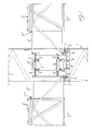
- 1 denotes a metal load-bearing pillar and 2 denotes four beams which are cross-fastened to said pillar.
- Metal angle-pieces are welded in the zone of the pillar 1 where the beams 2 are placed and supported, along the internal perimeter of the pillar 1.
- the flanges of these angle-pieces 3 projecting in the manner of a bracket towards the inside of the pillar 1 are provided with threaded through-holes inside which bolts 4 provided with a counter-nut 5, intended for the purposes described below, are screwed.
- Beam sections 2' are mounted in a telescopically slidable manner inside the beams 2.
- the beam sections 2' have welded (or otherwise fastened) at their end four bolts 6 and have welded on their underside a strip member 7 with a thickness such as to raise the support base of these beams to the same level as the bottom part 2" of the beams 2.
- the strip members 7 are arranged on the ends of pairs of bolts 4 which, by means of screwing or unscrewing, allow perfect levelling adjustment of the beams 2',2.
- the beams 2 have on their upper side strip members 2"' which have the purpose of guiding the beam sections 2' so as to limit any heightwise play of the telescopic beam sections 2'.
- the beams and pylon may be provided with suitable disposable formwork for containing the casting, forming valid elements for reducing the energy consumption.
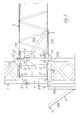
- an angular support 9 formed by a bracket 109 and a pair of tie-rods 209 is provided.
- This bracket 109 is hinged on the pylon 1 by means of a pin 10 which allows rotation thereof towards said pylon 1 through about 90°.
- This support 9 is shown, on the left of the pylon when viewing the figure, in the lowered position and, on the right and frontally with respect to the pylon, in a position rotated upwards with the bracket 9 horizontal.
- each tie-rod 209 has a pin 11 for positioning against the wall of the pylon 1 (see the bracket 9 shown on the right of this pylon 1).
- tie-rods 209 of each support 9 are fixed to the pylon 1 by means of the pins 13.
- the beam 2 instead is placed on the bracket 109 once the support 9 is in the operative position, i.e. rotated through 90° upwards and with this bracket in the horizontal position.
- This beam 109 may be placed on this bracket 109 in a position at a varying distance from the pylon 1 and is fixed thereto by means of adjustable pins 12 which - see for example the pin 12' - have a stem 112 with a certain length and are provided between the beam 2 and the pylon 1 with a pair of nuts 212 which allow a certain adjustment of the length thereof, i.e. the distance between beam 2 and pylon 1.
- the telescopic feature of the present beam is therefore, in this constructional variant, achieved by means of variable distance positioning of said beam 2 on said bracket.
Abstract
Method for using standard-length metal beams (pre-assembled reinforcement) over variable spans for mixed steel/concrete structures, in which the individual main beams (2) are associated with relatively short beam sections (2') or with bracket-type supports (9) and are able to slide telescopically with respect to these sections (2') or, by means of these supports (9), to be positioned at variable distances with respect to a supporting pillar beam (1); these beam sections (2') and/or these supports (9) are provided at the end with means (6, 8, 11, 13) for rapidly securing them to the pillar beam (1) and/or to the opposite beam section (2').
Description
- The present invention relates to metal load-bearing beams and columns for mixed steel/concrete structures and envisages suitable confinement of the critical sections of the reinforced-concrete structures by means of the provision of a closed section such as that shown in the accompanying drawings.
- In order to speed up the operations and reduce the costs, these metal beams are normally prefabricated.
- However, one of the drawbacks of these prefabricated beams consists in the fact that rarely do they have the exact length required at the working location. Therefore, their length must be modified on-site, which is not always easy and in any case results in a considerable amount of additional labour which also greatly increases the costs.
- The object of the present invention is therefore to devise a method for adapting beams on-site in an easy and rapid manner as well as provide a metal telescopic beam for implementing this method.
- This object is achieved by the present invention by means of a method for modifying on-site the length of metal beams for mixed steel/concrete structures, characterized in that the individual main beams are associated with relatively short beam sections or with bracket-type supports and are able to slide telescopically with respect to said sections or, by means of said supports rigidly connected to and hinged with the vertical structure forming the core of the columns, are able to be positioned at variable distances with respect to the support pillar; said beam sections and/or said supports are provided at the end with means for rapidly securing them to the pillar and/or to the opposite beam section.
- The pillars are designed to form a robust and stable framework able to ensure rapid and secure assembly and support their own weight and the weight of the cast concrete for completing the structure, so as to obtain a mixed steel/concrete structure which also has a suitable fire-resistance.
- Further characteristic features and advantages of the present invention will emerge more clearly from the following description of a preferred embodiment thereof, provided with reference to the accompanying drawings, in which:
- Figure 1 is a longitudinally sectioned view of a pillar able to support four beams according to a first embodiment of the invention;
- Figure 2 is a schematic perspective view of the same pillar with the four beams according to the invention;
- Figure 3 is a longitudinally sectioned view of a variant of the present beam where adaptation of the centre-to-centre distance of the standard beams and columns is performed by means of standard-length support brackets with suitable dimensions.
- With reference to the drawings and with particular reference to Figure 1 thereof, 1 denotes a metal load-bearing pillar and 2 denotes four beams which are cross-fastened to said pillar. Metal angle-pieces are welded in the zone of the
pillar 1 where thebeams 2 are placed and supported, along the internal perimeter of thepillar 1. The flanges of these angle-pieces 3 projecting in the manner of a bracket towards the inside of thepillar 1 are provided with threaded through-holes inside whichbolts 4 provided with a counter-nut 5, intended for the purposes described below, are screwed. - Beam sections 2' are mounted in a telescopically slidable manner inside the
beams 2. - The beam sections 2' have welded (or otherwise fastened) at their end four
bolts 6 and have welded on their underside astrip member 7 with a thickness such as to raise the support base of these beams to the same level as thebottom part 2" of thebeams 2. - The
strip members 7 are arranged on the ends of pairs ofbolts 4 which, by means of screwing or unscrewing, allow perfect levelling adjustment of thebeams 2',2. - 8 denotes tubular sleeves which are threaded at both ends and which are screwed onto the ends of the
nuts 6 so as to connect rigidly by means of screwing the opposite pairs ofbeams 2,2'. - The
beams 2 have on their upperside strip members 2"' which have the purpose of guiding the beam sections 2' so as to limit any heightwise play of the telescopic beam sections 2'. - The operating principle of the beam described according to this first embodiment of the invention will be evident.
- By means of telescopic extraction of the sections 2', the span of the
beam 2 is completed and the latter is fastened to thepylon 1. By means of rotation of the threaded sleeves 8, the two opposite sections 2', 2' are rigidly connected together. By means of adjustment of thebolts 4, the support points of thebeams 2 on thepylon 1 are adjusted. - At this point, the beams and pylon may be provided with suitable disposable formwork for containing the casting, forming valid elements for reducing the energy consumption.
- As an alternative to the sections 2' described above (see Figure 3 of the accompanying drawings) an
angular support 9 formed by abracket 109 and a pair of tie-rods 209 is provided. Thisbracket 109 is hinged on thepylon 1 by means of apin 10 which allows rotation thereof towards saidpylon 1 through about 90°. Thissupport 9 is shown, on the left of the pylon when viewing the figure, in the lowered position and, on the right and frontally with respect to the pylon, in a position rotated upwards with thebracket 9 horizontal. At the free end each tie-rod 209 has apin 11 for positioning against the wall of the pylon 1 (see thebracket 9 shown on the right of this pylon 1). These tie-rods 209 of eachsupport 9 are fixed to thepylon 1 by means of thepins 13. Thebeam 2 instead is placed on thebracket 109 once thesupport 9 is in the operative position, i.e. rotated through 90° upwards and with this bracket in the horizontal position. Thisbeam 109 may be placed on thisbracket 109 in a position at a varying distance from thepylon 1 and is fixed thereto by means ofadjustable pins 12 which - see for example the pin 12' - have astem 112 with a certain length and are provided between thebeam 2 and thepylon 1 with a pair ofnuts 212 which allow a certain adjustment of the length thereof, i.e. the distance betweenbeam 2 andpylon 1. The telescopic feature of the present beam is therefore, in this constructional variant, achieved by means of variable distance positioning of saidbeam 2 on said bracket. - Obviously the present invention is not limited to the embodiment shown and described, but comprises all those variants and modifications which fall within the scope of the inventive idea, substantially as claimed below.
Claims (8)
- Method for using standard-length metal beams (pre-assembled reinforcement) over variable spans for mixed steel/concrete structures, in which the individual main beams (2) are associated with relatively short beam sections (2') or with bracket-type supports (9) and are able to slide telescopically with respect to said sections (2') or, by means of said supports (9), to be positioned at variable distances with respect to a supporting pillar beam (1), said beam sections (2') and/or said supports (9) being provided at the end with means (6, 8, 11, 13) for rapidly securing them to the pillar beam (1) and/or to the opposite beam section (2').
- Method according to Claim 1, characterized in that metal angle-pieces (3) are secured in the zone of the pillar (1) for supporting the beams (2, 2'), along the internal perimeter of the pillar (1), the flanges of said angle-pieces, which projecting in the manner of a bracket towards the inside of the pillar (1), being provided with threaded through-holes inside which bolts (4) forming adjustable support elements for the ends of the beams (2,2') are screwed.
- Method according to the preceding Claims 1 and 2, characterized in that the beam sections (2') have, welded at the end, bolts (6) and have welded on their bottom side a spacing strip member (7).
- Method according to Claim 3, characterized in that the said strip members (7) rest on the ends of the pairs of bolts (4) which, by means of screwing or unscrewing, allow perfect levelling adjustment of the beams (2',2).
- Method according to any one of the preceding claims, characterized in that tubular sleeves (8) which are threaded at both ends are envisaged, being screwed onto the ends of the nuts (6), so as to connect rigidly by means of screwing thereof the opposite pairs of beams (2,2').
- Metal beam for mixed steel/concrete structures, characterized in that it comprises two beam elements (2, 2') which are mounted slidably relative to each other in a telescopic manner and are provided with means (6, 8) for rigidly connecting them to a pillar (1) and/or to an opposite beam structure.
- Metal beam according to Claim 1, characterized in that said support (9) comprises a bracket (109) which is hinged via means (10) which allow a certain rotation thereof with respect to the pillar (1) and a tie-rod (209) fixed by suitable means (11, 13) to said pillar (1), the beam (2) being able to rest on said bracket (109) and be fixed to the pillar (1) at a variable distance.
- Metal beam according to Claim 7, characterized in that the beam (2) is rested on the bracket (109) and fixed to the pillar (1) by means of the adjustable-length pins (12, 12') able to be fixed to the wall of the pillar (1) so as to arrange said beam at a varying distance from the pillar (1).
Applications Claiming Priority (1)
| Application Number | Priority Date | Filing Date | Title |
|---|---|---|---|
| ITGE20060108 ITGE20060108A1 (en) | 2006-11-15 | 2006-11-15 | METHOD FOR THE PREFABRICATION OF METAL BEAMS OF BEAMS AND COLUMNS FOR MIXED STRUCTURES STEEL-CONCRETE OF LUNGHEZZESTANDARD WITH POSSIBILITY OF USE ON LIGHTS HIGHER THAN THE BEAMS OF THE SAME. |
Publications (1)
| Publication Number | Publication Date |
|---|---|
| EP1925757A1 true EP1925757A1 (en) | 2008-05-28 |
Family
ID=39102988
Family Applications (1)
| Application Number | Title | Priority Date | Filing Date |
|---|---|---|---|
| EP07119729A Withdrawn EP1925757A1 (en) | 2006-11-15 | 2007-10-31 | Method for prefabricating the metal reinforcement of beams and columns for standard-length mixed steel/concrete structures and a telescopic beam |
Country Status (2)
| Country | Link |
|---|---|
| EP (1) | EP1925757A1 (en) |
| IT (1) | ITGE20060108A1 (en) |
Cited By (4)
| Publication number | Priority date | Publication date | Assignee | Title |
|---|---|---|---|---|
| CN107190854A (en) * | 2017-06-21 | 2017-09-22 | 长沙三远钢结构有限公司 | Heavy wall insertion box steel column node |
| CN107724688A (en) * | 2017-11-20 | 2018-02-23 | 中国二冶集团有限公司 | A kind of beam muscle colligation auxiliary stand |
| US10378199B2 (en) * | 2014-07-07 | 2019-08-13 | Fundacion Tecnalia Research and Innovation | Dry joint joining device between columns and beams of precast reinforced concrete |
| CN113389276A (en) * | 2021-07-23 | 2021-09-14 | 东莞市联泰钢构有限公司 | Light-duty assembled steel construction building |
Citations (8)
| Publication number | Priority date | Publication date | Assignee | Title |
|---|---|---|---|---|
| BE561298A (en) * | ||||
| US2726743A (en) | 1951-05-21 | 1955-12-13 | Robert J Short | Telescoped open web beam construction |
| BE701007A (en) * | 1966-03-23 | 1967-12-18 | ||
| GB1400595A (en) | 1971-11-23 | 1975-07-16 | Dowsett Eng Australia Pty Ltd | Interconnecting structural elements |
| GB2027785A (en) | 1978-08-14 | 1980-02-27 | Camazet Ag | A Connection Between a Beam or Beams and a Pillar, all of Prefabricated Concrete |
| FR2466576A1 (en) | 1979-10-03 | 1981-04-10 | Saret | Beam to column joint concrete frame - uses steel column sleeve for welded beam end bracket and sleeve grooves form shear key in site concrete |
| GB2149874A (en) | 1983-09-22 | 1985-06-19 | Norcros Investments Ltd | Building structure |
| WO1988008059A1 (en) | 1987-04-07 | 1988-10-20 | østspenn Holding A/S | Building construction |
-
2006
- 2006-11-15 IT ITGE20060108 patent/ITGE20060108A1/en unknown
-
2007
- 2007-10-31 EP EP07119729A patent/EP1925757A1/en not_active Withdrawn
Patent Citations (8)
| Publication number | Priority date | Publication date | Assignee | Title |
|---|---|---|---|---|
| BE561298A (en) * | ||||
| US2726743A (en) | 1951-05-21 | 1955-12-13 | Robert J Short | Telescoped open web beam construction |
| BE701007A (en) * | 1966-03-23 | 1967-12-18 | ||
| GB1400595A (en) | 1971-11-23 | 1975-07-16 | Dowsett Eng Australia Pty Ltd | Interconnecting structural elements |
| GB2027785A (en) | 1978-08-14 | 1980-02-27 | Camazet Ag | A Connection Between a Beam or Beams and a Pillar, all of Prefabricated Concrete |
| FR2466576A1 (en) | 1979-10-03 | 1981-04-10 | Saret | Beam to column joint concrete frame - uses steel column sleeve for welded beam end bracket and sleeve grooves form shear key in site concrete |
| GB2149874A (en) | 1983-09-22 | 1985-06-19 | Norcros Investments Ltd | Building structure |
| WO1988008059A1 (en) | 1987-04-07 | 1988-10-20 | østspenn Holding A/S | Building construction |
Cited By (4)
| Publication number | Priority date | Publication date | Assignee | Title |
|---|---|---|---|---|
| US10378199B2 (en) * | 2014-07-07 | 2019-08-13 | Fundacion Tecnalia Research and Innovation | Dry joint joining device between columns and beams of precast reinforced concrete |
| CN107190854A (en) * | 2017-06-21 | 2017-09-22 | 长沙三远钢结构有限公司 | Heavy wall insertion box steel column node |
| CN107724688A (en) * | 2017-11-20 | 2018-02-23 | 中国二冶集团有限公司 | A kind of beam muscle colligation auxiliary stand |
| CN113389276A (en) * | 2021-07-23 | 2021-09-14 | 东莞市联泰钢构有限公司 | Light-duty assembled steel construction building |
Also Published As
| Publication number | Publication date |
|---|---|
| ITGE20060108A1 (en) | 2008-05-16 |
Similar Documents
| Publication | Publication Date | Title |
|---|---|---|
| KR102229170B1 (en) | A panel support bracket | |
| US4036466A (en) | Flying deck-type concrete form installation | |
| EP1925757A1 (en) | Method for prefabricating the metal reinforcement of beams and columns for standard-length mixed steel/concrete structures and a telescopic beam | |
| CN107975251B (en) | Assembled building wallboard joint support device | |
| CN106978904A (en) | A kind of lattice column locating guide device and the technique constructed using locating guide device | |
| CN212715972U (en) | Prefabricated bed-jig suitable for multiple specification pier stud reinforcing bar | |
| KR200436819Y1 (en) | System form for constructing beam | |
| CN215482366U (en) | Double-line continuous beam bracket structure | |
| CN115679834A (en) | Construction method for variable-section special-shaped cable tower pulling-supporting combined temporary consolidation mid-tower column | |
| CN206016305U (en) | Viscous damping wall integration support system | |
| CN114717968A (en) | Construction method for main tower of cable-stayed bridge | |
| KR100933047B1 (en) | Formwork system for concrete slab of filled steel pipe girder bridge | |
| CN205296821U (en) | Oblique roofing formwork system of heavy grade cast in situ concrete | |
| RU2383701C2 (en) | Mobile scaffolding | |
| CN109629447B (en) | Variable cross-section cast-in-situ box girder construction and concrete pouring method | |
| CN210684479U (en) | Concrete cast-in-place support of adjustable slope | |
| KR100933045B1 (en) | Formwork system for concrete slab of filled steel pipe girder bridge | |
| NL1025588C1 (en) | Table moulding for forming edges of concrete floor, has hook with telescopic arms and sliding weight for supporting it when being lifted by crane to floor above | |
| CN213804941U (en) | Variable cross section day style of calligraphy empty stomach thin wall mound reinforcing bar subregion prefabricated bed-jig | |
| JPH0932283A (en) | Beam form | |
| AU2003200719A1 (en) | Cast in plates | |
| CN215484130U (en) | Prefabricated parapet | |
| CN214116704U (en) | Suspended cast-in-situ caisson cabin top separation plate structure | |
| CN111608691B (en) | Shield working well template support construction method | |
| JP2004232214A (en) | Bridge floor slab supporting form and work execution method for bridge floor slab using this form |
Legal Events
| Date | Code | Title | Description |
|---|---|---|---|
| PUAI | Public reference made under article 153(3) epc to a published international application that has entered the european phase |
Free format text: ORIGINAL CODE: 0009012 |
|
| AK | Designated contracting states |
Kind code of ref document: A1 Designated state(s): AT BE BG CH CY CZ DE DK EE ES FI FR GB GR HU IE IS IT LI LT LU LV MC MT NL PL PT RO SE SI SK TR |
|
| AX | Request for extension of the european patent |
Extension state: AL BA HR MK RS |
|
| 17P | Request for examination filed |
Effective date: 20081024 |
|
| AKX | Designation fees paid |
Designated state(s): DE FR IT |
|
| STAA | Information on the status of an ep patent application or granted ep patent |
Free format text: STATUS: THE APPLICATION IS DEEMED TO BE WITHDRAWN |
|
| 18D | Application deemed to be withdrawn |
Effective date: 20100501 |