EP1925753A2 - Rail-road excavator. - Google Patents
Rail-road excavator. Download PDFInfo
- Publication number
- EP1925753A2 EP1925753A2 EP07018297A EP07018297A EP1925753A2 EP 1925753 A2 EP1925753 A2 EP 1925753A2 EP 07018297 A EP07018297 A EP 07018297A EP 07018297 A EP07018297 A EP 07018297A EP 1925753 A2 EP1925753 A2 EP 1925753A2
- Authority
- EP
- European Patent Office
- Prior art keywords
- way
- traverse
- wheels
- excavator according
- axles
- Prior art date
- Legal status (The legal status is an assumption and is not a legal conclusion. Google has not performed a legal analysis and makes no representation as to the accuracy of the status listed.)
- Withdrawn
Links
Images
Classifications
-
- E—FIXED CONSTRUCTIONS
- E02—HYDRAULIC ENGINEERING; FOUNDATIONS; SOIL SHIFTING
- E02F—DREDGING; SOIL-SHIFTING
- E02F9/00—Component parts of dredgers or soil-shifting machines, not restricted to one of the kinds covered by groups E02F3/00 - E02F7/00
- E02F9/02—Travelling-gear, e.g. associated with slewing gears
- E02F9/022—Travelling-gear, e.g. associated with slewing gears for moving on rails
-
- B—PERFORMING OPERATIONS; TRANSPORTING
- B60—VEHICLES IN GENERAL
- B60F—VEHICLES FOR USE BOTH ON RAIL AND ON ROAD; VEHICLES CAPABLE OF TRAVELLING IN OR ON DIFFERENT MEDIA, e.g. AMPHIBIOUS VEHICLES
- B60F1/00—Vehicles for use both on rail and on road; Conversions therefor
- B60F1/04—Vehicles for use both on rail and on road; Conversions therefor with rail and road wheels on different axles
- B60F1/043—Vehicles comprising own propelling units
-
- B—PERFORMING OPERATIONS; TRANSPORTING
- B60—VEHICLES IN GENERAL
- B60F—VEHICLES FOR USE BOTH ON RAIL AND ON ROAD; VEHICLES CAPABLE OF TRAVELLING IN OR ON DIFFERENT MEDIA, e.g. AMPHIBIOUS VEHICLES
- B60F2301/00—Retractable wheels
- B60F2301/04—Retractable wheels pivotally
Definitions
- the invention relates to a two-way excavator according to the preamble of claim 1.
- two-way excavator which have an undercarriage with at least two axles with wheels for road travel and two pivotable in operating position axles with wheels for rail travel.
- the wheels for rail travel each have two mounted in a mounting frame swing, which are pivotable about hydraulic cylinder about a pivot point.
- Such two-way excavators are multifunctional use.
- they are roadworthy as wheeled vehicles like a conventional wheeled excavator and can drive independently and independently to their place of use.
- the two-way excavator can be converted into a rail vehicle in a very simple manner become.
- the drive is provided by the driven road wheels, which roll on the rail.
- the leadership of the two-way tiller takes place via the rail wheels.
- the object of the invention is therefore to develop a generic two-way excavator such that it can be converted from a two-way excavator with rigid axles in an easy way in a two-way excavator with swing axle.
- the object is achieved by the combination of the features of claim 1. Accordingly, the two mounted in a mounting frame rockers, which carry the pivotable axle with the wheels for rail travel either via a crossbar rigidly connected to each other. Here, therefore, by inserting and connecting to the traverse the respectively the axis overlapping wings are rigidly connected together if necessary.
- a two-way excavator can be designed for transport on the rails with two pendulum axles and, if required, can then be used by a simple handle, the traverse between the wings and connected to the wings.
- the traverse may consist of a closed at each of their ends tube, which is each rigidly connected to the adjacent rocker. Due to the design as a tube, the total weight of the traverse can be kept low with sufficiently high strength. Only the end areas with which the traverse forming tube is closed, must be made of a solid material.
- the rigid connection can be made via a screw connection.
- This screw can be done via laterally introduced from the outside into the rocker screws, which are screwed into a corresponding provided in the end regions of the crossbar thread.
- the traverse can be received in each case with its ends form-fitting manner in the rocker.
- the positive reception can consist in a swing-side slot, in which the end portions of the crosshead, which are shaped according to the shape of the slot, are inserted.
- At least one handle is formed on the crossbar.
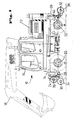
- a two-way excavator 10 is shown, which in the usual way an upper carriage 12 with the driver's cab 16 and a cultivated working tool 18 - here in the form of a spoon attached to a spoon - has.
- the undercarriage 14 has two axles 20 and 22, which are each equipped with twin wheels 16, 18 for road travel.
- the axis 20 is designed as a rigid axle, while the axis 22 is a steered axle.
- attachments 24 and 26 are arranged at both free ends, that is to say at the front and at the rear side of the undercarriage 14, which additionally carry pivotable axes 30 and 32 about pivot points 28.
- the axles 30 and 32 in turn carry wheels 34 and 36 for rail travel.
- the axles 30 and 32 are pivoted respectively via hydraulic cylinders 38 and 40 from a retracted position to a disengaged position in which the axles 20 and 22 are excavated.
- the axes 30 and 32 are shown in partially retracted position, wherein at the front of the two-way hanger 10, the axis 30 is shown in a partially raised position and in a fully pivoted position.
- the pivot radius is located.
- the two-way excavator 10 is ready for driving on the road.
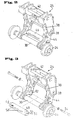
- FIGS. 2 and 3 show details of the attachment 24, which apply in the same way for the attachment 26.
- a mounting frame 42 which can be connected to the undercarriage 14 according to FIG. 1, is shown, which in each case has rockers 44 pivotable laterally about pivot points 28.
- the rockers 44 consist of almost L-shaped sheets, which are pivotable about hydraulic cylinders 38 about the respective pivot points 28.
- the respective axis 30 is mounted.
- a wheel for rail travel 34 is rotatably mounted in each case at its free end.
- the attachments 24 are each shown in a different setup state.
- the axis 30 is designed as a rigid axle, while it is designed in Figure 3 as a pendulum axis. This is due to the fact that in the embodiment according to FIG. 2, the two rockers 44 are firmly connected to one another via a cross member 46. The traverse 46 connects the two wings 44 approximately at the vertex of the L-shaped plates.
- the cross member 46 consists of a tube 48 and two end closure parts 50. These can be made of solid material.
- the outer shape of the closure members 50 may, as shown in the embodiment of Figure 3, be adapted to corresponding provided on the side walls of the rockers 44 slots 52.
- the traverse 48 can be easily inserted into the respective slots 52 in the area of the rockers 44 via their end regions 50.
- To attach the crossbar serve mounting screws 54 which are screwed into associated threaded holes 56 in the end 50 of the cross member 46.
- two handles 58 are formed in the embodiment according to Figures 2 and 3.
- the traverse 46 can be easily connected to the two wings 44, so that a conversion of a pendulum axis 30 of Figure 3 in a rigid axle according to Figure 2 and vice versa in a simple manner is possible.
Landscapes
- Engineering & Computer Science (AREA)
- Mining & Mineral Resources (AREA)
- Civil Engineering (AREA)
- General Engineering & Computer Science (AREA)
- Structural Engineering (AREA)
- Transportation (AREA)
- Mechanical Engineering (AREA)
- Machines For Laying And Maintaining Railways (AREA)
- Agricultural Machines (AREA)
- Handcart (AREA)
Abstract
Die vorliegende Erfindung betrifft einen Zweiwegebagger (10) mit einem Unterwagen (14) mit mindestens zwei Achsen (20,22) mit Rädern für die Straßenfahrt und zwei in Betriebsposition schwenkbaren Achsen (30,32) mit Rädern (34,36) für die Schienenfahrt, die jeweils über zwei in einem Anbaurahmen gelagerte Schwingen (44), die über Hydraulikzylinder (38,40) um einen Schwenkpunkt (28) verschwenkbar gelagert sind, wobei die Schwingen wahlweise über eine Traverse (46) starr miteinander verbindbar sind.The present invention relates to a two-way excavator (10) with an undercarriage (14) with at least two axles (20,22) with wheels for road travel and two pivotable in operating position axles (30,32) with wheels (34,36) for rail travel , which in each case via two mounted in a mounting frame rockers (44) which are pivotally mounted about hydraulic cylinder (38,40) about a pivot point (28), wherein the rockers are selectively connected via a crossbar (46) rigidly connected.
Description
Die Erfindung betrifft einen Zweiwegebagger nach dem Oberbegriff des Anspruchs 1.The invention relates to a two-way excavator according to the preamble of claim 1.
Es sind bereits Zweiwegebagger bekannt, die einen Unterwagen mit mindestens zwei Achsen mit Rädern für die Straßenfahrt und zwei in Betriebsposition schwenkbaren Achsen mit Rädern für die Schienenfahrt aufweisen. Die Räder für die Schienenfahrt weisen jeweils über zwei in einem Anbaurahmen gelagerte Schwingen auf, die über Hydraulikzylinder um einen Schwenkpunkt verschwenkbar sind. Derartige Zweiwegebagger sind multifunktional einsetzbar. Zum einen sind sie wie ein üblicher Mobilbagger als Radfahrzeug straßentauglich und können unabhängig und eigenständig zu ihrem Einsatzort fahren. Durch entsprechendes Ausfahren der mit den Rädern für die Schienenfahrt ausgestatteten Achsen kann der Zweiwegebagger in sehr einfacher Art und Weise zu einem Schienenfahrzeug umfunktioniert werden. Der Antrieb erfolgt durch die angetriebenen Straßenräder, die auf der Schiene abrollen. Die Führung des Zweiwegebaggers dagegen erfolgt über die Schienenräder.There are already known two-way excavator, which have an undercarriage with at least two axles with wheels for road travel and two pivotable in operating position axles with wheels for rail travel. The wheels for rail travel each have two mounted in a mounting frame swing, which are pivotable about hydraulic cylinder about a pivot point. Such two-way excavators are multifunctional use. On the one hand, they are roadworthy as wheeled vehicles like a conventional wheeled excavator and can drive independently and independently to their place of use. By appropriately extending the axes equipped with the wheels for rail travel, the two-way excavator can be converted into a rail vehicle in a very simple manner become. The drive is provided by the driven road wheels, which roll on the rail. The leadership of the two-way tiller, however, takes place via the rail wheels.
Grundsätzlich ist es bekannt, die zusätzliche Achsenaufnahme der Räder für die Schienenfahrt als pendelnde Achse oder als Starrachse auszuführen. Jede dieser Anordnungen hat spezifische Vorteile. Während die Starrachse eine höhere Stabilität aufweist, fordert diese allerdings sehr gleichmäßig verlegte Schienen für eine ruhige Fahrt des Zweiwegebaggers auf dem Schienenstrang. Dagegen muss eine gute Anpassung an einen vergleichsweise schlechtere Schienensituation, wie sie durch eine Pendellagerung der Achse erzielt wird, mit einer vergleichsweise schlechteren Stabilität während des Einsatzes des Zweiwegebaggers auf der Schiene erkauft werden.In principle, it is known to carry out the additional axle mounting of the wheels for rail travel as a swinging axle or as a rigid axle. Each of these arrangements has specific advantages. While the rigid axle has a higher stability, but this requires very evenly laid rails for a quiet ride of the two-way truck on the rail track. In contrast, a good adaptation to a comparatively worse rail situation, as achieved by a pendulum bearing of the axle, with a comparatively poorer stability during the use of the two-way tiller on the rail must be bought.
Aufgabe der Erfindung ist es daher, einen gattungsgemäßen Zweiwegebagger derart weiterzubilden, dass er sich von einem Zweiwegebagger mit Starrachsen in leichter Weise in einen Zweiwegebagger mit Pendelachse umrüsten lässt.The object of the invention is therefore to develop a generic two-way excavator such that it can be converted from a two-way excavator with rigid axles in an easy way in a two-way excavator with swing axle.
Erfindungsgemäß wird die Aufgabe durch die Kombination der Merkmale des Anspruchs 1 gelöst. Demnach sind die zwei in einem Anbaurahmen gelagerten Schwingen, die die schwenkbare Achse mit den Rädern für die Schienenfahrt tragen wahlweise über eine Traverse starr miteinander verbindbar. Hier werden also durch ein Einschieben und Verbinden mit der Traverse die jeweils die Achse lagernden Schwingen bei Bedarf starr miteinander verbunden. So kann ein Zweiwegebagger zum Transport auf den Schienen mit zwei Pendelachsen ausgebildet sein und bei entsprechendem Bedarf kann dann durch einen einfachen Handgriff die Traverse zwischen den Schwingen eingesetzt werden und mit den Schwingen verbunden werden.According to the invention the object is achieved by the combination of the features of claim 1. Accordingly, the two mounted in a mounting frame rockers, which carry the pivotable axle with the wheels for rail travel either via a crossbar rigidly connected to each other. Here, therefore, by inserting and connecting to the traverse the respectively the axis overlapping wings are rigidly connected together if necessary. Thus, a two-way excavator can be designed for transport on the rails with two pendulum axles and, if required, can then be used by a simple handle, the traverse between the wings and connected to the wings.
Besondere Ausgestaltungen der Erfindung ergeben sich aus den sich an den Hauptanspruch anschließenden Unteransprüchen.Particular embodiments of the invention will become apparent from the subsequent claims to the main claim.
Demnach kann die Traverse aus einem an ihren Enden jeweils geschlossenem Rohr bestehen, das jeweils starr mit der anliegenden Schwinge verbunden ist. Durch die Ausführung als Rohr kann das Gesamtgewicht der Traverse bei hinreichend hoher Festigkeit gering gehalten werden. Lediglich die Endbereiche, mit denen das die Traverse bildende Rohr verschlossen wird, müssen aus einem massiven Material gefertigt werden.Accordingly, the traverse may consist of a closed at each of their ends tube, which is each rigidly connected to the adjacent rocker. Due to the design as a tube, the total weight of the traverse can be kept low with sufficiently high strength. Only the end areas with which the traverse forming tube is closed, must be made of a solid material.
Vorzugsweise kann die starre Verbindung über eine Schraubverbindung erfolgen. Diese Schraubverbindung kann über seitlich von außen in die Schwinge eingeführte Schrauben erfolgen, die in ein entsprechendes in den Endbereichen der Traverse vorgesehenes Gewinde eingeschraubt werden.Preferably, the rigid connection can be made via a screw connection. This screw can be done via laterally introduced from the outside into the rocker screws, which are screwed into a corresponding provided in the end regions of the crossbar thread.
Vorteilhaft kann die Traverse jeweils mit ihren Enden formschlüssig in den Schwingen aufgenommen sein.Advantageously, the traverse can be received in each case with its ends form-fitting manner in the rocker.
Die formschlüssige Aufnahme kann in einem schwingenseitigen Schlitz bestehen, in den die Endbereiche der Traverse, die entsprechend der Formgebung des Schlitzes formangepaßt sind, einschiebbar sind.The positive reception can consist in a swing-side slot, in which the end portions of the crosshead, which are shaped according to the shape of the slot, are inserted.
Zur leichteren Handhabbarkeit ist an der Traverse zumindest ein Handgriff angeformt.For ease of handling at least one handle is formed on the crossbar.
Weitere Merkmale, Einzelheiten und Vorteile der Erfindung werden anhand eines in der Zeichnung dargestellten Ausführungsbeispiels erläutert. Es zeigen:
- Figur 1:
- eine Seitenansicht eines Zweiwebebaggers nach einer Ausführungsform der vorliegenden Erfindung,
- Figur 2:
- eine perspektivische Detailansicht eines Teils des Zweiwegebaggers gemäß Figur 1 und
- Figur 3:
- eine Darstellung gemäß Figur 2, bei der ein entfernbares Bauteil explosionsartig auseinandergezogen ist.
- FIG. 1:
- a side view of a two-web rapier according to an embodiment of the present invention,
- FIG. 2:
- a detailed perspective view of a portion of the two-way hanger according to Figure 1 and
- FIG. 3:
- a view according to Figure 2, in which a removable component is exploded exploded.
In Figur 1 ist ein Zweiwegebagger 10 dargestellt, der in üblicher Weise einen Oberwagen 12 mit Fahrerkabine 16 und ein angebautes Arbeitswerkzeug 18 - hier in Form eines an einen Löffelstiel angesetzten Löffels - aufweist. Der Unterwagen 14 weist zwei Achsen 20 und 22 auf, die jeweils mit Zwillingsrädern 16, 18 für die Straßenfahrt ausgerüstet sind. Dabei ist die Achse 20 als Starrachse ausgelegt, während die Achse 22 eine gelenkte Achse ist.In Figure 1, a two-
Wie es schon bei Zweiwegebaggern als solches bekannt ist, sind an beiden freien Enden, also an der Vorderseite und an der Hinterseite des Unterwagens 14 Anbauten 24 und 26 angeordnet, die zusätzlich um Schwenkpunkte 28 schwenkbare Achsen 30 und 32 tragen. Die Achsen 30 und 32 tragen wiederum Räder 34 und 36 für die Schienenfahrt. Die Achsen 30 und 32 sind jeweils über Hydraulikzylinder 38 bzw. 40 von einer eingefahrenen Stellung in eine Aushebestellung, in der die Achsen für die Straßenfahrt 20 und 22 ausgehoben sind, verschwenkbar. In der Figur 1 sind die Achsen 30 und 32 in teilweise eingefahrener Position gezeigt, wobei an der Vorderseite des Zweiwegebaggers 10 die Achse 30 in einer teilweise hochgeschwenkten Position und in einer vollständig hochgeschwenkten Position gezeigt ist. Hierzu ist der Schwenkradius eingezeichnet. In der Darstellung gemäß Figur 1 ist der Zweiwegebagger 10 für die Straßenfahrt bereit.As is already known as such with two-way dredgers,
Die Figuren 2 und 3 zeigen Details des Anbaus 24, die in gleicher Weise für den Anbau 26 gelten. Hier ist jeweils ein mit dem Unterwagen 14 gemäß Figur 1 verbindbarer Anbaurahmen 42 gezeigt, der jeweils seitlich um Schwenkpunkte 28 verschwenkbare Schwingen 44 aufweist. Die Schwingen 44 bestehen aus nahezu L-förmigen Blechen, die über Hydraulikzylinder 38 um die jeweiligen Schwenkpunkte 28 verschwenkbar sind. An den freien Enden der Schwingen 44 ist die jeweilige Achse 30 gelagert. Auf dieser ist jeweils an ihrem freien Ende ein Rad für die Schienenfahrt 34 drehend gelagert.Figures 2 and 3 show details of the
In den Figuren 2 und 3 sind die Anbauten 24 jeweils in einem unterschiedlichen Rüstzustand gezeigt. In der Darstellung gemäß Figur 2 ist die Achse 30 als Starrachse ausgeführt, während sie in Figur 3 als Pendelachse ausgeführt ist. Dies hängt damit zusammen, dass in der Ausführungsform gemäß Figur 2 die beiden Schwingen 44 über eine Traverse 46 fest miteinander verbunden sind. Die Traverse 46 verbindet die beiden Schwingen 44 ungefähr an dem Eckpunkt der L-förmigen Bleche.In Figures 2 and 3, the
In Figur 3 ist die Traverse 46 zwischen den Schwingen 44 entfernt, so dass die einzelnen Schwingen 44 frei pendeln können und so eine Pendelachse 30 am Anbau 24 ausgebildet ist.In Figure 3, the
Erfindungsgemäß besteht die Traverse 46 aus einem Rohr 48 und zwei endseitigen Verschlußteilen 50. Diese können aus jeweils massivem Material gefertigt sein. Die äußere Form der Verschlußteile 50 kann, wie hier im Ausführungsbeispiel gemäß Figur 3 gezeigt, an entsprechende an den Seitenwänden der Schwingen 44 vorgesehene Schlitze 52 angepaßt sein. Hierdurch lässt sich die Traverse 48 über Ihre Endbereiche 50 einfach in die jeweiligen Schlitze 52 im Bereich der Schwingen 44 einschieben. Zur Befestigung der Traverse dienen Befestigungsschrauben 54, die in zugehörige Gewindebohrungen 56 im Endbereich 50 der Traverse 46 einschraubbar sind. Zur entsprechenden Handhabung der Traverse sind in der Ausführungsform gemäß der Figuren 2 und 3 zwei Handgriffe 58 angeformt.According to the invention, the
Somit lässt sich in einfacher Weise die Traverse 46 mit den beiden Schwingen 44 verbinden, so dass eine Umrüstung von einer pendelnden Achse 30 gemäß Figur 3 in eine Starrachse gemäß Figur 2 und umgekehrt in einfacher Art und Weise möglich ist.Thus, the
Claims (6)
dadurch gekennzeichnet,
dass die Schwingen wahlweise über eine Traverse starr miteinander verbindbar sind.Two-way excavators with an undercarriage with at least two axles with wheels for road travel and two axles with wheels for rail travel which can be swiveled in operating position, which are each supported by two rockers mounted in a mounting frame, which are pivotable about a pivot point via hydraulic cylinders,
characterized,
that the wings are selectively connected via a crossbar rigidly.
Applications Claiming Priority (1)
| Application Number | Priority Date | Filing Date | Title |
|---|---|---|---|
| DE200620017726 DE202006017726U1 (en) | 2006-11-21 | 2006-11-21 | Two-way excavator |
Publications (2)
| Publication Number | Publication Date |
|---|---|
| EP1925753A2 true EP1925753A2 (en) | 2008-05-28 |
| EP1925753A3 EP1925753A3 (en) | 2009-12-16 |
Family
ID=39000680
Family Applications (1)
| Application Number | Title | Priority Date | Filing Date |
|---|---|---|---|
| EP07018297A Withdrawn EP1925753A3 (en) | 2006-11-21 | 2007-09-18 | Rail-road excavator. |
Country Status (2)
| Country | Link |
|---|---|
| EP (1) | EP1925753A3 (en) |
| DE (1) | DE202006017726U1 (en) |
Cited By (1)
| Publication number | Priority date | Publication date | Assignee | Title |
|---|---|---|---|---|
| CN103935285A (en) * | 2014-04-30 | 2014-07-23 | 四川森田消防装备制造有限公司 | Bidirectional-traveling road-rail dual-purpose multifunctional emergency rescuing fire fighting truck |
Family Cites Families (10)
| Publication number | Priority date | Publication date | Assignee | Title |
|---|---|---|---|---|
| US3269331A (en) * | 1964-01-30 | 1966-08-30 | Koehring Co | Convertible railway-highway vehicle |
| DE1530127A1 (en) * | 1966-01-20 | 1970-04-23 | Kalamazoo Mfg Company | Motor vehicle for locomotion on railroad tracks and other surfaces |
| US3653332A (en) * | 1970-02-12 | 1972-04-04 | Olson & Sons Inc Chas | Convertible rail-highway vehicle |
| US4534297A (en) * | 1982-12-02 | 1985-08-13 | Johnson Sr Theodore C | Wheel position control for railway maintenance vehicle |
| DE8428626U1 (en) * | 1984-09-28 | 1985-03-14 | Fischer, Hans-Jürgen, 8501 Großhabersdorf | PROTECTIVE DEVICE FOR OPEN FIREPLACES |
| DD258434A1 (en) * | 1987-03-09 | 1988-07-20 | Fortschritt Veb K | ADAPTER FOR MOTORCYCLES AND MOBIL CRANES |
| JP2562823Y2 (en) * | 1992-09-04 | 1998-02-16 | 新キャタピラー三菱株式会社 | Undercarriage of work vehicle |
| JP3579911B2 (en) * | 1993-10-30 | 2004-10-20 | コベルコ建機株式会社 | Track work machine |
| ES2243178T3 (en) * | 2000-08-10 | 2005-12-01 | Atlas Weyhausen Gmbh | PROCEDURE FOR THE SUPPORT OF A HYDRAULICALLY AND MOVABLE OPERATED WORK TEAM ON A RAILWAY, AS WELL AS WORK TEAM FOR THE PERFORMANCE OF THIS PROCEDURE. |
| US7201106B2 (en) * | 2002-03-18 | 2007-04-10 | Whiston Joseph L | Hydrostatic hi-rail system |
-
2006
- 2006-11-21 DE DE200620017726 patent/DE202006017726U1/en not_active Expired - Lifetime
-
2007
- 2007-09-18 EP EP07018297A patent/EP1925753A3/en not_active Withdrawn
Cited By (2)
| Publication number | Priority date | Publication date | Assignee | Title |
|---|---|---|---|---|
| CN103935285A (en) * | 2014-04-30 | 2014-07-23 | 四川森田消防装备制造有限公司 | Bidirectional-traveling road-rail dual-purpose multifunctional emergency rescuing fire fighting truck |
| CN103935285B (en) * | 2014-04-30 | 2015-11-18 | 四川森田消防装备制造有限公司 | A kind of two way rail dual-purpose multifunctional emergency rescue fire vehicle |
Also Published As
| Publication number | Publication date |
|---|---|
| EP1925753A3 (en) | 2009-12-16 |
| DE202006017726U1 (en) | 2008-04-03 |
Similar Documents
| Publication | Publication Date | Title |
|---|---|---|
| EP2192026B1 (en) | Agricultural traction engine | |
| EP1925754B1 (en) | Rail-road excavator | |
| DE3912194C2 (en) | vehicle | |
| EP2443285A1 (en) | Storage cart for transporting bulk goods | |
| WO2013064199A1 (en) | Road-rail vehicle | |
| DE202007018853U1 (en) | Dolly axle | |
| WO2020025201A1 (en) | Combination having a tractor and a semi-trailer, tractor, semi-trailer and method for axle load distribution in a combination | |
| EP2013041B1 (en) | Transportation device | |
| EP3468820B1 (en) | Construction machine, in particular a soil compacting machine, specifically a rubber-wheeled roller, method for operating a construction machine and method for producing a construction machine | |
| DE9001589U1 (en) | Crane vehicle | |
| DE60111711T2 (en) | Drawbar for a trailer | |
| DE102012001377B4 (en) | Ballast truck for a derrick crane | |
| DE102007044866A1 (en) | Two-way excavator, has rockers supported in attaching frame, pivotable around pivoting point by hydraulic cylinder, and alternatively and strongly connected with each other by transverse rod having pipe | |
| EP0350008A2 (en) | Apparatus for ground work | |
| DE202006017726U1 (en) | Two-way excavator | |
| DE4137382C1 (en) | Utility site-work vehicle - is articulated with fixed wheels on front carriage and steering wheels on rear carriage. | |
| DE3903400A1 (en) | Motor vehicle with articulated frame steering | |
| DE102006044203A1 (en) | Dolly axle | |
| DE2322504A1 (en) | SELF-PROPELLED ARTICULATED VEHICLE | |
| DE202011106470U1 (en) | Trailer or semi-trailer with multiple axles | |
| EP1676772A2 (en) | Working machine, in particular sieving machine | |
| DE2600863C2 (en) | Machine for milling or peeling off road surfaces | |
| DE2230469C3 (en) | Mobile backhoe with non-powered chassis | |
| DE19914385C1 (en) | Golf buggy has foldable hitch arm rotatable mounted to fixed hitch link | |
| EP1782674B1 (en) | Mowing machine |
Legal Events
| Date | Code | Title | Description |
|---|---|---|---|
| PUAI | Public reference made under article 153(3) epc to a published international application that has entered the european phase |
Free format text: ORIGINAL CODE: 0009012 |
|
| AK | Designated contracting states |
Kind code of ref document: A2 Designated state(s): AT BE BG CH CY CZ DE DK EE ES FI FR GB GR HU IE IS IT LI LT LU LV MC MT NL PL PT RO SE SI SK TR |
|
| AX | Request for extension of the european patent |
Extension state: AL BA HR MK RS |
|
| PUAL | Search report despatched |
Free format text: ORIGINAL CODE: 0009013 |
|
| AK | Designated contracting states |
Kind code of ref document: A3 Designated state(s): AT BE BG CH CY CZ DE DK EE ES FI FR GB GR HU IE IS IT LI LT LU LV MC MT NL PL PT RO SE SI SK TR |
|
| AX | Request for extension of the european patent |
Extension state: AL BA HR MK RS |
|
| AKY | No designation fees paid | ||
| STAA | Information on the status of an ep patent application or granted ep patent |
Free format text: STATUS: THE APPLICATION IS DEEMED TO BE WITHDRAWN |
|
| 18D | Application deemed to be withdrawn |
Effective date: 20100617 |
|
| REG | Reference to a national code |
Ref country code: DE Ref legal event code: 8566 |