EP1925682B1 - Process for the production of an hollow valve component for combustion engines or turbines and the produced hollow valve component - Google Patents
Process for the production of an hollow valve component for combustion engines or turbines and the produced hollow valve component Download PDFInfo
- Publication number
- EP1925682B1 EP1925682B1 EP07118021A EP07118021A EP1925682B1 EP 1925682 B1 EP1925682 B1 EP 1925682B1 EP 07118021 A EP07118021 A EP 07118021A EP 07118021 A EP07118021 A EP 07118021A EP 1925682 B1 EP1925682 B1 EP 1925682B1
- Authority
- EP
- European Patent Office
- Prior art keywords
- process according
- carried out
- previous
- temperature
- valve component
- Prior art date
- Legal status (The legal status is an assumption and is not a legal conclusion. Google has not performed a legal analysis and makes no representation as to the accuracy of the status listed.)
- Not-in-force
Links
Images

Classifications
-
- B—PERFORMING OPERATIONS; TRANSPORTING
- B22—CASTING; POWDER METALLURGY
- B22F—WORKING METALLIC POWDER; MANUFACTURE OF ARTICLES FROM METALLIC POWDER; MAKING METALLIC POWDER; APPARATUS OR DEVICES SPECIALLY ADAPTED FOR METALLIC POWDER
- B22F3/00—Manufacture of workpieces or articles from metallic powder characterised by the manner of compacting or sintering; Apparatus specially adapted therefor ; Presses and furnaces
- B22F3/22—Manufacture of workpieces or articles from metallic powder characterised by the manner of compacting or sintering; Apparatus specially adapted therefor ; Presses and furnaces for producing castings from a slip
- B22F3/225—Manufacture of workpieces or articles from metallic powder characterised by the manner of compacting or sintering; Apparatus specially adapted therefor ; Presses and furnaces for producing castings from a slip by injection molding
-
- B—PERFORMING OPERATIONS; TRANSPORTING
- B22—CASTING; POWDER METALLURGY
- B22F—WORKING METALLIC POWDER; MANUFACTURE OF ARTICLES FROM METALLIC POWDER; MAKING METALLIC POWDER; APPARATUS OR DEVICES SPECIALLY ADAPTED FOR METALLIC POWDER
- B22F5/00—Manufacture of workpieces or articles from metallic powder characterised by the special shape of the product
- B22F5/008—Manufacture of workpieces or articles from metallic powder characterised by the special shape of the product of engine cylinder parts or of piston parts other than piston rings
-
- B—PERFORMING OPERATIONS; TRANSPORTING
- B22—CASTING; POWDER METALLURGY
- B22F—WORKING METALLIC POWDER; MANUFACTURE OF ARTICLES FROM METALLIC POWDER; MAKING METALLIC POWDER; APPARATUS OR DEVICES SPECIALLY ADAPTED FOR METALLIC POWDER
- B22F5/00—Manufacture of workpieces or articles from metallic powder characterised by the special shape of the product
- B22F5/009—Manufacture of workpieces or articles from metallic powder characterised by the special shape of the product of turbine components other than turbine blades
-
- F—MECHANICAL ENGINEERING; LIGHTING; HEATING; WEAPONS; BLASTING
- F01—MACHINES OR ENGINES IN GENERAL; ENGINE PLANTS IN GENERAL; STEAM ENGINES
- F01L—CYCLICALLY OPERATING VALVES FOR MACHINES OR ENGINES
- F01L3/00—Lift-valve, i.e. cut-off apparatus with closure members having at least a component of their opening and closing motion perpendicular to the closing faces; Parts or accessories thereof
- F01L3/20—Shapes or constructions of valve members, not provided for in preceding subgroups of this group
-
- B—PERFORMING OPERATIONS; TRANSPORTING
- B22—CASTING; POWDER METALLURGY
- B22F—WORKING METALLIC POWDER; MANUFACTURE OF ARTICLES FROM METALLIC POWDER; MAKING METALLIC POWDER; APPARATUS OR DEVICES SPECIALLY ADAPTED FOR METALLIC POWDER
- B22F2998/00—Supplementary information concerning processes or compositions relating to powder metallurgy
- B22F2998/10—Processes characterised by the sequence of their steps
-
- B—PERFORMING OPERATIONS; TRANSPORTING
- B22—CASTING; POWDER METALLURGY
- B22F—WORKING METALLIC POWDER; MANUFACTURE OF ARTICLES FROM METALLIC POWDER; MAKING METALLIC POWDER; APPARATUS OR DEVICES SPECIALLY ADAPTED FOR METALLIC POWDER
- B22F2999/00—Aspects linked to processes or compositions used in powder metallurgy
-
- F—MECHANICAL ENGINEERING; LIGHTING; HEATING; WEAPONS; BLASTING
- F01—MACHINES OR ENGINES IN GENERAL; ENGINE PLANTS IN GENERAL; STEAM ENGINES
- F01L—CYCLICALLY OPERATING VALVES FOR MACHINES OR ENGINES
- F01L2301/00—Using particular materials
-
- F—MECHANICAL ENGINEERING; LIGHTING; HEATING; WEAPONS; BLASTING
- F01—MACHINES OR ENGINES IN GENERAL; ENGINE PLANTS IN GENERAL; STEAM ENGINES
- F01L—CYCLICALLY OPERATING VALVES FOR MACHINES OR ENGINES
- F01L2303/00—Manufacturing of components used in valve arrangements
-
- Y—GENERAL TAGGING OF NEW TECHNOLOGICAL DEVELOPMENTS; GENERAL TAGGING OF CROSS-SECTIONAL TECHNOLOGIES SPANNING OVER SEVERAL SECTIONS OF THE IPC; TECHNICAL SUBJECTS COVERED BY FORMER USPC CROSS-REFERENCE ART COLLECTIONS [XRACs] AND DIGESTS
- Y10—TECHNICAL SUBJECTS COVERED BY FORMER USPC
- Y10T—TECHNICAL SUBJECTS COVERED BY FORMER US CLASSIFICATION
- Y10T29/00—Metal working
- Y10T29/49—Method of mechanical manufacture
- Y10T29/49229—Prime mover or fluid pump making
- Y10T29/49298—Poppet or I.C. engine valve or valve seat making
Definitions
- the present invention relates to a method for the production of components for internal combustion engines or turbines, in particular for the production of hollow valve components.
- valves are moving parts, the drive power to be applied grows exponentially with the weight the oscillating masses, ie the valves. This results in the requirement to further optimize valves in terms of weight without sacrificing mechanical and thermal resistance.
- Hollow valves with a shaft, a poppet and a valve disc, wherein valve cone and valve disc together form a cavity are, for example, from DE 198 04 053 A1 known. According to the current state, such hollow valves or hollow valve parts are formed either by hot extrusion or compression and forging.
- the valve cone and valve disc mainly heat-resistant steels such as material no. 1.4882 (X 50 CrMnNiNbN 21 9), 1.4871 (X 53 CrMnNiN 21 9) or 2.4955 (NiFe 25 Cr 20 NbTi).
- Other materials, in particular titanium-based lightweight materials in powder form can not or not economically be processed into hollow-valve components with the abovementioned processes because of the high reactivity of titanium with respect to oxygen, nitrogen and carbon and the associated embrittlement of the material.
- the object of the invention is therefore to provide a method for producing hollow valve components such as valve cones or valve plates, with which other materials can be processed economically.
- the invention also relates to the hollow valve components produced therewith.
- titanium-based materials can also be economically processed to hollow-valve components in particular with the method according to the invention, thus achieving a further weight saving over known hollow valves.
- Titanium alloys containing aluminum and / or vanadium as additional constituents are preferably used. These additional alloying ingredients are each preferably contained in an amount of 2 to 10% by weight based on the total weight of the alloy.
- the binder is preferably selected from the group consisting of: polyamides, polyoxymethylene, polycarbonate, styrene-acrylonitrile copolymer, polyimide, natural waxes and oils, thermosets, cyanates, polypropylene, polyacetate, polyethylene, ethylene-vinyl acetate, polyvinyl alcohol, polyvinyl chloride, polystyrene, Polymethyl methacrylate, anilines, mineral oils, water, agar, glycerin, polyvinyl butyryl, polybutyl methacrylate, cellulose, oleic acid, phthalates, paraffin waxes, carnauba wax, ammonium polyacrylate, diglyceride stearate and oleate, glyceryl monostearate, isopropyl titanate, lithium stearate, monoglycerides, formaldehyde, octyl acid phosphate, olefin sulfonates, phosphate
- the mixing in the kneader is preferably carried out at a temperature of 50 to 250 ° C, more preferably 90 to 150 ° C.
- the injection molding is preferably carried out at a temperature of the mixture of 90 to 150 ° C and preferably at a pressure of 400 to 800 bar.
- the chemical debinding is preferably carried out in a paraffin bath, preferably in a hexane bath.
- the chemical debinding is carried out at a temperature of preferably 10 to 65 ° C, more preferably from 30 to 50 ° C.
- the thermal debinding is carried out at a temperature of less than 450 ° C, preferably 200 to 350 ° C and preferably in a vacuum at a pressure of preferably 2 to 20 mbar.
- the sintering is preferably carried out at 80 to 90% of the melting temperature of the metal or the metal alloy and more preferably in a protective gas atmosphere.
- the protective gas is argon.
- the sintering can also be done in a vacuum.
- the pressure is preferably 10 -3 to 10 -5 mbar.
- Such Holhventilbaumaschinener produced can be connected to each other in a conventional manner by positive and non-positive and molten joining methods.
- valve disk and poppet can be joined together by a shrink connection.
- Valve stem and valve stem can be connected by a molten joining process.
- a titanium alloy containing 6% by weight of aluminum and 4% by weight of vanadium was processed into a valve disk and a poppet.
- Valve cones and plates were assembled by means of a shrink connection.
- FIG. 1 shows an illustration of the assembled valve disk and cone in plan view and as a section along the line AA.
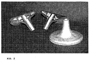
- FIG. 2 shows a manufactured hollow valve member according to the preferred embodiment as a whole component (right) and cut (left).
Landscapes
- Engineering & Computer Science (AREA)
- Mechanical Engineering (AREA)
- Manufacturing & Machinery (AREA)
- Physics & Mathematics (AREA)
- Geometry (AREA)
- General Engineering & Computer Science (AREA)
- Powder Metallurgy (AREA)
- Organic Low-Molecular-Weight Compounds And Preparation Thereof (AREA)
- Turbine Rotor Nozzle Sealing (AREA)
Abstract
Description
Die vorliegende Erfindung betrifft ein Verfahren zur Herstellung von Bauteilen für Verbrennungsmotoren oder Turbinen, insbesondere zur Herstellung von Hohlventilbauteilen.The present invention relates to a method for the production of components for internal combustion engines or turbines, in particular for the production of hollow valve components.
Von Verbrennungsmotoren werden heutzutage hohe Leistungen und ein geringer Kraftstoffverbrauch erwartet. Ventile zum Gasaustausch, wie sie in Verbrennungsmotoren verwendet werden, müssen sehr hohen Betriebstemperaturen und mechanischen Beanspruchungen standhalten. Einlassventile, die bei jedem Ansaugtakt von kühlen Frischgasen umströmt und gekühlt werden, erreichen Ventilteller-Temperaturen von über 500°C. Auslassventile erreichen Temperaturen von über 800°C.Today's combustion engines are expected to deliver high performance and low fuel consumption. Gas exchange valves used in internal combustion engines must withstand very high operating temperatures and mechanical stresses. Inlet valves, which are surrounded and cooled by cool fresh gases at each intake stroke, achieve valve plate temperatures of over 500 ° C. Outlet valves reach temperatures of over 800 ° C.
Da es sich bei Ventilen um bewegliche Bauteile handelt, wächst die aufzubringende Antriebsleistung exponentiell mit dem Gewicht der oszillierenden Massen, d. h. der Ventile. Daraus ergibt sich die Forderung, Ventile bezüglich des Gewichts ohne Einbußen der mechanischen und thermischen Festigkeit weiter zu optimieren.Since valves are moving parts, the drive power to be applied grows exponentially with the weight the oscillating masses, ie the valves. This results in the requirement to further optimize valves in terms of weight without sacrificing mechanical and thermal resistance.
Hohlventile mit einem Schaft, einem Ventilkegel und einem Ventilteller, wobei Ventilkegel und Ventilteller gemeinsam einen Hohlraum bilden, sind beispielsweise aus der
Aufgabe der Erfindung ist es daher ein Verfahren zur Herstellung von Hohlventilbauteilen wie Ventilkegeln oder Ventiltellern bereitzustellen, mit dem wirtschaftlich auch andere Materialien verarbeitet werden können.The object of the invention is therefore to provide a method for producing hollow valve components such as valve cones or valve plates, with which other materials can be processed economically.
Die Aufgabe wird durch ein Verfahren zur Herstellung von Hohlventilbauteilen für Verbrennungsmotoren oder Turbinen gelöst, bei dem
- (a) Metallpulver und/oder Metalllegierungspulver mit einem Bindemittel und gegebenenfalls einem Zuschlagstoff in einem Kneter vermischt werden,
- (b) die Mischung durch Spritzgießen in Form gebracht wird,
- (c) die in Form gebrachte Masse chemisch entbindert wird,
- (d) die chemisch entbinderte Masse bei einer Temperatur von weniger als 450°C thermisch entbindert wird,
- (e) die chemisch und thermisch entbinderte Masse bei einer Temperatur unterhalb der Schmelztemperatur des Metalls und/oder der Metalllegierung zur Herstellung des Bauteils gesintert wird.
- (a) metal powder and / or metal alloy powder are mixed with a binder and optionally an aggregate in a kneader,
- (b) shaping the mixture by injection molding,
- (c) the mass formed is chemically debinded,
- (d) the chemically debonded mass is thermally debindered at a temperature of less than 450 ° C,
- (E) the chemically and thermally debindered mass is sintered at a temperature below the melting temperature of the metal and / or the metal alloy for the production of the component.
Die Erfindung betrifft auch die damit hergestellten Hohlventilbauteile. Mit dem erfindungsgemäßen Verfahren lassen sich neben den martensitisch-ferritischen und austenitischen Stählen oder Nikkelbasislegierungen insbesondere auch Titanbasiswerkstoffe wirtschaftlich zu Hohlventilbauteilen verarbeiten, womit eine weitere Gewichtsersparnis gegenüber bekannten Hohlventilen erreicht werden kann. Bevorzugt werden Titanlegierungen verwendet, die Aluminium und/oder Vanadium als zusätzliche Bestandteile enthalten. Diese zusätzlichen Legierungsbestandteile sind jeweils vorzugsweise in einer Menge von 2 bis 10 Gew.-% auf Basis des Gesamtgewichts der Legierung enthalten.The invention also relates to the hollow valve components produced therewith. In addition to the martensitic-ferritic and austenitic steels or nickel-based alloys, titanium-based materials can also be economically processed to hollow-valve components in particular with the method according to the invention, thus achieving a further weight saving over known hollow valves. Titanium alloys containing aluminum and / or vanadium as additional constituents are preferably used. These additional alloying ingredients are each preferably contained in an amount of 2 to 10% by weight based on the total weight of the alloy.
Das Bindemittel ist vorzugsweise ausgewählt aus der Gruppe bestehend aus: Polyamiden, Polyoxymethylen, Polycarbonat, Styrol-Acrylnitril-Copolymerisat, Polyimid, natürlichen Wachsen und Ölen, Duroplasten, Cyanaten, Polypropylen, Polyacetat, Polyethylen, Ethylen-Vinylacetat, Polyvinylalkohol, Polyvinylchlorid, Polystyrol, Polymethylmethacrylat, Anilinen, Mineralölen, Wasser, Agar, Glycerin, Polyvinylbutyryl, Polybutylmethacrylat, Cellulose, Ölsäure, Phtalaten, Paraffinwachsen, Carnaubawachs, Ammoniumpolyacrylat, Digylceridstearat und -oleat, Glycerylmonostearat, Isopropyltitanat, Lithiumstearat, Monoglyceriden, Formaldehyd, Octylsäurephosphat, Olefinsulfonaten, Phosphatestern, Stearinsäure und Mischungen derselben. Der Volumentanteil des Bindemittels ist vorzugsweise kleiner als 60%, bevorzugter 20 bis 50%.The binder is preferably selected from the group consisting of: polyamides, polyoxymethylene, polycarbonate, styrene-acrylonitrile copolymer, polyimide, natural waxes and oils, thermosets, cyanates, polypropylene, polyacetate, polyethylene, ethylene-vinyl acetate, polyvinyl alcohol, polyvinyl chloride, polystyrene, Polymethyl methacrylate, anilines, mineral oils, water, agar, glycerin, polyvinyl butyryl, polybutyl methacrylate, cellulose, oleic acid, phthalates, paraffin waxes, carnauba wax, ammonium polyacrylate, diglyceride stearate and oleate, glyceryl monostearate, isopropyl titanate, lithium stearate, monoglycerides, formaldehyde, octyl acid phosphate, olefin sulfonates, phosphate esters, stearic acid and mixtures thereof. The volume fraction of the binder is preferably less than 60%, more preferably 20 to 50%.
Die Vermischung im Kneter erfolgt vorzugsweise bei einer Temperatur von 50 bis 250°C, besonders bevorzugt 90 bis 150°C.The mixing in the kneader is preferably carried out at a temperature of 50 to 250 ° C, more preferably 90 to 150 ° C.
Auch das Spritzgießen erfolgt vorzugsweise bei einer Temperatur der Mischung von 90 bis 150°C und bevorzugt bei einem Druck von 400 bis 800 bar.The injection molding is preferably carried out at a temperature of the mixture of 90 to 150 ° C and preferably at a pressure of 400 to 800 bar.
Die chemische Entbinderung erfolgt bevorzugt in einem Paraffinbad, vorzugsweise in einem Hexanbad. Die chemische Entbinderung erfolgt bei einer Temperatur von vorzugsweise 10 bis 65°C, bevorzugter von 30 bis 50°C.The chemical debinding is preferably carried out in a paraffin bath, preferably in a hexane bath. The chemical debinding is carried out at a temperature of preferably 10 to 65 ° C, more preferably from 30 to 50 ° C.
Die thermische Entbinderung erfolgt bei einer Temperatur von weniger als 450°C, bevorzugt 200 bis 350°C und vorzugsweise im Vakuum bei einem Druck von vorzugsweise 2 bis 20 mbar.The thermal debinding is carried out at a temperature of less than 450 ° C, preferably 200 to 350 ° C and preferably in a vacuum at a pressure of preferably 2 to 20 mbar.
Die Sinterung erfolgt vorzugsweise bei 80 bis 90% der Schmelztemperatur des Metalls bzw. der Metalllegierung und bevorzugter in einer Schutzgasatmosphäre. Vorzugsweise ist das Schutzgas Argon. Alternativ kann die Sinterung auch im Vakuum erfolgen. In diesem Fall beträgt der Druck vorzugsweise 10-3 bis 10-5 mbar.The sintering is preferably carried out at 80 to 90% of the melting temperature of the metal or the metal alloy and more preferably in a protective gas atmosphere. Preferably, the protective gas is argon. Alternatively, the sintering can also be done in a vacuum. In this case, the pressure is preferably 10 -3 to 10 -5 mbar.
Derartig hergestellte Holhventilbauteile lassen sich auf konventionelle Weise durch form- und kraftschlüssige sowie schmelzflüssige Fügeverfahren miteinander verbinden. Beispielsweise können Ventilteller und Ventilkegel durch eine Schrumpfverbindung zusammengefügt werden. Ventilkegel und Ventilschaft können durch ein schmelzflüssiges Fügeverfahren verbunden werden.Such Holhventilbauteile produced can be connected to each other in a conventional manner by positive and non-positive and molten joining methods. For example, valve disk and poppet can be joined together by a shrink connection. Valve stem and valve stem can be connected by a molten joining process.
Mit dem oben beschriebenen Verfahren wurde eine Titanlegierung mit 6 Gew.-% Aluminium und 4 Gew.-% Vanadium zu einem Ventilteller und einem Ventilkegel verarbeitet. Ventilkegel und - teller wurden durch eine Schrumpfverbindung zusammengefügt.Using the method described above, a titanium alloy containing 6% by weight of aluminum and 4% by weight of vanadium was processed into a valve disk and a poppet. Valve cones and plates were assembled by means of a shrink connection.
Claims (22)
- Process for the production of a hollow-valve component for combustion engines or turbines, in which(a) metal powder and/or metal alloy powder are mixed in a compounder with a binding agent and optionally an aggregate material,(b) the mixture is shaped by injection moulding,(c) the shaped compound is chemically debound,(d) the chemically debound compound is thermally debound at a temperature of less than 450°C,(e) the chemically and thermally debound compound is sintered at a temperature below the melting temperature of the metal and/or the metal alloy to produce the component.
- Process according to claim 1, wherein the hollow-valve component is a valve cone.
- Process according to claim 1, wherein the hollow-valve component is a valve disk.
- Process according to one of claims 1 to 3, characterized in that a titanium alloy is used as metal-alloy powder.
- Process according to claim 4, characterized in that the titanium alloy contains aluminium and/or vanadium as additional constituents.
- Process according to claim 5, characterized in that the titanium alloy contains 2 to 10 wt.-% aluminium and/or 2 to 10 wt.-% vanadium based on the overall weight of the alloy.
- Process according to one of the previous claims, characterized in that the binding agent is selected from the group consisting of: polyamides, polyoxymethylene, polycarbonate, styrene-acrylonitrile-copolymerisate, polyimide, natural waxes and oils, thermosetting plastics, cyanates, polypropylene, polyacetate, polyethylene, ethylene vinyl acetate, polyvinyl alcohol, polyvinyl chloride, polystyrene, polymethyl methacylate, anilines, mineral oils, water, agar, glycerol, polyvinyl butyryl, polybutyl methacrylate, cellulose, oleic acid, phthalates, paraffin waxes, carnauba wax, ammonium polyacrylate, digylceride stearate and oleate, glyceryl monostearate, isopropyl titanate, lithium stearate, monoglycerides, formaldehyde, octanoic acid phosphate, olefin sulphonates, phosphate esters, stearic acid and mixtures of same.
- Process according to one of the previous claims, characterized in that the proportion by volume of the binder in the mixture is less than 60%.
- Process according to claim 8, characterized in that the proportion by volume of the binding agent in the mixture is 20% to 50%.
- Process according to one of the previous claims, characterized in that the mixing in the compounder is carried out at a temperature in the range from 50 to 250°C.
- Process according to one of the previous claims, characterized in that the injection moulding is carried out at a temperature of the mixture of 90 to 150°C.
- Process according to one of the previous claims, characterized in that the injection moulding is carried out at a temperature of 400 to 800 bar.
- Process according to one of the previous claims, characterized in that the chemical debinding is carried out in a hexane bath.
- Process according to one of the previous claims, characterized in that the chemical debinding is carried out at a temperature of 10 to 65°C.
- Process according to claim 14, characterized in that the chemical debinding is carried out at a temperature of 30 to 50°C.
- Process according to one of the previous claims, characterized in that the thermal debinding is carried out at a pressure of 2 to 20 mbar.
- Process according to one of the previous claims, characterized in that the sintering is carried out at 80% to 90% of the melting temperature of the metal or metal alloy.
- Process according to one of the previous claims, characterized in that the sintering is carried out under an inert gas atmosphere.
- Process according to claim 18, characterized in that the inert gas is argon.
- Process according to one of claims 1 to 17, characterized in that the sintering is carried out under vacuum.
- Hollow-valve component which is produced by a process according to one of claims 1 to 20, characterized in that it is composed of a titanium-based alloy.
- Hollow-valve component according to claim 21, characterized in that in addition to titanium the titanium-based alloy contains 2 to 10 wt.-% aluminium and/or 2 to 10 wt.-% vanadium.
Applications Claiming Priority (1)
| Application Number | Priority Date | Filing Date | Title |
|---|---|---|---|
| DE102006049844A DE102006049844A1 (en) | 2006-10-20 | 2006-10-20 | Process for the production of components for internal combustion engines or turbines |
Publications (2)
| Publication Number | Publication Date |
|---|---|
| EP1925682A1 EP1925682A1 (en) | 2008-05-28 |
| EP1925682B1 true EP1925682B1 (en) | 2010-02-03 |
Family
ID=38657272
Family Applications (1)
| Application Number | Title | Priority Date | Filing Date |
|---|---|---|---|
| EP07118021A Not-in-force EP1925682B1 (en) | 2006-10-20 | 2007-10-08 | Process for the production of an hollow valve component for combustion engines or turbines and the produced hollow valve component |
Country Status (8)
| Country | Link |
|---|---|
| US (1) | US20080092383A1 (en) |
| EP (1) | EP1925682B1 (en) |
| JP (1) | JP2008180211A (en) |
| CN (1) | CN101413410B (en) |
| AT (1) | ATE457039T1 (en) |
| DE (2) | DE102006049844A1 (en) |
| ES (1) | ES2337302T3 (en) |
| PT (1) | PT1925682E (en) |
Families Citing this family (14)
| Publication number | Priority date | Publication date | Assignee | Title |
|---|---|---|---|---|
| ES2738003T3 (en) * | 2004-10-15 | 2020-01-17 | Taisei Kogyo Co Ltd | Production process of porous sinter, porous sinter and porous sinter molding material |
| PT2468436E (en) * | 2010-12-16 | 2013-07-10 | Helmholtz Zentrum Geesthacht | Method for manufacturing metal casings with structured surfaces |
| CA2865325C (en) | 2012-02-24 | 2021-03-02 | Hoeganaes Corporation | Improved lubricant system for use in powder metallurgy |
| CN104117677B (en) * | 2013-04-23 | 2017-02-08 | 昆山广兴电子有限公司 | Manufacturing method of metal fan wheel |
| CN103240418B (en) * | 2013-05-23 | 2014-12-24 | 北京科技大学 | Near-net shaping method for charging turbine with hollow internal structure |
| FR3037514B1 (en) * | 2015-06-16 | 2019-08-09 | Safran Aircraft Engines | METHOD FOR MANUFACTURING A THREE-DIMENSIONAL PIECE FRYED FROM A POWDER AND INSTALLATION FOR CARRYING OUT SAID METHOD |
| CN105624452B (en) * | 2016-01-05 | 2018-04-24 | 南方科技大学 | Method for preparing porous intermetallic compound |
| ITUA20163944A1 (en) | 2016-05-30 | 2017-11-30 | Nuovo Pignone Tecnologie Srl | Process for making a component of a turbomachine, to a component obtainable consequently and turbomachine comprising the same / Process for obtaining a turbomachinery component, a component obtainable from it and a turbomachine which comprises it |
| EP3615254B1 (en) * | 2017-04-27 | 2021-02-17 | Federal-Mogul Valvetrain GmbH | Method of manufacturing a poppet valve |
| EP3524280B1 (en) | 2018-02-12 | 2020-01-08 | Helmholtz-Zentrum Geesthacht Zentrum für Material- und Küstenforschung GmbH | Method for producing a metallic implant |
| CN109108267B (en) * | 2018-08-03 | 2019-12-20 | 深圳市富荣新材料科技有限公司 | Composition, preparation method and application in field of metal injection molding material |
| CN109897980B (en) * | 2019-02-22 | 2020-07-21 | 北京科技大学 | Powder injection molding method of titanium or titanium alloy powder and titanium or titanium alloy product |
| CN113399667B (en) * | 2021-06-11 | 2022-08-16 | 深圳市泛海统联精密制造股份有限公司 | Titanium alloy metal powder injection molding feed and preparation method thereof |
| CN114472879B (en) * | 2021-12-20 | 2023-04-25 | 中南大学 | A kind of binder for pure titanium powder injection molding and its preparation method and application |
Family Cites Families (7)
| Publication number | Priority date | Publication date | Assignee | Title |
|---|---|---|---|---|
| DE3120501C2 (en) * | 1981-05-22 | 1983-02-10 | MTU Motoren- und Turbinen-Union München GmbH, 8000 München | "Process and device for the production of molded parts" |
| JPH02274382A (en) * | 1989-04-12 | 1990-11-08 | Nippon Steel Corp | Hard facing method by welding for engine valve |
| US6351258B1 (en) * | 1997-06-30 | 2002-02-26 | Sony Corporation | Switcher system and I/O switching method |
| DE19804053A1 (en) * | 1998-02-03 | 1999-08-05 | Mwp Mahle J Wizemann Pleuco Gm | Lightweight valve |
| DE10336701B4 (en) * | 2003-08-09 | 2006-12-21 | Mtu Aero Engines Gmbh | Process for the production of components |
| DE102004053874A1 (en) * | 2004-11-04 | 2006-05-11 | Gkss-Forschungszentrum Geesthacht Gmbh | Method for producing products from a metallic composite material |
| EP1926929B1 (en) * | 2005-09-20 | 2009-02-25 | Veritas Ag | Valve device |
-
2006
- 2006-10-20 DE DE102006049844A patent/DE102006049844A1/en not_active Withdrawn
-
2007
- 2007-10-08 AT AT07118021T patent/ATE457039T1/en active
- 2007-10-08 ES ES07118021T patent/ES2337302T3/en active Active
- 2007-10-08 DE DE502007002782T patent/DE502007002782D1/en active Active
- 2007-10-08 PT PT07118021T patent/PT1925682E/en unknown
- 2007-10-08 EP EP07118021A patent/EP1925682B1/en not_active Not-in-force
- 2007-10-09 US US11/869,309 patent/US20080092383A1/en not_active Abandoned
- 2007-10-19 JP JP2007272213A patent/JP2008180211A/en not_active Withdrawn
- 2007-10-19 CN CN2007101633815A patent/CN101413410B/en not_active Expired - Fee Related
Also Published As
| Publication number | Publication date |
|---|---|
| ES2337302T3 (en) | 2010-04-22 |
| DE102006049844A1 (en) | 2008-04-24 |
| EP1925682A1 (en) | 2008-05-28 |
| ATE457039T1 (en) | 2010-02-15 |
| DE502007002782D1 (en) | 2010-03-25 |
| CN101413410B (en) | 2012-06-27 |
| CN101413410A (en) | 2009-04-22 |
| US20080092383A1 (en) | 2008-04-24 |
| JP2008180211A (en) | 2008-08-07 |
| PT1925682E (en) | 2010-05-10 |
Similar Documents
| Publication | Publication Date | Title |
|---|---|---|
| EP1925682B1 (en) | Process for the production of an hollow valve component for combustion engines or turbines and the produced hollow valve component | |
| DE2628582C3 (en) | Composite turbine wheel and process for its manufacture | |
| DE602004011156T2 (en) | Method for connecting a shaft to a titanium aluminide turbine rotor | |
| DE3120501A1 (en) | "METHOD AND DEVICE FOR PRODUCING MOLDED PARTS" | |
| DE68922873T2 (en) | Gas turbine, shroud for a gas turbine and method for manufacturing the shroud. | |
| DE60315550T2 (en) | Abradable metallic or ceramic material; Shaped bodies, housings containing this material and its manufacture | |
| EP2468436B1 (en) | Method for manufacturing metal casings with structured surfaces | |
| DE60304191T2 (en) | Injector for fuel valve in a diesel engine and method of manufacturing an injector | |
| US10995389B2 (en) | Composition for fabricating parts out of titanium aluminide by sintering powder, and a fabrication method using such a composition | |
| EP1268868B1 (en) | Powder metallurgical method for producing high-density shaped parts | |
| EP2001621A2 (en) | Method for production of a honeycomb seal | |
| US20060018780A1 (en) | Method and composition for making a wire | |
| EP3335820A2 (en) | Composite body and method for its production | |
| EP3027341A1 (en) | Insert part that can be infiltrated | |
| DE10331397A1 (en) | Production of blade segments for gas turbines comprises using a powder metallurgical injection molding | |
| DE102004057360A1 (en) | Process to manufacture a seal forming part of a honeycomb structure in a gas turbine aero-engine by screen-print application of mantle to metal base | |
| EP1717539B1 (en) | Method of manufacturing a slide of a firearm | |
| EP1634972A2 (en) | Refractory alloy for metal injection molding | |
| DE19505689C2 (en) | Casting mold for the production of castings from reactive metals | |
| DE10343780A1 (en) | Method for producing components and holding device | |
| EP0568951A2 (en) | High-temperature resistant material | |
| DE102005033625B4 (en) | Method for producing and / or repairing an integrally bladed rotor | |
| DE10336701B4 (en) | Process for the production of components | |
| US20250162029A1 (en) | Alloy powder, method for manufacturing a part based on this alloy, and part thus obtained | |
| EP0437685A1 (en) | Soot filter |
Legal Events
| Date | Code | Title | Description |
|---|---|---|---|
| PUAI | Public reference made under article 153(3) epc to a published international application that has entered the european phase |
Free format text: ORIGINAL CODE: 0009012 |
|
| 17P | Request for examination filed |
Effective date: 20071011 |
|
| AK | Designated contracting states |
Kind code of ref document: A1 Designated state(s): AT BE BG CH CY CZ DE DK EE ES FI FR GB GR HU IE IS IT LI LT LU LV MC MT NL PL PT RO SE SI SK TR |
|
| AX | Request for extension of the european patent |
Extension state: AL BA HR MK RS |
|
| 17Q | First examination report despatched |
Effective date: 20080901 |
|
| AKX | Designation fees paid |
Designated state(s): AT BE BG CH CY CZ DE DK EE ES FI FR GB GR HU IE IS IT LI LT LU LV MC MT NL PL PT RO SE SI SK TR |
|
| GRAP | Despatch of communication of intention to grant a patent |
Free format text: ORIGINAL CODE: EPIDOSNIGR1 |
|
| RTI1 | Title (correction) |
Free format text: PROCESS FOR THE PRODUCTION OF AN HOLLOW VALVE COMPONENT FOR COMBUSTION ENGINES OR TURBINES AND THE PRODUCED HOLLOW VALVE COMPONENT |
|
| GRAS | Grant fee paid |
Free format text: ORIGINAL CODE: EPIDOSNIGR3 |
|
| GRAA | (expected) grant |
Free format text: ORIGINAL CODE: 0009210 |
|
| AK | Designated contracting states |
Kind code of ref document: B1 Designated state(s): AT BE BG CH CY CZ DE DK EE ES FI FR GB GR HU IE IS IT LI LT LU LV MC MT NL PL PT RO SE SI SK TR |
|
| REG | Reference to a national code |
Ref country code: GB Ref legal event code: FG4D Free format text: NOT ENGLISH |
|
| REG | Reference to a national code |
Ref country code: CH Ref legal event code: EP Ref country code: CH Ref legal event code: NV Representative=s name: E. BLUM & CO. AG PATENT- UND MARKENANWAELTE VSP |
|
| REG | Reference to a national code |
Ref country code: IE Ref legal event code: FG4D |
|
| REF | Corresponds to: |
Ref document number: 502007002782 Country of ref document: DE Date of ref document: 20100325 Kind code of ref document: P |
|
| REG | Reference to a national code |
Ref country code: ES Ref legal event code: FG2A Ref document number: 2337302 Country of ref document: ES Kind code of ref document: T3 |
|
| REG | Reference to a national code |
Ref country code: NL Ref legal event code: T3 |
|
| REG | Reference to a national code |
Ref country code: PT Ref legal event code: SC4A Free format text: AVAILABILITY OF NATIONAL TRANSLATION Effective date: 20100503 |
|
| LTIE | Lt: invalidation of european patent or patent extension |
Effective date: 20100203 |
|
| PG25 | Lapsed in a contracting state [announced via postgrant information from national office to epo] |
Ref country code: IS Free format text: LAPSE BECAUSE OF FAILURE TO SUBMIT A TRANSLATION OF THE DESCRIPTION OR TO PAY THE FEE WITHIN THE PRESCRIBED TIME-LIMIT Effective date: 20100603 Ref country code: LT Free format text: LAPSE BECAUSE OF FAILURE TO SUBMIT A TRANSLATION OF THE DESCRIPTION OR TO PAY THE FEE WITHIN THE PRESCRIBED TIME-LIMIT Effective date: 20100203 |
|
| PG25 | Lapsed in a contracting state [announced via postgrant information from national office to epo] |
Ref country code: PL Free format text: LAPSE BECAUSE OF FAILURE TO SUBMIT A TRANSLATION OF THE DESCRIPTION OR TO PAY THE FEE WITHIN THE PRESCRIBED TIME-LIMIT Effective date: 20100203 Ref country code: SI Free format text: LAPSE BECAUSE OF FAILURE TO SUBMIT A TRANSLATION OF THE DESCRIPTION OR TO PAY THE FEE WITHIN THE PRESCRIBED TIME-LIMIT Effective date: 20100203 Ref country code: FI Free format text: LAPSE BECAUSE OF FAILURE TO SUBMIT A TRANSLATION OF THE DESCRIPTION OR TO PAY THE FEE WITHIN THE PRESCRIBED TIME-LIMIT Effective date: 20100203 Ref country code: LV Free format text: LAPSE BECAUSE OF FAILURE TO SUBMIT A TRANSLATION OF THE DESCRIPTION OR TO PAY THE FEE WITHIN THE PRESCRIBED TIME-LIMIT Effective date: 20100203 |
|
| REG | Reference to a national code |
Ref country code: IE Ref legal event code: FD4D |
|
| PG25 | Lapsed in a contracting state [announced via postgrant information from national office to epo] |
Ref country code: CY Free format text: LAPSE BECAUSE OF FAILURE TO SUBMIT A TRANSLATION OF THE DESCRIPTION OR TO PAY THE FEE WITHIN THE PRESCRIBED TIME-LIMIT Effective date: 20100203 Ref country code: GR Free format text: LAPSE BECAUSE OF FAILURE TO SUBMIT A TRANSLATION OF THE DESCRIPTION OR TO PAY THE FEE WITHIN THE PRESCRIBED TIME-LIMIT Effective date: 20100504 Ref country code: EE Free format text: LAPSE BECAUSE OF FAILURE TO SUBMIT A TRANSLATION OF THE DESCRIPTION OR TO PAY THE FEE WITHIN THE PRESCRIBED TIME-LIMIT Effective date: 20100203 Ref country code: SE Free format text: LAPSE BECAUSE OF FAILURE TO SUBMIT A TRANSLATION OF THE DESCRIPTION OR TO PAY THE FEE WITHIN THE PRESCRIBED TIME-LIMIT Effective date: 20100203 Ref country code: RO Free format text: LAPSE BECAUSE OF FAILURE TO SUBMIT A TRANSLATION OF THE DESCRIPTION OR TO PAY THE FEE WITHIN THE PRESCRIBED TIME-LIMIT Effective date: 20100203 Ref country code: IE Free format text: LAPSE BECAUSE OF FAILURE TO SUBMIT A TRANSLATION OF THE DESCRIPTION OR TO PAY THE FEE WITHIN THE PRESCRIBED TIME-LIMIT Effective date: 20100203 |
|
| PG25 | Lapsed in a contracting state [announced via postgrant information from national office to epo] |
Ref country code: SK Free format text: LAPSE BECAUSE OF FAILURE TO SUBMIT A TRANSLATION OF THE DESCRIPTION OR TO PAY THE FEE WITHIN THE PRESCRIBED TIME-LIMIT Effective date: 20100203 Ref country code: CZ Free format text: LAPSE BECAUSE OF FAILURE TO SUBMIT A TRANSLATION OF THE DESCRIPTION OR TO PAY THE FEE WITHIN THE PRESCRIBED TIME-LIMIT Effective date: 20100203 Ref country code: BG Free format text: LAPSE BECAUSE OF FAILURE TO SUBMIT A TRANSLATION OF THE DESCRIPTION OR TO PAY THE FEE WITHIN THE PRESCRIBED TIME-LIMIT Effective date: 20100503 |
|
| PLBE | No opposition filed within time limit |
Free format text: ORIGINAL CODE: 0009261 |
|
| STAA | Information on the status of an ep patent application or granted ep patent |
Free format text: STATUS: NO OPPOSITION FILED WITHIN TIME LIMIT |
|
| 26N | No opposition filed |
Effective date: 20101104 |
|
| PG25 | Lapsed in a contracting state [announced via postgrant information from national office to epo] |
Ref country code: DK Free format text: LAPSE BECAUSE OF FAILURE TO SUBMIT A TRANSLATION OF THE DESCRIPTION OR TO PAY THE FEE WITHIN THE PRESCRIBED TIME-LIMIT Effective date: 20100203 |
|
| PGFP | Annual fee paid to national office [announced via postgrant information from national office to epo] |
Ref country code: DE Payment date: 20101006 Year of fee payment: 4 |
|
| BERE | Be: lapsed |
Owner name: GKSS-FORSCHUNGSZENTRUM GEESTHACHT G.M.B.H. Effective date: 20101031 |
|
| PG25 | Lapsed in a contracting state [announced via postgrant information from national office to epo] |
Ref country code: MC Free format text: LAPSE BECAUSE OF NON-PAYMENT OF DUE FEES Effective date: 20101031 |
|
| REG | Reference to a national code |
Ref country code: DE Ref legal event code: R081 Ref document number: 502007002782 Country of ref document: DE Owner name: HELMHOLTZ-ZENTRUM GEESTHACHT ZENTRUM FUER MATE, DE Free format text: FORMER OWNER: GKSS-FORSCHUNGSZENTRUM GEESTHACHT GMBH, 21502 GEESTHACHT, DE Effective date: 20110418 |
|
| PG25 | Lapsed in a contracting state [announced via postgrant information from national office to epo] |
Ref country code: BE Free format text: LAPSE BECAUSE OF NON-PAYMENT OF DUE FEES Effective date: 20101031 |
|
| PG25 | Lapsed in a contracting state [announced via postgrant information from national office to epo] |
Ref country code: IT Free format text: LAPSE BECAUSE OF NON-PAYMENT OF DUE FEES Effective date: 20101008 Ref country code: MT Free format text: LAPSE BECAUSE OF FAILURE TO SUBMIT A TRANSLATION OF THE DESCRIPTION OR TO PAY THE FEE WITHIN THE PRESCRIBED TIME-LIMIT Effective date: 20100203 |
|
| PGFP | Annual fee paid to national office [announced via postgrant information from national office to epo] |
Ref country code: IT Payment date: 20101031 Year of fee payment: 4 |
|
| PGFP | Annual fee paid to national office [announced via postgrant information from national office to epo] |
Ref country code: ES Payment date: 20111115 Year of fee payment: 5 Ref country code: FR Payment date: 20111103 Year of fee payment: 5 Ref country code: CH Payment date: 20111012 Year of fee payment: 5 Ref country code: PT Payment date: 20110930 Year of fee payment: 5 Ref country code: NL Payment date: 20111021 Year of fee payment: 5 |
|
| GBPC | Gb: european patent ceased through non-payment of renewal fee |
Effective date: 20111008 |
|
| PG25 | Lapsed in a contracting state [announced via postgrant information from national office to epo] |
Ref country code: GB Free format text: LAPSE BECAUSE OF NON-PAYMENT OF DUE FEES Effective date: 20111008 |
|
| PG25 | Lapsed in a contracting state [announced via postgrant information from national office to epo] |
Ref country code: HU Free format text: LAPSE BECAUSE OF FAILURE TO SUBMIT A TRANSLATION OF THE DESCRIPTION OR TO PAY THE FEE WITHIN THE PRESCRIBED TIME-LIMIT Effective date: 20100804 Ref country code: LU Free format text: LAPSE BECAUSE OF NON-PAYMENT OF DUE FEES Effective date: 20101008 |
|
| PG25 | Lapsed in a contracting state [announced via postgrant information from national office to epo] |
Ref country code: TR Free format text: LAPSE BECAUSE OF FAILURE TO SUBMIT A TRANSLATION OF THE DESCRIPTION OR TO PAY THE FEE WITHIN THE PRESCRIBED TIME-LIMIT Effective date: 20100203 |
|
| REG | Reference to a national code |
Ref country code: PT Ref legal event code: MM4A Free format text: LAPSE DUE TO NON-PAYMENT OF FEES Effective date: 20130408 |
|
| REG | Reference to a national code |
Ref country code: NL Ref legal event code: V1 Effective date: 20130501 |
|
| REG | Reference to a national code |
Ref country code: CH Ref legal event code: PL |
|
| REG | Reference to a national code |
Ref country code: FR Ref legal event code: ST Effective date: 20130628 |
|
| PG25 | Lapsed in a contracting state [announced via postgrant information from national office to epo] |
Ref country code: LI Free format text: LAPSE BECAUSE OF NON-PAYMENT OF DUE FEES Effective date: 20121031 Ref country code: DE Free format text: LAPSE BECAUSE OF NON-PAYMENT OF DUE FEES Effective date: 20130501 Ref country code: CH Free format text: LAPSE BECAUSE OF NON-PAYMENT OF DUE FEES Effective date: 20121031 |
|
| REG | Reference to a national code |
Ref country code: DE Ref legal event code: R119 Ref document number: 502007002782 Country of ref document: DE Effective date: 20130501 |
|
| PG25 | Lapsed in a contracting state [announced via postgrant information from national office to epo] |
Ref country code: FR Free format text: LAPSE BECAUSE OF NON-PAYMENT OF DUE FEES Effective date: 20121031 Ref country code: IT Free format text: LAPSE BECAUSE OF NON-PAYMENT OF DUE FEES Effective date: 20121008 Ref country code: PT Free format text: LAPSE BECAUSE OF NON-PAYMENT OF DUE FEES Effective date: 20130408 Ref country code: NL Free format text: LAPSE BECAUSE OF NON-PAYMENT OF DUE FEES Effective date: 20130501 |
|
| REG | Reference to a national code |
Ref country code: AT Ref legal event code: MM01 Ref document number: 457039 Country of ref document: AT Kind code of ref document: T Effective date: 20121031 |
|
| REG | Reference to a national code |
Ref country code: ES Ref legal event code: FD2A Effective date: 20140115 |
|
| PG25 | Lapsed in a contracting state [announced via postgrant information from national office to epo] |
Ref country code: AT Free format text: LAPSE BECAUSE OF NON-PAYMENT OF DUE FEES Effective date: 20121031 |
|
| PG25 | Lapsed in a contracting state [announced via postgrant information from national office to epo] |
Ref country code: ES Free format text: LAPSE BECAUSE OF NON-PAYMENT OF DUE FEES Effective date: 20121009 |