EP1925576B1 - Reinforced belt for powerturn applications - Google Patents
Reinforced belt for powerturn applications Download PDFInfo
- Publication number
- EP1925576B1 EP1925576B1 EP20070022633 EP07022633A EP1925576B1 EP 1925576 B1 EP1925576 B1 EP 1925576B1 EP 20070022633 EP20070022633 EP 20070022633 EP 07022633 A EP07022633 A EP 07022633A EP 1925576 B1 EP1925576 B1 EP 1925576B1
- Authority
- EP
- European Patent Office
- Prior art keywords
- weft
- cords
- belting
- fabric ply
- layer
- Prior art date
- Legal status (The legal status is an assumption and is not a legal conclusion. Google has not performed a legal analysis and makes no representation as to the accuracy of the status listed.)
- Ceased
Links
Images
Classifications
-
- B—PERFORMING OPERATIONS; TRANSPORTING
- B65—CONVEYING; PACKING; STORING; HANDLING THIN OR FILAMENTARY MATERIAL
- B65G—TRANSPORT OR STORAGE DEVICES, e.g. CONVEYORS FOR LOADING OR TIPPING, SHOP CONVEYOR SYSTEMS OR PNEUMATIC TUBE CONVEYORS
- B65G15/00—Conveyors having endless load-conveying surfaces, i.e. belts and like continuous members, to which tractive effort is transmitted by means other than endless driving elements of similar configuration
- B65G15/30—Belts or like endless load-carriers
- B65G15/32—Belts or like endless load-carriers made of rubber or plastics
- B65G15/34—Belts or like endless load-carriers made of rubber or plastics with reinforcing layers, e.g. of fabric
-
- B—PERFORMING OPERATIONS; TRANSPORTING
- B65—CONVEYING; PACKING; STORING; HANDLING THIN OR FILAMENTARY MATERIAL
- B65G—TRANSPORT OR STORAGE DEVICES, e.g. CONVEYORS FOR LOADING OR TIPPING, SHOP CONVEYOR SYSTEMS OR PNEUMATIC TUBE CONVEYORS
- B65G15/00—Conveyors having endless load-conveying surfaces, i.e. belts and like continuous members, to which tractive effort is transmitted by means other than endless driving elements of similar configuration
- B65G15/02—Conveyors having endless load-conveying surfaces, i.e. belts and like continuous members, to which tractive effort is transmitted by means other than endless driving elements of similar configuration for conveying in a circular arc
-
- Y—GENERAL TAGGING OF NEW TECHNOLOGICAL DEVELOPMENTS; GENERAL TAGGING OF CROSS-SECTIONAL TECHNOLOGIES SPANNING OVER SEVERAL SECTIONS OF THE IPC; TECHNICAL SUBJECTS COVERED BY FORMER USPC CROSS-REFERENCE ART COLLECTIONS [XRACs] AND DIGESTS
- Y10—TECHNICAL SUBJECTS COVERED BY FORMER USPC
- Y10T—TECHNICAL SUBJECTS COVERED BY FORMER US CLASSIFICATION
- Y10T442/00—Fabric [woven, knitted, or nonwoven textile or cloth, etc.]
- Y10T442/30—Woven fabric [i.e., woven strand or strip material]
- Y10T442/3179—Woven fabric is characterized by a particular or differential weave other than fabric in which the strand denier or warp/weft pick count is specified
-
- Y—GENERAL TAGGING OF NEW TECHNOLOGICAL DEVELOPMENTS; GENERAL TAGGING OF CROSS-SECTIONAL TECHNOLOGIES SPANNING OVER SEVERAL SECTIONS OF THE IPC; TECHNICAL SUBJECTS COVERED BY FORMER USPC CROSS-REFERENCE ART COLLECTIONS [XRACs] AND DIGESTS
- Y10—TECHNICAL SUBJECTS COVERED BY FORMER USPC
- Y10T—TECHNICAL SUBJECTS COVERED BY FORMER US CLASSIFICATION
- Y10T442/00—Fabric [woven, knitted, or nonwoven textile or cloth, etc.]
- Y10T442/30—Woven fabric [i.e., woven strand or strip material]
- Y10T442/3472—Woven fabric including an additional woven fabric layer
Definitions
- the present invention is directed to a powerturn conveyor belting. More specifically, the reinforced belting has an internal constriction designed to improve performance of the belting in the powerturn application.
- Powerturn belts are a type of specialized conveyor belts wherein the conveyor belt does not travel in a straight path parallel to its longitudinal length. At a minimum, powerturn belts travel through a 30° arc. At the extreme end, a powerturn belt will travel multiple 360° turns in what is referred to as a spiral conveyor. Such belts have applications in a variety of industries, varying from warehouses, airports, and the food industry.
- At least one longitudinal edge of the belt is provided with means that are mechanically gripped by the conveyor system.
- Such means includes guide means as shown in US 3951256 and resin moldings, such as disclosed in US 6834760 .
- the present invention is directed to a powerturn conveyor belting having a multi-layered construction, according to claim 1, wherein, the belt has an improved performance.
- the powerturn conveyor belting has a finite length, closed loop structure.
- the belting has at least two plies of fabric and a tracking mechanism that is adapted for connecting the belting to a powerturn system.
- One of the plies is an interwoven ply comprised of two layers of weft cords and a plurality of warp cords interweaving through the two layers of weft cords, each warp cord having the following repeating weave pattern of passing over at least two but not more than five weft cords in the first weft layer, passing between the two weft layers for a distance of at least two weft cords as measured by passing under at least two weft cords (WE) in the first weft layer and by passing over at least two weft cords (WE) in the second weft layer before passing through the second weft layer, and then passing under at least two but not more than five weft cords in the second weft layer.
- WE weft cords
- WE weft cords
- the second ply of fabric has a weave pattern selected from the group consisting of plain weave, satin weave, or twill weave.
- each warp cord in the first ply passes over at least three but more than four weft cords in the first weft layer and passes under at least three but more than four weft cords in the second weft layer.
- the cords of the first fabric ply are selected from the group consisting of polyester, polyamide, cotton, nylon, fiberglass, carbon fiber, polybenzoxazole (PBO) fibers or any blends or mixes thereof.
- the first fabric ply is the outermost ply of the closed loop structure, creating a more durable belting surface for use in heavy duty powerturn applications.
- the second ply of fabric has a weave pattern comprising a single layer of weft cords.
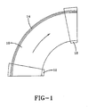
- FIG. 1 illustrates a powerturn conveyor belt system having a direction of travel indicated by the arrow D.
- the system has the basic elements of a finite length, closed loop belt 10 that travels about a pair of conical pulleys 12.
- a tracking mechanism 14 that connects the belt 10 to the powerturn system.
- the specifics of the tracking system 14 are not critical to the present invention, and any known or conventional tracking system may be employed.
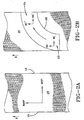
- the finite length, powerturn, closed loop belt 10 is manufactured first as a continuous length belting 16, having a length in direction D, opposed lateral edges 18, and reinforcing cords, see FIG. 2A .
- Reinforcing cords within the continuous length belt are defined as warp cords when the cords are parallel to the length direction D of the continuous belt and as weft cords when transverse, or perpendicular, to the length direction E.
- the continuous length belt is cut into finite length belting arcs 20, see FIG. 2B , and spliced to form the closed loop belt 10. Due to the arc cuts in the continuous length belting 16, along a first portion 22 of the finite length belting arc 20, the reinforcing warp cords WA and weft cords WE of the belting arc correspond to the warp and weft cords as the continuous length belt 16.
- the cords that were the warp cords WA in the first portion 22 begin to function as weft cords WE' and the cords that were the weft cords WE in the first portion begin to function as warp cords WA'.
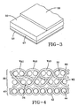
- the continuous length belting 16 which is cut and spliced to form the finite length, closed loop belt 10, is a two-ply structure having first and second reinforcing plies embedded in a matrix and bonded together, see FIG. 3 .
- the top ply 30 is a composite ply formed of two layers 32, 34 of weft cords WE, and repeating sequence of three warp cords WA1, WA2, WA3, interwoven among the two layers 32, 34 of weft cords WE, see FIG. 4 .
- Each warp cord WA1, WA2, WA3 passes over at least two weft cords WE in the top weft layer 32, between the two weft cord layers 32, 34 for a length approximately equal to at least two, preferably three, but not more than five, weft cords WE, and then under at least two weft cords WE in the bottom weft layer 34 before traveling back up to the top weft layer 32 to repeat the weaving pattern.
- the illustrated warp cords WA1, WA2, WA3 pass over and under two weft cords WE in each layer 32, 34.
- the maximum number of weft cords WE in each layer being passed over and under by the warp cords WA1, WA2, WA3 is five weft cords WE, preferably three to four weft cords WE.
- the three warp cords WA1, WA2, WA3 arc adjacent to each other in the completed fabric, creating a tight fabric pattern.
- the warp and weft cords WA1, WA2, WA3, WE of the top ply are preferably formed of the same material; however, to vary the strengths of the fabric in the different directions, the warp and weft yarns may be formed of different materials.
- the cords may be selected from the group of polyester, polyamide, cotton, nylon, fiberglass, carbon fiber, polybenzoxazole (PBO) fibers or any blends or mixes thereof.
- the bottom ply 40 is a simpler fabric ply than the top ply 30 and has only a single layer of weft cords 44.
- the fabric ply 40 is a simple warp and weft woven ply, with each warp cord 42 passing over and under the weft cords 44 in a pattern commonly referred to as a plain weave.
- the bottom ply 40 may alternatively be woven in a conventional satin or twill weave.
- the cords 42, 44 of the bottom ply 40 are selected from the group of polyester, polyamide, cotton, nylon, fiberglass, carbon fiber, polybenzoxazole (PBO) fibers or any blends or mixes thereof.
- the top ply 30 provides the majority of the strength to the belting 16 and closed loop belt and provides the belting 16 and the closed loop belt 10 with improved durability.
- Each fabric ply 30, 40 is embedded in an elastomeric or thermoplastic material, such as rubber or a polyvinyl chloride (pvc) compound or other types of resins used for conveyor belt applications.
- the embedding resin is selected based upon the intended end use of the belting.
- the two ply structure may be provided with a top and bottom cover layer 50, 52, that may or may not be provided with a imprint to create a three dimensional, or roughened, surface.
- the cover layer is not reinforced with any type of continuous cords or yarns.
- the bottom cover layer may or may not be reinforced by textile means.
- the belting may be used in other conveyor belt applications wherein a closed loop system is created by fastening ends of the belting together.
Landscapes
- Engineering & Computer Science (AREA)
- Mechanical Engineering (AREA)
- Belt Conveyors (AREA)
- Woven Fabrics (AREA)
Description
- The present invention is directed to a powerturn conveyor belting. More specifically, the reinforced belting has an internal constriction designed to improve performance of the belting in the powerturn application.
- Powerturn belts are a type of specialized conveyor belts wherein the conveyor belt does not travel in a straight path parallel to its longitudinal length. At a minimum, powerturn belts travel through a 30° arc. At the extreme end, a powerturn belt will travel multiple 360° turns in what is referred to as a spiral conveyor. Such belts have applications in a variety of industries, varying from warehouses, airports, and the food industry.
- To assist the belt in turning, at least one longitudinal edge of the belt is provided with means that are mechanically gripped by the conveyor system. Such means includes guide means as shown in
US 3951256 and resin moldings, such as disclosed inUS 6834760 . - Conventional conveyor belts for powerturn applications are formed of several thin plies of a simple warp/weft woven fabric, wherein both plies have the same reinforcement structure. The reinforcement structure is embedded in either an elastomeric or plastic matrix such as PVC, depending on the powerturn system requirements. While such belts have proven satisfactory in the past, such belts fail to consider the different tensions placed on the belt due to the curves and u-turns the belt travels in the powerturn system. This can lead to an reduction in durability and performance of the conveyor belt.
- From
EP 1 609 899 A2 a woven reinforced fabric for conveyor belts is known. From US 3, 100,565 an endless belt for a conveyor-belt turn is known andUS 5,667,058 describes a powered conveyor belt turn. - The present invention is directed to a powerturn conveyor belting having a multi-layered construction, according to claim 1, wherein, the belt has an improved performance.
- The powerturn conveyor belting has a finite length, closed loop structure. The belting has at least two plies of fabric and a tracking mechanism that is adapted for connecting the belting to a powerturn system. One of the plies is an interwoven ply comprised of two layers of weft cords and a plurality of warp cords interweaving through the two layers of weft cords, each warp cord having the following repeating weave pattern of passing over at least two but not more than five weft cords in the first weft layer, passing between the two weft layers for a distance of at least two weft cords as measured by passing under at least two weft cords (WE) in the first weft layer and by passing over at least two weft cords (WE) in the second weft layer before passing through the second weft layer, and then passing under at least two but not more than five weft cords in the second weft layer. The second ply of fabric has a weave pattern selected from the group consisting of plain weave, satin weave, or twill weave. Preferably, each warp cord in the first ply passes over at least three but more than four weft cords in the first weft layer and passes under at least three but more than four weft cords in the second weft layer.
- In another aspect of the powerturn belting, the cords of the first fabric ply are selected from the group consisting of polyester, polyamide, cotton, nylon, fiberglass, carbon fiber, polybenzoxazole (PBO) fibers or any blends or mixes thereof.
- In another aspect of the invention, the first fabric ply is the outermost ply of the closed loop structure, creating a more durable belting surface for use in heavy duty powerturn applications.
- In another aspect of the invention the second ply of fabric has a weave pattern comprising a single layer of weft cords.
- The invention will be described by way of example and with reference to the accompanying drawings in which:
-
FIG. 1 illustrates a 90° powerturn application; -
FIG. 2A is an overview of a continuous length belting; -
FIG. 2B is an overview of a continuous length belting showing the cutting lines for a belting section to be used in manufacturing a powerturn belting; -
FIG. 3 is a fabric cross-sectional view in accordance with the present invention; and -
FIG. 4 is a more detailed view of the fabric plies used in the belting. - The following language is of the best presently contemplated mode or modes of carrying out the invention. This description is made for the purpose of illustrating the general principles of the invention and should not be taken in a limiting sense. The scope of the invention is best determined by reference to the appended claims. The reference numerals as depicted in the drawings are the same as those referred to in the specification. For purposes of this application, the various embodiments illustrated in the figures each use the same reference numeral for similar components. The structures employ basically the same components with variations in location or quantity thereby giving rise to the alternative constructions in which the inventive concept can be practiced.
-
FIG. 1 illustrates a powerturn conveyor belt system having a direction of travel indicated by the arrow D. The system has the basic elements of a finite length, closedloop belt 10 that travels about a pair ofconical pulleys 12. Along the longest edge of thebelt 10 is atracking mechanism 14 that connects thebelt 10 to the powerturn system. The specifics of thetracking system 14 are not critical to the present invention, and any known or conventional tracking system may be employed. - The finite length, powerturn, closed
loop belt 10 is manufactured first as a continuous length belting 16, having a length in direction D, opposedlateral edges 18, and reinforcing cords, seeFIG. 2A . Reinforcing cords within the continuous length belt are defined as warp cords when the cords are parallel to the length direction D of the continuous belt and as weft cords when transverse, or perpendicular, to the length direction E. - To form the finite length, closed loop belt for the powerturn application, the continuous length belt is cut into finite length
belting arcs 20, seeFIG. 2B , and spliced to form the closedloop belt 10. Due to the arc cuts in the continuous length belting 16, along afirst portion 22 of the finite lengthbelting arc 20, the reinforcing warp cords WA and weft cords WE of the belting arc correspond to the warp and weft cords as thecontinuous length belt 16. However, in thesecond portion 24 of the finite lengthbelting arc 20, due to the arc shape and the direction of travel T of the finite length, closedloop belt 10, past the mid-point of the finite lengthbelting arc 20, the cords that were the warp cords WA in thefirst portion 22 begin to function as weft cords WE' and the cords that were the weft cords WE in the first portion begin to function as warp cords WA'. - In the belt of the present invention, the continuous length belting 16, which is cut and spliced to form the finite length, closed
loop belt 10, is a two-ply structure having first and second reinforcing plies embedded in a matrix and bonded together, seeFIG. 3 . Thetop ply 30 is a composite ply formed of twolayers layers FIG. 4 . Each warp cord WA1, WA2, WA3 passes over at least two weft cords WE in thetop weft layer 32, between the twoweft cord layers bottom weft layer 34 before traveling back up to thetop weft layer 32 to repeat the weaving pattern. The illustrated warp cords WA1, WA2, WA3 pass over and under two weft cords WE in eachlayer top ply 30 may be compromised for situations where the belt is subjected to high stresses and loads. - In the
top ply 30, the three warp cords WA1, WA2, WA3 arc adjacent to each other in the completed fabric, creating a tight fabric pattern. The warp and weft cords WA1, WA2, WA3, WE of the top ply are preferably formed of the same material; however, to vary the strengths of the fabric in the different directions, the warp and weft yarns may be formed of different materials. The cords may be selected from the group of polyester, polyamide, cotton, nylon, fiberglass, carbon fiber, polybenzoxazole (PBO) fibers or any blends or mixes thereof. - The
bottom ply 40 is a simpler fabric ply than thetop ply 30 and has only a single layer ofweft cords 44. Thefabric ply 40 is a simple warp and weft woven ply, with eachwarp cord 42 passing over and under theweft cords 44 in a pattern commonly referred to as a plain weave. Thebottom ply 40 may alternatively be woven in a conventional satin or twill weave. Thecords - In the belting 16 and the
closed loop belt 10, due to the different types of fabric plies 30, 40, the top ply 30 provides the majority of the strength to the belting 16 and closed loop belt and provides the belting 16 and theclosed loop belt 10 with improved durability. - Each fabric ply 30, 40 is embedded in an elastomeric or thermoplastic material, such as rubber or a polyvinyl chloride (pvc) compound or other types of resins used for conveyor belt applications. The embedding resin is selected based upon the intended end use of the belting. The two ply structure may be provided with a top and
bottom cover layer top cover layer 50 is provided, the cover layer is not reinforced with any type of continuous cords or yarns. The bottom cover layer may or may not be reinforced by textile means. - While the use of the continuous length belting is disclosed as being particularly useful for powerturn applications, the belting may be used in other conveyor belt applications wherein a closed loop system is created by fastening ends of the belting together.
Claims (8)
- A powerturn conveyor belting having a finite length, closed loop structure, the belting being formed of a first fabric ply (30), a second fabric ply (40), and a tracking mechanism (14) that is adapted for connecting the belting to a powerturn system, characterized in, that the first fabric ply (30) is an interwoven ply comprised of two layers of weft cords(WE) and a plurality of warp cords (WA1, WA2, ...) interweaving through the two layers of weft cords (WE), each warp cord (WA1, WA2, ...) having the following repeating weave pattern of passing over at least two but not more than five cords in the first weft layer, passing between the two weft layers for a distance of at least two weft cords as measured by passing under at least two weft cords (WE) in the first weft layer and by passing over at least two weft cords (WE) in the second weft layer before passing through the second weft layer, and then passing under at least two but not more than five weft cords (WE) in the second weft layer, and wherein the second fabric ply has a weave pattern selected from the group consisting of plain weave, satin weave, or twill weave.
- The belting of claim 1 wherein the cords of the first fabric ply (30) are selected from the group consisting of polyester, polyamide, cotton, fiberglass, carbon fiber, polybenzoxazole (PBO) fibers or any blends of mixes thereof.
- The belting of claim one of the foregoing claims wherein each fabric ply (30, 40) is embedded in an elastomeric or thermoplastic resin.
- The belting of one of the foregoing claims further comprising a top cover (50).
- The belting of one of the foregoing claims wherein each warp cord (WA) in the first fabric ply (30) passes over at least three but more than four weft cords (WE) in the first weft layer and passes under at least three but not more than four weft cords in the second weft layer.
- The belting of one of the foregoing claims wherein the second fabric ply (40) has a weave pattern comprising a single layer of weft cords.
- The belting of one of the foregoing claims wherein the belting has a pair of opposing ends and the ends are fastened together to create a closed loop belt.
- The belting of one to the foregoing claims wherein the belt has an outer side and an internal side, and the first fabric ply is closer to the outer side than the second fabric ply.
Applications Claiming Priority (1)
| Application Number | Priority Date | Filing Date | Title |
|---|---|---|---|
| US11/603,739 US8192317B2 (en) | 2006-11-22 | 2006-11-22 | Reinforced belt for powerturn applications |
Publications (3)
| Publication Number | Publication Date |
|---|---|
| EP1925576A2 EP1925576A2 (en) | 2008-05-28 |
| EP1925576A3 EP1925576A3 (en) | 2009-12-30 |
| EP1925576B1 true EP1925576B1 (en) | 2013-02-13 |
Family
ID=38988078
Family Applications (1)
| Application Number | Title | Priority Date | Filing Date |
|---|---|---|---|
| EP20070022633 Ceased EP1925576B1 (en) | 2006-11-22 | 2007-11-22 | Reinforced belt for powerturn applications |
Country Status (7)
| Country | Link |
|---|---|
| US (1) | US8192317B2 (en) |
| EP (1) | EP1925576B1 (en) |
| JP (1) | JP2008162803A (en) |
| CN (1) | CN101240476B (en) |
| CA (1) | CA2611800C (en) |
| MX (1) | MX2007014639A (en) |
| ZA (1) | ZA200710115B (en) |
Families Citing this family (10)
| Publication number | Priority date | Publication date | Assignee | Title |
|---|---|---|---|---|
| EP2452901B1 (en) * | 2009-07-07 | 2019-03-27 | Mitsubishi Heavy Industries Machinery Systems, Ltd. | Heat-resistant laminated conveyor belt |
| CN102899774B (en) * | 2010-04-13 | 2013-12-11 | 北京光华纺织集团有限公司 | Flexibility-controllable fabric |
| ES2460090T3 (en) | 2010-06-04 | 2014-05-13 | Knauf Gips Kg | Conveyor belt and procedure to make a plasterboard |
| CN103534181B (en) * | 2011-03-05 | 2015-09-09 | 三和技术株式会社 | The high-speed conveyor be made up of fabric and device thereof |
| EP2792904B1 (en) * | 2011-12-14 | 2016-08-10 | Bando Chemical Industries, Ltd. | Friction transmission belt and method for producing same |
| CH706587A1 (en) * | 2012-06-04 | 2013-12-13 | Graf & Co Ag | Clothing support. |
| WO2014049816A1 (en) * | 2012-09-28 | 2014-04-03 | 三和テクノ株式会社 | Conveyor belt and drive belt comprising knitted belt, and conveyor device using conveyor belt |
| CN104828464B (en) * | 2015-04-13 | 2017-01-18 | 佛山市南海区嘉润良工业皮带有限公司 | Pressureproof industrial belt |
| US9969137B2 (en) | 2016-04-29 | 2018-05-15 | Contitech Transportbandsysteme Gmbh | Multi ply thermoplastic conveyor belt |
| IT202100029396A1 (en) * | 2021-11-19 | 2023-05-19 | Alfabelts Srl | TRANSPORT BELT AND PROCEDURE FOR MAKING IT |
Family Cites Families (29)
| Publication number | Priority date | Publication date | Assignee | Title |
|---|---|---|---|---|
| US1227427A (en) * | 1917-02-08 | 1917-05-22 | Charles Schwartz | Method of making tire-casings. |
| US1923275A (en) * | 1931-06-10 | 1933-08-22 | Du Pont | Candy support |
| US2088447A (en) * | 1936-03-23 | 1937-07-27 | Encor Corp | Woven wire belt for paper making machines |
| US3100565A (en) | 1959-10-05 | 1963-08-13 | Charles L Fry | Endless belt for a conveyor-belt turn |
| US3296062A (en) * | 1965-06-24 | 1967-01-03 | Us Rubber Co | Belt fabric |
| US3327839A (en) * | 1965-07-08 | 1967-06-27 | Ajem Lab Inc | Conveyor apparatus |
| US3664907A (en) * | 1970-02-02 | 1972-05-23 | Huyck Corp | Industrial conveyor belts |
| US3951256A (en) * | 1971-03-10 | 1976-04-20 | Gurewitz Samuel J | Power belt turn conveyor |
| US4071050A (en) * | 1972-09-01 | 1978-01-31 | Nordiska Maskinfilt Aktiebolaget | Double-layer forming fabric |
| JPS5887392A (en) * | 1981-10-08 | 1983-05-25 | 日本フエルト株式会社 | Papermaking felt and production thereof |
| US4503113A (en) * | 1982-03-12 | 1985-03-05 | Huyck Corporation | Papermaker felt with a three-layered base fabric |
| FR2568275B1 (en) * | 1984-07-27 | 1986-09-05 | Chomarat & Cie | TEXTILE REINFORCEMENT BASED ON GLASS YARNS USEFUL FOR THE PRODUCTION OF LAMINATED COMPLEXES |
| JPH0720083Y2 (en) * | 1986-10-06 | 1995-05-10 | 三ツ星ベルト株式会社 | Conveyor belts that can move along curved paths |
| US5104726A (en) * | 1989-12-29 | 1992-04-14 | Woven Electronics Corporation | Woven fabric and process for reinforced structural composites |
| JPH03259810A (en) * | 1990-03-09 | 1991-11-19 | Bridgestone Corp | Belt easy to laterally move carried material |
| EP0533356A1 (en) * | 1991-08-28 | 1993-03-24 | Scapa Group Plc | Filter belt |
| JPH058821A (en) * | 1991-09-21 | 1993-01-19 | Bridgestone Corp | Conveyor belt with less friction and meandering |
| US5169709A (en) * | 1991-10-16 | 1992-12-08 | Wangner Systems Corporation | Paper machine forming fabric with controlled porosity |
| US5164249A (en) * | 1991-11-22 | 1992-11-17 | Wangner Systems Corporation | Controlled porosity papermaking fabric |
| US5376440A (en) * | 1993-03-31 | 1994-12-27 | Ikeda Bussan Co., Ltd. | Woven fabric for seat belt |
| JP2673338B2 (en) * | 1993-06-18 | 1997-11-05 | 三ツ星ベルト株式会社 | Wide belt for corrugated board production |
| JP2972978B2 (en) * | 1994-08-29 | 1999-11-08 | 三ツ星ベルト株式会社 | Canvas core for wide belt and method of manufacturing same |
| US5667058A (en) | 1995-04-27 | 1997-09-16 | United Parcel Service Of America, Inc. | Powered conveyor belt turn |
| AT403486B (en) * | 1995-12-19 | 1998-02-25 | Hutter & Schrantz Papiermaschi | Engineering fabric for use in papermaking machines |
| JP3595701B2 (en) * | 1998-09-30 | 2004-12-02 | 三ツ星ベルト株式会社 | Conveying belt and method of manufacturing the same |
| US6349749B1 (en) * | 1999-07-09 | 2002-02-26 | Geschmay Corp. | Woven fabric |
| JP2002019938A (en) | 2000-07-07 | 2002-01-23 | Habajitto Nippon Kk | Deformed conveyance belt |
| US6491598B1 (en) * | 2000-10-09 | 2002-12-10 | The Goodyear Tire & Rubber Company | Power transmission belt |
| US7304006B2 (en) * | 2004-06-24 | 2007-12-04 | The Goodyear Tire & Rubber Company | High tear interwoven belt fabric |
-
2006
- 2006-11-22 US US11/603,739 patent/US8192317B2/en active Active
-
2007
- 2007-11-21 JP JP2007302262A patent/JP2008162803A/en active Pending
- 2007-11-21 CA CA2611800A patent/CA2611800C/en active Active
- 2007-11-22 EP EP20070022633 patent/EP1925576B1/en not_active Ceased
- 2007-11-22 CN CN2007103051908A patent/CN101240476B/en not_active Expired - Fee Related
- 2007-11-22 MX MX2007014639A patent/MX2007014639A/en not_active Application Discontinuation
- 2007-11-22 ZA ZA200710115A patent/ZA200710115B/en unknown
Also Published As
| Publication number | Publication date |
|---|---|
| CN101240476A (en) | 2008-08-13 |
| CA2611800A1 (en) | 2008-05-22 |
| EP1925576A3 (en) | 2009-12-30 |
| MX2007014639A (en) | 2008-10-28 |
| US8192317B2 (en) | 2012-06-05 |
| CN101240476B (en) | 2012-06-27 |
| ZA200710115B (en) | 2010-08-25 |
| JP2008162803A (en) | 2008-07-17 |
| EP1925576A2 (en) | 2008-05-28 |
| CA2611800C (en) | 2016-01-05 |
| US20080119101A1 (en) | 2008-05-22 |
Similar Documents
| Publication | Publication Date | Title |
|---|---|---|
| CA2611800C (en) | Reinforced belt for powerturn applications | |
| US4407333A (en) | Belting fabric | |
| CA2693442C (en) | Dual crimped warp fabric for conveyor belt applications | |
| US7815043B2 (en) | Laterally flexible reinforced structure | |
| JPH03503397A (en) | conveyor belt | |
| CN121803601A (en) | Belt type friction power transmission belt | |
| EP0014561A1 (en) | Power transmission belt of the raw-edge type | |
| CN1312415C (en) | Endless power transmission belt | |
| CA2413755C (en) | Reinforcing band for conveyer belts, and conveyer belt using the same | |
| EP3680374B1 (en) | A belt comprising a fabric with bilateral satin weave | |
| JP2000001206A (en) | Conveyor belt | |
| EP1175358A1 (en) | Conveyor belting with reinforcing fabric formed from three interlaced layers | |
| US20120125473A1 (en) | Dual layer twill fabric for conveyor belt applications | |
| JPH0643186Y2 (en) | Straight conveyor belt | |
| JP3004708U (en) | Joint structure of toothed belt for transportation | |
| JPWO2003016181A1 (en) | Cloth reinforced conveyor belt | |
| GB2245525A (en) | Sheet reinforcing material | |
| KR102487838B1 (en) | Belts containing fabrics for application of fabric and shear stress | |
| WO2024203055A1 (en) | Conveying belt and belt canvas | |
| JPH02114074A (en) | Caterpillar belt | |
| JP2006273487A (en) | Conveyor belt | |
| CA2513519A1 (en) | Interwoven belt fabric | |
| HK1081505A (en) | Fabric-reinforced belt for conveying food |
Legal Events
| Date | Code | Title | Description |
|---|---|---|---|
| PUAI | Public reference made under article 153(3) epc to a published international application that has entered the european phase |
Free format text: ORIGINAL CODE: 0009012 |
|
| AK | Designated contracting states |
Kind code of ref document: A2 Designated state(s): AT BE BG CH CY CZ DE DK EE ES FI FR GB GR HU IE IS IT LI LT LU LV MC MT NL PL PT RO SE SI SK TR |
|
| AX | Request for extension of the european patent |
Extension state: AL BA HR MK RS |
|
| PUAL | Search report despatched |
Free format text: ORIGINAL CODE: 0009013 |
|
| AK | Designated contracting states |
Kind code of ref document: A3 Designated state(s): AT BE BG CH CY CZ DE DK EE ES FI FR GB GR HU IE IS IT LI LT LU LV MC MT NL PL PT RO SE SI SK TR |
|
| AX | Request for extension of the european patent |
Extension state: AL BA HR MK RS |
|
| 17P | Request for examination filed |
Effective date: 20100202 |
|
| 17Q | First examination report despatched |
Effective date: 20100305 |
|
| AKX | Designation fees paid |
Designated state(s): DE NL |
|
| RIC1 | Information provided on ipc code assigned before grant |
Ipc: B65G 15/02 20060101ALN20120726BHEP Ipc: B65G 15/34 20060101AFI20120726BHEP |
|
| GRAP | Despatch of communication of intention to grant a patent |
Free format text: ORIGINAL CODE: EPIDOSNIGR1 |
|
| GRAS | Grant fee paid |
Free format text: ORIGINAL CODE: EPIDOSNIGR3 |
|
| GRAA | (expected) grant |
Free format text: ORIGINAL CODE: 0009210 |
|
| AK | Designated contracting states |
Kind code of ref document: B1 Designated state(s): DE NL |
|
| RIN2 | Information on inventor provided after grant (corrected) |
Inventor name: LEE, KYUNG EUN Inventor name: HAINES, EDWIN LEE Inventor name: DEANS, DOUGLAS BROOKE Inventor name: RADDING, PETER EARL Inventor name: YU, JENNY ZHAOXIA |
|
| REG | Reference to a national code |
Ref country code: DE Ref legal event code: R096 Ref document number: 602007028369 Country of ref document: DE Effective date: 20130411 |
|
| REG | Reference to a national code |
Ref country code: NL Ref legal event code: T3 |
|
| PLBE | No opposition filed within time limit |
Free format text: ORIGINAL CODE: 0009261 |
|
| STAA | Information on the status of an ep patent application or granted ep patent |
Free format text: STATUS: NO OPPOSITION FILED WITHIN TIME LIMIT |
|
| 26N | No opposition filed |
Effective date: 20131114 |
|
| REG | Reference to a national code |
Ref country code: DE Ref legal event code: R097 Ref document number: 602007028369 Country of ref document: DE Effective date: 20131114 |
|
| REG | Reference to a national code |
Ref country code: NL Ref legal event code: HC Owner name: CONTITECH USA, INC.; US Free format text: DETAILS ASSIGNMENT: CHANGE OF OWNER(S), CHANGE OF OWNER(S) NAME; FORMER OWNER NAME: VEYANCE TECHNOLOGIES, INC. Effective date: 20170926 |
|
| REG | Reference to a national code |
Ref country code: DE Ref legal event code: R082 Ref document number: 602007028369 Country of ref document: DE Representative=s name: DREISS PATENTANWAELTE PARTG MBB, DE Ref country code: DE Ref legal event code: R081 Ref document number: 602007028369 Country of ref document: DE Owner name: CONTITECH USA, INC. (N.D.GES.D. STAATES DELAWA, US Free format text: FORMER OWNER: VEYANCE TECHNOLOGIES, INC., FAIRLAWN, OHIO, US |
|
| REG | Reference to a national code |
Ref country code: DE Ref legal event code: R084 Ref document number: 602007028369 Country of ref document: DE |
|
| P01 | Opt-out of the competence of the unified patent court (upc) registered |
Effective date: 20230602 |
|
| PGFP | Annual fee paid to national office [announced via postgrant information from national office to epo] |
Ref country code: NL Payment date: 20231120 Year of fee payment: 17 |
|
| PGFP | Annual fee paid to national office [announced via postgrant information from national office to epo] |
Ref country code: DE Payment date: 20231130 Year of fee payment: 17 |
|
| REG | Reference to a national code |
Ref country code: DE Ref legal event code: R119 Ref document number: 602007028369 Country of ref document: DE |
|
| REG | Reference to a national code |
Ref country code: NL Ref legal event code: MM Effective date: 20241201 |
|
| PG25 | Lapsed in a contracting state [announced via postgrant information from national office to epo] |
Ref country code: NL Free format text: LAPSE BECAUSE OF NON-PAYMENT OF DUE FEES Effective date: 20241201 |
|
| PG25 | Lapsed in a contracting state [announced via postgrant information from national office to epo] |
Ref country code: DE Free format text: LAPSE BECAUSE OF NON-PAYMENT OF DUE FEES Effective date: 20250603 |