EP1925335A1 - Catheter type iontophoresis apparatus - Google Patents
Catheter type iontophoresis apparatus Download PDFInfo
- Publication number
- EP1925335A1 EP1925335A1 EP06797957A EP06797957A EP1925335A1 EP 1925335 A1 EP1925335 A1 EP 1925335A1 EP 06797957 A EP06797957 A EP 06797957A EP 06797957 A EP06797957 A EP 06797957A EP 1925335 A1 EP1925335 A1 EP 1925335A1
- Authority
- EP
- European Patent Office
- Prior art keywords
- side electrode
- electrode assembly
- working
- working side
- ion exchange
- Prior art date
- Legal status (The legal status is an assumption and is not a legal conclusion. Google has not performed a legal analysis and makes no representation as to the accuracy of the status listed.)
- Withdrawn
Links
Images


Classifications
-
- A—HUMAN NECESSITIES
- A61—MEDICAL OR VETERINARY SCIENCE; HYGIENE
- A61M—DEVICES FOR INTRODUCING MEDIA INTO, OR ONTO, THE BODY; DEVICES FOR TRANSDUCING BODY MEDIA OR FOR TAKING MEDIA FROM THE BODY; DEVICES FOR PRODUCING OR ENDING SLEEP OR STUPOR
- A61M25/00—Catheters; Hollow probes
-
- A—HUMAN NECESSITIES
- A61—MEDICAL OR VETERINARY SCIENCE; HYGIENE
- A61N—ELECTROTHERAPY; MAGNETOTHERAPY; RADIATION THERAPY; ULTRASOUND THERAPY
- A61N1/00—Electrotherapy; Circuits therefor
- A61N1/18—Applying electric currents by contact electrodes
- A61N1/20—Applying electric currents by contact electrodes continuous direct currents
- A61N1/30—Apparatus for iontophoresis, i.e. transfer of media in ionic state by an electromotoric force into the body, or cataphoresis
- A61N1/303—Constructional details
- A61N1/306—Arrangements where at least part of the apparatus is introduced into the body
-
- A—HUMAN NECESSITIES
- A61—MEDICAL OR VETERINARY SCIENCE; HYGIENE
- A61N—ELECTROTHERAPY; MAGNETOTHERAPY; RADIATION THERAPY; ULTRASOUND THERAPY
- A61N1/00—Electrotherapy; Circuits therefor
- A61N1/18—Applying electric currents by contact electrodes
- A61N1/20—Applying electric currents by contact electrodes continuous direct currents
- A61N1/30—Apparatus for iontophoresis, i.e. transfer of media in ionic state by an electromotoric force into the body, or cataphoresis
Definitions
- the present invention relates to an iontophoresis device for administering a drug ion to an organism.
- Such iontophoresis device as described above is intended for causing a drug solution to permeate into a skin or a mucosa, and its object has been conventionally a skin or mucosa having a relatively large area of at least about 20 mm in diameter.
- the direct injection of a drug into: a region as an object of endoscopic surgery; part of a region such as a mucosa in a nasal cavity, a mucosa in an oral cavity, an esophageal, a stomach, a small intestine, a large intestine, or an anal; an affected area upon laparoscopic operation in a lung cancer therapy; or part of an organism exposed in laparotomy or the like (pinpoint) may increase a therapeutic effect.
- An object to be achieved by the present invention is to provide an iontophoresis device suitably used upon permeation of a drug solution into part of an organism such as a cancer site in case of a therapy or treatment by means of an endoscope or a laparoscope.
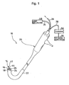
- a catheter-type iontophoresis device 10 includes: a working side electrode assembly 12 and a non-working side electrode assembly 14 each used for administering an ionic drug; a rod-like member 16 for integrally supporting them; and a DC electric power source 30 connected to the working side electrode assembly 12 and the non-working side electrode assembly 14 with different polarities.
- Each of the working side electrode assembly 12 and the non-working side electrode assembly 14 is attached to the tip of the rod-like member 16.
- the rod-like member 16 is detachably supported by the tip of a flexible cable 18.
- the working side electrode assembly 12 and the non-working side electrode assembly 14 are exchangeable integrally with the rod-like member 16.
- the flexible cable 18 is supported by a flexible tube 22 of an endoscopic device 20 so that the cable can freely curve.
- the rod-like member 16 is detachably attached to a tip projecting from the flexible tube 22.
- the endoscopic device 20 has an endoscopic optical system including an optical fiber 24 for irradiation light and an optical fiber 26 for reflected light each passing through the flexible tube 22.
- the optical fiber 24 for irradiation light emits irradiation light from its tip, and the optical fiber 26 for reflected light captures reflected light generated by the irradiation light emitted from the optical fiber 24 for irradiation light at, for example, an affected area in an organism and guides the reflected light to the outside.
- White light is adapted to be incident from a laser light source 58 to be described later on the optical fiber 24 for irradiation light.
- the working electrode assembly 12 and the non-working electrode assembly 14 are connected to different polarities of the DC electric power source 30 via an electric power source circuit (not shown).
- the tip of the rod-like member 16 on the side of the flexible cable 18 is provided with a working side electrode terminal 32 to be connected to the working side electrode assembly 12 and a non-working side electrode terminal 34 to be connected to the non-working side electrode assembly 14.
- the working side electrode terminal 32 and the non-working side electrode terminal 34 are adapted to be connected to an electric power source side working electrode terminal 33 and an electric power source side non-working electrode terminal 35 on the side of the flexible cable 18, respectively, when the rod-like member 16 is attached to the flexible cable 18.
- the electric power source side working electrode terminal 33 and the electric power source side non-working electrode terminal 35 are connected to the DC electric power source 30 arranged further outside the endoscopic device 20 via the electric power source circuit 28.
- the rod-like member 16 is a cylindrical member having the same diameter as that of the flexible cable 18.
- the member 16 is adapted to be attached by threading a male screw portion 16A into a female screw portion 18A at the tip of the flexible cable 18 and to be detached by rotating the male screwportion 16A in a direction opposite to that at the time of threading.
- Fig. 2 is an enlarged view showing a state where the working side electrode assembly 12 and the non-working side electrode assembly 14 are arranged so that their central axis lines are parallel to each other.
- the working side electrode assembly 12 is constituted by laminating a working side electrode 36, an electrolyte solution holding portion 38, a second ion exchange membrane 40, a drug solution holding portion 42, and a first ion exchange membrane 44 in the stated order from the side of the rod-like member 16, and is formed into a disk shape of about 2 to 6 mm in diameter.
- the working side electrode 36 is desirably constituted by a conductive paint applied to the one surface of the base sheet 13 and blended with a nonmetal conductive filler such as a carbon paste.
- the working side electrode 36 can be constituted by a copper plate or a metal thin film, but a metal eluted from the plate or the thin film may transfer to an organism upon administration of a drug. Therefore, the working electrode 36 is preferably nonmetallic.
- the electrolyte solution holding portion 38 is constituted by, for example, an electrolytic paint applied to the working side electrode 36.
- the electrolytic paint is a paint containing an electrolyte, and an electrolyte that is oxidized or reduced more easily than the electrolytic reaction of water (oxidation on a plus pole and reduction on a minus pole) is particularly preferably used.
- electrolyte include: medical agents such as ascorbic acid (vitamin C) and sodium ascorbate; and organic acids such as lactic acid, oxalic acid, malic acid, succinic acid, and fumaric acid and/or salts thereof.
- the use of such electrolyte can suppress the generation of an oxygen gas or a hydrogen gas.
- blending a plurality of kinds of electrolytes serving as a combination of buffer electrolyte solutions when dissolved in a solvent can suppress a change in pH during energization.
- the electrolytic paint is blended with a hydrophilic polymer such as polyvinyl alcohol, polyacrylic acid, polyacrylamide, or polyethylene glycol in order to improve the application property and film-forming property of the paint, and is blended with an appropriate amount of solvent such as water, ethanol, or propanol for adjusting the viscosity of the electrolytic paint.
- a hydrophilic polymer such as polyvinyl alcohol, polyacrylic acid, polyacrylamide, or polyethylene glycol
- solvent such as water, ethanol, or propanol
- the paint may be blended with an appropriate additional component such as a thickener, a thixotropic agent, a defoaming agent, a pigment, a flavor, or a coloring agent.
- the second ion exchange membrane 40 is formed by applying a second ion exchange paint to the electrolyte solution holding portion 38.
- the second ion exchange paint is a paint containing an ion exchange resin into which an ion exchange group using, as a counter ion, an ion having a conductivity type opposite to that of a drug ion in the drug solution holding portion 42 to be described later is introduced.
- the paint is blended with an anion exchange resin.
- the paint is blended with a cation exchange resin.
- the drug solution holding portion 42 is composed of a drug paint applied to the second ion exchange membrane 40.
- the paint is a paint containing a drug (including a precursor for the drug) whose drug component dissociates to plus or minus ions (drug ions) as a result of, for example, dissolution into a solvent such as water.
- a drug whose drug component dissociates to plus ions can include lidocaine hydrochloride as an anesthetic drug and morphine hydrochloride as an anesthetic drug.
- a drug whose drug component dissociates to minus ions can include ascorbic acid as a vitamin agent.
- the first ion exchange membrane 44 is formed of a first ion exchange paint applied to the drug solution holding portion 42.
- the first ion exchange paint is a paint containing an ion exchange resin into which an ion exchange group using, as a counter ion, an ion having the same conductivity type as that of the drug ion in the drug solution holding portion 42 is introduced.
- the paint is blended with an anion/cation exchange resin.
- a cation exchange group an exchange group using a cation as a counter ion
- An ion exchange resin obtained by introducing an anion exchange group such as a primary amino group, a secondary amino group, a tertiary amino group, a quaternary ammonium group, a pyridyl group, an imidazole group, a quaternary pyridinium group, or a quaternary imidazolium group into a polymer having a three-dimensional network structure similar to that in the case of the cation exchange resin can be used as the anion exchange resin without any limitation.
- an anion exchange group an exchange group using an anion as a counter ion
- the non-working side electrode assembly 14 is constituted by laminating a non-working electrode 4 6, a second electrolyte solution holding portion 48, a third ion exchange membrane 50, a third electrolyte solution holding portion 52, and a fourth ion exchange membrane 54 in the stated order on one side of a non-working side base sheet 15, and is formed into a disk shape as in the case of the working side electrode assembly 12.
- the non-working side electrode 46 has the same constitution as that of the working side electrode 36 in the working side electrode assembly 12, and the constitutions and components of the second electrolyte solution holding portion 48 and the third electrolyte solution holding portion 52 are the same as those of the electrolyte solution holding portion 38.
- the third ion exchange membrane 50 is formed of an ion exchange paint applied to the second electrolyte solution holding portion 48.
- the ion exchange paint is the same as the first ion exchange paint of which the first ion exchange membrane 44 is formed, and functions as an ion exchange membrane similar to the first ion exchange membrane 44.
- the fourth ion exchange membrane 54 is formed of the same second ion exchange paint as that described above applied to the third electrolyte solution holding portion 52.
- the fourth ion exchange membrane 54 functions as an ion exchange membrane similar to the second ion exchange membrane 40.
- a working side electrode terminal plate 32A is arranged on the other surface of the base sheet 13, and conduction is established between the working side electrode terminal plate 32A and the working side electrode 36 of the working side electrode assembly 12 through a through-hole formed on the base sheet 13, and the working side electrode terminal plate 32A is connected to the working side electrode terminal 32 through the through-hole.
- a non-working side electrode terminal plate 34A is arranged on the other surface of the non-working side base sheet 15, and conduction is established between the non-working side electrode terminal plate 34A and the non-working side electrode 46 of the non-working side electrode assembly 14 through a through-hole formed on the non-working base sheet 15, and the non-working side electrode terminal plate 34A is connected to the non-working side electrode terminal 34 through the through-hole.
- the first ion exchange membrane 44 and the fourth ion exchange membrane 54 at the tips of the working side electrode assembly 12 and the non-working side electrode assembly 14 are exposed so as tobe capable of contacting with the side of anorganism, respectively.
- the DC electric power source 30 is composed of, for example, an AC/DC converter, and the electric power source circuit 28 between the DC electric power source 30 and the electric power source side working electrode terminal 33 and between the DC electric power source 30 and the electric power source side non-working electrode terminal 35 is provided with a controller 56 for adjusting, out of a current value during energization and an energization time as administration time, at least the current value. As a result, each of the current value and the administration time can be adjusted in a certain range.
- a predetermined amount of spacing S is provided between the first ion exchange membrane 44 and the fourth ion exchange membrane 54 at each of the tips of the working side electrode assembly 12 and the non-working side electrode assembly 14 in order to prevent a current from directly flowing between the membranes upon energization.
- the spacing S has substantially the same size as that of the diameter of each of the first ion exchange membrane 44 and the fourth ion exchange membrane 54.
- White light is applied from the optical fiber 24 for irradiation light.
- Reflected light (image) is guided to the outside by means of the optical fiber for reflected light 26.
- An affected area is identified while the reflected light (image) is observed.
- the working side electrode assembly 12 is pressed against the affected area. No lighting is performed during iontophoresis.
- the working side electrode assembly 12 and the non-working side electrode assembly 14 are attached such that central axes thereof are in parallel with each other.
- the present invention is not limited thereto.
- the working side electrode assembly 12 and the non-working side electrode assembly 14 may be placed such that central axes thereof intersect each other in a tip direction with an angle of 60° between the axes.
- the working side electrode assembly 12 and the non-working side electrode assembly 14 may be placed such that central axes thereof spread out to a tip direction.
- the working side electrode assembly 12 and the non-working side electrode assembly 14 are arranged at the tip of the flexible cable 18 in the endoscopic device 20 with a gap S between the assemblies. Therefore, for example, when a drug solution is caused to permeate into a cancer site of a digestive organ, a doctor grips the endoscopic device 20 to bring the first ion exchange membrane 44 at the tip of the working side electrode assembly 12 at the tip of the flexible cable 18 into close contact with the cancer site and, at the same time, to bring the fourth ion exchange membrane 54 at the tip of the non-working side electrode assembly 14 into close contact with a mucosa or the like near the cancer site for energization.
- a target drug solution can be easily caused to permeate into a target site on a pinpoint basis.
- the working side electrode assembly 12 and the non-working side electrode assembly 14 can be detached together with the rod-like member 16 from the flexible cable 18, so a drug solution can be easily exchanged.
- the catheter-type iontophoresis device 10 can be used for the therapy of the inside of a body by means of a PDT as an anti-cancer remedy involving: applying a photosensitizing reaction substance to, for example, a cancer cell; and irradiating the substance with light to cause the substance to absorb the light.
- the device 10 can be used upon therapy of a superficial esophageal cancer, a superficial gastric cancer, or a cerivical cancer.
- the device 10 can be used for the therapy of the inside of a body, for example, the therapy of gastric ulcer or colitis by means of a method except a PDT.
- the drug solution holding portion 42 in the working side electrode assembly 12 holds a photosensitizing reaction substance, and light having a wavelength to be absorbed by the photosensitizing reaction substance such as ultraviolet light is supplied from the laser light source 58 while being controlled with the controller 56 to the optical fiber 24 for irradiation light so that an affected area can be irradiated with the light.
- a photosensitizing reaction substance such as ultraviolet light
- Light having a wavelength to which a photosensitizing reaction substance is sensitive is used for a PDT.
- a light source emitting light having the wavelength is separately arranged, and white light and light having the wavelength are selectively switched by using means for switching input to the optical fiber for irradiation light 24 (not shown).
- a filter passing only light having the wavelength out of white light may be used without the use of a new light source.
- each of the working electrode assembly and the non-working electrode assembly in the catheter-type iontophoresis device is arranged at the tip of the flexible cable in the endoscopic device.
- An anti-cancer agent is caused to permeate into a pinpoint such as a cancer site in, for example, a digestive organ so that an efficient therapy can be performed with little side effect.
- each of the working electrode assembly and the non-working electrode assembly is exchanged and then an anti-cancer agent is administered. As a result, a therapy and the prevention of recurrence can be simultaneously performed.
Abstract
Description
- The present invention relates to an iontophoresis device for administering a drug ion to an organism.
- Such iontophoresis device as described above is intended for causing a drug solution to permeate into a skin or a mucosa, and its object has been conventionally a skin or mucosa having a relatively large area of at least about 20 mm in diameter.
- On the other hand, the direct injection of a drug into: a region as an object of endoscopic surgery; part of a region such as a mucosa in a nasal cavity, a mucosa in an oral cavity, an esophageal, a stomach, a small intestine, a large intestine, or an anal; an affected area upon laparoscopic operation in a lung cancer therapy; or part of an organism exposed in laparotomy or the like (pinpoint) may increase a therapeutic effect.
- In such case, the permeation of a drug by means of iontophoresis rather than injection is non-invasive and preferable.
- In addition, upon photodynamic therapy (PDT), after a photosensitizing reaction substance has been administered, light is applied so that an anti-cancer action can be expected. However, a patient must not be irradiated with sunlight because the photosensitizing reaction substance circulates through his or her body. In addition, the substance may circulate through any portion other than an affected area to provide a side effect. Therefore, in a PDT, the administration of a photosensitizing reaction substance to only an affected area has been desired.
- An object to be achieved by the present invention is to provide an iontophoresis device suitably used upon permeation of a drug solution into part of an organism such as a cancer site in case of a therapy or treatment by means of an endoscope or a laparoscope.
- The above-described objectives are achieved by the following embodiments of the present invention.
-
- (1) A catheter-type iontophoresis device including a working side electrode assembly and a non-working side electrode assembly each used for administering an ionic drug by iontophoresis and a DC electric power source to be connected to the working side electrode assembly and the non-working side electrode assembly with opposite polarities, characterized by including: a rod-like member for supporting the working side electrode assembly and the non-working side electrode assembly; and an endoscope device for detachably supporting the rod-like member, the working side electrode assembly and the non-working side electrode assembly being disposed at a tip of the rod-like member, a predetermined amount of spacing being provided between the working side electrode assembly and the non-working side electrode assembly, and the rod-like member being detachably supported at a tip of a flexible cable flexibly supported by a flexible tube of the endoscope device.
-
- (2) The catheter-type iontophoresis device according to item (1), characterized in that the ionic drug is a photosensitized reactive material to be activated by absorbing light, and the endoscope device has an irradiation optical system for applying light from a neighborhood of a tip of the working side electrode assembly via the flexible tube.
-
- (3) The catheter-type iontophoresis device according to item (2), characterized in that the endoscope device has an endoscope optical system including an optical fiber for irradiated light for irradiating an inside of an organism with light and an optical fiber for reflected light for introducing reflected irradiated light to an outside, and the irradiation optical system is the optical fiber for irradiated light.
-
- (4) The catheter-type iontophoresis device according to any one of items (1) to (3), characterized in that the flexible cable includes an electric power source side working electrode terminal and an electric power source side non-working electrode terminal connected via wiring from the DC electric power source to the DC electric power source with opposite polarities, the wiring being housed in the flexible cable, the rod-like member has on a proximal end of a side thereof detachable from the flexible cable a working electrode side contact and a non-working electrode side contact which are connected to or are separated from the electric power source side working electrode terminal and the electric power source side non-working electrode terminal when attached to or detached from the flexible cable, and the working electrode side contact and the non-working electrode side contact are connected to a working side electrode and a non-working side electrode in the working side electrode assembly and the non-working side electrode assembly, respectively.
-
- (5) The catheter-type iontophoresis device according to item (4), characterized in that the endoscope device includes a controller for adjusting at least a current value out of a current value during energization and energization time as administration time, the controller being disposed in an electric power source circuit between each of the electric power source side working electrode terminal and the electric power source side non-working electrode terminal and the DC electric power source.
-
- (6) The catheter-type iontophoresis device according to any one of items (1) to (5), characterized in that the working side electrode assembly and the non-working side electrode assembly are disposed such that central axes thereof are in parallel to each other.
-
- (7) The catheter-type iontophoresis device according to any one of items (1) to (5), characterized in that the working side electrode assembly and the non-working side electrode assembly are disposed such that central axes thereof spread in a tip direction.
-
- (8) The catheter-type iontophoresis device according to any one of items (1) to (5), characterized in that the working side electrode assembly and the non-working side electrode assembly are disposed such that central axes thereof intersect each other in a tip direction.
-
- (9) The catheter-type iontophoresis device according to any one of items (1) to (8), characterized in that the working side electrode assembly includes: the working side electrode connected to the DC electric power source having the same polarity as that of a charged ion of the ionic drug; an electrolyte solution holding portion holding an electrolyte solution, the electrolyte solution holding portion being disposed on a front surface of the working electrode; a second ion exchange membrane selecting an ion having a polarity opposite to that of the charged ion of the ionic drug, the second ion exchange membrane being disposed on a front surface of the electrolyte solution holding portion; a drug solution holding portion holding the ionic drug, the drug solution holding portion being disposed on a front surface of the second ion exchange membrane; and a first ion exchange membrane which is the ion exchange membrane selecting an ion having the same polarity as that of the charged ion of the ionic drug, the first ion exchange membrane being disposed on a front surface of the drug solution holding portion, and the non-working side electrode assembly includes: the non-working side electrode connected to the DC electric power source with a polarity opposite to that of the charged ion of the ionic drug; a second electrolyte solution holding portion holding a second electrolyte solution, the second electrolyte solution holding portion being disposed on a front surface of the non-working side electrode; a third ion exchange membrane selecting an ion having a polarity same to that of the charged ion of the ionic drug, the third ion exchange membrane being disposed on a front surface of the second electrolyte solution holding portion; a third electrolyte solution holding portion holding a third electrolyte solution, the third electrolyte solution holding portion being disposed on a front surface of the third ion exchange membrane; and a fourth ion exchange membrane which is the ion exchange membrane selecting an ion having a polarity opposite to that of the charged ion of the ionic drug, the fourth ion exchange membrane being disposed on a front surface of the third electrolyte solution holding portion.
-
- [
Fig. 1 ] A plan view showing an iontophoresis device according to an embodiment of the present invention. - [
Fig. 2 ] An enlarged sectional view showing a main portion of each of a working side electrode assembly and a non-working side electrode assembly. - [
Fig. 3 ] Aplan view showing another example of the arrangement of the working side electrode assembly and the non-working side electrode assembly. - [
Fig. 4 ] A plan view showing still another example of the arrangement of the working side electrode assembly and the non-working side electrode assembly. - Hereinafter, the best mode for carrying out the present invention will be described in detail with reference to the drawings.
- As shown in each of
Figs. 1 and2 , a catheter-type iontophoresis device 10 according to the best mode includes: a workingside electrode assembly 12 and a non-workingside electrode assembly 14 each used for administering an ionic drug; a rod-like member 16 for integrally supporting them; and a DCelectric power source 30 connected to the workingside electrode assembly 12 and the non-workingside electrode assembly 14 with different polarities. - Each of the working
side electrode assembly 12 and the non-workingside electrode assembly 14 is attached to the tip of the rod-like member 16. The rod-like member 16 is detachably supported by the tip of aflexible cable 18. As a result, the workingside electrode assembly 12 and the non-workingside electrode assembly 14 are exchangeable integrally with the rod-like member 16. - The
flexible cable 18 is supported by aflexible tube 22 of anendoscopic device 20 so that the cable can freely curve. The rod-like member 16 is detachably attached to a tip projecting from theflexible tube 22. - The
endoscopic device 20 has an endoscopic optical system including anoptical fiber 24 for irradiation light and anoptical fiber 26 for reflected light each passing through theflexible tube 22. Theoptical fiber 24 for irradiation light emits irradiation light from its tip, and theoptical fiber 26 for reflected light captures reflected light generated by the irradiation light emitted from theoptical fiber 24 for irradiation light at, for example, an affected area in an organism and guides the reflected light to the outside. White light is adapted to be incident from alaser light source 58 to be described later on theoptical fiber 24 for irradiation light. - The working
electrode assembly 12 and thenon-working electrode assembly 14 are connected to different polarities of the DCelectric power source 30 via an electric power source circuit (not shown). - The tip of the rod-
like member 16 on the side of theflexible cable 18 is provided with a workingside electrode terminal 32 to be connected to the workingside electrode assembly 12 and a non-workingside electrode terminal 34 to be connected to the non-workingside electrode assembly 14. - The working
side electrode terminal 32 and the non-workingside electrode terminal 34 are adapted to be connected to an electric power source side workingelectrode terminal 33 and an electric power source sidenon-working electrode terminal 35 on the side of theflexible cable 18, respectively, when the rod-like member 16 is attached to theflexible cable 18. - The electric power source side working
electrode terminal 33 and the electric power source sidenon-working electrode terminal 35 are connected to the DCelectric power source 30 arranged further outside theendoscopic device 20 via the electricpower source circuit 28. - The rod-
like member 16 is a cylindrical member having the same diameter as that of theflexible cable 18. Themember 16 is adapted to be attached by threading amale screw portion 16A into afemale screw portion 18A at the tip of theflexible cable 18 and to be detached by rotating themale screwportion 16A in a direction opposite to that at the time of threading. -
Fig. 2 is an enlarged view showing a state where the workingside electrode assembly 12 and the non-workingside electrode assembly 14 are arranged so that their central axis lines are parallel to each other. In addition, the workingside electrode assembly 12 is constituted by laminating a workingside electrode 36, an electrolytesolution holding portion 38, a secondion exchange membrane 40, a drugsolution holding portion 42, and a firstion exchange membrane 44 in the stated order from the side of the rod-like member 16, and is formed into a disk shape of about 2 to 6 mm in diameter. - The working
side electrode 36 is desirably constituted by a conductive paint applied to the one surface of thebase sheet 13 and blended with a nonmetal conductive filler such as a carbon paste. The workingside electrode 36 can be constituted by a copper plate or a metal thin film, but a metal eluted from the plate or the thin film may transfer to an organism upon administration of a drug. Therefore, the workingelectrode 36 is preferably nonmetallic. - The electrolyte
solution holding portion 38 is constituted by, for example, an electrolytic paint applied to the workingside electrode 36. The electrolytic paint is a paint containing an electrolyte, and an electrolyte that is oxidized or reduced more easily than the electrolytic reaction of water (oxidation on a plus pole and reduction on a minus pole) is particularly preferably used. Examples of such electrolyte include: medical agents such as ascorbic acid (vitamin C) and sodium ascorbate; and organic acids such as lactic acid, oxalic acid, malic acid, succinic acid, and fumaric acid and/or salts thereof. The use of such electrolyte can suppress the generation of an oxygen gas or a hydrogen gas. In addition, blending a plurality of kinds of electrolytes serving as a combination of buffer electrolyte solutions when dissolved in a solvent can suppress a change in pH during energization. - The electrolytic paint is blended with a hydrophilic polymer such as polyvinyl alcohol, polyacrylic acid, polyacrylamide, or polyethylene glycol in order to improve the application property and film-forming property of the paint, and is blended with an appropriate amount of solvent such as water, ethanol, or propanol for adjusting the viscosity of the electrolytic paint. The paint may be blended with an appropriate additional component such as a thickener, a thixotropic agent, a defoaming agent, a pigment, a flavor, or a coloring agent.
- The second
ion exchange membrane 40 is formed by applying a second ion exchange paint to the electrolytesolution holding portion 38. - The second ion exchange paint is a paint containing an ion exchange resin into which an ion exchange group using, as a counter ion, an ion having a conductivity type opposite to that of a drug ion in the drug
solution holding portion 42 to be described later is introduced. In the case where a drug whose drug component dissociates to plus drug ions is used in the drugsolution holding portion 42, the paint is blended with an anion exchange resin. On the other hand, in the case where a drug whose drug component dissociates to minus drug ions is used, the paint is blended with a cation exchange resin. - The drug
solution holding portion 42 is composed of a drug paint applied to the secondion exchange membrane 40. The paint is a paint containing a drug (including a precursor for the drug) whose drug component dissociates to plus or minus ions (drug ions) as a result of, for example, dissolution into a solvent such as water. Examples of a drug whose drug component dissociates to plus ions can include lidocaine hydrochloride as an anesthetic drug and morphine hydrochloride as an anesthetic drug. Examples of a drug whose drug component dissociates to minus ions can include ascorbic acid as a vitamin agent. - The first
ion exchange membrane 44 is formed of a first ion exchange paint applied to the drugsolution holding portion 42. The first ion exchange paint is a paint containing an ion exchange resin into which an ion exchange group using, as a counter ion, an ion having the same conductivity type as that of the drug ion in the drugsolution holding portion 42 is introduced. In the case where a drug whose drug component dissociates to plus/minus drug ions is used in the drugsolution holding portion 42, the paint is blended with an anion/cation exchange resin. - An ion exchange resin obtained by introducing a cation exchange group (an exchange group using a cation as a counter ion) such as a sulfonic group, a carboxylic group, or a phosphoric group into a polymer having a three-dimensional network structure such as a hydrocarbon-based resin (for example, a polystyrene resin or an acrylic resin) or a fluorine-based resin having a perfluorocarbon skeleton can be used as the cation exchange resin without any limitation.
- An ion exchange resin obtained by introducing an anion exchange group (an exchange group using an anion as a counter ion) such as a primary amino group, a secondary amino group, a tertiary amino group, a quaternary ammonium group, a pyridyl group, an imidazole group, a quaternary pyridinium group, or a quaternary imidazolium group into a polymer having a three-dimensional network structure similar to that in the case of the cation exchange resin can be used as the anion exchange resin without any limitation.
- The non-working
side electrode assembly 14 is constituted by laminating a non-working electrode 4 6, a second electrolytesolution holding portion 48, a thirdion exchange membrane 50, a third electrolytesolution holding portion 52, and a fourthion exchange membrane 54 in the stated order on one side of a non-workingside base sheet 15, and is formed into a disk shape as in the case of the workingside electrode assembly 12. - The
non-working side electrode 46 has the same constitution as that of the workingside electrode 36 in the workingside electrode assembly 12, and the constitutions and components of the second electrolytesolution holding portion 48 and the third electrolytesolution holding portion 52 are the same as those of the electrolytesolution holding portion 38. - The third
ion exchange membrane 50 is formed of an ion exchange paint applied to the second electrolytesolution holding portion 48. The ion exchange paint is the same as the first ion exchange paint of which the firstion exchange membrane 44 is formed, and functions as an ion exchange membrane similar to the firstion exchange membrane 44. - The fourth
ion exchange membrane 54 is formed of the same second ion exchange paint as that described above applied to the third electrolytesolution holding portion 52. The fourthion exchange membrane 54 functions as an ion exchange membrane similar to the secondion exchange membrane 40. - A working side
electrode terminal plate 32A is arranged on the other surface of thebase sheet 13, and conduction is established between the working sideelectrode terminal plate 32A and the workingside electrode 36 of the workingside electrode assembly 12 through a through-hole formed on thebase sheet 13, and the working sideelectrode terminal plate 32A is connected to the workingside electrode terminal 32 through the through-hole. - Similarly, a non-working side
electrode terminal plate 34A is arranged on the other surface of the non-workingside base sheet 15, and conduction is established between the non-working sideelectrode terminal plate 34A and thenon-working side electrode 46 of the non-workingside electrode assembly 14 through a through-hole formed on thenon-working base sheet 15, and the non-working sideelectrode terminal plate 34A is connected to the non-workingside electrode terminal 34 through the through-hole. - The first
ion exchange membrane 44 and the fourthion exchange membrane 54 at the tips of the workingside electrode assembly 12 and the non-workingside electrode assembly 14 are exposed so as tobe capable of contacting with the side of anorganism, respectively. - The DC
electric power source 30 is composed of, for example, an AC/DC converter, and the electricpower source circuit 28 between the DCelectric power source 30 and the electric power source side workingelectrode terminal 33 and between the DCelectric power source 30 and the electric power source sidenon-working electrode terminal 35 is provided with acontroller 56 for adjusting, out of a current value during energization and an energization time as administration time, at least the current value. As a result, each of the current value and the administration time can be adjusted in a certain range. - Here, a predetermined amount of spacing S is provided between the first
ion exchange membrane 44 and the fourthion exchange membrane 54 at each of the tips of the workingside electrode assembly 12 and the non-workingside electrode assembly 14 in order to prevent a current from directly flowing between the membranes upon energization. The spacing S has substantially the same size as that of the diameter of each of the firstion exchange membrane 44 and the fourthion exchange membrane 54. - Upon therapy, the following procedure has only to be performed. White light is applied from the
optical fiber 24 for irradiation light. Reflected light (image) is guided to the outside by means of the optical fiber for reflectedlight 26. An affected area is identified while the reflected light (image) is observed. The workingside electrode assembly 12 is pressed against the affected area. No lighting is performed during iontophoresis. - In the above embodiment, the working
side electrode assembly 12 and the non-workingside electrode assembly 14 are attached such that central axes thereof are in parallel with each other. However, the present invention is not limited thereto. For example, as shown inFig. 4 , the workingside electrode assembly 12 and the non-workingside electrode assembly 14 may be placed such that central axes thereof intersect each other in a tip direction with an angle of 60° between the axes. Alternatively, as shown inFig. 4 , the workingside electrode assembly 12 and the non-workingside electrode assembly 14 may be placed such that central axes thereof spread out to a tip direction. - In each of those embodiments, the working
side electrode assembly 12 and the non-workingside electrode assembly 14 are arranged at the tip of theflexible cable 18 in theendoscopic device 20 with a gap S between the assemblies. Therefore, for example, when a drug solution is caused to permeate into a cancer site of a digestive organ, a doctor grips theendoscopic device 20 to bring the firstion exchange membrane 44 at the tip of the workingside electrode assembly 12 at the tip of theflexible cable 18 into close contact with the cancer site and, at the same time, to bring the fourthion exchange membrane 54 at the tip of the non-workingside electrode assembly 14 into close contact with a mucosa or the like near the cancer site for energization. Thus, a target drug solution can be easily caused to permeate into a target site on a pinpoint basis. - In addition, the working
side electrode assembly 12 and the non-workingside electrode assembly 14 can be detached together with the rod-like member 16 from theflexible cable 18, so a drug solution can be easily exchanged. - The catheter-
type iontophoresis device 10 can be used for the therapy of the inside of a body by means of a PDT as an anti-cancer remedy involving: applying a photosensitizing reaction substance to, for example, a cancer cell; and irradiating the substance with light to cause the substance to absorb the light. For example, thedevice 10 can be used upon therapy of a superficial esophageal cancer, a superficial gastric cancer, or a cerivical cancer. In addition, thedevice 10 can be used for the therapy of the inside of a body, for example, the therapy of gastric ulcer or colitis by means of a method except a PDT. - In case of a PDT, the drug
solution holding portion 42 in the workingside electrode assembly 12 holds a photosensitizing reaction substance, and light having a wavelength to be absorbed by the photosensitizing reaction substance such as ultraviolet light is supplied from thelaser light source 58 while being controlled with thecontroller 56 to theoptical fiber 24 for irradiation light so that an affected area can be irradiated with the light. - Light having a wavelength to which a photosensitizing reaction substance is sensitive is used for a PDT. In this case, a light source emitting light having the wavelength is separately arranged, and white light and light having the wavelength are selectively switched by using means for switching input to the optical fiber for irradiation light 24 (not shown). In addition, a filter passing only light having the wavelength out of white light may be used without the use of a new light source.
- In the present invention, each of the working electrode assembly and the non-working electrode assembly in the catheter-type iontophoresis device is arranged at the tip of the flexible cable in the endoscopic device. An anti-cancer agent is caused to permeate into a pinpoint such as a cancer site in, for example, a digestive organ so that an efficient therapy can be performed with little side effect. In addition, immediately after a PDT, each of the working electrode assembly and the non-working electrode assembly is exchanged and then an anti-cancer agent is administered. As a result, a therapy and the prevention of recurrence can be simultaneously performed.
Claims (9)
- Acatheter-type iontophoresis device comprising a working side electrode assembly and a non-working side electrode assembly each used for administering an ionic drug by iontophoresis and a DC electric power source to be connected to the working side electrode assembly and the non-working side electrode assembly with opposite polarities,
characterized by comprising:a rod-like member for supporting the working side electrode assembly and the non-working side electrode assembly; andan endoscope device for detachably supporting the rod-like member,the working side electrode assembly and the non-working side electrode assembly being disposed at a tip of the rod-like member,a predetermined amount of spacing being provided between the working side electrode assembly and the non-working side electrode assembly, andthe rod-like member being detachably supported at a tip of a flexible cable flexibly supported by a flexible tube of the endoscope device. - The catheter-type iontophoresis device according to claim 1, characterized in that the ionic drug comprises a photosensitized reactive material to be activated by absorbing light, and the endoscope device comprises an irradiation optical system for applying light from a neighborhood of a tip of the working side electrode assembly via the flexible tube.
- The catheter-type iontophoresis device according to claim 2, characterized in that
the endoscope device comprises an endoscope optical system including an optical fiber for irradiated light for irradiating an inside of an organism with light and an optical fiber for reflected light for introducing reflected irradiated light to an outside, and
the irradiation optical system comprises the optical fiber for irradiated light. - The catheter-type iontophoresis device according to any one of claims 1 to 3, characterized in that
the flexible cable comprises an electric power source side working electrode terminal and an electric power source side non-working electrode terminal connected via wiring from the DC electric power source to the DC electric power source with opposite polarities the wiring being housed in the flexible cable,
the rod-likemember comprises on a proximal endof a side thereof detachable from the flexible cable a working electrode side contact and a non-working electrode side contact which are connected to or are separated from the electric power source side working electrode terminal and the electric power source side non-working electrode terminal when attached to or detached from the flexible cable, and
the working electrode side contact and the non-working electrode side contact are connected to a working side electrode and a non-working side electrode in the working side electrode assembly and the non-working side electrode assembly, respectively. - The catheter-type iontophoresis device according to claim 4, characterized in that the endoscope device comprises a controller for adjusting a current value out of a current value during energization and energization time as administration time, the controller being disposed in an electric power source circuit between each of the electric power source side working electrode terminal and the electric power source side non-working electrode terminal and the DC electric power source at least the current value.
- The catheter-type iontophoresis device according to any one of claims 1 to 5, characterized in that the working side electrode assembly and the non-working side electrode assembly are disposed such that central axes thereof are in parallel to each other.
- The catheter-type iontophoresis device according to any one of claims 1 to 5, characterized in that the working side electrode assembly and the non-working side electrode assembly are disposed such that central axes thereof spread in a tip direction.
- The catheter-type iontophoresis device according to any one of claims 1 to 5, characterized in that the working side electrode assembly and the non-working side electrode assembly are disposed such that central axes thereof intersect each other in a tip direction.
- The catheter-type iontophoresis device according to any one of claims 1 to 8, characterized in that the working side electrode assembly comprises:the working side electrode connected to the DC electric power source having the same polarity as that of a charged ion of the ionic drug;an electrolyte solution holding portion holding an electrolyte solution, the electrolyte solution holding portion being disposed on a front surface of the working electrode;a second ion exchange membrane selecting an ion having a polarity opposite to that of the charged ion of the ionic drug, the second ion exchange membrane being disposed on a front surface of the electrolyte solution holding portion;a drug solution holding portion holding the ionic drug, the drug solution holding portion being disposed on a front surface of the second ion exchange membrane; anda first ion exchange membrane which is the ion exchange membrane selecting an ion having the same polarity as that of the charged ion of the ionic drug, the first ion exchange membrane being disposed on a front surface of the drug solution holding portion, and the non-working side electrode assembly comprises:the non-working side electrode connected to the DC electric power source with a polarity opposite to that of the charged ion of the ionic drug;a second electrolyte solution holding portion holding a second electrolyte solution, the second electrolyte solution holding portion being disposed on a front surface of the non-working side electrode;a third ion exchange membrane selecting an ion having a polarity same to that of the charged ion of the ionic drug, the third ion exchange membrane being disposed on a front surface of the second electrolyte solution holding portion;a third electrolyte solution holding portion holding a third electrolyte solution, the third electrolyte solution holding portion being disposed on a front surface of the third ion exchange membrane; anda fourth ion exchange membrane which is the ion exchange membrane selecting an ion having a polarity opposite to that of the charged ion of the ionic drug, the fourth ion exchange membrane being disposed on a front surface of the third electrolyte solution holding portion.
Applications Claiming Priority (2)
| Application Number | Priority Date | Filing Date | Title |
|---|---|---|---|
| JP2005270862 | 2005-09-16 | ||
| PCT/JP2006/318239 WO2007032423A1 (en) | 2005-09-16 | 2006-09-14 | Catheter type iontophoresis apparatus |
Publications (1)
| Publication Number | Publication Date |
|---|---|
| EP1925335A1 true EP1925335A1 (en) | 2008-05-28 |
Family
ID=37865007
Family Applications (1)
| Application Number | Title | Priority Date | Filing Date |
|---|---|---|---|
| EP06797957A Withdrawn EP1925335A1 (en) | 2005-09-16 | 2006-09-14 | Catheter type iontophoresis apparatus |
Country Status (12)
| Country | Link |
|---|---|
| US (1) | US20090216177A1 (en) |
| EP (1) | EP1925335A1 (en) |
| JP (1) | JPWO2007032423A1 (en) |
| KR (1) | KR20080056200A (en) |
| CN (1) | CN101262905A (en) |
| AU (1) | AU2006289888B2 (en) |
| BR (1) | BRPI0616166A2 (en) |
| CA (1) | CA2619661A1 (en) |
| IL (1) | IL189321A0 (en) |
| NZ (1) | NZ566628A (en) |
| RU (1) | RU2008114830A (en) |
| WO (1) | WO2007032423A1 (en) |
Cited By (5)
| Publication number | Priority date | Publication date | Assignee | Title |
|---|---|---|---|---|
| WO2010134804A1 (en) * | 2009-05-19 | 2010-11-25 | Lerner Eduard N | Device and methods for enhanced multi-delivery of biologically active substances into an organism and to prevent local irritation |
| KR101480238B1 (en) * | 2013-07-26 | 2015-01-09 | 가톨릭대학교 산학협력단 | Photodynamin therapy device for groove and folds |
| KR20160104445A (en) | 2015-02-26 | 2016-09-05 | 가톨릭대학교 산학협력단 | Cap for photodynamic therapy and endoscope |
| KR20160104444A (en) | 2015-02-26 | 2016-09-05 | 가톨릭대학교 산학협력단 | Endoscope for photodynamic therapy |
| US10154774B2 (en) | 2014-04-16 | 2018-12-18 | Olympus Corporation | Endoscope and treatment instrument with lubricant electrodeposition |
Families Citing this family (5)
| Publication number | Priority date | Publication date | Assignee | Title |
|---|---|---|---|---|
| EP2061551A2 (en) | 2006-12-01 | 2009-05-27 | TTI ellebeau, Inc. | Systems, devices, and methods for powering and/or controlling devices, for instance transdermal delivery devices |
| KR101157170B1 (en) * | 2011-07-01 | 2012-06-20 | 박종은 | Injection apparatus for endoscope |
| US10293023B2 (en) | 2013-03-15 | 2019-05-21 | Children's Medical Center Corporation | Method of altering vascular permeability and uses thereof |
| US11179575B2 (en) | 2019-10-15 | 2021-11-23 | Cedars-Sinai Medical Center | Internal ultraviolet therapy |
| JP6962595B2 (en) * | 2019-12-19 | 2021-11-05 | 株式会社エム・ディ・インスツルメンツ | Periodontal disease treatment device |
Family Cites Families (100)
| Publication number | Priority date | Publication date | Assignee | Title |
|---|---|---|---|---|
| US3645884A (en) * | 1969-07-10 | 1972-02-29 | Edwin R Gilliland | Electrolytic ion exchange apparatus |
| DE2626294C3 (en) * | 1976-06-11 | 1980-01-10 | Siemens Ag, 1000 Berlin Und 8000 Muenchen | Implantable dosing device |
| US4141359A (en) * | 1976-08-16 | 1979-02-27 | University Of Utah | Epidermal iontophoresis device |
| US4250878A (en) * | 1978-11-22 | 1981-02-17 | Motion Control, Inc. | Non-invasive chemical species delivery apparatus and method |
| US5605536A (en) * | 1983-08-18 | 1997-02-25 | Drug Delivery Systems Inc. | Transdermal drug applicator and electrodes therefor |
| US4640689A (en) * | 1983-08-18 | 1987-02-03 | Drug Delivery Systems Inc. | Transdermal drug applicator and electrodes therefor |
| US4727881A (en) * | 1983-11-14 | 1988-03-01 | Minnesota Mining And Manufacturing Company | Biomedical electrode |
| US5135477A (en) * | 1984-10-29 | 1992-08-04 | Medtronic, Inc. | Iontophoretic drug delivery |
| US4585652A (en) * | 1984-11-19 | 1986-04-29 | Regents Of The University Of Minnesota | Electrochemical controlled release drug delivery system |
| US4722726A (en) * | 1986-02-12 | 1988-02-02 | Key Pharmaceuticals, Inc. | Method and apparatus for iontophoretic drug delivery |
| US4915685A (en) * | 1986-03-19 | 1990-04-10 | Petelenz Tomasz J | Methods and apparatus for iontophoresis application of medicaments at a controlled ph through ion exchange |
| US4725263A (en) * | 1986-07-31 | 1988-02-16 | Medtronic, Inc. | Programmable constant current source transdermal drug delivery system |
| US4731049A (en) * | 1987-01-30 | 1988-03-15 | Ionics, Incorporated | Cell for electrically controlled transdermal drug delivery |
| US5080646A (en) * | 1988-10-03 | 1992-01-14 | Alza Corporation | Membrane for electrotransport transdermal drug delivery |
| US5000955A (en) * | 1988-07-29 | 1991-03-19 | Tyndale Plains-Hunter Ltd. | Thermally reversible polyurethane hydrogels and cosmetic, biological and medical uses |
| US5496266A (en) * | 1990-04-30 | 1996-03-05 | Alza Corporation | Device and method of iontophoretic drug delivery |
| CA2001444C (en) * | 1988-10-28 | 2000-07-25 | Darrel F. Untereker | Iontophoresis electrode |
| US5006108A (en) * | 1988-11-16 | 1991-04-09 | Noven Pharmaceuticals, Inc. | Apparatus for iontophoretic drug delivery |
| US5080006A (en) * | 1989-02-27 | 1992-01-14 | Vonsick Hal A | Chimney damper device |
| US5139023A (en) * | 1989-06-02 | 1992-08-18 | Theratech Inc. | Apparatus and method for noninvasive blood glucose monitoring |
| GB8928748D0 (en) * | 1989-12-20 | 1990-02-28 | Ici Plc | Solid state electrochromic devices |
| US5084008A (en) * | 1989-12-22 | 1992-01-28 | Medtronic, Inc. | Iontophoresis electrode |
| JPH04158870A (en) * | 1990-10-23 | 1992-06-01 | Olympus Optical Co Ltd | Therapeutic apparatus |
| NZ240357A (en) * | 1990-10-29 | 1993-04-28 | Alza Corp | Dry state iontophoresis electrodes containing non-hydrated agent and method of hydrating same |
| SE9003903D0 (en) * | 1990-12-07 | 1990-12-07 | Astra Ab | NEW PHARMACEUTICAL FORMULATIONS |
| IE920763A1 (en) * | 1991-03-11 | 1992-09-23 | Alza Corp | Iontophoretic delivery device and method of making same |
| US5405317A (en) * | 1991-05-03 | 1995-04-11 | Alza Corporation | Iontophoretic delivery device |
| US5203768A (en) * | 1991-07-24 | 1993-04-20 | Alza Corporation | Transdermal delivery device |
| DK0643600T3 (en) * | 1992-06-02 | 1998-06-02 | Alza Corp | Iontophoretic drug delivery apparatus |
| US5380271A (en) * | 1992-09-24 | 1995-01-10 | Alza Corporation | Electrotransport agent delivery device and method |
| US5322520A (en) * | 1992-11-12 | 1994-06-21 | Implemed, Inc. | Iontophoretic structure for medical devices |
| US5489624A (en) * | 1992-12-01 | 1996-02-06 | Minnesota Mining And Manufacturing Company | Hydrophilic pressure sensitive adhesives |
| EP0600470A3 (en) * | 1992-12-04 | 1995-01-04 | Asahi Glass Co Ltd | Bipolar membrane. |
| JP3587537B2 (en) * | 1992-12-09 | 2004-11-10 | 株式会社半導体エネルギー研究所 | Semiconductor device |
| US5298017A (en) * | 1992-12-29 | 1994-03-29 | Alza Corporation | Layered electrotransport drug delivery system |
| US5380272A (en) * | 1993-01-28 | 1995-01-10 | Scientific Innovations Ltd. | Transcutaneous drug delivery applicator |
| US5406945A (en) * | 1993-05-24 | 1995-04-18 | Ndm Acquisition Corp. | Biomedical electrode having a secured one-piece conductive terminal |
| EP0705109B2 (en) * | 1993-05-25 | 2004-01-02 | American Cyanamid Company | Adjuvants for vaccines against respiratory syncytial virus |
| CA2126487C (en) * | 1993-06-23 | 2001-05-29 | Keiichiro Okabe | Iontophoresis device |
| FR2709423B1 (en) * | 1993-08-30 | 1995-11-17 | Lhd Lab Hygiene Dietetique | Reservoir impregnable with a solution of active principle, for an iontophoretic device for transdermal administration of medicaments, and method of manufacturing such a reservoir. |
| US6377847B1 (en) * | 1993-09-30 | 2002-04-23 | Vyteris, Inc. | Iontophoretic drug delivery device and reservoir and method of making same |
| US5503632A (en) * | 1994-04-08 | 1996-04-02 | Alza Corporation | Electrotransport device having improved cathodic electrode assembly |
| AU2286995A (en) * | 1994-04-08 | 1995-10-30 | Alza Corporation | Electrotransport system with ion exchange competitive ion capture |
| EP0783343A4 (en) * | 1994-08-22 | 1999-02-03 | Iomed Inc | Iontophoretic delivery device with integral hydrating means |
| EP0739644A4 (en) * | 1994-09-30 | 1998-12-09 | Advance Kk | Interface for iontophoretic percutaneous administration, and agent and method for treating the skin for that purpose |
| AU701737B2 (en) * | 1995-04-07 | 1999-02-04 | Novartis Ag | Iontophoretic transdermal system for the administration of at least two substances |
| US6425892B2 (en) * | 1995-06-05 | 2002-07-30 | Alza Corporation | Device for transdermal electrotransport delivery of fentanyl and sufentanil |
| US5891581A (en) * | 1995-09-07 | 1999-04-06 | The United States Of America As Represented By The Administrator Of The National Aeronautics And Space Administration | Thermally stable, piezoelectric and pyroelectric polymeric substrates |
| US5738647A (en) * | 1996-09-27 | 1998-04-14 | Becton Dickinson And Company | User activated iontophoretic device and method for activating same |
| US6350259B1 (en) * | 1996-09-30 | 2002-02-26 | Vyteris, Inc. | Selected drug delivery profiles using competing ions |
| US6047208A (en) * | 1997-08-27 | 2000-04-04 | Becton, Dickinson And Company | Iontophoretic controller |
| JP3998765B2 (en) * | 1997-09-04 | 2007-10-31 | シャープ株式会社 | Method for manufacturing polycrystalline semiconductor layer and method for evaluating semiconductor device |
| US5882677A (en) * | 1997-09-30 | 1999-03-16 | Becton Dickinson And Company | Iontophoretic patch with hydrogel reservoir |
| US6374136B1 (en) * | 1997-12-22 | 2002-04-16 | Alza Corporation | Anhydrous drug reservoir for electrolytic transdermal delivery device |
| US6195582B1 (en) * | 1998-01-28 | 2001-02-27 | Alza Corporation | Electrotransport device electrode assembly having lower initial resistance |
| DE69919841T2 (en) * | 1998-01-28 | 2005-09-22 | Alza Corp., Palo Alto | ELECTROCHEMICAL REACTIVE CATHODE FOR ELECTRIC TRANSPORT DEVICE |
| EP0970719A3 (en) * | 1998-07-08 | 2000-08-23 | Nitto Denko Corporation | Electrode structure |
| US6532386B2 (en) * | 1998-08-31 | 2003-03-11 | Johnson & Johnson Consumer Companies, Inc. | Electrotransort device comprising blades |
| TW570805B (en) * | 1998-09-01 | 2004-01-11 | Hoffmann La Roche | Water-soluble pharmaceutical composition in an ionic complex |
| JP3620703B2 (en) * | 1998-09-18 | 2005-02-16 | キヤノン株式会社 | Negative electrode material for secondary battery, electrode structure, secondary battery, and production method thereof |
| CN1191872C (en) * | 1999-01-28 | 2005-03-09 | 塞托·帕尔斯科技公司 | Delivery of macromolecules into cells |
| JP2000237329A (en) * | 1999-02-22 | 2000-09-05 | R & R Ventures Kk | Administration method of ionic medicine by iontophoresis |
| US6477410B1 (en) * | 2000-05-31 | 2002-11-05 | Biophoretic Therapeutic Systems, Llc | Electrokinetic delivery of medicaments |
| US6553253B1 (en) * | 1999-03-12 | 2003-04-22 | Biophoretic Therapeutic Systems, Llc | Method and system for electrokinetic delivery of a substance |
| EP1171195B1 (en) * | 1999-04-16 | 2005-03-16 | Johnson & Johnson Consumer Companies, Inc. | Electrotransport delivery system comprising internal sensors |
| ES2260021T3 (en) * | 1999-06-08 | 2006-11-01 | Altea Therapeutics Corporation | APPARATUS FOR THE MICROPORATION OF BIOLOGICAL MEMBRANES USING DEVICES OF TEXTLE FILM FABRIC INTERFACE, AND ITS METHOD. |
| US6375963B1 (en) * | 1999-06-16 | 2002-04-23 | Michael A. Repka | Bioadhesive hot-melt extruded film for topical and mucosal adhesion applications and drug delivery and process for preparation thereof |
| JP4414517B2 (en) * | 1999-09-01 | 2010-02-10 | 久光製薬株式会社 | Device structure for iontophoresis |
| US6503957B1 (en) * | 1999-11-19 | 2003-01-07 | Electropure, Inc. | Methods and apparatus for the formation of heterogeneous ion-exchange membranes |
| US20040044304A1 (en) * | 2000-01-21 | 2004-03-04 | Hill John S | Local drug delivery using photosensitizer-mediated and electromagnetic radiation enhanced vascular permeability |
| WO2002013784A2 (en) * | 2000-08-14 | 2002-02-21 | Pharmacia Corporation | Drug delivery system with bilayer electrodes |
| US6553255B1 (en) * | 2000-10-27 | 2003-04-22 | Aciont Inc. | Use of background electrolytes to minimize flux variability during iontophoresis |
| JP4989843B2 (en) * | 2001-07-20 | 2012-08-01 | マクマスター ユニヴァーシティ | Asymmetric gel-filled microporous membrane |
| DE10140666C2 (en) * | 2001-08-24 | 2003-08-21 | Univ Braunschweig Tech | Process for producing a conductive structured polymer film and use of the process |
| AU2002258186B2 (en) * | 2001-10-31 | 2005-07-14 | Tti Ellebeau, Inc. | Iontophoresis device |
| US6708050B2 (en) * | 2002-03-28 | 2004-03-16 | 3M Innovative Properties Company | Wireless electrode having activatable power cell |
| US20060009730A2 (en) * | 2002-07-29 | 2006-01-12 | Eemso, Inc. | Iontophoretic Transdermal Delivery of One or More Therapeutic Agents |
| US20040034336A1 (en) * | 2002-08-08 | 2004-02-19 | Neal Scott | Charged liposomes/micelles with encapsulted medical compounds |
| FR2844719B1 (en) * | 2002-09-24 | 2004-11-19 | Francois Duret | ELECTROCHEMICAL DEVICE FOR BLEACHING A BODY |
| MXPA05010497A (en) * | 2003-03-31 | 2005-11-16 | Alza Corp | Electrotransport device having a reservoir housing having a flexible conductive element. |
| US8734421B2 (en) * | 2003-06-30 | 2014-05-27 | Johnson & Johnson Consumer Companies, Inc. | Methods of treating pores on the skin with electricity |
| WO2005016558A2 (en) * | 2003-08-04 | 2005-02-24 | Microchips, Inc. | Methods for accelerated release of material from a reservoir device |
| BRPI0416044A (en) * | 2003-11-13 | 2007-01-02 | Alza Corp | system and method for transdermal delivery |
| WO2006015299A2 (en) * | 2004-07-30 | 2006-02-09 | Microchips, Inc. | Multi-reservoir device for transdermal drug delivery and sensing |
| JP2006346368A (en) * | 2005-06-20 | 2006-12-28 | Transcutaneous Technologies Inc | Iontophoresis apparatus and manufacturing method |
| US7742780B2 (en) * | 2005-06-21 | 2010-06-22 | Nextel Communications Inc. | Method and computer-readable medium for performing predictive name completion, categorizing call logs and accessing dispatch ID numbers in a database for dispatch dialers |
| JP2007000342A (en) * | 2005-06-23 | 2007-01-11 | Transcutaneous Technologies Inc | Iontophoresis device for controlling quantity and time of dosing a plurality of medicaments |
| US20070027426A1 (en) * | 2005-06-24 | 2007-02-01 | Transcutaneous Technologies Inc. | Iontophoresis device to deliver active agents to biological interfaces |
| US8386030B2 (en) * | 2005-08-08 | 2013-02-26 | Tti Ellebeau, Inc. | Iontophoresis device |
| US8295922B2 (en) * | 2005-08-08 | 2012-10-23 | Tti Ellebeau, Inc. | Iontophoresis device |
| US20070060860A1 (en) * | 2005-08-18 | 2007-03-15 | Transcutaneous Technologies Inc. | Iontophoresis device |
| US20070048362A1 (en) * | 2005-08-29 | 2007-03-01 | Transcutaneous Technologies Inc. | General purpose electrolyte solution composition for iontophoresis |
| JPWO2007032446A1 (en) * | 2005-09-15 | 2009-03-19 | Tti・エルビュー株式会社 | Rod iontophoresis device |
| US20070073212A1 (en) * | 2005-09-28 | 2007-03-29 | Takehiko Matsumura | Iontophoresis apparatus and method to deliver active agents to biological interfaces |
| US20070071807A1 (en) * | 2005-09-28 | 2007-03-29 | Hidero Akiyama | Capsule-type drug-releasing device and capsule-type drug-releasing device system |
| US20080033338A1 (en) * | 2005-12-28 | 2008-02-07 | Smith Gregory A | Electroosmotic pump apparatus and method to deliver active agents to biological interfaces |
| US20080033398A1 (en) * | 2005-12-29 | 2008-02-07 | Transcutaneous Technologies Inc. | Device and method for enhancing immune response by electrical stimulation |
| JP2009522011A (en) * | 2005-12-30 | 2009-06-11 | Tti・エルビュー株式会社 | Iontophoresis system, apparatus and method for delivering an active substance to a biological interface |
| US20080004564A1 (en) * | 2006-03-30 | 2008-01-03 | Transcutaneous Technologies Inc. | Controlled release membrane and methods of use |
| KR20090027755A (en) * | 2006-07-05 | 2009-03-17 | 티티아이 엘뷰 가부시키가이샤 | Delivery device having self-assembling dendritic polymers and method of use thereof |
-
2006
- 2006-09-14 WO PCT/JP2006/318239 patent/WO2007032423A1/en active Application Filing
- 2006-09-14 CA CA002619661A patent/CA2619661A1/en not_active Abandoned
- 2006-09-14 KR KR1020087008698A patent/KR20080056200A/en not_active Application Discontinuation
- 2006-09-14 EP EP06797957A patent/EP1925335A1/en not_active Withdrawn
- 2006-09-14 JP JP2007535526A patent/JPWO2007032423A1/en active Pending
- 2006-09-14 NZ NZ566628A patent/NZ566628A/en not_active IP Right Cessation
- 2006-09-14 RU RU2008114830/14A patent/RU2008114830A/en not_active Application Discontinuation
- 2006-09-14 BR BRPI0616166-9A patent/BRPI0616166A2/en not_active IP Right Cessation
- 2006-09-14 CN CNA2006800339739A patent/CN101262905A/en active Pending
- 2006-09-14 US US12/066,370 patent/US20090216177A1/en not_active Abandoned
- 2006-09-14 AU AU2006289888A patent/AU2006289888B2/en not_active Ceased
-
2008
- 2008-02-06 IL IL189321A patent/IL189321A0/en unknown
Non-Patent Citations (1)
| Title |
|---|
| See references of WO2007032423A1 * |
Cited By (9)
| Publication number | Priority date | Publication date | Assignee | Title |
|---|---|---|---|---|
| WO2010134804A1 (en) * | 2009-05-19 | 2010-11-25 | Lerner Eduard N | Device and methods for enhanced multi-delivery of biologically active substances into an organism and to prevent local irritation |
| CN102427847A (en) * | 2009-05-19 | 2012-04-25 | 爱德华N.·勒纳 | Device and methods for enhanced multi-delivery of biologically active substances into an organism and to prevent local irritation |
| RU2485982C1 (en) * | 2009-05-19 | 2013-06-27 | Эдуард Н. ЛЕРНЕР | Device and methods for improved multiple per os delivery of biologically active substances and for prevention of local irritation |
| US8718754B2 (en) | 2009-05-19 | 2014-05-06 | Eduard N. Lerner | Device and methods for enhanced multi-delivery of biologically active substances into an organism and to prevent local irritation |
| KR101480238B1 (en) * | 2013-07-26 | 2015-01-09 | 가톨릭대학교 산학협력단 | Photodynamin therapy device for groove and folds |
| US10154774B2 (en) | 2014-04-16 | 2018-12-18 | Olympus Corporation | Endoscope and treatment instrument with lubricant electrodeposition |
| US10881270B2 (en) | 2014-04-16 | 2021-01-05 | Olympus Corporation | Endoscope and treatment instrument with lubricant electrodeposition |
| KR20160104445A (en) | 2015-02-26 | 2016-09-05 | 가톨릭대학교 산학협력단 | Cap for photodynamic therapy and endoscope |
| KR20160104444A (en) | 2015-02-26 | 2016-09-05 | 가톨릭대학교 산학협력단 | Endoscope for photodynamic therapy |
Also Published As
| Publication number | Publication date |
|---|---|
| CN101262905A (en) | 2008-09-10 |
| CA2619661A1 (en) | 2007-03-22 |
| AU2006289888B2 (en) | 2010-12-02 |
| US20090216177A1 (en) | 2009-08-27 |
| RU2008114830A (en) | 2009-10-27 |
| WO2007032423A1 (en) | 2007-03-22 |
| JPWO2007032423A1 (en) | 2009-03-19 |
| KR20080056200A (en) | 2008-06-20 |
| BRPI0616166A2 (en) | 2011-06-07 |
| IL189321A0 (en) | 2008-06-05 |
| NZ566628A (en) | 2010-02-26 |
| AU2006289888A1 (en) | 2007-03-22 |
Similar Documents
| Publication | Publication Date | Title |
|---|---|---|
| US7890164B2 (en) | Iontophoresis device | |
| AU2006289888B2 (en) | Catheter type iontophoresis apparatus | |
| US7558625B2 (en) | Combined micro-channel generation and iontophoresis for transdermal delivery of pharmaceutical agents | |
| KR100548796B1 (en) | Iontophoresis device | |
| JP2006346368A (en) | Iontophoresis apparatus and manufacturing method | |
| KR100534512B1 (en) | Formulation for electrically assisted delivery of lidocaine and epinephrine | |
| US20110238002A1 (en) | Device for photo-dynamic therapy of a living organism's tissues | |
| CN111888641A (en) | Iontophoretic drug delivery device | |
| US20090214625A1 (en) | Drug delivery patch | |
| JP2000288098A (en) | Iontophorese apparatus | |
| JP2000288097A (en) | Iontophorese apparatus | |
| KR20160127402A (en) | Iontophoresis patch using reverse electro dialysis and Method for manufacturing iontophoresis patch using reverse electro dialysis | |
| CN111111014A (en) | Phototherapy capsule and phototherapy capsule kit | |
| MX2008003522A (en) | Catheter type iontophoresis apparatus | |
| MX2008003387A (en) | Rod type iontophoresis device | |
| JP2007195607A (en) | Drug delivery method, and drug delivery device | |
| JP2000342697A (en) | Electrode structure for iontophoresis and current density measuring device | |
| JP4732881B2 (en) | Iontophoresis device | |
| JP2007135814A (en) | Dosing method of drug ion and pin type iontophoresis device | |
| JP2007089776A (en) | Low-frequency treating device | |
| JP2007044071A (en) | Iontophoresis device and miniaturized constant-current power supply device for iontophoresis device | |
| JP2007260275A (en) | Iontophoresis device and composition for iontophoresis administration |
Legal Events
| Date | Code | Title | Description |
|---|---|---|---|
| PUAI | Public reference made under article 153(3) epc to a published international application that has entered the european phase |
Free format text: ORIGINAL CODE: 0009012 |
|
| 17P | Request for examination filed |
Effective date: 20080205 |
|
| AK | Designated contracting states |
Kind code of ref document: A1 Designated state(s): AT BE BG CH CY CZ DE DK EE ES FI FR GB GR HU IE IS IT LI LT LU LV MC NL PL PT RO SE SI SK TR |
|
| REG | Reference to a national code |
Ref country code: HK Ref legal event code: DE Ref document number: 1121079 Country of ref document: HK |
|
| STAA | Information on the status of an ep patent application or granted ep patent |
Free format text: STATUS: THE APPLICATION HAS BEEN WITHDRAWN |
|
| 18W | Application withdrawn |
Effective date: 20100727 |