EP1925265A1 - Détermination de la longeur d'un instrument longue et flexible - Google Patents
Détermination de la longeur d'un instrument longue et flexible Download PDFInfo
- Publication number
- EP1925265A1 EP1925265A1 EP06023012A EP06023012A EP1925265A1 EP 1925265 A1 EP1925265 A1 EP 1925265A1 EP 06023012 A EP06023012 A EP 06023012A EP 06023012 A EP06023012 A EP 06023012A EP 1925265 A1 EP1925265 A1 EP 1925265A1
- Authority
- EP
- European Patent Office
- Prior art keywords
- instrument
- marker
- navigation system
- holder
- information
- Prior art date
- Legal status (The legal status is an assumption and is not a legal conclusion. Google has not performed a legal analysis and makes no representation as to the accuracy of the status listed.)
- Granted
Links
Images

Classifications
-
- A—HUMAN NECESSITIES
- A61—MEDICAL OR VETERINARY SCIENCE; HYGIENE
- A61B—DIAGNOSIS; SURGERY; IDENTIFICATION
- A61B90/00—Instruments, implements or accessories specially adapted for surgery or diagnosis and not covered by any of the groups A61B1/00 - A61B50/00, e.g. for luxation treatment or for protecting wound edges
- A61B90/36—Image-producing devices or illumination devices not otherwise provided for
-
- A—HUMAN NECESSITIES
- A61—MEDICAL OR VETERINARY SCIENCE; HYGIENE
- A61B—DIAGNOSIS; SURGERY; IDENTIFICATION
- A61B34/00—Computer-aided surgery; Manipulators or robots specially adapted for use in surgery
- A61B34/20—Surgical navigation systems; Devices for tracking or guiding surgical instruments, e.g. for frameless stereotaxis
- A61B2034/2046—Tracking techniques
- A61B2034/2055—Optical tracking systems
-
- A—HUMAN NECESSITIES
- A61—MEDICAL OR VETERINARY SCIENCE; HYGIENE
- A61B—DIAGNOSIS; SURGERY; IDENTIFICATION
- A61B34/00—Computer-aided surgery; Manipulators or robots specially adapted for use in surgery
- A61B34/20—Surgical navigation systems; Devices for tracking or guiding surgical instruments, e.g. for frameless stereotaxis
- A61B2034/2074—Interface software
-
- A—HUMAN NECESSITIES
- A61—MEDICAL OR VETERINARY SCIENCE; HYGIENE
- A61B—DIAGNOSIS; SURGERY; IDENTIFICATION
- A61B90/00—Instruments, implements or accessories specially adapted for surgery or diagnosis and not covered by any of the groups A61B1/00 - A61B50/00, e.g. for luxation treatment or for protecting wound edges
- A61B90/06—Measuring instruments not otherwise provided for
- A61B2090/061—Measuring instruments not otherwise provided for for measuring dimensions, e.g. length
-
- A—HUMAN NECESSITIES
- A61—MEDICAL OR VETERINARY SCIENCE; HYGIENE
- A61B—DIAGNOSIS; SURGERY; IDENTIFICATION
- A61B90/00—Instruments, implements or accessories specially adapted for surgery or diagnosis and not covered by any of the groups A61B1/00 - A61B50/00, e.g. for luxation treatment or for protecting wound edges
- A61B90/06—Measuring instruments not otherwise provided for
- A61B2090/062—Measuring instruments not otherwise provided for penetration depth
-
- A—HUMAN NECESSITIES
- A61—MEDICAL OR VETERINARY SCIENCE; HYGIENE
- A61B—DIAGNOSIS; SURGERY; IDENTIFICATION
- A61B90/00—Instruments, implements or accessories specially adapted for surgery or diagnosis and not covered by any of the groups A61B1/00 - A61B50/00, e.g. for luxation treatment or for protecting wound edges
- A61B90/06—Measuring instruments not otherwise provided for
- A61B2090/064—Measuring instruments not otherwise provided for for measuring force, pressure or mechanical tension
-
- A—HUMAN NECESSITIES
- A61—MEDICAL OR VETERINARY SCIENCE; HYGIENE
- A61B—DIAGNOSIS; SURGERY; IDENTIFICATION
- A61B34/00—Computer-aided surgery; Manipulators or robots specially adapted for use in surgery
- A61B34/10—Computer-aided planning, simulation or modelling of surgical operations
-
- A—HUMAN NECESSITIES
- A61—MEDICAL OR VETERINARY SCIENCE; HYGIENE
- A61B—DIAGNOSIS; SURGERY; IDENTIFICATION
- A61B34/00—Computer-aided surgery; Manipulators or robots specially adapted for use in surgery
- A61B34/20—Surgical navigation systems; Devices for tracking or guiding surgical instruments, e.g. for frameless stereotaxis
-
- A—HUMAN NECESSITIES
- A61—MEDICAL OR VETERINARY SCIENCE; HYGIENE
- A61B—DIAGNOSIS; SURGERY; IDENTIFICATION
- A61B90/00—Instruments, implements or accessories specially adapted for surgery or diagnosis and not covered by any of the groups A61B1/00 - A61B50/00, e.g. for luxation treatment or for protecting wound edges
Definitions
- the present invention relates to the length determination of an instrument, in particular a medical instrument, in particular in a clinical application, such as surgery. It is desirable to register instruments and spanned at marker navigation systems, particularly in image-guided surgery (IGS "image guided surgery"). Thus, it should be the relative position of parts of the instrument relative to a reference system, which rests for example in space or which is connected to a detection device (camera), be known.
- IGS image guided surgery
- the tip of the instrument In some instruments, it is not possible or undesirable to apply marker means to the tip of the instrument since, for example, the tip of the instrument, such as a nail, can not otherwise be used for its intended purpose. However, in this case it is desirable for the marker navigation system to provide information about the location of the tip of the instrument. This requires information about the length of the instrument.
- the length of the instrument can be determined with rigid instruments, for example, simply by tapping the two ends by means of a pointer. The distance between the ends then corresponds to the length of the instrument. However, this is only inaccurate in non-ideal rigid instruments, with inaccuracy increasing with increasing elasticity of the instrument.
- the object of the invention is to be able to measure the length of flexible instruments.
- Another object of the invention is to indicate possible positions of the free end of the instrument or an instrument section by the marker navigation system when the other end is retained.
- marker devices are detected by means of a detection device (eg camera or ultrasound detector).
- the marker devices typically comprise three markers, which are arranged in fixed and predetermined relative position to one another and, in particular, are mechanically connected.
- the markers can be passive or active markers, where the passive markers reflect signals (eg, waves and / or radiation) emitted in their direction and the active markers themselves are sources of the signals (eg, radiation and / or waves).
- the signals emanating from the (active or passive) markers which may, for example, be wave signals or radiation signals, are detected by a detection device (eg camera).
- the marker device is preferably moved in order to provide the detection device with different views of the marker device.
- the relative position of the marker device relative to the detection device in particular in a reference system resting in space, can then be determined in a known manner.
- the DE 196 39 615 A1 and the corresponding US publication 6,351,659 reference which is hereby incorporated by reference into the present disclosure.
- the position of the marker device is preferably determined by the position of the marker device in a predetermined reference frame.
- a reference system in which the detection device rests is used as the reference system.
- the position of the marker device is determined by the positions of the markers, in particular the midpoints of the markers in a reference frame.
- the positions can be described, for example, with Cartesian coordinates or spherical coordinates.
- the relative position of one part (eg detection device or marker device) to another part (eg marker device) can be described in particular by solid angles and / or distances and / or coordinates (in a frame of reference) and / or vectors and is preferably from the position describing the position z. B. calculated by means of a program that runs on a computer.
- relative position as used herein or the term " position of a part A relative to a part B" thus includes the term relative positions between the two parts, in particular between the marker devices and / or their markers or between a marker device (or its Markers) and the detection device.
- centroids or center points of the parts are selected as a point reference point for determining a position. If the position of a part in a reference frame is known, the position of the other of the two parts can be calculated based on the relative position of two parts from the position of one of the two parts.
- a start position is preferably known and the marker system then allows tracking of the position of the marker device when the marker device moves in space.
- the marker device according to the present invention therefore preferably comprises at least two markers, in particular and preferably three markers, and may of course also comprise more than three markers.
- the dimensions of the markers and the relative positions of the markers to each other are known and exist in particular as previously known data of a data processing device.
- the shape of the marker is known.
- the marker navigation system preferably comprises a detection device which detects signals from the at least two markers.
- signals emanating from the markers which are either actively transmitted by the markers or reflected by the markers.
- a signal transmission source for example an infrared light source, is preferably provided which emits signals (eg ultrasonic waves or infrared light) in the direction of the passive markers (continuous or pulsed), the passive markers reflecting the signals.
- a data processing device in particular a computer, allows the calculation of the relative position of the marker device relative to the detection device, in particular the calculation of the position of the marker device in a reference system, by the detection device resting, for example in a reference system resting in an operating room.
- the data processing device is preferably designed to perform calculation and determination operations.
- the positions of the marker devices are calculated by the data processing device on the basis of the detected signals emanating from the marker devices.
- the objects (body structure or instrument) to which the marker devices are attached are calibrated. This means that the relative positions are known at least between parts of the object and the marker device which is attached to the object and / or are stored in particular in the data processing device, so that in particular display signals describing the positions of the objects based on the Layers of the marker devices can be determined.
- the layers of Marker devices are preferably calculated relative to the detection device, that is to say in a reference system in which the detection device rests. Of course, the layers can also be calculated in another frame of reference, eg in a frame of reference in which the patient is resting and / or in which one of the marker devices rests.
- the marker navigation system allows in particular the length determination, but preferably also the determination of the diameter, in particular also the shape of the instrument and preferably also the possible positions of the instrument.
- the marker navigation system includes a holder configured to hold the instrument.
- one end of the instrument (the second end) is attached to the holder (mechanically), in particular detachably.
- the instrument is preferably mounted on the holder such that the relative position between the second end of the instrument and the holder is fixed, i. H. the second end of the instrument is fixed relative to the holder. As stated above, this is not guaranteed for the other end, the first end of the instrument, since the instrument is flexible at least to some extent. In an ideally rigid instrument and the first end of the instrument would be fixed to the holder.
- the holder preferably includes a handle and may, for example, also include a machine, such as a drill, configured to rotate the fixed instrument.
- a calibration device is preferably provided which allows the determination of the diameter and / or the cross-sectional shape of the instrument.
- at least one opening is preferably provided in the calibration device. If several openings are provided, they preferably have a different shape, so that differently shaped instruments can be introduced.
- instruments are measured whose cross-sectional shape over the entire length of the instrument is constant, because preferably flows into the calculation of the length of the instrument and / or the possible positions of the first end of the instrument information about the shape of the instrument, so for example the assumption in that the cross-section of the instrument is the same over the entire length.
- openings are provided in the calibration device, they preferably have a different shape and size. This way can be done by custom fit Inserting an instrument into the openings one of the openings are assigned to the instrument. Since the shape and size of the opening is known, the shape and size of the cross section of the instrument corresponds to that of the opening. Further, since the relative position of the opening relative to the second marker device is known, which is attached to the calibrator, it is also known where the first end of the instrument is when it has been precisely inserted, and in particular into the opening until it stops. In particular, since the relative position of the bottom of each opening is known relative to the second marker means, so is the position of the first end of the instrument known.
- the at least one opening is also an opening with a circular cross-section, ie a cylindrical bore.
- openings of other forms z. B. rectangular shapes may be provided to introduce instruments with rectangular cross-section fit and thus be able to measure.
- the above-mentioned detection device is designed to detect a first layer of the first marker device that has the holder and a second layer of the second marker device that has the calibration device.
- the above-mentioned data processing device allows using the particular information that originate from the detection device and / or are predetermined and / or input, to determine the length of the instrument, in particular to calculate.
- the above-mentioned first and second positions have been determined by the detection device and the data therefor are input to the data processing device.
- the information about the cross-section of the instrument may be entered by a user reading a code written next to the aperture into which the instrument has been inserted and identifying the shape and / or size and / or diameter of the aperture.
- this can of course also be done, for example, by image processing, wherein a camera (for example, the same, which is also used as a detection device) observes the area where the first end of the instrument in the at least one opening of the Calibrator is introduced.
- the data processing device can then be used to determine into which opening the first end of the instrument is inserted.
- Other possible ways of determining the opening into which the instrument was introduced are disclosed in the detailed description below. If the information about the cross-section (for example the diameter and / or the cross-sectional area and / or the shape of the cross-section) of the instrument is thus known, essential information about the instrument is given.
- the other essential information about the instrument, namely the length, is preferably additionally determined on the following information.
- the information about the elasticity of the material of the instrument The elasticity of the material of the instrument can be described for example by the modulus of elasticity, which is also called Young's modulus.
- the relative position between the second end of the instrument and the first marker device is preferably used to determine the length.
- the second end of the instrument is attached to a stop surface of the holder adjacent to the holder.
- the relative position between the abutment surface of the holder and the first marker device (the holder) is preferably known and stored in the data processing device.
- known data or " known information” or the like, these are preferably data stored in the data processing device.
- the relative position between the second marker device (of the calibration device) and the at least one opening are known.
- a force which acts on the instrument is preferably also known.
- the instrument, in the event that no force acts, is rectilinear and in the case of a force, the instrument extends curvilinear, that is bent by the action of force.
- the calculation is preferably based on a continuous curvature, so there should be no kinks in the longitudinal course of the instrument.
- the force acting on the instrument only at the ends of the Instruments acts, preferably only at one end.
- the force acts on the end at which it acts in the direction in which the instrument extends at this end.
- the direction of the force thus coincides with the direction of a tangent which is applied to the curved instrument at the end of the instrument.
- a force acts between an end face of the instrument at the second end of the instrument and the holder. It is therefore assumed that with the holder on the front side of the instrument a force is exerted, which leads to a curvature of the instrument.
- the holder is moved to determine the length of the instrument in order to detect a multiplicity of first and / or second layers and to incorporate them into the calculation.
- the accuracy of determining the length of the instrument can be increased by, for example, averaging the lengths determined for the various first and / or second layers.
- a possible deflectability of the instrument can be determined during its application and preferably stored by the data processing device. It is therefore possible to determine which possible relative positions the first end can occupy relative to the second end. In this case, it is advantageous if the same user executes the method for length determination, which later uses the instrument, because it can be assumed that the user spends similar forces.
- the thus determined possible relative positions between the first end and the second end can then be displayed as possible positions in the (medical) application of the instrument attached to the holder.
- these possible positions of the instrument, in particular the first end can also be calculated, as will be explained below.
- the calibrator after successful length determination and without further use of the calibrator, it is possible to calculate the course of the instrument for a given force (given amount of force and given direction of force) and, in particular, to determine the position of the first end of the instrument, if only the position of the second end of the instrument can be determined.
- the position of the second end of the instrument is determinable, for example, by the detection of the first marker means mounted on the holder and the known relative position between the first marker means and the second end of the instrument.
- the known shape (cross section and length) of the instrument in conjunction with the known elasticity of the material of the instrument then allows the calculation of the curvature and in particular the position of the first end of the instrument and / or the calculation of the course of the instrument from the first to the second end.
- This calculated information can be at least partially displayed by an advertisement.
- the calculation of the possible course of the instrument allows calculation of a region in which the invisible part of the instrument is known or measured can be located. For example, when introduced into a body structure, the instrument may gradually deviate from a rectilinear extent and transition into a curvilinear extent. This can cause the first end to be in an undesirable area of the body structure.
- the surgeon can decide whether such a risk exists or not and, for example, additional examination measures (X-ray images) check this.
- a force sensor in particular in the vicinity of the second end of the instrument can be provided in the holder, which measures the amount and / or direction of the force exerted by the holder on the instrument and forwards it to the data processing device for further processing.
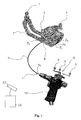
- FIG. 1 1 shows a calibration device 7, an instrument 9, a holder 10, a detection device 20 and a data processing device 30.
- the calibration device 7 comprises a marker device which has marker spheres 1, 2 and 3.
- the marker spheres 1, 2 and 3 are connected to each other via the body of the calibrating device 7 and occupy mutually predetermined relative positions.
- the body of the calibrator 7 preferably comprises openings. Of these openings, only the openings 8, 8a, 8b and 8c are provided with reference numerals for reasons of clarity.
- the openings are preferably cylindrical depressions having a known depth and a known diameter. Preferably, the openings differ in terms of their diameter.
- a code denoting the diameter of the opening is preferably printed adjacent to the opening.
- the instrument 9 is preferably elongated and flexible, in particular elastic.
- the instrument preferably has a circular cross-section. In the in FIG. 1 As shown, the instrument is strongly curved. In practical application, however, the instruments can be made considerably more rigid and allow only a slight curvature.
- the instruments are particularly made of stainless steel, as it is used in particular in medicine and surgery.
- the modulus of elasticity of steel is 190 GPa to 200 GPa.
- glass fiber is 50 GPa to 90 GPa, whereas against that of silicone rubber, for example, only 10 MPa to 100 MPa.
- the instrument may also have other diameters, such as rectangular diameters, for example in the case of a metal plate.
- Typical diameters are in the millimeter range of z. B. greater than 0.1 mm and / or less than 20 mm.
- instruments are ultrasound probes, cannulas, catheters, in particular for ventricular drainage and for use in pain therapy (for example, peridural anesthesia, in particular PDK) or needles, as used, for example, in vertibroplasty or facet infiltration.
- pain therapy for example, peridural anesthesia, in particular PDK
- needles as used, for example, in vertibroplasty or facet infiltration.
- the instrument 9 is fastened to the holder 10 at a mounting end 11 of the holder 10.
- the instrument 9 is inserted into a suitably formed sleeve which is provided at the mounting end 11, and for example, due to the accuracy of fit and / or by means of a screw with the holder 10 fixedly connected.
- a marker device 12 which has three marker balls 4, 5 and 6.
- the marker balls 4, 5 and 6 of the marker device 12 are connected to each other via arms so that they occupy a predetermined relative position to each other.
- Calibrator 7 and holder 10 are calibrated so that the relative locations of at least portions of the surface of holder 10 and calibrator 7 relative to the marker spheres are known.
- the relative position between the openings (8, 8a, 8b, 8c,...) Of the calibrating device 7 relative to the marker spheres 1, 2 and 3 is known.
- the relative position of the mounting end 11 relative to the marker means 12 is known.
- the data and information referred to above as known are stored in the data processing device 30.
- the relative positions of the marker spheres 1, 2 and 3 relative to the apertures and the relative positions of the marker spheres 4, 5 and 6 relative to the end 11 are stored in the data processing device 30.
- 30 data signals from the detector device 20 enter the data processing system.
- the detector device 20 detects signals from the marker spheres 1, 2, 3, 4, 5 and 6.
- the detection device 20 is designed as a camera which detects light, for example infrared light, emanating from the marker spheres, in particular reflected by them.
- the marker spheres reflect light if they have passive marker spheres are. In this case, they can be illuminated by continuous or pulsed light sources, for example, so that they reflect the light.
- the instruments used for the invention are preferably thin, d. H. the length is a multiple of the diameter, for example more than 2 times or 5 times or 10 times or 20 times the diameter.
- the geometry of the holder is stored in the computer 30, i. H. the relative position between the marker device 12 and the mounting end 11 is known.
- the mounting end 11 may be plugged into one of the openings 8, 8a, 8b or 8c in the calibrator, for example, until it comes in contact with the bottom of the holes. Since the depth and position (in particular geometry) of the holes is known and the relative position to the marker spheres 1, 2 and 3 is known, the relative position of the marker spheres 4, from the signals detected by the detection device 20 and further processed by the data processing device 30, 5 and 6, which are also detected, relative to the mounting end 11 are calculated by the data processing device 30.
- the instrument 9 is inserted into a preferably precisely fitting opening 8, so that the inner diameter of the opening 8 (at least approximately) coincides with the outer diameter of the instrument 9.
- the diameter of the opening 8 may be read by the calibrator by an operator and entered into the data processing device 30 for further processing.
- the determination of the diameter of the instrument 9 may also be automatic (without manual input by a user).
- the distance is significantly greater than the deflection with which the first end 9a of the instrument 9 can deviate from a position which occupies the first end 9a when the instrument 9 is rectilinear.
- the aforementioned openings may have a distance of, for example, 2 cm. If this is the case, the appropriate opening can be derived from the relative position between the marker device 12 and the calibration device 7.
- the data processing device 30 may determine from this relative position that only one of the openings is eligible for insertion of the instrument 9 therein has been.
- the other openings would require a significantly greater deflection of the instrument 9, but which is considered not real. How a practically possible deflection of the instrument 9 is calculated will be explained below.
- the data processing device preferably also processes information about the elasticity of the material of the instrument in addition to the information about the diameter of the instrument.
- the modulus of elasticity is used for this purpose.
- the modulus of elasticity is a material characteristic value from materials engineering, which describes the relationship between stress and strain in the deformation of a solid body with linear elastic behavior. The amount of elastic modulus is greater, the more resistance a material opposes to its deformation.
- the position of the first end 9a of the instrument is known, because this end 9a is inserted all the way into the matching opening 8.
- the position of the bottom of the opening 8 relative to the marker balls 1, 2 and 3 is also known and stored in the data processing device 30.
- the position of the first end 9a of the instrument 9 is known and can be further processed by the data processing device.
- the instrument 9 is also inserted all the way into the sleeve 11 (mounting end 11) of the holder 10.
- the relative position of the second end 9b relative to the marker device 12 is known.
- the position of the second end 9b is thus known.
- the following data is present in the data processing device 30 for further processing: the diameter of the instrument 9, the position of the ends 9a and 9b (for example relative to the detection device 20 in a frame of reference by which the detection device 20 rests) and the modulus of elasticity of the material of the instrument.
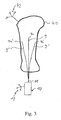
- the angle ⁇ is in FIG. 2 explained.
- the origin of the x, y coordinate system coincides with the bottom in the aperture 8 in the calibrator 7, with the first end of the instrument resting against the bottom.
- EI is the flexural rigidity of the instrument, where E is the modulus of elasticity and I depends on the geometry of the instrument and may be referred to as the cross-sectional moment of inertia.
- E the modulus of elasticity
- I depends on the geometry of the instrument and may be referred to as the cross-sectional moment of inertia.
- I the modulus of elasticity
- I the modulus of elasticity
- I the cross-sectional moment of inertia.
- I which differs from that mentioned above in the equation (1) results.
- the size "1" denotes the length from the first end 9a to a point P. The position of the point P can thus be described by the length 1 and by the angle ⁇ .
- the force acting on the end 9b at the point P e is the force F, which can be decomposed into two components F x (ie the component acting in the x-direction) and Fy (that is to say the component acting in y). It is assumed that the direction of the force F coincides with the tangent T described above. This is a realistic assumption, since with the help of the holder 10, the instrument 9 is to be introduced in practice, for example in a body structure, wherein on the instrument 9 in the direction of the tangent T with the holder 10 a compressive force is exerted to the instrument 9 on to advance in the body structure. It is therefore assumed that no bending forces and torques are exerted on the instrument 9, which can lead to a buckling of the instrument 9 at the assembly end 11 (ie at P e ).
- a force sensor is provided in the holding device 10.
- the force sensor is in particular in the vicinity of the mounting end 11.
- the force sensor preferably measures the amount of force that acts between the instrument 9 and the holder 10.
- the force gauge measures in particular the amount of force and preferably also the direction of the force. If the force sensor is provided, then the force F x and F y can be determined. Thus, from the above equations (2a) and (2b), ⁇ x and ⁇ y can be calculated. This simplifies the determination of the length L by means of equations (4) to (7).
- the instrument 9 for example a Kirschner wire, is inserted into a body structure (eg bone).
- a typical force F is exerted in the longitudinal direction of the instrument 9.
- typical forces used herein in the above calculation are greater than 0.1 N or 1 N or 10 N and, for example, less than 100 N or 1000 N.
- a typical force may be 1 N, for example.
- This assumed force has the magnitude F and is decomposed into the forces F x and F y for the above-mentioned calculation, where F x and F y are a function of F and ⁇ . Equation (4) thus allows the calculation of ⁇ e .
- equations (5) and (6) can then be used to calculate the position P e and thus the relative position between the first end and the second end of the instrument. Since the position of the second end of the instrument can be determined by detection of the marker device 12, the position of the first end of the instrument can be calculated by the data processing device 30 from this.
- the length of the instrument 9 is known and was, for example, with the aid of in FIG. 1 determined arrangement determined.
- the possible position of the first end 9a of the instrument can be calculated.
- the possible locations are in FIG. 3 9a, 9a 'and 9a ".
- the lines 9' and 9" denote the possible course of the instrument within the body structure 40 FIG. 3
- the data processing device 30 is connected to a display
- the z. B. shows the calibrated and registered body structure 40, which is connected for example with a marker device 42, and / or a cone with possible positions of the first end 9a, 9a 'and 9a''and / or possible progressions of the instrument according to the lines 9, 9' and 9 '' from the first end to the second end of the instrument or a portion of the possible courses.
- the surgeon is thus allowed, without the use of an X-ray machine, to assess the risk of getting into an undesired area with the end 9a.
Landscapes
- Health & Medical Sciences (AREA)
- Surgery (AREA)
- Life Sciences & Earth Sciences (AREA)
- Heart & Thoracic Surgery (AREA)
- Molecular Biology (AREA)
- Oral & Maxillofacial Surgery (AREA)
- Engineering & Computer Science (AREA)
- Biomedical Technology (AREA)
- Nuclear Medicine, Radiotherapy & Molecular Imaging (AREA)
- Medical Informatics (AREA)
- Pathology (AREA)
- Animal Behavior & Ethology (AREA)
- General Health & Medical Sciences (AREA)
- Public Health (AREA)
- Veterinary Medicine (AREA)
- Apparatus For Radiation Diagnosis (AREA)
- Length Measuring Devices With Unspecified Measuring Means (AREA)
Priority Applications (3)
| Application Number | Priority Date | Filing Date | Title |
|---|---|---|---|
| EP06023012A EP1925265B1 (fr) | 2006-11-06 | 2006-11-06 | Détermination de la longeur d'un instrument longue et flexible |
| DE502006005876T DE502006005876D1 (de) | 2006-11-06 | 2006-11-06 | Längenbestimmung eines flexiblen, langen Instruments |
| US11/935,571 US20080139916A1 (en) | 2006-11-06 | 2007-11-06 | Determining the length of a long, flexible instrument |
Applications Claiming Priority (1)
| Application Number | Priority Date | Filing Date | Title |
|---|---|---|---|
| EP06023012A EP1925265B1 (fr) | 2006-11-06 | 2006-11-06 | Détermination de la longeur d'un instrument longue et flexible |
Publications (2)
| Publication Number | Publication Date |
|---|---|
| EP1925265A1 true EP1925265A1 (fr) | 2008-05-28 |
| EP1925265B1 EP1925265B1 (fr) | 2010-01-06 |
Family
ID=37890387
Family Applications (1)
| Application Number | Title | Priority Date | Filing Date |
|---|---|---|---|
| EP06023012A Not-in-force EP1925265B1 (fr) | 2006-11-06 | 2006-11-06 | Détermination de la longeur d'un instrument longue et flexible |
Country Status (3)
| Country | Link |
|---|---|
| US (1) | US20080139916A1 (fr) |
| EP (1) | EP1925265B1 (fr) |
| DE (1) | DE502006005876D1 (fr) |
Cited By (2)
| Publication number | Priority date | Publication date | Assignee | Title |
|---|---|---|---|---|
| CN112716605A (zh) * | 2021-03-31 | 2021-04-30 | 上海龙慧医疗科技有限公司 | 球窝式定位器双向自锁杆 |
| US20230045275A1 (en) * | 2021-08-05 | 2023-02-09 | GE Precision Healthcare LLC | Methods and system for guided device insertion during medical imaging |
Families Citing this family (11)
| Publication number | Priority date | Publication date | Assignee | Title |
|---|---|---|---|---|
| US9449149B2 (en) | 2011-05-11 | 2016-09-20 | Brainlab Ag | Method for optimising local drug delivery |
| US10292775B2 (en) * | 2011-08-26 | 2019-05-21 | Brainlab Ag | Systems and method for determining the shape of a surgical instrument and surgical instruments having a deformable body |
| US20140235999A1 (en) * | 2011-08-26 | 2014-08-21 | Brainlab Ag | Method for determining the shape of a surgical instrument and surgical instrument having a deformable body |
| US8668344B2 (en) | 2011-11-30 | 2014-03-11 | Izi Medical Products | Marker sphere including edged opening to aid in molding |
| US8661573B2 (en) | 2012-02-29 | 2014-03-04 | Izi Medical Products | Protective cover for medical device having adhesive mechanism |
| US9468504B2 (en) * | 2013-02-27 | 2016-10-18 | B & D Dental Corporation | Dental cutting system and method with remote cutting guide |
| DE202013012313U1 (de) | 2013-07-17 | 2016-02-25 | Fiagon Gmbh | Vorrichtung zur Anbindung eines medizinischen Instruments an ein Lageerfassungssystem und medizinisches Zeigerinstrument |
| DE102013222230A1 (de) | 2013-10-31 | 2015-04-30 | Fiagon Gmbh | Chirurgisches Instrument |
| CN108024693B (zh) * | 2015-09-10 | 2021-07-09 | 直观外科手术操作公司 | 在图像引导医疗程序中利用跟踪的系统和方法 |
| EP3719749B1 (fr) | 2019-04-03 | 2026-01-14 | Fiagon GmbH | Procédé et configuration d'enregistrement |
| CN111110351B (zh) * | 2020-01-10 | 2021-04-30 | 北京天智航医疗科技股份有限公司 | 用于检测关节置换手术机器人系统精度的组件和方法 |
Citations (3)
| Publication number | Priority date | Publication date | Assignee | Title |
|---|---|---|---|---|
| US5921992A (en) * | 1997-04-11 | 1999-07-13 | Radionics, Inc. | Method and system for frameless tool calibration |
| WO2002036018A1 (fr) * | 2000-11-03 | 2002-05-10 | Synthes Ag Chur | Determination de deformations d'instruments chirurgicaux |
| EP1704825A1 (fr) * | 2005-03-22 | 2006-09-27 | BrainLAB AG | Navigation de fil de guidage |
Family Cites Families (4)
| Publication number | Priority date | Publication date | Assignee | Title |
|---|---|---|---|---|
| US5122150A (en) * | 1985-03-27 | 1992-06-16 | Puig Ana E | Neurosurgical clip applier |
| US5913820A (en) * | 1992-08-14 | 1999-06-22 | British Telecommunications Public Limited Company | Position location system |
| US6351659B1 (en) * | 1995-09-28 | 2002-02-26 | Brainlab Med. Computersysteme Gmbh | Neuro-navigation system |
| US6497152B2 (en) * | 2001-02-23 | 2002-12-24 | Paroscientific, Inc. | Method for eliminating output discontinuities in digital pressure transducers and digital pressure transducer employing same |
-
2006
- 2006-11-06 DE DE502006005876T patent/DE502006005876D1/de active Active
- 2006-11-06 EP EP06023012A patent/EP1925265B1/fr not_active Not-in-force
-
2007
- 2007-11-06 US US11/935,571 patent/US20080139916A1/en not_active Abandoned
Patent Citations (3)
| Publication number | Priority date | Publication date | Assignee | Title |
|---|---|---|---|---|
| US5921992A (en) * | 1997-04-11 | 1999-07-13 | Radionics, Inc. | Method and system for frameless tool calibration |
| WO2002036018A1 (fr) * | 2000-11-03 | 2002-05-10 | Synthes Ag Chur | Determination de deformations d'instruments chirurgicaux |
| EP1704825A1 (fr) * | 2005-03-22 | 2006-09-27 | BrainLAB AG | Navigation de fil de guidage |
Cited By (4)
| Publication number | Priority date | Publication date | Assignee | Title |
|---|---|---|---|---|
| CN112716605A (zh) * | 2021-03-31 | 2021-04-30 | 上海龙慧医疗科技有限公司 | 球窝式定位器双向自锁杆 |
| CN112716605B (zh) * | 2021-03-31 | 2021-06-11 | 上海龙慧医疗科技有限公司 | 球窝式定位器双向自锁杆 |
| US20230045275A1 (en) * | 2021-08-05 | 2023-02-09 | GE Precision Healthcare LLC | Methods and system for guided device insertion during medical imaging |
| US12108993B2 (en) * | 2021-08-05 | 2024-10-08 | GE Precision Healthcare LLC | Methods and system for guided device insertion during medical imaging |
Also Published As
| Publication number | Publication date |
|---|---|
| US20080139916A1 (en) | 2008-06-12 |
| DE502006005876D1 (de) | 2010-02-25 |
| EP1925265B1 (fr) | 2010-01-06 |
Similar Documents
| Publication | Publication Date | Title |
|---|---|---|
| DE69738092T2 (de) | Krümmungsempfindlicher Katheter | |
| DE69112538T2 (de) | Computerunterstützte chirurgische Vorrichtung. | |
| EP1593350B1 (fr) | Localisation d'un clou centromedullaire | |
| EP1925265B1 (fr) | Détermination de la longeur d'un instrument longue et flexible | |
| EP1872735B1 (fr) | Procédé d'identification automatique d'instruments lors de navigation médicale | |
| DE102006032127B4 (de) | Kalibrierverfahren und Kalibriervorrichtung für eine chirurgische Referenzierungseinheit | |
| EP1089669B1 (fr) | Alignement de reference a l'aide de vis de repere | |
| DE102005042751B4 (de) | System, Einrichtung und Verfahren zum Ad-hoc-Nachverfolgen eines Objektes | |
| DE2443558B2 (de) | Vorrichtung zum Punktieren von körperinternen Organen und Gefäßen | |
| EP1886641A1 (fr) | Méthode et système pour la détermination de la position relative d'un instrument medical par rapport à une structure corporelle | |
| EP2105107A1 (fr) | Procédé de calibrage pour instruments médicinaux ou médicaux déterminés par des axes | |
| WO2019101862A1 (fr) | Dispositif de guidage pour une aiguille de biopsie | |
| DE102004044285A1 (de) | System und Verfahren zum Bestimmen der Position eines in einem Positionsverfolgungssystems verwendeten elastischen Instruments | |
| DE19536180C2 (de) | Verfahren und Vorrichtungen zur Lokalisierung eines Instruments | |
| EP1923015A1 (fr) | Système de navigation avec marquers pour obtenir et representer leur position | |
| EP2051096A2 (fr) | Procédé et dispositif de détermination de la surface frontale de la hanche | |
| DE102011083360A1 (de) | Instrument zur Pedikelpräparation mit Ultraschallsonde | |
| DE19908844A1 (de) | Verfahren und Vorrichtung zur Korrelation der tatsächlichen Lage eines Markierungselementes mit den durch ein Abbildungsverfahren erhaltenen Positionsdaten | |
| DE102009017243B4 (de) | System zur Bestimmung von Abweichungen der vorherbestimmten Lage eines unsichtbaren Merkmals aufgrund von Verformungen bei Implantaten | |
| EP3459478B1 (fr) | Dispositif de mise en forme technique médical, système de mise en forme et procédé de mise en forme d'un article | |
| DE102005047895A1 (de) | Verfahren und Einrichtung zur Bestimmung der Lage eines Gegenstandes | |
| DE102014200326A1 (de) | Verfahren zum Unterstützen einer Navigation eines medizinischen Instruments | |
| DE10241071B4 (de) | Vorrichtung zum Lokalisieren bestimmter Substanzen in einem tierischen oder menschlichen Körper | |
| DE102010042012A1 (de) | Instrument mit Ultraschallsonde zur Pedikelpräparation | |
| EP1369090B1 (fr) | Etalonnage d'un système de navigation pour instruments et d'implants chirurgicaux |
Legal Events
| Date | Code | Title | Description |
|---|---|---|---|
| PUAI | Public reference made under article 153(3) epc to a published international application that has entered the european phase |
Free format text: ORIGINAL CODE: 0009012 |
|
| 17P | Request for examination filed |
Effective date: 20061106 |
|
| AK | Designated contracting states |
Kind code of ref document: A1 Designated state(s): AT BE BG CH CY CZ DE DK EE ES FI FR GB GR HU IE IS IT LI LT LU LV MC NL PL PT RO SE SI SK TR |
|
| AX | Request for extension of the european patent |
Extension state: AL BA HR MK RS |
|
| AKX | Designation fees paid |
Designated state(s): DE FR |
|
| GRAP | Despatch of communication of intention to grant a patent |
Free format text: ORIGINAL CODE: EPIDOSNIGR1 |
|
| GRAS | Grant fee paid |
Free format text: ORIGINAL CODE: EPIDOSNIGR3 |
|
| GRAA | (expected) grant |
Free format text: ORIGINAL CODE: 0009210 |
|
| AK | Designated contracting states |
Kind code of ref document: B1 Designated state(s): DE FR |
|
| REF | Corresponds to: |
Ref document number: 502006005876 Country of ref document: DE Date of ref document: 20100225 Kind code of ref document: P |
|
| PLBE | No opposition filed within time limit |
Free format text: ORIGINAL CODE: 0009261 |
|
| STAA | Information on the status of an ep patent application or granted ep patent |
Free format text: STATUS: NO OPPOSITION FILED WITHIN TIME LIMIT |
|
| 26N | No opposition filed |
Effective date: 20101007 |
|
| REG | Reference to a national code |
Ref country code: DE Ref legal event code: R082 Ref document number: 502006005876 Country of ref document: DE Representative=s name: SCHWABE SANDMAIR MARX, DE |
|
| REG | Reference to a national code |
Ref country code: DE Ref legal event code: R081 Ref document number: 502006005876 Country of ref document: DE Owner name: BRAINLAB AG, DE Free format text: FORMER OWNER: BRAINLAB AG, 85622 FELDKIRCHEN, DE Effective date: 20131104 Ref country code: DE Ref legal event code: R082 Ref document number: 502006005876 Country of ref document: DE Representative=s name: SCHWABE SANDMAIR MARX, DE Effective date: 20131104 Ref country code: DE Ref legal event code: R082 Ref document number: 502006005876 Country of ref document: DE Representative=s name: SCHWABE SANDMAIR MARX PATENTANWAELTE RECHTSANW, DE Effective date: 20131104 |
|
| PGFP | Annual fee paid to national office [announced via postgrant information from national office to epo] |
Ref country code: FR Payment date: 20141119 Year of fee payment: 9 Ref country code: DE Payment date: 20141119 Year of fee payment: 9 |
|
| REG | Reference to a national code |
Ref country code: DE Ref legal event code: R119 Ref document number: 502006005876 Country of ref document: DE |
|
| REG | Reference to a national code |
Ref country code: FR Ref legal event code: ST Effective date: 20160729 |
|
| PG25 | Lapsed in a contracting state [announced via postgrant information from national office to epo] |
Ref country code: DE Free format text: LAPSE BECAUSE OF NON-PAYMENT OF DUE FEES Effective date: 20160601 |
|
| PG25 | Lapsed in a contracting state [announced via postgrant information from national office to epo] |
Ref country code: FR Free format text: LAPSE BECAUSE OF NON-PAYMENT OF DUE FEES Effective date: 20151130 |