EP1925239B1 - Corner cupboard - Google Patents
Corner cupboard Download PDFInfo
- Publication number
- EP1925239B1 EP1925239B1 EP07019007.9A EP07019007A EP1925239B1 EP 1925239 B1 EP1925239 B1 EP 1925239B1 EP 07019007 A EP07019007 A EP 07019007A EP 1925239 B1 EP1925239 B1 EP 1925239B1
- Authority
- EP
- European Patent Office
- Prior art keywords
- shelf
- lever
- corner cupboard
- tray
- corner
- Prior art date
- Legal status (The legal status is an assumption and is not a legal conclusion. Google has not performed a legal analysis and makes no representation as to the accuracy of the status listed.)
- Active
Links
Images


Classifications
-
- A—HUMAN NECESSITIES
- A47—FURNITURE; DOMESTIC ARTICLES OR APPLIANCES; COFFEE MILLS; SPICE MILLS; SUCTION CLEANERS IN GENERAL
- A47B—TABLES; DESKS; OFFICE FURNITURE; CABINETS; DRAWERS; GENERAL DETAILS OF FURNITURE
- A47B81/00—Cabinets or racks specially adapted for other particular purposes, e.g. for storing guns or skis
- A47B81/002—Corner cabinets; Cabinets designed for being placed in a corner or a niche
Definitions
- the invention relates to a corner cabinet, in particular causaleck O, with a cabinet body and an accessible via a corner door interior in which at least one tray by means of a fitting between an inner position and an outer position in which the tray is at least partially beyond a plane of a door opening of the corner cabinet, is movably guided.
- a corner cabinet of this kind is from the DE 20 2004 011 200 U1 known, in which a respective tray of two articulated on its underside of the handlebars is supported, wherein the first link is pivotable about a pivot axis of a support column and the second link about an axis parallel to the pivot axis of the support column axis of a support bearing.
- the tray is controlled by both handlebars together between the inner and the outer position.
- the object of the invention is to provide a corner cabinet of the type mentioned, with which the handling of a tray is simplified compared to the aforementioned prior art.
- the corner cabinet according to the invention is characterized in that a retraction device is provided for supporting or independent execution of a directed from the outer to the inner position of the tray retraction movement and a Auszug noise to support or autonomous execution of a directed from the inner to the outer position of the tray extension movement.
- a retraction device and / or extension device which supports the operator when retracting or extending the tray or independently assumes this retraction or extension movement even at a certain point of the retraction or extension path. This leads to a substantial relief in the operation of the tray.
- the tray between the inner and outer position performs a non-linear, for example, S-shaped or circular-like tablature movement.
- the intake device and extension device is associated with at least one energy storage device which is arranged between two in the tableau movement relative to each other movable points of the corner cabinet.
- the movable points can on the one hand on the cabinet periphery and on the other hand on the fitting or alternatively on two be provided relatively moving fitting parts.
- the energy storage is formed by a spring unit.
- a spring unit for example, at least one coil spring and / or at least one gas spring comes into consideration.
- a damping device for damping the Tablarterrorism when retracting into the inner position and / or extension is provided in the outer position.
- the damping device can be arranged or arranged between two positions of the corner cupboard which are movable relative to one another during the tabletting movement.
- two relatively movable fitting parts of the fitting are suitable for this purpose.
- the lever arrangements can each be formed by a single one-piece lever. Alternatively, it is possible that at least one of the lever arrangements is designed such that the distance between its bearing point and a fixed fixed pivot axis during tabla movement between the inner and outer position changes.
- FIGS. 1 to 10 show a preferred embodiment of the corner cabinet 11 according to the invention.
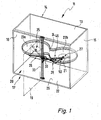
- the corner cabinet 11 has a cabinet body 13, which is shown by way of example with a rectangular plan.
- the cabinet body 13 in turn consists of a rear wall 14, two side walls 15, 16 and a front side 17, which in turn is subdivided into a front wall 18 and a corner cabinet door 19 arranged adjacent thereto. Furthermore, a cabinet bottom 29 is provided. Front wall 18 and corner door 19 occupy the front 17 in approximately equal parts.
- the rectangular cabinet body 13 defines a correspondingly rectangular interior 20, which is accessible in about half the corner cabinet door 19. As a rule, further cabinet parts are attached to the front wall 18 and to the side wall 15 adjacent to the door opening.
- a doorway of the corner cupboard 11 is controlled movably.
- a single shelf 21 is accommodated in the corner cabinet 11.
- two or more superposed shelves could be arranged in the corner cabinet 11, which are preferably arranged one above the other in alignment in their respective inner or outer position.
- the tray 21 is exemplified in one-piece embodiment. However, it is also possible to use multi-part trays.
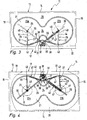
- the floor plan of the tray 21 is exemplified in the form of an eight.
- two substantially circular tray sections 23a, 23b are provided, which are connected to one another via a smaller diameter intermediate section 24.
- the tray 21 is fitted in the middle, so to speak.
- the sidecut is therefore provided so that the tray 21 in the tableau movement described below in more detail without hindrance from the cabinet periphery out of the door opening and can go beyond the adjacent to the door opening side wall 15 out into the open position.
- the tray 21 is supported at a first bearing point 25 by a first lever arrangement 26 and at a second bearing point 27 spaced from the first bearing point 25 by a second lever arrangement 28.
- the lever arrangements 26, 28 are mounted at their respective bearing points 25, 27 articulated on the underside of the tray 21.
- Both lever assemblies 26, 28 are on the one hand to a common stationary, located in the vicinity of the door opening pivot axis 30 pivotally and on the other hand at the associated bearing point 25, 27 hingedly connected to the tray 21.
- both lever assemblies 26, 28 are formed such that the distance between their respective bearing point 25, 27 and the pivot axis 30 in the Tablarmony between the inner and outer position changes. That is, the lever length of the lever assemblies 26, 28 shortens or lengthens during the tableau movement.
- one of the lever assemblies is equipped with variable lever length, while in the other lever assembly, the distance between its bearing on the shelf and the pivot axis in the Tablar Gay Gay Gay between the inner and outer position is constant. This can be achieved for example by a single one-piece lever, which is hinged to the bearing on the tray.
- the pivot axis 30 is located on a particular plate-like support unit 31, which in turn is fastened via a fastener 32 on the cabinet bottom 29, on an upper cabinet cover or on the inside of the front wall 18, in particular.dort on a vertical strut 33.
- a fastener 32 on the cabinet bottom 29, on an upper cabinet cover or on the inside of the front wall 18, in particular.dort on a vertical strut 33.
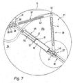
- a respective lever arrangement 26, 28 has two levers 36, 37, of which a first lever 36 is pivotally mounted on the pivot axis 30 and serves as part of a sliding guide for a second lever 37.
- the second lever 37 is hinged to the associated bearing point 25, 27 on the tray 21 and at the same time displaceably guided on the first lever 36, wherein On the other hand, it is pivotally connected to the first lever 36 on a tabletting movement at a constant distance from the pivot axis 30 located hinge point 38 and at the same time guided with its lever end 39 on the associated control cam 34, 35.
- the second lever 37 is hinged to the tray 21 as already mentioned.
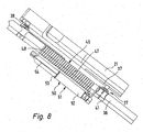
- the first lever 36 may be tubular, on which a kind of guide bushing 41 is movably guided, which in turn is connected to the second lever 37.
- the second lever 37 is designed as a toggle lever and has a second lever arm 44, which is articulated on the one hand on the guide bush 41 and the other hand connected via a hinge point 43 with a first lever arm 42, in turn, on the other hand articulated via the hinge point 38 to the first lever 36 is.
- this situation is the same on both lever assemblies 26, 28, ie
- Each lever arrangement is associated with a control cam 34, 35 whose eccentric curve courses the distance between the respective bearing points 25, 27 and the pivot axis 30 control during the tableau movement between the indoor and outdoor position.
- a retraction device 46 is provided for supporting or autonomously executing a closing movement directed from the outer to the inner position of the tray 21 and an extension device for supporting or independently executing an opening movement directed from the inner to the outer position of the tray 21.
- the retraction device 46 is also the extraction device at the same time.
- the entry and exit device 46 has at least one energy store in the form of a spring unit 47, which is arranged between two in the Tablarterrorism relatively movable points of the corner cabinet 11.
- At least one helical spring is provided in a preferred manner, on the one hand fixed to the first lever 36, for example, attached to a pivot point 38 carrier plate 48, and on the other hand with the associated bearing point 25, 27 coupled to the guide bush 41, for example ,
- the respective cam 34, 35 has, as mentioned, an eccentric curve with a dead center 49, which causes the lever length after shortening from the dead center again extended. This is done both in the Tablarterrorism from the inner to the outer position and in the Tablarterrorism from the outer to the inner position.
- the coil spring is thus stretched or relaxed during shortening or lengthening of the lever length, which results in that the spring force of the coil spring is provided to support or autonomous execution of Tablariolo in the inner position and support or independent execution of Tablarterrorism in the outer position.
- damping device 50 for damping the Tablarterrorism when entering the inner position and / or extending into the outer position.
- the damping device 50 can be arranged between two positions of the corner cabinet 11 which are movable relative to one another during the tableau movement, for example, also being fixedly connected on one side to the first lever 36 and 27 on the other hand being movably coupled to the associated bearing point 25, 27.
- the damping device 50 has a damping cylinder 51, which in turn has a cylinder housing 52 and a slidably mounted therein damping piston 53, which in turn is connected to a'Kolbenstange 54, the piston remote end of the first lever 36, in particular as the coil spring on the support plate 48th , is attached.
- the damping piston 53 is either extended or retracted into the cylinder housing 52, whereby the air contained therein is displaced during the extension of the damping piston 53, which leads to the damping of the tableau movement.
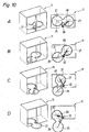
- FIGS. 10A to 10D the movement situation of the tray 21 is illustrated in the Tablarnism between the inner and the outer position.
- the tray 21 is initially in the inner position, completely housed in the interior 20 of the corner cupboard 11.
- the corner cabinet door 19 is opened and the tray 21 is pulled out a little bit with its door opening next tray section 23 b from the door opening.
- FIG. 10B shows.
- the lever length of both the first and the second lever arrangement 26, 28 shortens.
- the distance between the two bearing points 25, 27 to the pivot axis 30 is thus reduced.
- the coil spring of the spring unit 47 is tensioned, that is, a total must also worked against this spring force become.
- the tray then reaches the in FIG. 10C shown position in which the dead centers of the respective, the lever assemblies 26, 28 associated control cams 34, 35 are already run over.
- the lever lengths of the two lever assemblies 26, 28 have therefore extended again, ie, the distance between the respective bearing points 25, 27 and the pivot axis 30 has become larger again.
- the coil spring of the spring unit 47 relaxes and provides previously stored spring force for the further movement of the tray in the Figure 10D shown external position available. In this external position more than half of the tray 21 is arranged outside the corner cupboard 11. The determination of this external position is done, inter alia, that the run on the control cams 34, 35 guide pin to the end of the cams 34, 35 reach where there is a stop beyond which a further movement is not possible. In the outer position of the toggle lever of the first lever assembly 26 is almost stretched and thus has its largest lever length.
Landscapes
- Combinations Of Kitchen Furniture (AREA)
Description
Die Erfindung betrifft einen Eckschrank, insbesondere Kücheneckschrank, mit einem Schrankkorpus und einem über eine Eckschranktür zugänglichen Innenraum, in dem wenigstens ein Tablar mittels eines Beschlages zwischen einer Innenstellung und einer Außenstellung, in der das Tablar zumindest teilweise über eine Ebene einer Türöffnung des Eckschranks hinaussteht, beweglich geführt ist.The invention relates to a corner cabinet, in particular Kücheneckschrank, with a cabinet body and an accessible via a corner door interior in which at least one tray by means of a fitting between an inner position and an outer position in which the tray is at least partially beyond a plane of a door opening of the corner cabinet, is movably guided.
Ein Eckschrank dieser Art ist aus der
Aufgabe der Erfindung ist es, einen Eckschrank der eingangs erwähnten Art zu schaffen, mit dem die Handhabung eines Tablars im Vergleich zu dem vorerwähnten Stand der Technik vereinfacht ist.The object of the invention is to provide a corner cabinet of the type mentioned, with which the handling of a tray is simplified compared to the aforementioned prior art.
Diese Aufgabe wird durch einen Eckscrank mit den Merkmalen des unabhängigen Anspruchs 1 gelöst. Weiterbildungen der Erfindung sind in den Unteransprüchen dargestellt.This object is achieved by a Eckscrank with the features of
Der erfindungsgemäße Eckschrank zeichnet sich dadurch aus, dass eine Einzugeinrichtung zur Unterstützung oder selbstständigen Ausführung einer von der Außen- zur Innenstellung des Tablars gerichteten Einfahrbewegung und eine Auszugeinrichtung zur Unterstützung oder selbstständigen Ausführung einer von der Innen- zur Außenstellung des Tablars gerichteten Ausfahrbewegung vorgesehen ist.The corner cabinet according to the invention is characterized in that a retraction device is provided for supporting or independent execution of a directed from the outer to the inner position of the tray retraction movement and a Auszugeinrichtung to support or autonomous execution of a directed from the inner to the outer position of the tray extension movement.
Insbesondere bei einem einteiligen, ein relativ großes Eigengewicht aufweisenden Tablar, auf dem möglicherweise noch eine Vielzahl an Gegenständen abgestellt ist, ist es mühsam, das Tablar den gesamten Weg von der Außenstellung in die Innenstellung und umgekehrt händisch zu bewegen. Um diesem Problem abzuhelfen, ist eine Einzugeinrichtung und/oder Auszugeinrichtung vorgesehen, die den Bediener beim Ein- oder Ausfahren des Tablars unterstützt oder diese Einfahr- bzw. Ausfahrbewegung sogar ab einem bestimmten Punkt des Einfahr- bzw. Ausfahrwegs selbstständig übernimmt. Dies führt zu einer wesentlichen Erleichterung bei der Bedienung des Tablars.In particular, in a one-piece, a relatively large own weight having tray on which may still be parked a variety of items, it is tedious to move the tray all the way from the outer position to the inner position and vice versa by hand. In order to remedy this problem, a retraction device and / or extension device is provided which supports the operator when retracting or extending the tray or independently assumes this retraction or extension movement even at a certain point of the retraction or extension path. This leads to a substantial relief in the operation of the tray.
Vorzugsweise führt das Tablar zwischen der Innen- und Außenstellung eine nichtlineare, beispielsweise S-förmige oder kreisbahnartige Tablarbewegung aus.Preferably, the tray between the inner and outer position performs a non-linear, for example, S-shaped or circular-like tablature movement.
Bei der Erfindung ist der Einzugteinrichtung und Auszugeinrichtung wenigstens ein Kraftspeicher zugeordnet, der zwischen zwei bei der Tablarbewegung relativ zueinander bewegbaren Stellen des Eckschranks angeordnet ist. Die bewegbaren Stellen können einerseits an der Schrankperipherie und andererseits am Beschlag oder alternativ an zwei sich relativ zueinander bewegenden Beschlagteilen vorgesehen sein.In the invention, the intake device and extension device is associated with at least one energy storage device which is arranged between two in the tableau movement relative to each other movable points of the corner cabinet. The movable points can on the one hand on the cabinet periphery and on the other hand on the fitting or alternatively on two be provided relatively moving fitting parts.
Die Einzugeinrichtungt und Auszugeinrichtung weisen gemeinsam den Kraftspeicher aufThe Einggeinrichtungt and pullout together have the energy storage
Der Kraftspeicher wird von einer Federeinheit gebildet. Als Federeinheit kommt beispielsweise wenigstens eine Schraubenfeder und/oder wenigstens eine Gasfeder in Betracht.The energy storage is formed by a spring unit. As a spring unit, for example, at least one coil spring and / or at least one gas spring comes into consideration.
Bei einer Weiterbildung der Erfindung ist eine Dämpfungseinrichtung zur Dämpfung der Tablarbewegung beim Einfahren in die Innenstellung und/oder Ausfahren in die Außenstellung vorgesehen. Die Dämpfungseinrichtung kann zwischen zwei bei der Tablarbewegung relativ zueinander bewegbaren Stellen des Eckschranks anordnenbar bzw. angeordnet sein. Dafür eignen sich beispielsweise wiederum zwei relativ zueinander bewegbare Beschlagteile des Beschlags.In a further development of the invention, a damping device for damping the Tablarbewegung when retracting into the inner position and / or extension is provided in the outer position. The damping device can be arranged or arranged between two positions of the corner cupboard which are movable relative to one another during the tabletting movement. For example, two relatively movable fitting parts of the fitting are suitable for this purpose.
Zur Steuerung der Tablarbewegung zwischen der Innen- und der Außenstellung kann eine an einer ersten Lagerstelle an das Tablar angelenkte erste Hebelanordnung und eine an einer von der ersten Lagerstelle beabstandeten zweiten Lagerstelle an das Tablar angelenkte zweite Hebelanordnung vorgesehen sein. Die Hebelanordnungen können jeweils von einem einzelnen einteiligen Hebel gebildet werden. Alternativ ist es möglich, dass wenigstens eine der Hebelanordnungen derart ausgebildet ist, dass sich der Abstand zwischen ihrer Lagerstelle und einer ortfesten Schwenkachse bei der Tablarbewegung zwischen der Innen- und Außenstellung ändert.For controlling the Tablarbewegung between the inner and the outer position may be provided at a first bearing point to the tray articulated first lever assembly and a hinged at one of the first bearing second bearing point to the tray second lever arrangement. The lever arrangements can each be formed by a single one-piece lever. Alternatively, it is possible that at least one of the lever arrangements is designed such that the distance between its bearing point and a fixed fixed pivot axis during tabla movement between the inner and outer position changes.
Bevorzugte Ausführungsbeispiele der Erfindung sind in der Zeichnung dargestellt und werden im Folgenden näher erläutert. In der Zeichnung zeigen:
Figur 1- eine perspektivische Darstellung eines bevorzugten Ausführungsbeispiels des erfindungsgemäßen Eckschranks,
- Figur 2
- eine Vorderansicht des Eckschranks von
Figur 1 - Figur 3
- eine Draufsicht auf den Eckschrank von
Figur 1 - Figur 4
- eine teilweise geschnittene Ansicht von unten auf den Eckschrank von
Figur 1 - Figur 5
- eine teilweise geschnittene Ansicht von links auf den Eckschrank von
Figur 1 - Figur 6
- eine teilweise geschnittene Ansicht von rechts auf den Eckschrank von
Figur 1 - Figur 7
- eine vergrößerte Darstellung der Einzelheit X von
Figur 4 , - Figur 8
- eine Seitenansicht der Darstellung von
Figur 7 , - Figur 9
- eine vergrößerte Darstellung der Einzelheit Y von
Figur 4 , - Figur 10
- in vier aufeinander folgenden Schritten A-D die Tablarbewegung zwischen der Innenstellung und der Außenstellung.
- FIG. 1
- a perspective view of a preferred embodiment of the invention Eckschranks,
- FIG. 2
- a front view of the corner cupboard of
FIG. 1 . - FIG. 3
- a top view of the corner cabinet of
FIG. 1 . - FIG. 4
- a partially cut view from below of the corner cupboard of
FIG. 1 . - FIG. 5
- a partially cutaway view from the left onto the corner cupboard of
FIG. 1 . - FIG. 6
- a partially sectioned view from the right onto the corner cupboard of
FIG. 1 . - FIG. 7
- an enlarged view of the detail X of
FIG. 4 . - FIG. 8
- a side view of the representation of
FIG. 7 . - FIG. 9
- an enlarged view of the detail Y of
FIG. 4 . - FIG. 10
- in four consecutive steps AD the tableau movement between the inside position and the outside position.
Die
Im Innenraum 20 des Eckschranks 11 befindet sich wenigstens ein Tablar 21, das mittels des Beschlags 12 zwischen einer Innenstellung, in der das Tablar 21 vollständig im Innenraum 20 untergebracht ist, und einer Außenstellung, in der das Tablar 21 zumindest teilweise über eine Ebene 22 einer Türöffnung des Eckschranks 11 hinaussteht (siehe
Gemäß dem bevorzugten Ausführungsbeispiel ist im Eckschrank 11 ein einzelnes Tablar 21 untergebracht. Dies ist jedoch lediglich beispielhaft. Genauso gut könnten im Eckschrank 11 zwei oder mehr übereinanderliegende Tablare angeordnet sein, die vorzugsweise in ihrer jeweiligen Innen- bzw. Außenstellung fluchtend übereinander angeordnet sind. Ferner ist das Tablar 21 beispielhaft in einteiliger Ausführungsform dargestellt. Es ist jedoch auch möglich, mehrteilige Tablare einzusetzen.According to the preferred embodiment, a
Auch der Grundriss des Tablars 21 ist beispielhaft in Form einer Acht dargestellt. In diesem Fall sind zwei im Wesentlichen kreisrunde Tablarabschnitte 23a, 23b vorgesehen, die über einen durchmesserkleineren Zwischenabschnitt 24 miteinander verbunden sind. Das Tablar 21 ist sozusagen in der Mitte tailliert. Die Taillierung ist deshalb vorgesehen, damit das Tablar 21 bei der nachfolgend noch näher beschriebenen Tablarbewegung ohne Behinderung seitens der Schrankperipherie aus der Türöffnung herausfahren und über die an die Türöffnung angrenzende Seitenwand 15 hinaus in die Außenstellung fahren kann.Also, the floor plan of the
Das Tablar 21 wird an einer ersten Lagerstelle 25 von einer ersten Hebelanordnung 26 und an einer von der ersten Lagerstelle 25 beabstandeten zweiten Lagerstelle 27 von einer zweiten Hebelanordnung 28 abgestützt. Die Hebelanordnungen 26, 28 sind an ihren jeweiligen Lagerstellen 25, 27 gelenkig an der Unterseite des Tablars 21 gelagert.The
Beide Hebelanordnungen 26, 28 sind einerseits um eine gemeinsame ortsfeste, in der Nähe der Türöffnung liegende Schwenkachse 30 schwenkbar und andererseits an der zugeordneten Lagerstelle 25, 27 gelenkig mit dem Tablar 21 verbunden. Gemäß dem bevorzugten Ausführungsbeispiel sind beide Hebelanordnungen 26, 28 derart ausgebildet, dass der Abstand zwischen ihrer jeweiligen Lagerstelle 25, 27 und der Schwenkachse 30 bei der Tablarbewegung zwischen der Innen- und Außenstellung sich ändert. Das heißt, die Hebellänge der Hebelanordnungen 26, 28 verkürzt oder verlängert sich bei der Tablarbewegung. Bei einem nicht dargestellten alternativen Ausführungsbeispiel ist eine der Hebelanordnungen mit variabler Hebellänge ausgestattet, während bei der anderen Hebelanordnung der Abstand zwischen ihrer Lagerstelle am Tablar und der Schwenkachse bei der Tablarbewegung zwischen der Innen- und Außenstellung konstant ist. Dies kann beispielsweise durch einen einzelnen einteiligen Hebel erzielt werden, der an der Lagerstelle am Tablar angelenkt ist.Both
Die Schwenkachse 30 befindet sich an einer insbesondere plattenartig ausgebildeten Trageinheit 31, die ihrerseits über ein Befestigungselement 32 am Schrankboden 29, an einer oberen Schrankabdeckung oder an der Innenseite der Vorderwand 18, insbesondere.dort an einer Vertikalstrebe 33 befestigt ist. An der Trageinheit 31 sind zwei, jeweils einer der beiden Hebelanordnungen 26, 28 zugeordnete Steuerkurven 34, 35 ausgebildet, die in nachfolgend näher beschriebener Weise die Hebelanordnungen 26, 28 steuern und damit für die Verkürzung bzw. Verlängerung der Hebellänge zuständig sind.The
Eine jeweilige Hebelanordnung 26, 28 besitzt zwei Hebel 36, 37, von denen ein erster Hebel 36 an der Schwenkachse 30 schwenkbar gelagert ist und als Teil einer Schiebeführung für einen zweiten Hebel 37 dient. Der zweite Hebel 37 ist an der zugeordneten Lagerstelle 25, 27 am Tablar 21 angelenkt und gleichzeitig verschieblich am ersten Hebel 36 geführt, wobei er andererseits an einer bei der Tablarbewegung mit konstantem Abstand zur Schwenkachse 30 befindlichen Gelenkstelle 38 gelenkig mit dem ersten Hebel 36 verbunden ist und gleichzeitig mit seinem Hebelende 39 auf der zugeordneten Steuerkurve 34, 35 gesteuert geführt ist. An dem der zugeordneten Steuerkurve 34, 35 gegenüberliegenden Hebelende 40 ist der zweite Hebel 37 wie bereits erwähnt an das Tablar 21 angelenkt.A
Wie insbesondere in den
Wie insbesondere in
Wie insbesondere in
Es ist ferner noch eine Dämpfungseinrichtung 50 zur Dämpfung der Tablarbewegung beim Einfahren in die Innenstellung und/oder Ausfahren in die Außenstellung vorgesehen. Die Dämpfungseinrichtung 50 kann zwischen zwei bei der Tablarbewegung relativ zueinander bewegbaren Stellen des Eckschranks 11 angeordnet sein, beispielsweise auch hier einerseits mit dem ersten Hebel 36 ortsfest verbunden und andererseits mit der zugeordneten Lagerstelle 25, 27 bewegungsgekoppelt sein. Die Dämpfungseinrichtung 50 besitzt einen Dämpfungszylinder 51, der wiederum ein Zylindergehäuse 52 und einen darin verschieblich gelagerten Dämpfungskolben 53 aufweist, der seinerseits wiederum mit einer'Kolbenstange 54 verbunden ist, die am kolbenfernen Ende am ersten Hebel 36, insbesondere wie die Schraubenfeder an der Trägerplatte 48, befestigt ist. Bei der Tablarbewegung wir der Dämpfungskolben 53 entweder in das Zylindergehäuse 52 ein- oder ausgefahren, wobei beim Ausfahren des Dämpfungskolbens 53 die darin befindliche Luft verdrängt wird, was zur Abdämpfung der Tablarbewegung führt.There is also provided a damping
In den
Wie in
Claims (5)
- Corner cupboard, in particular kitchen corner cupboard, with a cupboard carcass (13) and an interior (20) accessible through a corner cupboard door (19) and in which at least one shelf (21) has swivelling guidance by means of a fitting (12) between an inner position and an outer position in which the shelf (21) extends at least partly outwards over a plane (22) of a door opening of the corner cupboard (11), wherein a pulling-in device (46) is provided for support or independent execution of an inward movement directed from the outer to the inner position of the shelf (21), and a pulling-out device is provided for support or independent execution of an outward movement directed from the inner to the outer position of the shelf (21), and wherein the pulling-in device (46) and pulling-out device together have at least one energy store in the form of a spring unit (47), which is fitted between two points of the corner cupboard (11) movable relative to one another during movement of the shelf.
- Corner cupboard according to claim 1, characterised in that the points movable relative to one another are provided on the fitting (12).
- Corner cupboard according to claim 1 or 2, characterised in that a damping device (50) is provided for damping the shelf movement on moving in to the inner position and/or moving out into the outer position.
- Corner cupboard according to claim 3, characterised in that the damping device (50) is fitted between two points of the corner cupboard (11) movable relative to one another during movement of the shelf.
- Corner cupboard according to any of the preceding claims, characterised in that, for control of the shelf movement between the inner and the outer position, there is provided at a first bearing point (25) a first lever arrangement (26) hinged to the shelf (21) and, at a second bearing point (27) at a distance from the first bearing point (25), a second lever arrangement hinged to the shelf (21).
Applications Claiming Priority (1)
| Application Number | Priority Date | Filing Date | Title |
|---|---|---|---|
| DE200610055805 DE102006055805A1 (en) | 2006-11-27 | 2006-11-27 | Fitting for a corner cupboard and corner cupboard |
Publications (2)
| Publication Number | Publication Date |
|---|---|
| EP1925239A1 EP1925239A1 (en) | 2008-05-28 |
| EP1925239B1 true EP1925239B1 (en) | 2016-10-19 |
Family
ID=39204769
Family Applications (1)
| Application Number | Title | Priority Date | Filing Date |
|---|---|---|---|
| EP07019007.9A Active EP1925239B1 (en) | 2006-11-27 | 2007-09-27 | Corner cupboard |
Country Status (2)
| Country | Link |
|---|---|
| EP (1) | EP1925239B1 (en) |
| DE (1) | DE102006055805A1 (en) |
Families Citing this family (8)
| Publication number | Priority date | Publication date | Assignee | Title |
|---|---|---|---|---|
| DE502008001383D1 (en) * | 2008-02-23 | 2010-11-04 | Hettich Hetal Werke | Hardware for a corner cabinet |
| EP2174568B1 (en) * | 2008-10-09 | 2014-04-09 | VIBO S.p.A. | Device for the movement and support of elements of a furniture unit |
| AT12067U3 (en) * | 2008-10-09 | 2012-05-15 | Vibo S P A | DEVICE FOR MOVING AND SUPPORTING ELEMENTS OF A FURNITURE UNIT |
| ES2366984T3 (en) | 2008-11-28 | 2011-10-27 | HETAL-WERKE FRANZ HETTICH GMBH & CO. KG | HARDWARE FOR A CORNER CABINET. |
| DE102010007129A1 (en) * | 2010-02-05 | 2011-08-11 | Heinrich J. Kesseböhmer KG, 49152 | Fitting for corner cabinets |
| EP2353436B1 (en) * | 2010-02-05 | 2012-11-14 | Hetal-Werke Franz Hettich GmbH & Co. | Fitting for a corner cupboard and corner cupboard |
| DE202010002232U1 (en) * | 2010-02-05 | 2010-05-20 | Hetal-Werke Franz Hettich Gmbh & Co. Kg | Fitting arrangement for a corner cabinet |
| CN103547189B (en) * | 2011-05-23 | 2016-08-17 | 克塞伯默尔控股公司 | Accessory for corner cabinet and the drawn-back device for this kind of accessory |
Family Cites Families (7)
| Publication number | Priority date | Publication date | Assignee | Title |
|---|---|---|---|---|
| FR1506605A (en) * | 1966-11-10 | 1967-12-22 | Columbia | Rotary filing blocks |
| AT385900B (en) * | 1984-05-18 | 1988-05-25 | Rosenbauer Kg Konrad | EMERGENCY VEHICLE, IN PARTICULAR FIREFIGHTER VEHICLE |
| DE10356896A1 (en) * | 2003-12-05 | 2005-07-07 | Karl Rieker Kg | Rotary mounting for a shelf, in a corner cupboard, has one part rotating round a vertical axis and a sliding part on it for relative movements with a cupboard door together with a damping mechanism |
| DE202004011200U1 (en) * | 2004-07-16 | 2005-12-01 | Heinrich J. Kesseböhmer KG | Corner cupboard, especially kitchen corner cupboard |
| DE202004011748U1 (en) * | 2004-07-27 | 2004-10-14 | Julius Blum Gmbh | drawer |
| DE102006035157A1 (en) * | 2005-10-20 | 2007-04-26 | Vauth-Sagel Holding Gmbh & Co. Kg | Rotatable excerpt for corner cupboard, has supporting bases respectively formed at two handles such that bases are completely rotated through door opening from corner cupboard with pivot-rotatable movement |
| DE202005016432U1 (en) * | 2005-10-20 | 2005-12-22 | Vauth-Sagel Holding Gmbh & Co. Kg | Rotatable excerpt for corner cupboard, has supporting bases respectively formed at two handles such that bases are completely rotated through door opening from corner cupboard with pivot-rotatable movement |
-
2006
- 2006-11-27 DE DE200610055805 patent/DE102006055805A1/en not_active Ceased
-
2007
- 2007-09-27 EP EP07019007.9A patent/EP1925239B1/en active Active
Also Published As
| Publication number | Publication date |
|---|---|
| EP1925239A1 (en) | 2008-05-28 |
| DE102006055805A1 (en) | 2008-05-29 |
Similar Documents
| Publication | Publication Date | Title |
|---|---|---|
| EP1925238B1 (en) | Fitting for a corner cupboard and corner cupboard | |
| EP1925239B1 (en) | Corner cupboard | |
| EP1925237A2 (en) | Fitting for a corner cupboard and corner cupboard | |
| EP3087866B1 (en) | Fitting for a corner cupboard and corner cupboard with fitting | |
| EP2841668B1 (en) | Door fitting | |
| EP2702219B1 (en) | Furniture item having a furniture body and a folding flap | |
| EP1949817B1 (en) | Fitting for corner cupboards | |
| EP3527762A1 (en) | Multi-link hinge | |
| WO2008135270A1 (en) | Fitting for a corner cupboard comprising a pull-out single-part shelf | |
| EP1964490B1 (en) | Corner unit, in particular kitchen corner unit | |
| EP2353438A2 (en) | Fitting for corner cupboards | |
| DE102018132802A1 (en) | Sliding tilt mechanism of a storage of a piece of furniture or household appliance and furniture or household appliance | |
| WO2016131778A1 (en) | Sliding/pivoting mechanism of a shelf of a piece of furniture, and piece of furniture | |
| AT508351B1 (en) | DAMPING UNIT AS WELL AS FOLDABLE ADDITION PLATE AND TABLE | |
| EP2064971A1 (en) | Fitting for a corner cupboard | |
| EP3547876B1 (en) | Fitting for the mobile positioning of a shelf board in a corner cupboard by means of a rolling element | |
| DE202005020863U1 (en) | Damping device for swiveling furniture parts | |
| EP1989953B1 (en) | Fitting for a corner cupboard with an extendable one-part shelf | |
| DE10234797B4 (en) | Hardware for a corner cabinet | |
| EP1580383B1 (en) | Cabinet, especially safety cabinet, laboratory cabinet or the like | |
| DE202010002231U1 (en) | Fitting for a corner cupboard and corner cupboard | |
| EP3278689A1 (en) | Fitting for a corner cupboard | |
| WO2024068244A1 (en) | Damper hinge and functional unit comprising a damper hinge | |
| DE102021124934A1 (en) | Furniture component and method | |
| DE10244476A1 (en) | Table has top made up of two leaves, below which extra leaf is stored, synchronized mechanism allowing leaves to be moved apart while extra leaf is simultaneously raised and turned through ninety degrees |
Legal Events
| Date | Code | Title | Description |
|---|---|---|---|
| PUAI | Public reference made under article 153(3) epc to a published international application that has entered the european phase |
Free format text: ORIGINAL CODE: 0009012 |
|
| AK | Designated contracting states |
Kind code of ref document: A1 Designated state(s): AT BE BG CH CY CZ DE DK EE ES FI FR GB GR HU IE IS IT LI LT LU LV MC MT NL PL PT RO SE SI SK TR |
|
| AX | Request for extension of the european patent |
Extension state: AL BA HR MK RS |
|
| 17P | Request for examination filed |
Effective date: 20080708 |
|
| 17Q | First examination report despatched |
Effective date: 20080827 |
|
| AKX | Designation fees paid |
Designated state(s): AT DE FR IT |
|
| GRAP | Despatch of communication of intention to grant a patent |
Free format text: ORIGINAL CODE: EPIDOSNIGR1 |
|
| INTG | Intention to grant announced |
Effective date: 20160506 |
|
| GRAS | Grant fee paid |
Free format text: ORIGINAL CODE: EPIDOSNIGR3 |
|
| GRAA | (expected) grant |
Free format text: ORIGINAL CODE: 0009210 |
|
| AK | Designated contracting states |
Kind code of ref document: B1 Designated state(s): AT DE FR IT |
|
| REG | Reference to a national code |
Ref country code: AT Ref legal event code: REF Ref document number: 837579 Country of ref document: AT Kind code of ref document: T Effective date: 20161115 |
|
| REG | Reference to a national code |
Ref country code: DE Ref legal event code: R096 Ref document number: 502007015191 Country of ref document: DE |
|
| REG | Reference to a national code |
Ref country code: DE Ref legal event code: R097 Ref document number: 502007015191 Country of ref document: DE |
|
| PLBE | No opposition filed within time limit |
Free format text: ORIGINAL CODE: 0009261 |
|
| STAA | Information on the status of an ep patent application or granted ep patent |
Free format text: STATUS: NO OPPOSITION FILED WITHIN TIME LIMIT |
|
| REG | Reference to a national code |
Ref country code: FR Ref legal event code: PLFP Year of fee payment: 11 |
|
| 26N | No opposition filed |
Effective date: 20170720 |
|
| REG | Reference to a national code |
Ref country code: DE Ref legal event code: R082 Ref document number: 502007015191 Country of ref document: DE Representative=s name: REHBERG HUEPPE + PARTNER PATENTANWAELTE PARTG , DE |
|
| REG | Reference to a national code |
Ref country code: FR Ref legal event code: PLFP Year of fee payment: 12 |
|
| P01 | Opt-out of the competence of the unified patent court (upc) registered |
Effective date: 20230528 |
|
| PGFP | Annual fee paid to national office [announced via postgrant information from national office to epo] |
Ref country code: DE Payment date: 20250819 Year of fee payment: 19 |
|
| PGFP | Annual fee paid to national office [announced via postgrant information from national office to epo] |
Ref country code: FR Payment date: 20250922 Year of fee payment: 19 Ref country code: AT Payment date: 20250918 Year of fee payment: 19 |
|
| PGFP | Annual fee paid to national office [announced via postgrant information from national office to epo] |
Ref country code: IT Payment date: 20250930 Year of fee payment: 19 |