EP1925229B1 - Hair removing apparatus - Google Patents
Hair removing apparatus Download PDFInfo
- Publication number
- EP1925229B1 EP1925229B1 EP07022035A EP07022035A EP1925229B1 EP 1925229 B1 EP1925229 B1 EP 1925229B1 EP 07022035 A EP07022035 A EP 07022035A EP 07022035 A EP07022035 A EP 07022035A EP 1925229 B1 EP1925229 B1 EP 1925229B1
- Authority
- EP
- European Patent Office
- Prior art keywords
- hair removing
- rotatable cylinders
- hair
- head
- skin surface
- Prior art date
- Legal status (The legal status is an assumption and is not a legal conclusion. Google has not performed a legal analysis and makes no representation as to the accuracy of the status listed.)
- Not-in-force
Links
Images


Classifications
-
- B—PERFORMING OPERATIONS; TRANSPORTING
- B26—HAND CUTTING TOOLS; CUTTING; SEVERING
- B26B—HAND-HELD CUTTING TOOLS NOT OTHERWISE PROVIDED FOR
- B26B19/00—Clippers or shavers operating with a plurality of cutting edges, e.g. hair clippers, dry shavers
- B26B19/14—Clippers or shavers operating with a plurality of cutting edges, e.g. hair clippers, dry shavers of the rotary-cutter type; Cutting heads therefor; Cutters therefor
- B26B19/16—Clippers or shavers operating with a plurality of cutting edges, e.g. hair clippers, dry shavers of the rotary-cutter type; Cutting heads therefor; Cutters therefor involving a knife cylinder or a knife cone or separate cutting elements moved like a rotating cylinder or a rotating cone
-
- A—HUMAN NECESSITIES
- A45—HAND OR TRAVELLING ARTICLES
- A45D—HAIRDRESSING OR SHAVING EQUIPMENT; EQUIPMENT FOR COSMETICS OR COSMETIC TREATMENTS, e.g. FOR MANICURING OR PEDICURING
- A45D26/00—Hair-singeing apparatus; Apparatus for removing superfluous hair, e.g. tweezers
- A45D26/0023—Hair-singeing apparatus; Apparatus for removing superfluous hair, e.g. tweezers with rotating clamping elements
-
- A—HUMAN NECESSITIES
- A45—HAND OR TRAVELLING ARTICLES
- A45D—HAIRDRESSING OR SHAVING EQUIPMENT; EQUIPMENT FOR COSMETICS OR COSMETIC TREATMENTS, e.g. FOR MANICURING OR PEDICURING
- A45D26/00—Hair-singeing apparatus; Apparatus for removing superfluous hair, e.g. tweezers
-
- B—PERFORMING OPERATIONS; TRANSPORTING
- B26—HAND CUTTING TOOLS; CUTTING; SEVERING
- B26B—HAND-HELD CUTTING TOOLS NOT OTHERWISE PROVIDED FOR
- B26B19/00—Clippers or shavers operating with a plurality of cutting edges, e.g. hair clippers, dry shavers
- B26B19/38—Details of, or accessories for, hair clippers, or dry shavers, e.g. housings, casings, grips, guards
- B26B19/40—Lubricating
Definitions
- the present invention relates to a hair removing apparatus for removing hairs by using soap.
- a conventional hair removing apparatus is disclosed in Japanese Patent Laid-open Application No. 2001-149135 .
- a body case has a handheld configuration and a water-resistant structure.
- the body case has therein a driving source and, also, a hair removing head having a hair removing unit for removing hairs is attached thereto.
- the hair removing unit has rotatable cylinders and detents disposed around peripheral surfaces of the rotatable cylinders.
- DE-A-4143514 refers to a depilatory device for removing hair from the skin of a user.
- the device includes a depilating head, plucker elements and a trimmer. Furthermore, the device is provided with a drum, two plates and a rotating drum.
- US 5,196,021 relates to a depilatory device, namely to a device for removing body hair. It includes a housing to permit convenient gripping by a user and is formed with a rectangular opening at one end exposing a hair-plucker body which is driven by an electric motor.
- the hair-plucker body is in the form of a stack of disc-like elements rotated by an electric motor.
- the present invention provides a hair removing apparatus allowing a hair removing unit to stably exhibit its function by maintaining the amount of bubbles uniformly when removing hairs by using soap.
- a hair removing apparatus for removing hairs by using soap including:
- the water-resistant body case having a handheld configuration has the driving source therein, and the hair removing head having the hair removing unit that is driven by the driving source to remove hairs is attached to the water-resistant body case.
- soap is used. With soap bubbles, it is possible to erect the hairs and reduce the friction between a skin surface and the hair removing unit including the rotatable cylinders having the detents. As a consequence, the hair removal can be carried out safely.
- the hair removing head has the bubble retention member which serves as walls enclosing the hair removing unit so that the bubbles can be collected.
- the hair removing unit Due to the presence of the bubble retention member, the bubbles are prevented from being dispersed by the hair removal operation of the hair removing unit, such as the rotation of the rotatable cylinders having the detents or the like. Therefore, the hair removing unit can function stably by maintaining the amount of bubbles uniformly.
- the hair removing unit includes one or more rotatable cylinders having detents
- the bubble retention member includes a bubble collecting plate disposed at a retreated position compared to the rotatable cylinders with respect to a skin surface at a downstream side of a rotation direction of the rotatable cylinders.
- the hair removing unit includes the rotatable cylinders having the detents, and the bubbles ejected from the rotating rotatable cylinders are collected at the downstream side of the rotation direction of the rotatable cylinders.
- the bubble collecting plate is disposed at the downstream side thereof.
- the bubbles can be effectively collected.
- the bubble collecting plate is disposed at the retreated position compared to the rotatable cylinders with respect to the skin surface. As a result, it is possible to collect bubbles newly provided from the skin surface with the movement of the hair removing head.
- the hair removal function can be ensured by maintaining the amount of bubbles uniformly.
- the hair removing unit includes one or more rotatable cylinders having detents
- the bubble retention member includes a wiper disposed at the position same as the rotatable cylinders or at a protruded position compared to the rotatable cylinders with respect to a skin surface at an upstream side of the rotation direction of the rotatable cylinders.
- the hair removing unit includes the rotatable cylinders having the detents, and the bubbles remaining at the upstream side of the rotation direction of the rotatable cylinders are wiped by the wiper.
- the wiper is disposed at the position same as the rotatable cylinders or at a protruded position compared to the rotatable cylinders with respect to the skin surface.
- the bubbles can be used without being wasted. Further, as in the case of removing hairs with a razor, it is possible to reduce time required to clean bubbles, which is convenient to use, and also possible to check the completion of the hair removal operation.
- the wiper has a roller disposed in parallel with the rotatable cylinders and a link mechanism for biasing the roller toward the skin surface.
- the close contact between the wiper and the skin surface can be made and, hence, the bubbles can be collected more effectively.
- Fig. 1 illustrates a perspective view of an exterior structure of a hair removing apparatus 1 in accordance with an embodiment of the present invention
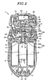
- Fig. 2 illustrates a cross sectional view taken along line II-II of Fig. 1
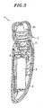
- Fig. 3 illustrates a cross sectional view taken along line III-III of Fig. 1
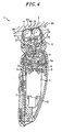
- Fig. 4 illustrates a cross sectional view taken along line IV-IV of Fig. 1
- the hair removing apparatus 1 includes a water-resistant body case 2 having a handheld configuration; and a hair removing head having a hair removing unit, the hair removing head being detachably attached at an upper portion of the water-resistant body case 2.
- the hair removing unit includes one or more rotatable cylinders 4, each having a plurality of detents on an outer peripheral surface thereof.
- each detent has a fixed detent and a movable detent which together form a pair.
- levers inserted in the rotatable cylinders 4 to pass therethrough are shifted in axial directions of the rotatable cylinders 4 by the rotation of the rotatable cylinders 4. Accordingly, the movable detent is shifted to be close to or away from the fixed detent, thus catching and pulling out the hairs.
- the hair removal mechanism and the detailed hair removal operation are described in Japanese Patent Laid-open Application No. 2001-149135 .
- the body case 2 has an envelope shape with upper portion thereof open and accommodates therein a base 7 where the motor 5 or a rechargeable battery 6 is installed.
- the base 7 has a top surface plate 7a whose peripheral portion is watertightly sealed by an O-ring 8 with respect to an inner peripheral surface of the body case 2.
- a water-resistant member 9 having an M-shaped cross section is fitted to an output terminal of the motor 5, so that an output shaft 5a projects from the water-resistant member 9 toward the hair removing head 3 through a shaft aperture 7b formed on the top surface plate 7a.
- the body case 2 has the water-resistant structure.
- the hair removing head 3 has a base unit 21 whose lower portion is inserted into an opening formed at the upper portion of the body case 2 and a head unit 22 that is floatably supported by the base unit 21.
- the base unit 21 has a pair of hooks 23 at a lower end thereof, and the hair removing head 3 can be separated from the body case 2 by user's manipulation of a release button 24.
- Gears 25 to 31 forming a drive transmission are provided in the base unit 21 and the head unit 22.
- the output shaft 5a of the motor 5 is inserted into a cylindrical coupling portion 25a of the gear 25, thereby forming an input terminal of driving force.
- a gear unit 25b connected to the coupling portion 25a is engaged with a gear unit 26a of the gear 26, and a gear formed at an axial end surface of a cylindrical portion 26 connected to the gear unit 26a is engaged with the gear 27. Therefore, a rotation from the motor 5 about an axis line extending in a vertical direction of Fig. 2 is converted to a rotation about an axis line extending in a horizontal direction.
- the rotation of the gear 27 is appropriately decelerated by the gears 28, 29 and 30 and then is transmitted from a pair of the front and rear gears 31 to the rotatable cylinders 4. Accordingly, the rotatable cylinders 4 rotate in a counterclockwise direction shown in Fig. 4 .
- a lower end of the head unit 22 is formed as a convex surface which has an arc-shaped cross section centering around an axis line passing through the side surfaces of the head unit 22, whereas an upper end of the base unit 21 is formed as a concave surface which has an arc-shaped cross section centering around the axis line passing through the side surfaces of the head unit 22.
- a pivoting fulcrum 32 is provided at an intermediate portion between a pair of front and rear rotatable cylinders 4.
- the head unit 22 is floatably supported by the base unit 21 so that it can pivot about the pivoting fulcrum 32 forward and backward as shown as arrows 33 of Fig. 4 .
- a coil spring 34 for restoring the head unit 22 pivoting forward and backward to the central position is provided at the lower end of the head unit 22.
- the rotatable cylinders 4 follow irregularity of the skin surface 35, and thus, the detents always catch hairs near the skin surface 35, i.e., near the root of the hairs. Accordingly, stress caused by the hair removal can be reduced and, also, even short hairs can be removed.
- a head frame 41 is attached to the upper portion of the hair removing head 3.
- the head frame 41 includes a frame body 42 enclosing the rotatable cylinders 41; and screen wires 43 that are fitted to the frame body 42 and installed in a plurality of lines along the outer peripheral surfaces of the two rotatable cylinders 4, for maintaining a specific gap between the skin surface 35 and the rotatable cylinders 4.
- the head frame 41 further includes a comb 44 that fills the recess between the two rotatable cylinders 4 to facilitate the sliding of the head frame 41 on the skin surface 35; a bubble collecting plate 46 provided at a leading side of the head frame 41 in terms of a movement direction of the hair removing head 3, the movement direction being indicated by an arrow 45; and a wiper 47 provided at a trailing side of the head frame 41.
- both side portions 42a and 42b of the frame body 42, the bubble collecting plate 46 and the wiper 47 form the bubble retention member that retains therein bubbles and encloses the rotatable cylinders 4 having the detents serving as the hair removing unit.
- the soap bubbles are used to erect hairs and reduce the friction between the skin surface 35 and the hair removing unit formed of the rotatable cylinders 4 having the detents, thereby carrying out the hair removal safely.
- the bubble retention member hinders the bubbles from being dispersed by the hair removal operation of the hair removal unit (the rotation of the rotatable cylinders 4). Therefore, the amount of bubbles can be maintained uniformly and the hair removal unit can function stably and properly.
- the hair removing unit includes the rotatable cylinders 4 having the detents, and the bubble collecting plate 46 is disposed at the downstream side of the rotation direction of the rotating rotatable cylinders 4.
- the bubble collecting plate 46 is disposed at the downstream side of the rotation direction of the rotating rotatable cylinders 4.
- the bubble collecting plate 46 is disposed at a retreated position compared to the rotatable cylinders 4 with respect to the skin surface 35. That is, a free end surface 46b of the bubble collecting plate 46 is positioned below the uppermost parts of the rotatable cylinders 4 (more specifically, below the uppermost parts of the screen wires 43 to provide a gap between the end surface 46b of the bubble collecting plate 46 and the skin surface 35). As a result, it is possible to collect bubbles newly provided from the skin surface 35 with the movement of the hair removing head 3.
- the bubble collecting plate 46 is disposed at the retreated position compared to the rotatable cylinders 4 with respect to the skin surface 35 in order to collect bubbles newly provided from the skin surface 35.
- the end surface 46b thereof is not necessarily flat.
- the bubble collecting plate 46 is not necessarily disposed at the retreated position compared to the rotatable cylinders 4 over the entire length thereof. As shown in Fig. 5 , the end surface 46b can be made wavy so that bubbles can be collected through valleys of the wavy end surface 46b.
- one or more openings 46a are formed on the bubble collecting plate 46 and, thus, it is possible to discharge via the openings 46a the bubbles excessively provided from the skin surface 35 with the movement of the hair removing head 3. Accordingly, the hair removal function can be effectively performed by maintaining the amount of bubbles uniformly.
- the hair removing unit includes the rotatable cylinders 4 having the detents, and the wiper 47 is disposed at the upstream side of the rotation direction of the rotating rotatable cylinders 4 That is, bubbles are collected at the trailing side of the hair removing head 3 in terms of the movement direction of the hair removing head 3 since the hair removing head 3 is preferably moved in the direction of the arrow 45 so that the skin surface 35 can move in the opposite direction of the rotation direction of the rotatable cylinders 4 to facilitate hair erection.
- the wiper 47 is disposed at the position same as the rotatable cylinders 4 or at a protruded position compared to the rotatable cylinders 4 with respect to the skin surface 35. That is, the uppermost portion of the wiper 47 is positioned flush with or above the uppermost portions of the rotatable cylinders 4 (more specifically, flush with or above the uppermost parts of the screen wires 43). Therefore, the bubbles on the skin surface 35 remaining at the upstream side of the rotation direction of the rotatable cylinders 4 that have completed the hair removal operation can be wiped by the wiper 47 and used without being wasted. Further, as in the case of removing hairs with a razor, it is possible to reduce time required to clean bubbles, which is convenient to use, and also possible to check the completion of the hair removal operation.
- the wiper 47 has a roller 47a in parallel with the rotatable cylinders 4; a shaft 47b for rotatably supporting the roller 47a; a wiper base 47d for supporting both end portions of the shaft 47b by using of a pair of right and left supporting pieces 47c; and a pair of right and left springs 47e for elastically biasing the wiper base 47d in a protruded direction with respect to the frame body 42.
- the wiper base 47d has a pair of right and left guide protrusions 47f.
- the wiper base 47d i.e., the roller 47a
- the wiper base 47d is elastically biased from the frame body 42 toward the skin surface 35.
- contact surfaces 47h formed at the opposite side of the receiving surfaces 47g of the guide protrusions 47f are made to be in contact with contact surfaces 42h of the frame body 42, so that the wiper base 47d can be prevented from being separated from the frame body 42.
Abstract
Description
- The present invention relates to a hair removing apparatus for removing hairs by using soap.
- A conventional hair removing apparatus is disclosed in
Japanese Patent Laid-open Application No. 2001-149135 - In the above prior art, when the hairs are removed by using soap, soap bubbles are dispersed due to the rotation of the rotatable cylinders having the detents. Thus, the amount of the bubbles on the skin surface is not maintained uniformly, which hinders the hair removing unit from stably erecting hairs with bubbles. Also, the friction between the skin surface and the hair removing unit varies depending on bubble states (that is, contact or followability of the hair removing head to the skin surface becomes poor), thereby deteriorating the hair removal efficiency.
-
DE-A-4143514 refers to a depilatory device for removing hair from the skin of a user. The device includes a depilating head, plucker elements and a trimmer. Furthermore, the device is provided with a drum, two plates and a rotating drum. -
US 5,196,021 relates to a depilatory device, namely to a device for removing body hair. It includes a housing to permit convenient gripping by a user and is formed with a rectangular opening at one end exposing a hair-plucker body which is driven by an electric motor. The hair-plucker body is in the form of a stack of disc-like elements rotated by an electric motor. - In view of the above, the present invention provides a hair removing apparatus allowing a hair removing unit to stably exhibit its function by maintaining the amount of bubbles uniformly when removing hairs by using soap.
- In accordance with the present invention, there is provided a hair removing apparatus for removing hairs by using soap including:
- a body case having a driving source therein; and
- a hair removing head attached to the body case, the hair removing head having a hair removing unit driven by the driving source to pull out the hairs, wherein the hair removing head has a bubble retention member that encloses the hair removing unit to retain soap bubbles therein. The hair removing unit includes one or more rotatable cylinders having detents, and the bubble retention member includes a bubble collecting plate disposed at a retreated position compared to the rotatable cylinders with respect to a skin surface at a downstream side of a rotation direction of the rotatable cylinders. The body case is water-resistant and the bubble collecting plate has openings.
- In accordance with the above configuration, the water-resistant body case having a handheld configuration has the driving source therein, and the hair removing head having the hair removing unit that is driven by the driving source to remove hairs is attached to the water-resistant body case. When removing the hairs, soap is used. With soap bubbles, it is possible to erect the hairs and reduce the friction between a skin surface and the hair removing unit including the rotatable cylinders having the detents. As a consequence, the hair removal can be carried out safely. In this hair removing apparatus, the hair removing head has the bubble retention member which serves as walls enclosing the hair removing unit so that the bubbles can be collected.
- Due to the presence of the bubble retention member, the bubbles are prevented from being dispersed by the hair removal operation of the hair removing unit, such as the rotation of the rotatable cylinders having the detents or the like. Therefore, the hair removing unit can function stably by maintaining the amount of bubbles uniformly.
- The hair removing unit includes one or more rotatable cylinders having detents, and the bubble retention member includes a bubble collecting plate disposed at a retreated position compared to the rotatable cylinders with respect to a skin surface at a downstream side of a rotation direction of the rotatable cylinders.
- In accordance with the above configuration, the hair removing unit includes the rotatable cylinders having the detents, and the bubbles ejected from the rotating rotatable cylinders are collected at the downstream side of the rotation direction of the rotatable cylinders. As a consequence, the bubble collecting plate is disposed at the downstream side thereof.
- Accordingly, the bubbles can be effectively collected. Besides, the bubble collecting plate is disposed at the retreated position compared to the rotatable cylinders with respect to the skin surface. As a result, it is possible to collect bubbles newly provided from the skin surface with the movement of the hair removing head.
- In accordance with the above configuration, it is possible to discharge via the openings the bubbles excessively provided from the skin surface with the movement of the hair removing head.
- Therefore, the hair removal function can be ensured by maintaining the amount of bubbles uniformly.
- Preferably, the hair removing unit includes one or more rotatable cylinders having detents, and the bubble retention member includes a wiper disposed at the position same as the rotatable cylinders or at a protruded position compared to the rotatable cylinders with respect to a skin surface at an upstream side of the rotation direction of the rotatable cylinders.
- In accordance with the above configuration, the hair removing unit includes the rotatable cylinders having the detents, and the bubbles remaining at the upstream side of the rotation direction of the rotatable cylinders are wiped by the wiper. The wiper is disposed at the position same as the rotatable cylinders or at a protruded position compared to the rotatable cylinders with respect to the skin surface.
- Thus, the bubbles can be used without being wasted. Further, as in the case of removing hairs with a razor, it is possible to reduce time required to clean bubbles, which is convenient to use, and also possible to check the completion of the hair removal operation.
- Preferably, the wiper has a roller disposed in parallel with the rotatable cylinders and a link mechanism for biasing the roller toward the skin surface.
- In accordance with the above configuration, the close contact between the wiper and the skin surface can be made and, hence, the bubbles can be collected more effectively.
- The objects and features of the present invention will become apparent from the following description of embodiments, given in conjunction with the accompanying drawings, in which:
-
Fig. 1 illustrates a perspective view of an exterior structure of a hair removing apparatus in accordance with an embodiment of the present invention; -
Fig. 2 illustrates a cross sectional view taken along line II-II ofFig. 1 ; -
Fig. 3 illustrates a cross sectional view taken along line III-III ofFig. 1 ; -
Fig. 4 illustrates a cross sectional view taken along line IV-IV ofFig. 1 ; -
Fig. 5 illustrates a perspective view of a head frame; -
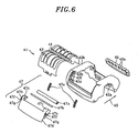
Fig. 6 illustrates a detailed exploded perspective view of a wiper in the head frame; and -
Figs. 7A and 7B respectively illustrates a cross sectional view for explaining an operation of the wiper. - Embodiments of the present invention will now be described with reference to the accompanying drawings which form a part hereof.
-
Fig. 1 illustrates a perspective view of an exterior structure of ahair removing apparatus 1 in accordance with an embodiment of the present invention;Fig. 2 illustrates a cross sectional view taken along line II-II ofFig. 1 ;Fig. 3 illustrates a cross sectional view taken along line III-III ofFig. 1 ; andFig. 4 illustrates a cross sectional view taken along line IV-IV ofFig. 1 . Thehair removing apparatus 1 includes a water-resistant body case 2 having a handheld configuration; and a hair removing head having a hair removing unit, the hair removing head being detachably attached at an upper portion of the water-resistant body case 2. - The hair removing unit includes one or more
rotatable cylinders 4, each having a plurality of detents on an outer peripheral surface thereof. When amotor 5 accommodated in thebody case 2 and serving as a driving source is driven to rotate therotatable cylinders 4, the detents catch hairs and pull out the hairs from a skin surface. To be specific, each detent has a fixed detent and a movable detent which together form a pair. Further, levers inserted in therotatable cylinders 4 to pass therethrough are shifted in axial directions of therotatable cylinders 4 by the rotation of therotatable cylinders 4. Accordingly, the movable detent is shifted to be close to or away from the fixed detent, thus catching and pulling out the hairs. The hair removal mechanism and the detailed hair removal operation are described inJapanese Patent Laid-open Application No. 2001-149135 - The
body case 2 has an envelope shape with upper portion thereof open and accommodates therein abase 7 where themotor 5 or arechargeable battery 6 is installed. Thebase 7 has atop surface plate 7a whose peripheral portion is watertightly sealed by an O-ring 8 with respect to an inner peripheral surface of thebody case 2. Moreover, a water-resistant member 9 having an M-shaped cross section is fitted to an output terminal of themotor 5, so that anoutput shaft 5a projects from the water-resistant member 9 toward thehair removing head 3 through ashaft aperture 7b formed on thetop surface plate 7a. Further, aplug base 11 on which plugterminal pins 10 are vertically installed is attached to a lower portion of thebase 7, and a peripheral portion of eachplug terminal pin 10 is watertightly sealed by an O-ring 12 at the lower portion of thebody case 2. Therefore, thebody case 2 has the water-resistant structure. - The
hair removing head 3 has abase unit 21 whose lower portion is inserted into an opening formed at the upper portion of thebody case 2 and ahead unit 22 that is floatably supported by thebase unit 21. Thebase unit 21 has a pair ofhooks 23 at a lower end thereof, and thehair removing head 3 can be separated from thebody case 2 by user's manipulation of arelease button 24. -
Gears 25 to 31 forming a drive transmission are provided in thebase unit 21 and thehead unit 22. When thehair removing head 3 is attached to thebody case 2, theoutput shaft 5a of themotor 5 is inserted into acylindrical coupling portion 25a of thegear 25, thereby forming an input terminal of driving force. Agear unit 25b connected to thecoupling portion 25a is engaged with agear unit 26a of thegear 26, and a gear formed at an axial end surface of acylindrical portion 26 connected to thegear unit 26a is engaged with thegear 27. Therefore, a rotation from themotor 5 about an axis line extending in a vertical direction ofFig. 2 is converted to a rotation about an axis line extending in a horizontal direction. The rotation of thegear 27 is appropriately decelerated by thegears rear gears 31 to therotatable cylinders 4. Accordingly, therotatable cylinders 4 rotate in a counterclockwise direction shown inFig. 4 . - As illustrated in
Fig. 4 , a lower end of thehead unit 22 is formed as a convex surface which has an arc-shaped cross section centering around an axis line passing through the side surfaces of thehead unit 22, whereas an upper end of thebase unit 21 is formed as a concave surface which has an arc-shaped cross section centering around the axis line passing through the side surfaces of thehead unit 22. Further, a pivotingfulcrum 32 is provided at an intermediate portion between a pair of front and rearrotatable cylinders 4. Thehead unit 22 is floatably supported by thebase unit 21 so that it can pivot about the pivotingfulcrum 32 forward and backward as shown asarrows 33 ofFig. 4 . Further, acoil spring 34 for restoring thehead unit 22 pivoting forward and backward to the central position is provided at the lower end of thehead unit 22. - By the pivoting of the
head unit 22, when thehead unit 22 is pressed onto askin surface 35 of a user while rotating therotatable cylinders 4, therotatable cylinders 4 follow irregularity of theskin surface 35, and thus, the detents always catch hairs near theskin surface 35, i.e., near the root of the hairs. Accordingly, stress caused by the hair removal can be reduced and, also, even short hairs can be removed. - As shown in
Figs. 5 and6 , ahead frame 41 is attached to the upper portion of thehair removing head 3. Thehead frame 41 includes aframe body 42 enclosing therotatable cylinders 41; andscreen wires 43 that are fitted to theframe body 42 and installed in a plurality of lines along the outer peripheral surfaces of the tworotatable cylinders 4, for maintaining a specific gap between theskin surface 35 and therotatable cylinders 4. Thehead frame 41 further includes acomb 44 that fills the recess between the tworotatable cylinders 4 to facilitate the sliding of thehead frame 41 on theskin surface 35; abubble collecting plate 46 provided at a leading side of thehead frame 41 in terms of a movement direction of thehair removing head 3, the movement direction being indicated by anarrow 45; and awiper 47 provided at a trailing side of thehead frame 41. - In this embodiment, it should be noted that both
side portions frame body 42, thebubble collecting plate 46 and thewiper 47 form the bubble retention member that retains therein bubbles and encloses therotatable cylinders 4 having the detents serving as the hair removing unit. - When the hairs are removed by using soap, the soap bubbles are used to erect hairs and reduce the friction between the
skin surface 35 and the hair removing unit formed of therotatable cylinders 4 having the detents, thereby carrying out the hair removal safely. At this time, the bubble retention member hinders the bubbles from being dispersed by the hair removal operation of the hair removal unit (the rotation of the rotatable cylinders 4). Therefore, the amount of bubbles can be maintained uniformly and the hair removal unit can function stably and properly. - As described above, the hair removing unit includes the
rotatable cylinders 4 having the detents, and thebubble collecting plate 46 is disposed at the downstream side of the rotation direction of the rotatingrotatable cylinders 4. The reason is that the bubbles ejected from therotatable cylinders 4 are collected at the downstream side of the rotation direction of the rotatingrotatable cylinders 4. That is, bubbles are collected at the leading side of thehair removing head 3 in terms of the movement direction of thehair removing head 3 since thehair removing head 3 is preferably moved in the direction of thearrow 45 so that theskin surface 35 can move in the opposite direction of the rotation direction of therotatable cylinders 4 to facilitate hair erection. In this embodiment, thebubble collecting plate 46 is disposed at the leading side of thehair removing head 3, so that the bubbles can be effectively collected. - Besides, the
bubble collecting plate 46 is disposed at a retreated position compared to therotatable cylinders 4 with respect to theskin surface 35. That is, afree end surface 46b of thebubble collecting plate 46 is positioned below the uppermost parts of the rotatable cylinders 4 (more specifically, below the uppermost parts of thescreen wires 43 to provide a gap between theend surface 46b of thebubble collecting plate 46 and the skin surface 35). As a result, it is possible to collect bubbles newly provided from theskin surface 35 with the movement of thehair removing head 3. - As set forth above, the
bubble collecting plate 46 is disposed at the retreated position compared to therotatable cylinders 4 with respect to theskin surface 35 in order to collect bubbles newly provided from theskin surface 35. However, theend surface 46b thereof is not necessarily flat. Moreover, thebubble collecting plate 46 is not necessarily disposed at the retreated position compared to therotatable cylinders 4 over the entire length thereof. As shown inFig. 5 , theend surface 46b can be made wavy so that bubbles can be collected through valleys of thewavy end surface 46b. - In this embodiment, one or
more openings 46a are formed on thebubble collecting plate 46 and, thus, it is possible to discharge via theopenings 46a the bubbles excessively provided from theskin surface 35 with the movement of thehair removing head 3. Accordingly, the hair removal function can be effectively performed by maintaining the amount of bubbles uniformly. - Moreover, in this embodiment, the hair removing unit includes the
rotatable cylinders 4 having the detents, and thewiper 47 is disposed at the upstream side of the rotation direction of the rotatingrotatable cylinders 4 That is, bubbles are collected at the trailing side of thehair removing head 3 in terms of the movement direction of thehair removing head 3 since thehair removing head 3 is preferably moved in the direction of thearrow 45 so that theskin surface 35 can move in the opposite direction of the rotation direction of therotatable cylinders 4 to facilitate hair erection. - Besides, the
wiper 47 is disposed at the position same as therotatable cylinders 4 or at a protruded position compared to therotatable cylinders 4 with respect to theskin surface 35. That is, the uppermost portion of thewiper 47 is positioned flush with or above the uppermost portions of the rotatable cylinders 4 (more specifically, flush with or above the uppermost parts of the screen wires 43). Therefore, the bubbles on theskin surface 35 remaining at the upstream side of the rotation direction of therotatable cylinders 4 that have completed the hair removal operation can be wiped by thewiper 47 and used without being wasted. Further, as in the case of removing hairs with a razor, it is possible to reduce time required to clean bubbles, which is convenient to use, and also possible to check the completion of the hair removal operation. - As shown in
Fig. 6 , in this embodiment, thewiper 47 has aroller 47a in parallel with therotatable cylinders 4; ashaft 47b for rotatably supporting theroller 47a; awiper base 47d for supporting both end portions of theshaft 47b by using of a pair of right and left supportingpieces 47c; and a pair of right and leftsprings 47e for elastically biasing thewiper base 47d in a protruded direction with respect to theframe body 42. Thewiper base 47d has a pair of right andleft guide protrusions 47f. When theguide protrusions 47f are inserted intoguide grooves 42f formed on theframe body 42, thewiper base 47d, i.e., theroller 47a, can move back and forth between theframe body 42 and theskin surface 35. Further, when thesprings 47e are inserted between receivingsurfaces 47g of theguide protrusions 47f and receivingsurfaces 42g of theguide grooves 42f, thewiper base 47d, i.e., theroller 47a, is elastically biased from theframe body 42 toward theskin surface 35. At this time, contact surfaces 47h formed at the opposite side of the receivingsurfaces 47g of theguide protrusions 47f are made to be in contact withcontact surfaces 42h of theframe body 42, so that thewiper base 47d can be prevented from being separated from theframe body 42. - With the above configuration, when the
head frame 41 is not in contact with theskin surface 35, theroller 47a is protruded from theframe body 42 toward theskin surface 35 by the elastic force of thesprings 47e, as shown inFig. 7A . On the contrary, when the head from 41 is in a close contact with theskin surface 35, theroller 47a is retreated into theframe body 42 against the elastic force of thesprings 47e, as illustrated inFig. 7B . As a result, close contact between theroller 47a and theskin surface 35 can be made, which makes it possible to collect bubbles more effectively. - While the invention has been shown and described with respect to the embodiments, it will be understood by those skilled in the art that various changes and modification may be made without departing from the scope of the invention as defined in the following claims.
Claims (3)
- A hair removing apparatus for removing hairs by using soap comprising:a body case (2) having a driving source (5) therein; anda hair removing head (3) attached to the body case (2), the hair removing head (3) having a hair removing unit (4) driven by the driving source (5) to pull out the hairs, whereinthe hair removing head (3) has a bubble retention member (46; 47) that encloses the hair removing unit (4) to retain soap bubbles therein, the hair removing unit (4) includes one or more rotatable cylinders (4) having detents, and the bubble retention member (46; 47) includes a bubble collecting plate (46) disposed at a retreated position compared to the rotatable cylinders (4) with respect to a skin surface at a downstream side of a rotation direction of the rotatable cylinders (4),
characterized in thatthe body case (2) is water-resistant, andthe bubble collecting plate (46) has openings (46a). - The hair removing apparatus of claim 1, wherein the bubble retention member (46; 47) further includes a wiper (47) disposed at the position same as the rotatable cylinders (4) or at a protruded position compared to the rotatable cylinders (4) with respect to a skin surface at an upstream side of the rotation direction of the rotatable cylinders (4).
- The hair removing apparatus of claim 2, wherein the wiper (47) has a roller (47a) disposed in parallel with the rotatable cylinders (4) and a link mechanism (47b; 47c; 47d; 47e; 47f; 47g; 47h) for biasing the roller (47a) toward the skin surface.
Applications Claiming Priority (1)
| Application Number | Priority Date | Filing Date | Title |
|---|---|---|---|
| JP2006315477A JP4232816B2 (en) | 2006-11-22 | 2006-11-22 | Hair removal equipment |
Publications (2)
| Publication Number | Publication Date |
|---|---|
| EP1925229A1 EP1925229A1 (en) | 2008-05-28 |
| EP1925229B1 true EP1925229B1 (en) | 2010-05-26 |
Family
ID=39156068
Family Applications (1)
| Application Number | Title | Priority Date | Filing Date |
|---|---|---|---|
| EP07022035A Not-in-force EP1925229B1 (en) | 2006-11-22 | 2007-11-13 | Hair removing apparatus |
Country Status (9)
| Country | Link |
|---|---|
| US (1) | US20080115365A1 (en) |
| EP (1) | EP1925229B1 (en) |
| JP (1) | JP4232816B2 (en) |
| KR (1) | KR100947408B1 (en) |
| CN (2) | CN201115495Y (en) |
| AT (1) | ATE468777T1 (en) |
| DE (1) | DE602007006741D1 (en) |
| ES (1) | ES2344609T3 (en) |
| RU (1) | RU2354272C1 (en) |
Families Citing this family (7)
| Publication number | Priority date | Publication date | Assignee | Title |
|---|---|---|---|---|
| JP4232816B2 (en) * | 2006-11-22 | 2009-03-04 | パナソニック電工株式会社 | Hair removal equipment |
| JP4893549B2 (en) * | 2007-09-19 | 2012-03-07 | パナソニック電工株式会社 | Hair removal equipment |
| JP4720886B2 (en) * | 2008-09-22 | 2011-07-13 | パナソニック電工株式会社 | Hair removal equipment |
| JP5002605B2 (en) * | 2009-01-15 | 2012-08-15 | パナソニック株式会社 | Electric razor |
| CN101537629B (en) * | 2009-04-23 | 2013-02-20 | 任向荣 | Shaver with changeable support |
| ES2900466T3 (en) * | 2017-10-06 | 2022-03-17 | Braun Gmbh | epilator |
| EP3569371A1 (en) * | 2018-05-16 | 2019-11-20 | Koninklijke Philips N.V. | Shaving unit with lubricating arrangement |
Family Cites Families (10)
| Publication number | Priority date | Publication date | Assignee | Title |
|---|---|---|---|---|
| JP2786910B2 (en) * | 1989-11-15 | 1998-08-13 | 松下電工株式会社 | Hair removal device |
| JP2992356B2 (en) | 1990-05-28 | 1999-12-20 | 松下電工株式会社 | Hair removal device |
| DE69233544T2 (en) * | 1991-02-20 | 2006-06-08 | Matsushita Electric Works, Ltd., Kadoma | A hair removal |
| US5196021A (en) | 1992-02-25 | 1993-03-23 | Perfect Lady Ltd. | Depilatory device |
| DE19907224C2 (en) * | 1999-02-19 | 2001-02-22 | Braun Gmbh | Liquid container |
| DE19932884C1 (en) * | 1999-07-16 | 2000-08-10 | Braun Gmbh | Depilation apparatus for plucking hair out of human skin comprises housing in which depilatory head incorporating plucking components and activated by a drive device is located |
| JP3873550B2 (en) * | 1999-11-25 | 2007-01-24 | 松下電工株式会社 | Hair removal equipment |
| CN1460002A (en) * | 2001-03-27 | 2003-12-03 | 皇家菲利浦电子有限公司 | Personal care apparatus with noise protection cap |
| US20070220755A1 (en) * | 2004-05-11 | 2007-09-27 | Gideon Dror | Shaving Apparatus |
| JP4232816B2 (en) * | 2006-11-22 | 2009-03-04 | パナソニック電工株式会社 | Hair removal equipment |
-
2006
- 2006-11-22 JP JP2006315477A patent/JP4232816B2/en not_active Expired - Fee Related
-
2007
- 2007-11-13 EP EP07022035A patent/EP1925229B1/en not_active Not-in-force
- 2007-11-13 KR KR1020070115184A patent/KR100947408B1/en not_active IP Right Cessation
- 2007-11-13 ES ES07022035T patent/ES2344609T3/en active Active
- 2007-11-13 DE DE602007006741T patent/DE602007006741D1/en active Active
- 2007-11-13 AT AT07022035T patent/ATE468777T1/en not_active IP Right Cessation
- 2007-11-14 US US11/984,129 patent/US20080115365A1/en not_active Abandoned
- 2007-11-21 RU RU2007143175/12A patent/RU2354272C1/en not_active IP Right Cessation
- 2007-11-21 CN CNU2007201932846U patent/CN201115495Y/en not_active Expired - Lifetime
- 2007-11-21 CN CN2007101886221A patent/CN101185540B/en not_active Expired - Fee Related
Also Published As
| Publication number | Publication date |
|---|---|
| CN201115495Y (en) | 2008-09-17 |
| KR20080046565A (en) | 2008-05-27 |
| JP2008125878A (en) | 2008-06-05 |
| DE602007006741D1 (en) | 2010-07-08 |
| ES2344609T3 (en) | 2010-09-01 |
| ATE468777T1 (en) | 2010-06-15 |
| JP4232816B2 (en) | 2009-03-04 |
| CN101185540A (en) | 2008-05-28 |
| US20080115365A1 (en) | 2008-05-22 |
| EP1925229A1 (en) | 2008-05-28 |
| CN101185540B (en) | 2010-06-02 |
| RU2354272C1 (en) | 2009-05-10 |
| KR100947408B1 (en) | 2010-03-12 |
Similar Documents
| Publication | Publication Date | Title |
|---|---|---|
| EP1925229B1 (en) | Hair removing apparatus | |
| KR101999552B1 (en) | Shaver with interchangeable cartridge, cartridge and head and handle assembly for such shaver | |
| EP2227359B1 (en) | Shaving device comprising a pivotably arranged assembly of cutting elements | |
| US4549352A (en) | Washable electric shaver | |
| EA022916B1 (en) | Shaving assembly (variants) | |
| US20110162207A1 (en) | Combined Hair Removal Device | |
| US4281453A (en) | Shaving apparatus | |
| JPS62172987A (en) | Dry razor | |
| US5575031A (en) | Pilly remover | |
| GB2121342A (en) | Hair cutting device | |
| JPS63194690A (en) | Electric razor | |
| JP4893549B2 (en) | Hair removal equipment | |
| JP3271938B2 (en) | Beauty equipment | |
| JP5879531B2 (en) | Electric razor | |
| JP2004236836A (en) | Rotary type electric razor | |
| JP3845997B2 (en) | Reciprocating electric razor | |
| CN219374027U (en) | Comb with cleaning function | |
| JPS6192687A (en) | Electric razor | |
| JPS583415Y2 (en) | electric razor | |
| JP2729746B2 (en) | Rotary electric razor | |
| JPH07204366A (en) | Blade mounting structure | |
| JP2811586B2 (en) | Rotary electric razor | |
| JP3992118B2 (en) | Electric razor | |
| JP3211008B2 (en) | Rotary electric razor | |
| JP6701013B2 (en) | Electric razor |
Legal Events
| Date | Code | Title | Description |
|---|---|---|---|
| PUAI | Public reference made under article 153(3) epc to a published international application that has entered the european phase |
Free format text: ORIGINAL CODE: 0009012 |
|
| AK | Designated contracting states |
Kind code of ref document: A1 Designated state(s): AT BE BG CH CY CZ DE DK EE ES FI FR GB GR HU IE IS IT LI LT LU LV MC MT NL PL PT RO SE SI SK TR |
|
| AX | Request for extension of the european patent |
Extension state: AL BA HR MK RS |
|
| 17P | Request for examination filed |
Effective date: 20081114 |
|
| AKX | Designation fees paid |
Designated state(s): AT BE BG CH CY CZ DE DK EE ES FI FR GB GR HU IE IS IT LI LT LU LV MC MT NL PL PT RO SE SI SK TR |
|
| RAP1 | Party data changed (applicant data changed or rights of an application transferred) |
Owner name: PANASONIC ELECTRIC WORKS CO., LTD. |
|
| 17Q | First examination report despatched |
Effective date: 20090219 |
|
| GRAP | Despatch of communication of intention to grant a patent |
Free format text: ORIGINAL CODE: EPIDOSNIGR1 |
|
| GRAS | Grant fee paid |
Free format text: ORIGINAL CODE: EPIDOSNIGR3 |
|
| GRAA | (expected) grant |
Free format text: ORIGINAL CODE: 0009210 |
|
| AK | Designated contracting states |
Kind code of ref document: B1 Designated state(s): AT BE BG CH CY CZ DE DK EE ES FI FR GB GR HU IE IS IT LI LT LU LV MC MT NL PL PT RO SE SI SK TR |
|
| REG | Reference to a national code |
Ref country code: GB Ref legal event code: FG4D |
|
| REG | Reference to a national code |
Ref country code: CH Ref legal event code: EP |
|
| REG | Reference to a national code |
Ref country code: IE Ref legal event code: FG4D |
|
| REF | Corresponds to: |
Ref document number: 602007006741 Country of ref document: DE Date of ref document: 20100708 Kind code of ref document: P |
|
| REG | Reference to a national code |
Ref country code: ES Ref legal event code: FG2A Ref document number: 2344609 Country of ref document: ES Kind code of ref document: T3 |
|
| REG | Reference to a national code |
Ref country code: NL Ref legal event code: VDEP Effective date: 20100526 |
|
| LTIE | Lt: invalidation of european patent or patent extension |
Effective date: 20100526 |
|
| PG25 | Lapsed in a contracting state [announced via postgrant information from national office to epo] |
Ref country code: SE Free format text: LAPSE BECAUSE OF FAILURE TO SUBMIT A TRANSLATION OF THE DESCRIPTION OR TO PAY THE FEE WITHIN THE PRESCRIBED TIME-LIMIT Effective date: 20100526 Ref country code: LT Free format text: LAPSE BECAUSE OF FAILURE TO SUBMIT A TRANSLATION OF THE DESCRIPTION OR TO PAY THE FEE WITHIN THE PRESCRIBED TIME-LIMIT Effective date: 20100526 |
|
| PG25 | Lapsed in a contracting state [announced via postgrant information from national office to epo] |
Ref country code: SI Free format text: LAPSE BECAUSE OF FAILURE TO SUBMIT A TRANSLATION OF THE DESCRIPTION OR TO PAY THE FEE WITHIN THE PRESCRIBED TIME-LIMIT Effective date: 20100526 Ref country code: AT Free format text: LAPSE BECAUSE OF FAILURE TO SUBMIT A TRANSLATION OF THE DESCRIPTION OR TO PAY THE FEE WITHIN THE PRESCRIBED TIME-LIMIT Effective date: 20100526 Ref country code: FI Free format text: LAPSE BECAUSE OF FAILURE TO SUBMIT A TRANSLATION OF THE DESCRIPTION OR TO PAY THE FEE WITHIN THE PRESCRIBED TIME-LIMIT Effective date: 20100526 Ref country code: IS Free format text: LAPSE BECAUSE OF FAILURE TO SUBMIT A TRANSLATION OF THE DESCRIPTION OR TO PAY THE FEE WITHIN THE PRESCRIBED TIME-LIMIT Effective date: 20100926 Ref country code: LV Free format text: LAPSE BECAUSE OF FAILURE TO SUBMIT A TRANSLATION OF THE DESCRIPTION OR TO PAY THE FEE WITHIN THE PRESCRIBED TIME-LIMIT Effective date: 20100526 |
|
| PG25 | Lapsed in a contracting state [announced via postgrant information from national office to epo] |
Ref country code: PL Free format text: LAPSE BECAUSE OF FAILURE TO SUBMIT A TRANSLATION OF THE DESCRIPTION OR TO PAY THE FEE WITHIN THE PRESCRIBED TIME-LIMIT Effective date: 20100526 Ref country code: CY Free format text: LAPSE BECAUSE OF FAILURE TO SUBMIT A TRANSLATION OF THE DESCRIPTION OR TO PAY THE FEE WITHIN THE PRESCRIBED TIME-LIMIT Effective date: 20100526 |
|
| PG25 | Lapsed in a contracting state [announced via postgrant information from national office to epo] |
Ref country code: GR Free format text: LAPSE BECAUSE OF FAILURE TO SUBMIT A TRANSLATION OF THE DESCRIPTION OR TO PAY THE FEE WITHIN THE PRESCRIBED TIME-LIMIT Effective date: 20100827 Ref country code: DK Free format text: LAPSE BECAUSE OF FAILURE TO SUBMIT A TRANSLATION OF THE DESCRIPTION OR TO PAY THE FEE WITHIN THE PRESCRIBED TIME-LIMIT Effective date: 20100526 Ref country code: EE Free format text: LAPSE BECAUSE OF FAILURE TO SUBMIT A TRANSLATION OF THE DESCRIPTION OR TO PAY THE FEE WITHIN THE PRESCRIBED TIME-LIMIT Effective date: 20100526 Ref country code: NL Free format text: LAPSE BECAUSE OF FAILURE TO SUBMIT A TRANSLATION OF THE DESCRIPTION OR TO PAY THE FEE WITHIN THE PRESCRIBED TIME-LIMIT Effective date: 20100526 Ref country code: PT Free format text: LAPSE BECAUSE OF FAILURE TO SUBMIT A TRANSLATION OF THE DESCRIPTION OR TO PAY THE FEE WITHIN THE PRESCRIBED TIME-LIMIT Effective date: 20100927 |
|
| PG25 | Lapsed in a contracting state [announced via postgrant information from national office to epo] |
Ref country code: SK Free format text: LAPSE BECAUSE OF FAILURE TO SUBMIT A TRANSLATION OF THE DESCRIPTION OR TO PAY THE FEE WITHIN THE PRESCRIBED TIME-LIMIT Effective date: 20100526 Ref country code: CZ Free format text: LAPSE BECAUSE OF FAILURE TO SUBMIT A TRANSLATION OF THE DESCRIPTION OR TO PAY THE FEE WITHIN THE PRESCRIBED TIME-LIMIT Effective date: 20100526 Ref country code: BE Free format text: LAPSE BECAUSE OF FAILURE TO SUBMIT A TRANSLATION OF THE DESCRIPTION OR TO PAY THE FEE WITHIN THE PRESCRIBED TIME-LIMIT Effective date: 20100526 Ref country code: RO Free format text: LAPSE BECAUSE OF FAILURE TO SUBMIT A TRANSLATION OF THE DESCRIPTION OR TO PAY THE FEE WITHIN THE PRESCRIBED TIME-LIMIT Effective date: 20100526 |
|
| PLBE | No opposition filed within time limit |
Free format text: ORIGINAL CODE: 0009261 |
|
| STAA | Information on the status of an ep patent application or granted ep patent |
Free format text: STATUS: NO OPPOSITION FILED WITHIN TIME LIMIT |
|
| 26N | No opposition filed |
Effective date: 20110301 |
|
| REG | Reference to a national code |
Ref country code: DE Ref legal event code: R097 Ref document number: 602007006741 Country of ref document: DE Effective date: 20110228 |
|
| PG25 | Lapsed in a contracting state [announced via postgrant information from national office to epo] |
Ref country code: MC Free format text: LAPSE BECAUSE OF NON-PAYMENT OF DUE FEES Effective date: 20101130 |
|
| PG25 | Lapsed in a contracting state [announced via postgrant information from national office to epo] |
Ref country code: IE Free format text: LAPSE BECAUSE OF NON-PAYMENT OF DUE FEES Effective date: 20101113 |
|
| PG25 | Lapsed in a contracting state [announced via postgrant information from national office to epo] |
Ref country code: MT Free format text: LAPSE BECAUSE OF FAILURE TO SUBMIT A TRANSLATION OF THE DESCRIPTION OR TO PAY THE FEE WITHIN THE PRESCRIBED TIME-LIMIT Effective date: 20100526 Ref country code: IT Free format text: LAPSE BECAUSE OF NON-PAYMENT OF DUE FEES Effective date: 20101113 |
|
| REG | Reference to a national code |
Ref country code: CH Ref legal event code: PL |
|
| GBPC | Gb: european patent ceased through non-payment of renewal fee |
Effective date: 20111113 |
|
| PG25 | Lapsed in a contracting state [announced via postgrant information from national office to epo] |
Ref country code: CH Free format text: LAPSE BECAUSE OF NON-PAYMENT OF DUE FEES Effective date: 20111130 Ref country code: LI Free format text: LAPSE BECAUSE OF NON-PAYMENT OF DUE FEES Effective date: 20111130 |
|
| PG25 | Lapsed in a contracting state [announced via postgrant information from national office to epo] |
Ref country code: BG Free format text: LAPSE BECAUSE OF FAILURE TO SUBMIT A TRANSLATION OF THE DESCRIPTION OR TO PAY THE FEE WITHIN THE PRESCRIBED TIME-LIMIT Effective date: 20100526 Ref country code: LU Free format text: LAPSE BECAUSE OF NON-PAYMENT OF DUE FEES Effective date: 20101113 Ref country code: HU Free format text: LAPSE BECAUSE OF FAILURE TO SUBMIT A TRANSLATION OF THE DESCRIPTION OR TO PAY THE FEE WITHIN THE PRESCRIBED TIME-LIMIT Effective date: 20101127 |
|
| PG25 | Lapsed in a contracting state [announced via postgrant information from national office to epo] |
Ref country code: GB Free format text: LAPSE BECAUSE OF NON-PAYMENT OF DUE FEES Effective date: 20111113 Ref country code: TR Free format text: LAPSE BECAUSE OF FAILURE TO SUBMIT A TRANSLATION OF THE DESCRIPTION OR TO PAY THE FEE WITHIN THE PRESCRIBED TIME-LIMIT Effective date: 20100526 |
|
| PGFP | Annual fee paid to national office [announced via postgrant information from national office to epo] |
Ref country code: FR Payment date: 20121130 Year of fee payment: 6 |
|
| PGFP | Annual fee paid to national office [announced via postgrant information from national office to epo] |
Ref country code: IT Payment date: 20121114 Year of fee payment: 6 Ref country code: ES Payment date: 20121123 Year of fee payment: 6 |
|
| PG25 | Lapsed in a contracting state [announced via postgrant information from national office to epo] |
Ref country code: BG Free format text: LAPSE BECAUSE OF FAILURE TO SUBMIT A TRANSLATION OF THE DESCRIPTION OR TO PAY THE FEE WITHIN THE PRESCRIBED TIME-LIMIT Effective date: 20100826 |
|
| PGFP | Annual fee paid to national office [announced via postgrant information from national office to epo] |
Ref country code: DE Payment date: 20131106 Year of fee payment: 7 |
|
| REG | Reference to a national code |
Ref country code: FR Ref legal event code: ST Effective date: 20140731 |
|
| PG25 | Lapsed in a contracting state [announced via postgrant information from national office to epo] |
Ref country code: IT Free format text: LAPSE BECAUSE OF NON-PAYMENT OF DUE FEES Effective date: 20131113 |
|
| PG25 | Lapsed in a contracting state [announced via postgrant information from national office to epo] |
Ref country code: FR Free format text: LAPSE BECAUSE OF NON-PAYMENT OF DUE FEES Effective date: 20131202 |
|
| REG | Reference to a national code |
Ref country code: DE Ref legal event code: R119 Ref document number: 602007006741 Country of ref document: DE |
|
| REG | Reference to a national code |
Ref country code: ES Ref legal event code: FD2A Effective date: 20150708 |
|
| PG25 | Lapsed in a contracting state [announced via postgrant information from national office to epo] |
Ref country code: ES Free format text: LAPSE BECAUSE OF NON-PAYMENT OF DUE FEES Effective date: 20131114 |
|
| PG25 | Lapsed in a contracting state [announced via postgrant information from national office to epo] |
Ref country code: DE Free format text: LAPSE BECAUSE OF NON-PAYMENT OF DUE FEES Effective date: 20150602 |