JP2004236836A - Rotary type electric razor - Google Patents

Rotary type electric razor Download PDF

Info

Publication number
JP2004236836A
JP2004236836A JP2003028892A JP2003028892A JP2004236836A JP 2004236836 A JP2004236836 A JP 2004236836A JP 2003028892 A JP2003028892 A JP 2003028892A JP 2003028892 A JP2003028892 A JP 2003028892A JP 2004236836 A JP2004236836 A JP 2004236836A
Authority
JP
Japan
Prior art keywords
blade
spring
spring unit
outer blade
center
Prior art date
Legal status (The legal status is an assumption and is not a legal conclusion. Google has not performed a legal analysis and makes no representation as to the accuracy of the status listed.)
Granted
Application number
JP2003028892A
Other languages
Japanese (ja)
Other versions
JP4010549B2 (en
Inventor
Yasuo Yamashita
康雄 山下
Yoshinori Yasufuji
義典 泰藤
Yusuke Okamoto
祐介 岡本
Kensaku Kikougawa
健作 規工川
Current Assignee (The listed assignees may be inaccurate. Google has not performed a legal analysis and makes no representation or warranty as to the accuracy of the list.)
Kyushu Hitachi Maxell Ltd
Maxell Ltd
Original Assignee
Kyushu Hitachi Maxell Ltd
Hitachi Maxell Ltd
Priority date (The priority date is an assumption and is not a legal conclusion. Google has not performed a legal analysis and makes no representation as to the accuracy of the date listed.)
Filing date
Publication date
Application filed by Kyushu Hitachi Maxell Ltd, Hitachi Maxell Ltd filed Critical Kyushu Hitachi Maxell Ltd
Priority to JP2003028892A priority Critical patent/JP4010549B2/en
Publication of JP2004236836A publication Critical patent/JP2004236836A/en
Application granted granted Critical
Publication of JP4010549B2 publication Critical patent/JP4010549B2/en
Anticipated expiration legal-status Critical
Expired - Fee Related legal-status Critical Current

Links

Images

Landscapes

  • Dry Shavers And Clippers (AREA)

Abstract

<P>PROBLEM TO BE SOLVED: To provide a rotary type electric razor eliminating an excessive external force acting on an outer blade due to an abrupt increase in shaving load, capable of always bring the outer blade into close contact with an inner blade, and capable of eliminating the deterioration in the shaving performance and the damage to the outer blade associated with a load fluctuation. <P>SOLUTION: The outer blade 16 is assembled with net blade bodies 98 and outer blade holding frames 99 securing the front and rear ends of the net blade body 98 and retaining its shape in inverted U-shape to a cassette. A front spring unit 113, a center spring unit 114, and a rear spring unit 115 are arranged at a front or rear position of the inner surface of and the front and rear center positions of an outer blade holder 12, respectively. The front and rear ends of respective outer blade holding frames 99 are moved and biased in a direction in which the net blade bodies 98 come into close contact with the inner blades 15 by the front spring unit 113 and the center spring unit 114, and by the center spring unit 114 and the rear spring unit 115, respectively, respective spring units 113,114,115 dampen and absorb the posture change and tension change of the outer blade 16 due to the load fluctuation, thereby the excessive outer force is prevented from acting on the outer blades 16. <P>COPYRIGHT: (C)2004,JPO&NCIPI

Description

【0001】
【発明の属する技術分野】
本発明は、前後一対のロータリー内刃と、これに接する外刃とを備えている電気かみそりに関し、外刃の緊張構造を改良したものである。
【0002】
【従来の技術】
ロータリー式電気かみそりにおける外刃の緊張構造に関して、前後に隣接する外刃を前端ピース、中央ピース、後端ピースの三者で緊張することは公知である(特許文献1参照)。そこでは中央ピースおよび後端ピースに、前後の外刃の後縁を固定し、前端ピースおよび中央ピースに設けた弾性腕に、前後の外刃の前縁を固定して、切断負荷の急増によって外刃が内刃の回転方向下手側(以下、単に回転下手側という)へ引き摺られて弛むのを防止し、以て負荷変動時の切れ味の低下を防止している。
【0003】
【特許文献1】
特開平9−38353号公報(段落番号0016、図19、図20)
【0004】
【発明が解決しようとする課題】
特許文献1における外刃は、外刃の回転上手側の端縁を固定し、回転下手側の端縁のみを弾性腕で引っ張って、外刃を回転下手側にのみ引っ張り付勢する緊張構造になっている。そのため、切断負荷が急激に増加し、外刃に過剰な外力が作用するような場合に、一瞬とは言えその切断刃面が内刃の歯面から浮き離れ、切れ味が損なわれることがある。最悪の場合には、過大な負荷が作用するとき、外刃の一部が破損するおそれがある。外刃を片側にのみ引っ張り付勢するので、充分な応答速度が得られにくい。プラスチック成形された弾性腕が自由状態へ復帰する際の弾性力で外刃を一方向へ引き寄せるので、弛みの吸収ストロークが小さいうえ、緊張力(弾性力)が急速に減少するのを避けられず、そのことも応答度が遅い一因になっている。
【0005】
一対の内刃は小さな間隔を介して前後に隣接しているが、この隙間の真下に中央ピースを配置するので、中央ピースが邪魔になってセンター刃を駆動するための動力伝動系を配置する余地がなく、従って前後一対の内刃の間にセンター刃を配置した電気かみそりを構成できず、電気かみそりをシリーズ商品化するうえで制約がある。
【0006】
本発明の目的は、外刃の前後縁のそれぞれを独立した緊張具によって引っ張り付勢することにより、負荷変動に追随して外刃を上下動ないし前後傾動させて、過剰な外力が外刃に作用するのを吸収緩和できる、ロータリー式電気かみそりを提供することにある。本発明の目的は、外刃に過剰な切断負荷が作用するのを解消しながら、外刃を内刃に対して常に密着できるようにし、以て負荷変動に伴う切れ味の低下を解消することにある。本発明の目的は、前後一対の内刃の間に往復動刃を設けることができ、従って、機能が異なる電気かみそりを多種類用意してシリーズ商品化することができるようにすることにある。
【0007】
【課題を解決するための手段】
本発明の電気かみそりにおいては、カセット化した外刃16の前後を、前ばねユニット113と中央ばねユニット114、および中央ばねユニット114と後ばねユニット115で押し下げ付勢して、外刃16をこれが負荷変動に追随して上下動ないし前後傾動できるように支持する。
【0008】
具体的には、図1に示すように、かみそりヘッド2の前後に、回転自在に軸支される内刃15と、内刃15に外接する外刃16とがそれぞれ配置してあるロータリー式の電気かみそりにおいて、外刃16は、シート状の網刃体98と、網刃体98の前後縁を固定して、網刃体98を逆U字状に保形する外刃保持枠99とを含んでカセット化されている。外刃ホルダー12の内面前後と前後中央のそれぞれに、外刃保持枠99を介して網刃体98を内刃15に密着付勢する前ばねユニット113、中央ばねユニット114、後ばねユニット115を配置する。前後に隣接する一対の外刃保持枠99の前後縁は、それぞれ前ばねユニット113と中央ばねユニット114、および中央ばねユニット114と後ばねユニット115で、網刃体98をこれが内刃15に密着する向きに移動付勢することを特徴とする。
【0009】
前ばねユニット113および後ばねユニット115は、外刃ホルダー12で上下動のみ自在に案内支持される付勢枠117と、付勢枠117を押し下げ付勢するばね体118とを含み、付勢枠117と外刃保持枠99とは、外刃保持枠99を下降移動する向きにのみ相対移動できる状態で連結されている。中央ばねユニット114は、外刃ホルダー12で上下動のみ自在に案内支持される左右一対の付勢ピース132と、付勢ピース132を押し下げ付勢するばね体133とを含み、付勢ピース132と外刃保持枠99とが、外刃保持枠99を下降移動する向きにのみ相対移動できる状態で連結されている。
【0010】
図15および図16に示すように、前後の内刃15の間にはセンター刃17を配置する。外刃ホルダー12の内面左右には、中央ばねユニット114を上下動のみ自在に案内支持するばね受アーム91が、左右間隔Wを介して左右対向状に突設されており、左右のばね受アーム91が、ばね受アーム91の前後面に固定した金属製の補強板139で橋絡されており、振動子48の駆動軸68が、補強板139で囲まれた前記左右間隔Wを縦通する状態で配置されて、センター刃17の連結片53に係合している。
【0011】
前ばねユニット113、および後ばねユニット115のばね体118は金属製のプレス成形品で形成する。図12において、そのばね体118は、付勢枠117の片面に接合されて付勢枠117を補強する補強壁124と、補強壁124の上縁に折り曲げ形成された左右一対のばね腕125とを一体に備えている。中央ばねユニット115のばね体133は、図1に示すように、付勢ピース132とばね受アーム91との間に配置した圧縮コイル形のばねからなる。
【0012】
図9および図10において外刃ホルダー12は、外ケース12aと、外刃16およびセンター刃17が組み付けられる内ケース12bとで構成されており、内ケース12bと外ケース12aとが、分離可能に係合連結されており、前後の外刃16とセンター刃17とが、内ケース12bに対して個別に分離可能に係合装着されている。
【0013】
【発明の作用効果】
本発明に係る電気かみそりによれば、外刃16は、シート状の網刃体98と、網刃体98を逆U字状に保形する外刃保持枠99などでカセット状に構成した。つまり、網刃体98の前後縁を外刃保持枠99に固定して、網刃体98の前後端縁が遊動するのを規制した。そのうえで、外刃ホルダー12の内面前後と前後中央とのそれぞれに前ばねユニット113、中央ばねユニット114、後ばねユニット115を設けて、前後の外刃16の前後縁を、前ばねユニット113と中央ばねユニット114、および中央ばねユニット114と後ばねユニット115で緊張付勢して、外刃16の全体が上下動し、あるいは前後傾動することにより、急激な負荷の変動などによって、過剰な外力が外刃に作用するのを吸収緩和することにより、網刃体98を内刃15に常に密着付勢できるようにした。
【0014】
従って、本発明によれば、網刃体98に過剰な外力が作用するのを一掃して、シャープな切れ味を維持できるうえ、過大な負荷により網刃体98一部が破損するのを解消できる。外刃16前後縁は、各ばねユニット113・114・115で両側から引っ張り付勢するので、外刃16の姿勢や張力の変化に対応して、各ばねユニット113・114・115が弾性力を速やかに発揮し応答度を向上できる。外刃16をカセット化してあるので、その組み付け作業や交換作業を簡便に行える(請求項1)。
【0015】
付勢枠117とばね体118とで前後のばねユニット113・115が構成され、付勢ピース132とばね体133とで中央ばねユニット114が構成されていると、各ばね体118・133の張力、弾性の変化率、あるいはばねストロークなどのばね特性を必要に応じて自由に設定できるので、切断負荷の変動幅が大きい場合にも、網刃体98を切断負荷の変動に確実に追随変位させながら内刃15に密着し続けることができ、従来の外刃緊張構造に比べてひげ切断を軽快に、しかも確実に行える。
【0016】
中央ばねユニット115が、左右一対の付勢ピース132およびばね体133で構成されていると、外刃16が左右に傾動するとき、左右の付勢ピース132が個別に上下動して外刃16の傾動を吸収するので、網刃体98に内刃15に対する密着度が向上して切れ味を向上できる。付勢枠117と外刃保持枠99、および付勢ピース132と外刃保持枠99のそれぞれが、外刃保持枠99を下降移動する向きにのみ相対移動できる状態で連結したのは、網刃体98が弛み方向へ引っ張られるのを阻止しながら、外刃保持枠99の付勢枠117および付勢ピース132に対する組み付け作業を容易化することと、外刃16の間に落ち込んだ毛屑を、連結部分に設けられる長穴105・106を介して外刃ホルダー12の内部空間へ落下させて、毛屑が前後の外刃16の間に詰まるのを防ぐためである。外刃ホルダー12を水洗いするときは、流水が先の長穴105・106を内外に流下して、長穴105・106および穴周辺に付着している毛屑を洗い流すことができる利点もある(請求項2)。
【0017】
外刃ホルダー12の内面左右に設けたばね受アーム91どうしが、その前後面に固定した金属製の補強板139で橋絡されていると、片持ち梁状に突設したばね受アーム91の構造強度を向上できるので、ばね受アーム91に組み付けられる付勢ピース132や、ばね受アーム91でスライド案内される板ばね110を安定的に支持して、付勢ピース132および可動内刃52の動作が円滑化する。
【0018】
両ばね受アーム91間の左右間隔Wを利用して、振動子48の駆動軸68をセンター刃17の連結片53に係合して、センター刃17を往復駆動できるので、前後の内刃15間に中央ばねユニット114が設けてあるにもかかわらず、センター刃17を備えた電気かみそりを問題なく構成できる。従って、センター刃17の有無など、機能が異なる電気かみそりを多種類用意してシリーズ商品化し、ユーザーの購買意欲を喚起することができる。センター刃17に過剰な負荷が作用すると、振動子48の駆動軸68が前後に振れようとするが、その前後面を補強板139で支持して駆動軸68が前後に振れるのを規制でき、従ってセンター刃17を常に適正に駆動できる(請求項3)。
【0019】
前後のばねユニット113・115のばね体118が、補強壁124と左右一対のばね腕125とを一体に備えた金属製のプレス成形品で形成されていると、補強壁124で付勢枠117を補強して、付勢枠117を可能な限り薄く形成できる。従って、前後のばねユニット113・115を組み付けるのに必要な空間を小さくでき、その分だけ外刃ホルダー12をコンパクト化し、あるいは外刃ホルダー12内により多くの部品を集約配置できる。補強壁124と一対のばね腕125とを一体に形成するので、前後のばねユニット113・115の構成部品点数を削減できる利点もある(請求項4)。
【0020】
外刃16およびセンター刃17が組み付けられる内ケース12bと、外ケース12aとで外刃ホルダー12を構成し、内ケース12bを外ケース12aに対して分離可能に係合固定し、さらに前後の外刃16とセンター刃17とを、内ケース12bに対して個別に分離可能に係合装着すると、外刃16、センター刃17、内ケース12bの三者をまとめて交換できるし、あるいはセンター刃17と、前または後の外刃16をそれぞれ個別に交換することができるので、各部材の損耗状況や破損状況に応じて必要な部材のみを交換できて経済的である。
【0021】
【実施例】
図1ないし図16は本発明に係るロータリー式電気かみそりの実施例を示す。図2ないし図4において電気かみそりは、本体ケース1とその上部に設けたかみそりヘッド2と、本体ケース1に収容される電装品ユニット3などを主な構造体としている。
【0022】
本体ケース1の前面には、モーター起動用のスイッチボタン5、そのロックボタン6、および運転モードを切り換えるセレクトボタン7などを含む切り換え操作具と、表示具とを設けてある。表示具は、セレクトボタン7の上側に設けた充電灯8と、電池残量表示灯9と、ケース上部に設けられて運転モードに応じて色が変化する逆U字状のモード表示灯10と、ひげセンサーのオンオフに連動して点灯するセンサー灯11の4種を含む。符号12は外刃ホルダーである。
【0023】
図3において本体ケース1の背面側には、きわぞり刃(往復動刃)13と、きわぞり刃13を駆動位置へ押し上げ操作するスライドノブ14とを設けてある。かみそりヘッド2には、横軸まわりに回転する前後一対ずつの内刃15と、内刃15に密着する前後一対の外刃16と、一対の内刃15の間に配置されるセンター刃(往復動刃)17と、これらを駆動する駆動機構などを配置してある。かみそりヘッド2の左右には、かみそりヘッド2を前後揺動不能にロック固定するためのロックノブ18と、外刃ホルダー12をロック解除操作する左右一対の解除ボタン19などが設けてある。
【0024】
図4において電装品ユニット3は、内フレーム25と、内フレーム25の前面に装着される回路基板26と、回路基板26の背面側に配置される左右一対の2次電池27と、回路基板26に組み付けられる電源スイッチ、および各種の表示用LED等で構成してある。
【0025】
電装品ユニット3を本体ケース1内に装着した後、下面開口を塞ぐ底ケース21と内フレーム25とをビスで締結することにより、本体ケース1と、電装品ユニット3と、底ケース21の3者を分離不能に一体化できる。この組み立て状態において、電装品ユニット3を含むケース内空間は、ケースパッキン28で防水されている(図5参照)。かみそりヘッド2は、その下面に固定した浮動フレーム29を介して内フレーム25に装着され、前後左右および上下の全方位へフロート自在に支持されている。
【0026】
図2において、かみそりヘッド2には、モーター31と、遊星歯車機構からなる減速機構32とをユニット化した動力モジュールと、減速機構32で減速したモーター動力を内刃15に伝える巻掛伝動機構33と、モーター動力を左右方向の往復動力に変換してきわぞり刃13、およびセンター刃17に伝える動力系などが設けてある。
【0027】
図5において巻掛伝動機構32は、減速機構の出力軸34に固定される原動プーリー35と、終段軸36に固定される従動プーリー37と、両プーリー35・36に巻き掛け装着されるタイミングベルト38などで構成する。終段軸36に設けた終段ギヤ39で、前後の内刃15を同時に回転駆動する。
【0028】
モーター31の回転動力を左右方向の往復動作に変換するために起振構造を設けてある。図6においてその起振構造は、動力モジュールの側面に固定されるガイド板40と、モーター31の出力軸に固定される駆動カム41と、駆動カム41で上下に往復駆動される受動ピース42と、受動ピース42の上下動作を左右動作に直接変換する逆L字状の伝動ベルト43と、伝動ベルト43の左右動作を受け継ぐスライド片44とを含む。伝動ベルト43は、ポリイミド繊維で強化されたポリウレタン製のタイミングベルトからなり、その屈曲部の内外が変向ギヤ45と遊転ローラー46とで変向案内されている。
【0029】
図6においてスライド片44に伝動された往復動力は、その上面中央に突設した駆動ピン47と振動子48とからなる往復動力伝動系を介してセンター刃17に伝動され、同時にスライド片44の後面に設けた駆動アーム49を介してきわぞり刃13に伝動される。
【0030】
図7においてかみそりヘッド2は、動力モジュールの上面に装着固定されるヘッドフレーム55と、ヘッドフレーム55で前後揺動可能に支持される揺動枠56、および内刃支持枠57と、内刃支持枠57に対して前後面からそれぞれ着脱可能に装着される内刃ユニット58と、内刃支持枠55に着脱自在に装着される外刃ホルダー12と、内刃支持枠57の内部に収容される振動子48などで構成してある。ヘッドフレーム55、揺動枠56、および内刃支持枠57はそれぞれプラスチック成形品である。
【0031】
ヘッドフレーム55は、下向きに開口するケース部60と、ケース部60の上面両側に立設した側壁61とを備えており、左右の側壁61で揺動枠56を前後揺動可能に軸支する。そのために、ケース部60の上面壁は揺動枠56の揺動軌跡に沿って下凹み円弧状に形成されている。四角枠状に形成される揺動枠56の上面左右には、上端に揺動ボス62を備えた揺動腕63が立設されており、先の側壁61で揺動ボスを前後揺動自在に軸支する。
【0032】
これにより、ヘッドフレーム55を除く、揺動枠56および内刃支持枠57などの各部材が前後方向に揺動できる。しかし、ロックノブ18を押し下げると揺動できない状態になる。片方の揺動ボス62に、終段軸36と終段ギヤ39とが組み込まれている(図6参照)。振動子48の左右両端の取付部は揺動枠56に固定してある。
【0033】
内刃支持枠57は、下向きに開口する角箱状のカバー部65と、カバー部65の上面左右に突設されるトンネル断面状のアーチ部66とを一体に備えており、揺動枠56に上面側から係合装着されてヘッドフレーム55の上面を側壁61ごとカバーする。カバー部65の上面4箇所には、内刃ユニット58を前側、あるいは後側から係合装着するための装着部67を形成してある。
【0034】
内刃支持枠57を揺動枠56に装着することにより、振動子48の駆動軸68のみがカバー部65の上面の開口から上方へ突出するが、この開口と駆動軸68との間はパッキン69で封止する(図6参照)。内刃支持枠57のアーチ部66の外側壁に、先に述べたロックノブ18と解除ボタン19とが組み込まれる。
【0035】
図7および図8において内刃ユニット58は、左右に長いH字状の内刃フレーム72と、内刃フレーム72で軸支される内刃15と、内刃15の両側端に突設される内刃軸73と、片方の内刃軸73に固定した内刃ギヤ74とからなる。内刃フレーム72の左右の脚下部には、先の装着部67と係合する係合溝75が左右対向状に設けてある。内刃15は、円柱状のプラスチック製ホルダーの周面に、一群の金属切刃をスパイラル状に埋設固定して構成する。
【0036】
内刃支持枠57に装着した内刃ユニット58を前後移動不能に係合捕捉するためのロック機構が、内刃支持枠57の内部に設けてある。図8においてロック機構は、前後に長いロックアーム77と、ロックアーム77を押し上げ付勢する圧縮コイル形のロックばね78とからなる。
【0037】
ロックアーム77の前後端には、内刃フレーム72を係合捕捉する係合爪79を上向きに突設してある。内刃ユニット58を装着部67に差し込み装着した状態においては、ロックアーム77の係合爪79が内刃フレーム72の両側部に係合する。これにより内刃ユニット58は、前後、左右、上下の全方位へ移動不能に保持固定される。
【0038】
外刃ホルダー12は、前後一対の外刃16およびセンター刃17を支持する内ケース12bと、内ケース12bを支持する外ケース12aとに分けて構成する。図9および図10に示すように、外ケース12aは門形に形成される左右一対の側枠81と、側枠81の下部どうしを繋ぐ前後の横枠82とで上下面が開口する枠体状に形成する。左右に対向する両側枠81の内面の中央上部には、内ケース12bを係合装着するための第1係合凹部83が形成されている。両側枠81の内面の下面前後には、解除ボタン19と一体形成した係合爪85(図15参照)で係合捕捉される第2係合凹部84が形成されている。
【0039】
図10および図11において内ケース12bは、外ケース12aと同様に左右一対の側枠86と、側枠86の下部どうしを繋ぐ前後の横枠87とで上下面が開口する枠体状に形成するが、全体を外ケース12aよりひと回り小さく形成する。両側枠86の外側面には、先の第1係合部83と係合する係合爪88を一体に形成してある。
【0040】
図10に示すように、両側枠86の内面上部には、固定外刃51の両側端を支持する左右一対の刃支持部89と、両刃支持部89の突端から下向きに延びる縦壁90と、両縦壁90の下端から左右対向状に突設されるばね受アーム91とを階段状に形成してある。両縦壁90の対向面に固定外刃51の取付ピース54を係合するための突起92が形成されている。
【0041】
図11に示すように、前後の横枠87の対向面と、左右のばね受アーム91の前後面のそれぞれには、外刃16を装着するためのピン94・95を突設してある。横枠87側のピン94は3個ずつ、ばね受アーム91側のピンは95はそれぞれ2個ずつ形成する。ばね受アーム91には、後述する付勢ピース132を上下スライドのみ自在に支持する下向きのガイド凹部96が形成されている。
【0042】
図12および図13に示すように、外刃16の交換を容易化するために、前後の外刃16は、シート状の網刃体98と、網刃体98を支持する外刃保持枠99とでカセット化してある。外刃保持枠99は、左右一対の側枠101と、側枠101の下部どうしを繋ぐ前後の横枠102とで上下面が開口する枠体状に形成してあり、センター刃17と隣接する側の枠面に、外刃16の湾曲姿勢を規定する刃受壁103が形成されている。
【0043】
横枠102の前後面には、網刃体98を溶着固定するためのピン104をそれぞれ4個ずつ形成してある。網刃体98を逆U字状に湾曲したうえで、その前後縁に設けた穴をピン104に係合し、ピン104を溶着することにより、網刃体98と外刃保持枠99とを一体化しカセット化できる。このように外刃16をカセット化すると、網刃体98を外刃保持枠99ごと内ケース12bから取り外して網刃体98を交換できるので、交換作業が簡便に行え、交換時に網刃体98をいためることもない。横枠102および網刃体98の前後端には、後述する緊張具を連結するための長穴105・106が形成されている。
【0044】
図14においてセンター刃17は、内ケース12bに固定される断面逆U字状の固定外刃51と、固定外刃51の内面に配置される断面逆U字状の可動内刃52とで構成してある。固定外刃51と可動内刃52の歯面には、それぞれ逆U字状のスリット刃を形成してあり、両切刃のせん断作用によって、主として長毛やくせ毛を切断する。固定外刃51の両端には取付ピース54を溶着固定してあり、可動内刃52の中央下面には連結片53を溶着固定してある。取付ピース54には、可動内刃52をスライド案内する逆U字状のガイド部108と、係合脚片109と、固定外刃51の左右両端を受け止める断面逆U字状の刃受部112とが一体に設けてある。
【0045】
可動内刃52を固定外刃51に組み付けた状態で、取付ピース54を固定外刃51に溶着固定することにより、これら3者51・52・54を分離不能に一体化して1個のユニット部品としてカセット化でき、従って、センター刃17の交換をより少ない手間で行える。
【0046】
センター刃17は、内ケース12bに対してケース上方から組み付るが、組み付け状態においては図15に示すように、係合脚片109が内ケース12bの縦壁90に設けた突起92と係合して、センター刃17を内ケース12bに対して分離不能に固定保持する。この組み付け状態において、刃受部112はその内面が刃支持部89に支持され、さらに前後壁面が刃支持部89の前後に設けた一対のガイド壁93(図11および図13参照)で上下動のみ可能に案内支持してある。連結片53には板ばね110を組み付けてあり、左右のばね腕をばね受アーム91の上面で受け止めることにより、可動内刃52の全体が固定外刃51に押し付けられた状態で、左右スライドできる。不使用状態におけるセンター刃17は、図15に示すように、全体が板ばね110で押し上げられて、係合脚片109が突起92で受け止められている。使用状態では、肌の凹凸に追従してセンター刃17が上下動することで、センター刃17による肌当たりを和らげることができる。連結片53には受動溝111が形成してあり、受動溝111が振動子48の駆動軸68と係合することにより、駆動軸49の左右往復動作を連結片53を介して可動内刃52に伝動できる。
【0047】
センター刃17による長毛やくせ毛の切断をより効果的に行うために、網刃体98にスリット100が形成されている。詳しくは、図16に示すように、網刃体98におけるシート面の殆どには、内刃15と協同してひげ切断を行う網刃を形成するが、センター刃17と対向する前後の網刃体98のシート面にスリット100を横列状に形成している(図9参照)。図16において、網刃の形成領域を符号Z1で示し、スリット100の形成領域を符号Z2で示した。
【0048】
このように、センター刃17と対向するシート面にスリット100が横列状に形成されていると、長毛やくせ毛を切断する際に、その毛先側をスリット100で捕捉して、センター刃17による長毛やくせ毛の切断が効果的に行える。なお、スリット100による長毛の捕捉をより確実に行うために、図9に示すように、スリット100の列幅B1は、固定外刃51におけるスリット刃の左右全幅B2より大きく設定してある。
【0049】
外刃16を上下動可能に支持し、かつ内刃15に密着付勢するために、外刃ホルダー12の内面前後と、前後中央の3箇所には、前ばねユニット113、中央ばねユニット114、後ばねユニット115からなる緊張具が設けられている。
【0050】
図12において前ばねユニット113は、左右に長い帯板状の付勢枠117と、付勢枠117を押し下げ付勢するばね体118とで構成する。付勢枠117はプラスチック成形品であり、その板面の前後には、ばね体118を固定するための4個のピン119と、外刃保持枠99を係合連結するための4個の係合ピン120とが設けてある。付勢枠117の板面の左右3箇所には上下方向の長穴121を形成してある。
【0051】
ばね体118は、ステンレス板材を素材とするプレス成形品からなり、付勢枠117を補強する左右に長い帯状の補強壁124と、補強壁124の上縁中央寄りから斜め上向きに折り曲げ形成される一対のばね腕125とで構成する。補強壁124の面壁には、先のピン119と係合する4個の穴126と、付勢枠117に設けた長穴121に対応する3個の長穴127とが通設してある。補強壁124を付勢枠117の片面に接合し、穴126に挿通したピン119の突端を溶融変形することにより、ばね体118と付勢枠117とを一体化して、付勢枠117を補強壁124で補強できる。
【0052】
図1に示すように、付勢枠117およびばね体118の長穴121・127を、内ケース12bの横枠87内面に突設したピン94で案内支持することにより、前ばねユニット13を内ケース12bで上下動自在に支持できる。ばね腕125の端部上面を横枠87の内面に形成した段部129で受け止めることにより、前ばねユニット13の全体が押し下げ付勢される。
【0053】
後ばねユニット115は、前ばねユニット113と同じ構造であって、前ばねユニット113を前後に反転して使用するだけであるので、同じ部材に同じ符号を付してその説明を省略する。
【0054】
図11において中央ばねユニット114は、ばね受アーム91のガイド凹部96で上下スライド自在に案内支持される左右一対の付勢ピース132と、付勢ピース132を押し下げ付勢するばね体133とで構成する。付勢ピース132は、中央にばね受部134を備えたプラスチック成形品であり、ばね受部134の左右に突設した側壁135の前後面のそれぞれに、外刃保持枠99を係合連結するための4個の係合ピン136を設けてある。ばね体133は圧縮コイル形のばねからなり、ばね受アーム91のガイド凹部96とばね受部134との間に配置されている。
【0055】
ばね受アーム91は、それぞれ片持ち梁状に形成してある。そこで、その前後面に補強板139を橋絡状に固定してばね受アーム91の構造強度を増強している。図11に示すように補強板139は、ステンレス板材を素材とする左右に長い帯状のプレス成形品からなり、板面の左右に溶着用の4個の穴140と、上下方向の4個の長穴141とを通設してある。付勢ピース132の係合ピン136を長穴141に係合したうえで、ガイド凹部96内にばね体133を装填した状態で、補強板139をばね受アーム91の前後面に接合し、補強板139の穴140に挿通したピン95の突端を溶融変形することにより、補強板139がばね受アーム91に固定され、同時に付勢ピース132をばね受アーム91に対して分離不能に支持することができる。
【0056】
図15に示すように左右のばね受アーム91は、左右間隔Wを介して対向するが、この左右間隔Wを利用して振動子48の駆動軸68を配置する。具体的には、外刃ホルダー12を内刃支持枠57に装着した状態において、駆動軸68が左右間隔Wを縦通して連結片53の受動溝111と係合し、振動子48の往復動力を可動内刃52に伝動できるように構成する。
【0057】
この組み付け状態において、連結片53および駆動軸68の前後面は、図16に示すようにそれぞれ補強板139と正対している。従って、センター刃17に過大な負荷が作用し、駆動軸68が前後にぐらつこうとするとき、その前後面を補強板139で受け止めて適正に往復動させることができる。
【0058】
上記の各ばねユニット113・114・115を内ケース12bに組み付けた状態で、外刃16を内ケース12bの下面側からケース内へはめ込み、網刃体98および外刃保持枠99の長穴105・106を、例えば前ばねユニット113の係合ピン120にはめ込む。その状態で、外刃保持枠99の後側の横枠102を弾性変形させながら、長穴105・106を付勢ピース132の係合ピン136に係合して、外刃16を内ケース12bに装着する。後側の外刃16も同様の要領で内ケース12bに装着する。
【0059】
内ケース12bを外ケース12aに対して下面側から装着することにより、その側枠86の外面に設けた係合爪88が、外ケース12aの側枠81の内面に設けた第1係合部83と係合して、両ケース12a・12bを一体化できる。このように、外刃ホルダー12が、外ケース12aと内ケース12bとで構成されていると、内ケース12bと、同ケース12bに組まれた前後の外刃16、およびセンター刃17を、ひとつのユニット部品として交換できるのはもちろんのこと、前後の外刃16と、センター刃17の三者を個別に交換することができるので、各部材の損耗状況や破損状況に応じて必要な部材のみを交換できて経済的である。また、外刃16、センター刃17、内ケース12bの三者を分解することにより、これらの清掃を簡便に行えることにもなる。
【0060】
図1に示すように、外刃ホルダー12を内刃支持枠57に装着した状態においては、各ばねユニット113・114・115のばね体118・133が弾性変形しており、これらばね体118・133の弾性力によって外刃支持枠99の前後縁のいずれもが下向きに押し下げ付勢されるので、網刃体98の湾曲部分を内刃15の外面に密着できる。このとき、係合ピン120・136は、網刃体98、および外刃支持枠99の長穴105・106の穴下端に接当している。
【0061】
つまり、付勢枠117と外刃保持枠99、および付勢ピース132と外刃保持枠99とは、それぞれ外刃保持枠99が下降移動する向きにのみ相対移動できる状態で連結されている。しかし、各ばね体118・133は既に弾性変形した状態になっているので、網刃体98の張力や姿勢等が変化するときは、これらの変化に応じてばね体118・133が上下に変位して、姿勢変動などを直ちに吸収する。一組の付勢ピース132で前後の網刃体98を同時に緊張付勢すると、前後の網刃体98を個別に緊張付勢する場合に比べて、中央ばねユニット114の構成部品点数が減り、その分だけ製造コストを削減できる。
【0062】
図17に示すように、外刃ホルダー12を内刃支持枠57から取り外した状態においては、付勢枠117および付勢ピース132のそれぞれがばね体118・133で押し下げられて、長穴121の内面上端がピン94で受け止められ、付勢ピース132に設けた係合ピン136が補強枠139に設けた長穴141の下端で受け止められている。さらに、前後の外刃16は自重で下降するため、外刃保持枠99に設けた前後の長穴105の内面上端が、付勢枠117および付勢ピース132の係合ピン120・136で受け止められている。この状態の外刃ホルダー12を内刃支持枠57に装着すると、図1に示すように、外刃16が内刃15で受け止められ、各ばね体118・133が弾性変形されて、網刃体98を内刃15に密着できる。
【0063】
図18は外刃緊張構造の別実施例を示す。図18(a)は、中央ばねユニット114が、前後一対ずつの付勢ピース132と、ばね体133とで構成され、前後の外刃支持枠99が前後の付勢ピース132で個別に緊張付勢できるようにしてあり、この点が先の実施例と異なる。このように、前後の外刃支持枠99を個別に設けられた付勢ピース132で押し下げ付勢すると、前後の外刃16の姿勢や緊張力の変動の吸収をさらに的確に行える。他は先の実施例と同じであるので、同じ部材に同じ符号を付して、その説明を省略する。以下においても同様に扱う。
【0064】
図18(b)は、3組の内刃15および外刃16が前後に隣接配置された電気かみそりを示す。そこでは中央の内刃15および外刃16と、前後の内刃15および外刃16との間に、2組の中央ばねユニット114を配置して、各外刃16の前後縁を前後のばねユニット113・115と、2組の中央ばねユニット114で緊張付勢した点が先の実施例とは異なる。この場合の中央ばねユニット114は、図1に示す構造としたが、図18(a)に示す構造であってもよい。
【0065】
上記の実施例以外に、外刃ホルダー12は1個の独立部品で構成することができ、実施例で説明したように外ケース12aと内ケース12bとで構成する必要はない。前後のばねユニット113・115のばねは、板ばねである必要はなく、圧縮コイルばねや捻りコイルばねを適用できる。必要に応じて、付勢枠117に一体形成した弾性アームで外刃16を緊張付勢してもよい。外刃保持枠99は左右一対の側枠101のうち、片方の側枠101を省略してコ字枠状に形成することができる。
【図面の簡単な説明】
【図1】外刃の緊張構造を示す概略断面図である。
【図2】電気かみそりの正面図である。
【図3】電気かみそりの側面図である。
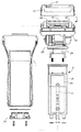
【図4】電気かみそりの分解正面図である。
【図5】かみそりヘッドの縦断正面である。
【図6】かみそりヘッドの中央縦断正面である。
【図7】かみそりヘッドの動力伝動系を省略した分解正面図である。
【図8】内刃ユニットの取付構造を示す縦断側面図である。
【図9】外刃ホルダーの分解斜視図である。
【図10】外刃ホルダーとセンター刃の関係を示す分解断面図である。
【図11】内ケースと中央ばねユニットの分解斜視図である。
【図12】外刃の分解斜視図である。
【図13】外刃の緊張構造を示す分解断面図である。
【図14】センター刃の分解斜視図である。
【図15】センター刃の駆動構造を示す縦断正面図である。
【図16】外刃とセンター刃の関係構造を示す縦断側面図である。
【図17】かみそりヘッドから取り外した外刃ホルダーの縦断側面図である。
【図18】外刃の緊張構造の別実施例を示す概略断面図である。
【符合の説明】
2 かみそりヘッド
12 外刃ホルダー
12a 外ケース
12b 内ケース
15 内刃
16 外刃
17 センター刃
48 振動子
53 連結片
68 駆動軸
91 ばね受アーム
98 網刃体
99 外刃保持枠
113 前ばねユニット
114 中央ばねユニット
115 後ばねユニット
117 付勢枠
118 ばね体
124 補強壁
125 ばね腕
132 付勢ピース
133 ばね体
139 補強板
[0001]
TECHNICAL FIELD OF THE INVENTION
The present invention relates to an electric shaver including a pair of front and rear rotary inner blades and an outer blade in contact with the rotary inner blade, and improves a tension structure of the outer blade.
[0002]
[Prior art]
With respect to the tensioning structure of the outer blades in a rotary electric shaver, it is known that front and rear adjacent outer blades are tensioned by a front end piece, a center piece and a rear end piece (see Patent Document 1). There, the rear edges of the front and rear outer blades are fixed to the center piece and the rear end piece, and the front edges of the front and rear outer blades are fixed to the elastic arms provided on the front end piece and the center piece. The outer blade is prevented from being loosened by being dragged toward the lower side in the rotation direction of the inner blade (hereinafter, simply referred to as the lower side of rotation), thereby preventing the sharpness at the time of load change from being reduced.
[0003]
[Patent Document 1]
JP-A-9-38353 (paragraph number 0016, FIGS. 19 and 20)
[0004]
[Problems to be solved by the invention]
The outer blade in Patent Document 1 has a tension structure in which the edge on the upper side of rotation of the outer blade is fixed, only the edge on the lower side of rotation is pulled by an elastic arm, and the outer blade is pulled and urged only on the lower side of rotation. Has become. Therefore, when the cutting load increases sharply and an excessive external force acts on the outer blade, the cutting blade surface may be lifted from the tooth surface of the inner blade for a moment, and the sharpness may be impaired. In the worst case, when an excessive load acts, a part of the outer blade may be damaged. Since the outer blade is urged only to one side, it is difficult to obtain a sufficient response speed. The elastic arm formed of plastics pulls the outer blade in one direction by the elastic force when returning to the free state, so the slack absorption stroke is small and the tension (elastic force) cannot be avoided rapidly. This also contributes to slow response.
[0005]
The pair of inner blades are adjacent to each other with a small gap in front and back, but since the central piece is located immediately below this gap, the central piece is in the way and the power transmission system for driving the center blade is arranged. Since there is no room, an electric razor in which a center blade is arranged between a pair of front and rear inner blades cannot be formed, and there is a restriction in commercializing the electric razor.
[0006]
An object of the present invention is to pull and urge each of the front and rear edges of the outer blade with an independent tensioning tool, so that the outer blade moves up and down or tilts back and forth according to a load change, and excessive external force is applied to the outer blade. It is an object of the present invention to provide a rotary electric shaver which can absorb and reduce the action. An object of the present invention is to make it possible to always keep the outer blade in close contact with the inner blade while eliminating the excessive cutting load from acting on the outer blade, thereby eliminating the decrease in sharpness due to load fluctuation. is there. An object of the present invention is to provide a reciprocating blade between a pair of front and rear inner blades, so that various types of electric razors having different functions can be prepared and commercialized in series.
[0007]
[Means for Solving the Problems]
In the electric razor of the present invention, the front and rear of the cassette-made outer blade 16 is pushed down and biased by the front spring unit 113 and the center spring unit 114 and the center spring unit 114 and the rear spring unit 115, and the outer blade 16 is It is supported so that it can be moved up and down or tilted back and forth following a load change.
[0008]
Specifically, as shown in FIG. 1, a rotary type in which an inner blade 15 rotatably supported and an outer blade 16 circumscribing the inner blade 15 are respectively arranged before and after the razor head 2. In the electric razor, the outer blade 16 includes a sheet-like net blade body 98 and an outer blade holding frame 99 that fixes the front and rear edges of the net blade body 98 and holds the net blade body 98 in an inverted U shape. Includes a cassette. A front spring unit 113, a center spring unit 114, and a rear spring unit 115 that urge the mesh blade body 98 against the inner blade 15 via the outer blade holding frame 99 are provided on the inner surface front and rear and the front and rear center of the outer blade holder 12. Deploy. The front and rear edges of a pair of outer blade holding frames 99 adjacent to the front and rear are a front spring unit 113 and a center spring unit 114, and a center spring unit 114 and a rear spring unit 115, respectively. In a moving direction.
[0009]
The front spring unit 113 and the rear spring unit 115 include an urging frame 117 that is guided and supported by the outer blade holder 12 so as to be movable only up and down, and a spring body 118 that pushes down and urges the urging frame 117. The outer cutter holding frame 99 is connected to the outer cutter holding frame 99 in such a manner that the outer cutter holding frame 99 can be relatively moved only in a direction in which the outer cutter holding frame 99 moves downward. The center spring unit 114 includes a pair of right and left urging pieces 132 that are guided and supported by the outer blade holder 12 so that only the vertical movement is possible, and a spring body 133 that presses and urges the urging piece 132. The outer cutter holding frame 99 is connected so as to be relatively movable only in a direction in which the outer cutter holding frame 99 is moved downward.
[0010]
As shown in FIGS. 15 and 16, a center blade 17 is disposed between the front and rear inner blades 15. On the left and right sides of the inner surface of the outer blade holder 12, spring receiving arms 91 for guiding and supporting the center spring unit 114 so as to be able to move only up and down are provided so as to be opposed to each other with a left and right interval W therebetween. 91 is bridged by a metal reinforcing plate 139 fixed to the front and rear surfaces of the spring receiving arm 91, and the drive shaft 68 of the vibrator 48 vertically passes through the left-right space W surrounded by the reinforcing plate 139. It is arranged in a state and is engaged with the connecting piece 53 of the center blade 17.
[0011]
The spring body 118 of the front spring unit 113 and the rear spring unit 115 is formed by a metal press-formed product. In FIG. 12, the spring body 118 includes a reinforcing wall 124 joined to one surface of the urging frame 117 to reinforce the urging frame 117, and a pair of left and right spring arms 125 formed by bending the upper edge of the reinforcing wall 124. Is provided integrally. As shown in FIG. 1, the spring body 133 of the central spring unit 115 is formed of a compression coil type spring disposed between the urging piece 132 and the spring receiving arm 91.
[0012]
9 and 10, the outer blade holder 12 includes an outer case 12a and an inner case 12b to which the outer blade 16 and the center blade 17 are assembled. The inner case 12b and the outer case 12a can be separated. The front and rear outer blades 16 and the center blade 17 are engaged and attached to the inner case 12b so as to be individually separable.
[0013]
Effects of the Invention
According to the electric shaver according to the present invention, the outer blade 16 is formed in a cassette shape by a sheet-like net blade body 98 and an outer blade holding frame 99 for holding the net blade body 98 in an inverted U shape. That is, the front and rear edges of the net blade body 98 are fixed to the outer blade holding frame 99, and the movement of the front and rear end edges of the net blade body 98 is restricted. Then, a front spring unit 113, a center spring unit 114, and a rear spring unit 115 are provided on the inner surface front and rear and the front and rear center of the outer blade holder 12, respectively, so that the front and rear edges of the front and rear outer blades 16 are aligned with the front spring unit 113 and the center. The spring unit 114 and the center spring unit 114 and the rear spring unit 115 are urged to tension, and the entire outer blade 16 moves up and down or tilts back and forth. By absorbing and relaxing the action on the outer blade, the mesh blade body 98 can always be urged in close contact with the inner blade 15.
[0014]
Therefore, according to the present invention, the sharpness of the net blade body 98 can be maintained by eliminating the excessive external force acting on the net blade body 98, and the breakage of a part of the net blade body 98 due to an excessive load can be eliminated. . Since the front and rear edges of the outer blade 16 are pulled and biased from both sides by the spring units 113, 114 and 115, each spring unit 113, 114 and 115 responds to the change in the posture and the tension of the outer blade 16 so that the elastic force is increased. It can be quickly exerted and the response can be improved. Since the outer blade 16 is formed into a cassette, the assembling work and the replacing work can be easily performed (claim 1).
[0015]
If the front and rear spring units 113 and 115 are constituted by the urging frame 117 and the spring body 118, and the central spring unit 114 is constituted by the urging piece 132 and the spring body 133, the tension of each of the spring bodies 118 and 133 is increased. Since the spring characteristics such as the rate of change of elasticity or the spring stroke can be freely set as required, even when the fluctuation range of the cutting load is large, the net blade body 98 is surely displaced to follow the fluctuation of the cutting load. While being kept in close contact with the inner blade 15, the whisker can be cut lightly and reliably compared to the conventional outer blade tension structure.
[0016]
When the center spring unit 115 is constituted by a pair of right and left urging pieces 132 and a spring body 133, when the outer blade 16 tilts left and right, the right and left urging pieces 132 individually move up and down to move the outer blade 16 , The degree of close contact with the inner blade 15 on the net blade body 98 is improved, and the sharpness can be improved. The reason why the urging frame 117 and the outer blade holding frame 99 and the urging piece 132 and the outer blade holding frame 99 are connected in a state where they can relatively move only in the direction in which the outer blade holding frame 99 is moved downward is the mesh blade. While preventing the body 98 from being pulled in the loosening direction, the assembling work of the outer blade holding frame 99 to the urging frame 117 and the urging piece 132 is facilitated, and the shavings dropped between the outer blades 16 are removed. This is to prevent the shavings from dropping into the inner space of the outer blade holder 12 through the elongated holes 105 and 106 provided in the connecting portion, so that the shavings are clogged between the front and rear outer blades 16. When the outer blade holder 12 is washed with water, there is also an advantage that running water can flow down the inside of the long holes 105 and 106 to remove the shavings attached to the long holes 105 and 106 and around the holes. Claim 2).
[0017]
When the spring receiving arms 91 provided on the left and right sides of the inner surface of the outer blade holder 12 are bridged by metal reinforcing plates 139 fixed to the front and rear surfaces, the structure of the spring receiving arms 91 projecting in a cantilever shape. Since the strength can be improved, the urging piece 132 assembled to the spring receiving arm 91 and the leaf spring 110 slidably guided by the spring receiving arm 91 are stably supported, and the operation of the urging piece 132 and the movable inner blade 52 is performed. Is smoothed.
[0018]
The center shaft 17 can be driven reciprocally by engaging the drive shaft 68 of the vibrator 48 with the connecting piece 53 of the center blade 17 by utilizing the left and right distance W between the two spring receiving arms 91. Although the central spring unit 114 is provided therebetween, the electric shaver having the center blade 17 can be configured without any problem. Therefore, various types of electric razors having different functions such as the presence or absence of the center blade 17 can be prepared and made into a series of products, thereby stimulating a user's willingness to purchase. When an excessive load acts on the center blade 17, the drive shaft 68 of the vibrator 48 tends to swing back and forth, but the front and rear surfaces thereof are supported by the reinforcing plate 139 and the swing of the drive shaft 68 can be regulated. Therefore, the center blade 17 can always be properly driven (claim 3).
[0019]
When the spring bodies 118 of the front and rear spring units 113 and 115 are formed of a metal press-formed product integrally including the reinforcing wall 124 and the pair of left and right spring arms 125, the urging frame 117 is formed by the reinforcing wall 124. And the biasing frame 117 can be formed as thin as possible. Therefore, the space required for assembling the front and rear spring units 113 and 115 can be reduced, and the outer blade holder 12 can be made compact accordingly, or more components can be collectively arranged in the outer blade holder 12. Since the reinforcing wall 124 and the pair of spring arms 125 are formed integrally, there is an advantage that the number of components of the front and rear spring units 113 and 115 can be reduced (claim 4).
[0020]
The outer blade holder 12 is constituted by the inner case 12b to which the outer blade 16 and the center blade 17 are assembled, and the outer case 12a. The inner case 12b is separably engaged with and fixed to the outer case 12a. When the blade 16 and the center blade 17 are individually and detachably engaged with the inner case 12b, the outer blade 16, the center blade 17, and the inner case 12b can be replaced collectively. In addition, the front and rear outer blades 16 can be individually exchanged, so that only necessary members can be exchanged according to the state of wear or damage of each member, which is economical.
[0021]
【Example】
1 to 16 show an embodiment of a rotary electric shaver according to the present invention. 2 to 4, the electric razor has a main structure including a main body case 1, a razor head 2 provided on an upper part thereof, an electric component unit 3 housed in the main body case 1, and the like.
[0022]
A switching operation tool including a switch button 5 for starting a motor, a lock button 6 thereof, a select button 7 for switching an operation mode, and the like, and a display device are provided on the front surface of the main body case 1. The display includes a charging light 8 provided above the select button 7, a battery remaining amount indicating light 9, an inverted U-shaped mode indicating light 10 provided on the upper part of the case and changing color according to an operation mode. , And four types of sensor lights 11 that are turned on in conjunction with the on / off of the beard sensor. Reference numeral 12 denotes an outer blade holder.
[0023]
In FIG. 3, on the rear side of the main body case 1, a sharp blade (reciprocating blade) 13 and a slide knob 14 for pushing the sharp blade 13 to a driving position are provided. The razor head 2 includes a pair of front and rear inner blades 15 rotating around a horizontal axis, a pair of front and rear outer blades 16 in close contact with the inner blades 15, and a center blade (reciprocating) disposed between the pair of inner blades 15. (Moving blades) 17 and a drive mechanism for driving them. On the right and left sides of the razor head 2, a lock knob 18 for locking and fixing the razor head 2 so as not to swing back and forth, and a pair of left and right release buttons 19 for unlocking the outer blade holder 12 are provided.
[0024]
4, the electrical component unit 3 includes an inner frame 25, a circuit board 26 mounted on the front surface of the inner frame 25, a pair of left and right secondary batteries 27 disposed on the back side of the circuit board 26, and a circuit board 26. , And a display switch and various display LEDs.
[0025]
After the electrical component unit 3 is mounted in the main body case 1, the bottom case 21 and the inner frame 25, which close the opening on the lower surface, are fastened with screws, so that the main case 1, the electrical component unit 3, and the bottom case 21 are fastened. Can be integrated inseparably. In this assembled state, the space in the case including the electrical component unit 3 is waterproofed by the case packing 28 (see FIG. 5). The razor head 2 is mounted on the inner frame 25 via a floating frame 29 fixed to the lower surface thereof, and is supported so as to be freely floatable in all directions including front, rear, left and right and up and down.
[0026]
In FIG. 2, the razor head 2 includes a power module in which a motor 31 and a reduction mechanism 32 composed of a planetary gear mechanism are unitized, and a winding transmission mechanism 33 that transmits the motor power reduced by the reduction mechanism 32 to the inner blade 15. And a power system for converting motor power into reciprocating power in the left-right direction and transmitting the converted power to the razor blade 13 and the center blade 17.
[0027]
In FIG. 5, the winding transmission mechanism 32 includes a driving pulley 35 fixed to the output shaft 34 of the speed reduction mechanism, a driven pulley 37 fixed to the final stage shaft 36, and a timing of being wound around and mounted on both pulleys 35 and 36. It is composed of a belt 38 and the like. The front and rear inner blades 15 are simultaneously driven to rotate by the final gear 39 provided on the final shaft 36.
[0028]
A vibration generating structure is provided to convert the rotational power of the motor 31 into a reciprocating motion in the left-right direction. 6, the vibrating structure includes a guide plate 40 fixed to the side of the power module, a drive cam 41 fixed to the output shaft of the motor 31, and a passive piece 42 reciprocally driven up and down by the drive cam 41. An inverted L-shaped transmission belt 43 for directly converting the up-down movement of the passive piece 42 into a left-right movement, and a slide piece 44 inheriting the left-right movement of the transmission belt 43. The transmission belt 43 is made of a polyurethane timing belt reinforced with polyimide fibers, and the inside and outside of the bent portion are guided by the deflection gear 45 and the idle roller 46.
[0029]
In FIG. 6, the reciprocating power transmitted to the slide piece 44 is transmitted to the center blade 17 via a reciprocating power transmission system including a driving pin 47 and a vibrator 48 projecting from the center of the upper surface thereof, and The power is transmitted to the sharp blade 13 via a drive arm 49 provided on the rear surface.
[0030]
7, the razor head 2 includes a head frame 55 mounted and fixed on the upper surface of the power module, a swing frame 56 supported by the head frame 55 to be able to swing back and forth, an inner blade support frame 57, and an inner blade support frame 57. An inner blade unit 58 detachably mounted on the frame 57 from the front and rear surfaces, an outer blade holder 12 removably mounted on the inner blade support frame 55, and housed inside the inner blade support frame 57. It is composed of a vibrator 48 and the like. The head frame 55, the swing frame 56, and the inner blade support frame 57 are each a plastic molded product.
[0031]
The head frame 55 includes a case portion 60 that opens downward, and side walls 61 erected on both sides of the upper surface of the case portion 60. The left and right side walls 61 pivotally support the swing frame 56 so as to be able to swing back and forth. . For this purpose, the upper surface wall of the case portion 60 is formed in a downwardly concave arc shape along the swing locus of the swing frame 56. A swing arm 63 having a swing boss 62 at the upper end is provided upright on the left and right sides of the upper surface of the swing frame 56 formed in a square frame shape. To support.
[0032]
Thereby, each member except the head frame 55, such as the swing frame 56 and the inner blade support frame 57, can swing in the front-rear direction. However, when the lock knob 18 is depressed, it cannot swing. The final stage shaft 36 and the final stage gear 39 are incorporated in one swing boss 62 (see FIG. 6). The mounting portions at the left and right ends of the vibrator 48 are fixed to the swing frame 56.
[0033]
The inner blade support frame 57 integrally includes a rectangular box-shaped cover portion 65 that opens downward, and a tunnel cross-sectional arch portion 66 that protrudes from the upper surface of the cover portion 65 on the left and right sides. To cover the upper surface of the head frame 55 together with the side wall 61. At four places on the upper surface of the cover portion 65, mounting portions 67 for engagingly mounting the inner blade unit 58 from the front side or the rear side are formed.
[0034]
By attaching the inner blade support frame 57 to the swing frame 56, only the drive shaft 68 of the vibrator 48 projects upward from the opening on the upper surface of the cover 65, and a packing is provided between the opening and the drive shaft 68. Seal with 69 (see FIG. 6). The lock knob 18 and the release button 19 described above are incorporated into the outer wall of the arch portion 66 of the inner blade support frame 57.
[0035]
In FIGS. 7 and 8, the inner cutter unit 58 is protrudingly provided at an inner cutter frame 72 having a long H shape in the left and right direction, the inner cutter 15 pivotally supported by the inner cutter frame 72, and both side ends of the inner cutter 15. It comprises an inner cutter shaft 73 and an inner cutter gear 74 fixed to one of the inner cutter shafts 73. At the lower part of the left and right legs of the inner cutter frame 72, engagement grooves 75 for engaging with the mounting portions 67 are provided so as to face left and right. The inner blade 15 is formed by embedding and fixing a group of metal cutting blades in a spiral shape on the peripheral surface of a cylindrical plastic holder.
[0036]
A lock mechanism for engaging and capturing the inner blade unit 58 attached to the inner blade support frame 57 so that the inner blade unit 58 cannot move back and forth is provided inside the inner blade support frame 57. In FIG. 8, the lock mechanism includes a lock arm 77 which is long in the front and back, and a compression coil type lock spring 78 which pushes up and urges the lock arm 77.
[0037]
At the front and rear ends of the lock arm 77, an engagement claw 79 for engaging and capturing the inner cutter frame 72 is provided to protrude upward. When the inner blade unit 58 is inserted into the mounting portion 67 and mounted, the engaging claws 79 of the lock arm 77 are engaged with both side portions of the inner blade frame 72. Thereby, the inner blade unit 58 is held and fixed so as not to move in all directions of front and rear, left and right, and up and down.
[0038]
The outer blade holder 12 is divided into an inner case 12b that supports a pair of front and rear outer blades 16 and a center blade 17, and an outer case 12a that supports the inner case 12b. As shown in FIGS. 9 and 10, the outer case 12 a has a pair of left and right side frames 81 formed in a gate shape and a horizontal frame 82 before and after connecting lower portions of the side frames 81. It is formed in a shape. A first engaging recess 83 for engaging and mounting the inner case 12b is formed at the upper center of the inner surface of the side frames 81 facing left and right. At the front and rear of the lower surface of the inner surface of the side frames 81, there are formed second engagement recesses 84 which are engaged and captured by engagement claws 85 (see FIG. 15) integrally formed with the release button 19.
[0039]
10 and 11, the inner case 12b is formed in a frame shape having upper and lower surfaces opened by a pair of left and right side frames 86 and front and rear horizontal frames 87 connecting lower portions of the side frames 86 like the outer case 12a. However, the whole is formed one size smaller than the outer case 12a. An engaging claw 88 for engaging with the first engaging portion 83 is integrally formed on the outer side surface of the both side frames 86.
[0040]
As shown in FIG. 10, a pair of left and right blade support portions 89 supporting both ends of the fixed outer blade 51, a vertical wall 90 extending downward from the protruding end of the both blade support portions 89 are provided on the upper inner surface of the both side frames 86. A spring receiving arm 91 projecting from the lower ends of both vertical walls 90 so as to face left and right is formed stepwise. A projection 92 for engaging the mounting piece 54 of the fixed outer blade 51 is formed on the opposing surfaces of both vertical walls 90.
[0041]
As shown in FIG. 11, pins 94 and 95 for mounting the outer blade 16 protrude from the opposing surfaces of the front and rear horizontal frames 87 and the front and rear surfaces of the left and right spring receiving arms 91. Three pins 94 on the horizontal frame 87 side and two pins 95 on the spring receiving arm 91 side are formed. The spring receiving arm 91 is formed with a downwardly directed guide concave portion 96 that supports a later-described biasing piece 132 such that it can only slide up and down.
[0042]
As shown in FIGS. 12 and 13, in order to facilitate replacement of the outer blade 16, the front and rear outer blades 16 are formed of a sheet-like mesh blade 98 and an outer knife holding frame 99 supporting the mesh blade 98. And it is made into a cassette. The outer blade holding frame 99 is formed in a frame shape whose upper and lower surfaces are opened by a pair of left and right side frames 101 and front and rear horizontal frames 102 connecting lower portions of the side frames 101, and is adjacent to the center blade 17. On the side frame surface, a blade receiving wall 103 that defines the curved attitude of the outer blade 16 is formed.
[0043]
On the front and rear surfaces of the horizontal frame 102, four pins 104 for welding and fixing the mesh blade body 98 are formed. After the mesh blade body 98 is curved in an inverted U-shape, the holes provided on the front and rear edges thereof are engaged with the pins 104, and the pins 104 are welded, so that the mesh blade body 98 and the outer blade holding frame 99 are separated from each other. Can be integrated into a cassette. When the outer blade 16 is made into a cassette in this manner, the net blade body 98 can be removed together with the outer blade holding frame 99 from the inner case 12b and the net blade body 98 can be replaced. I will not hurt you. Elongated holes 105 and 106 are formed at the front and rear ends of the horizontal frame 102 and the mesh blade body 98 to connect a tensioning tool described later.
[0044]
In FIG. 14, the center blade 17 includes a fixed outer blade 51 fixed to the inner case 12b and having an inverted U-shaped cross section, and a movable inner blade 52 arranged on the inner surface of the fixed outer blade 51 and having an inverted U-shaped cross section. I have. Inverted U-shaped slit blades are respectively formed on the tooth surfaces of the fixed outer blade 51 and the movable inner blade 52, and mainly long hairs and curly hairs are cut by the shearing action of both cutting blades. At both ends of the fixed outer blade 51, a mounting piece 54 is welded and fixed, and at the lower center surface of the movable inner blade 52, a connecting piece 53 is welded and fixed. The mounting piece 54 has an inverted U-shaped guide portion 108 for slidingly guiding the movable inner blade 52, an engaging leg piece 109, and a blade receiving portion 112 having an inverted U-shaped cross section for receiving both left and right ends of the fixed outer blade 51. Are provided integrally.
[0045]
In a state where the movable inner blade 52 is assembled to the fixed outer blade 51, the mounting piece 54 is welded and fixed to the fixed outer blade 51, so that the three members 51, 52, and 54 can be inseparably integrated into one unit part. Therefore, the replacement of the center blade 17 can be performed with less labor.
[0046]
The center blade 17 is assembled to the inner case 12b from above the case. In the assembled state, as shown in FIG. 15, the engaging leg piece 109 engages with the projection 92 provided on the vertical wall 90 of the inner case 12b. Then, the center blade 17 is fixedly held to the inner case 12b so as to be inseparable. In this assembled state, the inner surface of the blade receiving portion 112 is supported by the blade supporting portion 89, and the front and rear walls are vertically moved by a pair of guide walls 93 (see FIGS. 11 and 13) provided before and after the blade supporting portion 89. Guide is supported only possible. A leaf spring 110 is assembled to the connecting piece 53, and the left and right spring arms are received by the upper surface of the spring receiving arm 91, so that the movable inner blade 52 can slide left and right while being pressed against the fixed outer blade 51. . As shown in FIG. 15, the entire center blade 17 in the unused state is pushed up by the leaf spring 110, and the engaging leg piece 109 is received by the projection 92. In the use state, the center blade 17 moves up and down following the unevenness of the skin, so that the skin contact by the center blade 17 can be reduced. A passive groove 111 is formed in the connecting piece 53, and the passive groove 111 engages with the drive shaft 68 of the vibrator 48, so that the left and right reciprocating motion of the drive shaft 49 can be moved through the movable inner blade 52 through the connecting piece 53. Can be transmitted to
[0047]
A slit 100 is formed in the net blade body 98 in order to more effectively cut the long hair and the curly hair by the center blade 17. More specifically, as shown in FIG. 16, most of the sheet surface of the mesh blade body 98 is formed with a mesh blade for performing whisker cutting in cooperation with the inner blade 15, but the mesh blade before and after facing the center blade 17. Slits 100 are formed in rows on the sheet surface of the body 98 (see FIG. 9). In FIG. 16, the formation region of the mesh blade is indicated by reference numeral Z1, and the formation region of the slit 100 is indicated by reference numeral Z2.
[0048]
As described above, when the slits 100 are formed in a row on the sheet surface facing the center blade 17, when cutting long or curly hair, the bristle tip side is captured by the slit 100, and the center blade 17 is used. Long and curly hair can be cut effectively. As shown in FIG. 9, the row width B1 of the slits 100 is set to be larger than the total width B2 of the left and right sides of the slit blade in the fixed outer blade 51 in order to more reliably capture long hairs by the slit 100.
[0049]
In order to support the outer blade 16 so as to be vertically movable and to urge the outer blade 16 in close contact with the inner blade 15, a front spring unit 113, a center spring unit 114, A tensioning device including a rear spring unit 115 is provided.
[0050]
In FIG. 12, the front spring unit 113 includes a belt-like biasing frame 117 that is long in the left and right directions, and a spring body 118 that pushes down and biases the biasing frame 117. The biasing frame 117 is a plastic molded product. Four pins 119 for fixing the spring body 118 and four engaging members for engaging and connecting the outer blade holding frame 99 are provided before and after the plate surface. A mating pin 120 is provided. Long holes 121 in the up-down direction are formed at three places on the left and right sides of the plate surface of the urging frame 117.
[0051]
The spring body 118 is made of a press-formed product made of a stainless steel plate material, and is formed by bending a belt-like reinforcing wall 124 extending long to the left and right to reinforce the biasing frame 117 and obliquely upward from the center of the upper edge of the reinforcing wall 124. It comprises a pair of spring arms 125. In the face wall of the reinforcing wall 124, four holes 126 engaging with the above-mentioned pin 119 and three long holes 127 corresponding to the long holes 121 provided in the urging frame 117 are provided. The reinforcing wall 124 is joined to one surface of the biasing frame 117, and the protruding end of the pin 119 inserted into the hole 126 is melt-deformed, thereby integrating the spring body 118 and the biasing frame 117 to reinforce the biasing frame 117. It can be reinforced by the wall 124.
[0052]
As shown in FIG. 1, the front spring unit 13 is moved inward by guiding and supporting the long holes 121 and 127 of the biasing frame 117 and the spring body 118 by pins 94 projecting from the inner surface of the horizontal frame 87 of the inner case 12b. The case 12b can support up and down freely. By receiving the upper surface of the end portion of the spring arm 125 by the step 129 formed on the inner surface of the horizontal frame 87, the entire front spring unit 13 is urged downward.
[0053]
The rear spring unit 115 has the same structure as the front spring unit 113, and simply uses the front spring unit 113 by inverting the front and rear. Therefore, the same members are denoted by the same reference numerals and description thereof will be omitted.
[0054]
In FIG. 11, the central spring unit 114 includes a pair of right and left urging pieces 132 guided and supported by the guide recess 96 of the spring receiving arm 91 so as to be vertically slidable, and a spring body 133 that presses down and urges the urging piece 132. I do. The biasing piece 132 is a plastic molded product having a spring receiving portion 134 at the center, and engages and connects the outer blade holding frame 99 to each of the front and rear surfaces of a side wall 135 projecting left and right of the spring receiving portion 134. Four engagement pins 136 are provided. The spring body 133 is formed of a compression coil type spring, and is disposed between the guide recess 96 of the spring receiving arm 91 and the spring receiving portion 134.
[0055]
Each of the spring receiving arms 91 is formed in a cantilever shape. Therefore, the reinforcing plate 139 is fixed to the front and rear surfaces in a bridging manner to enhance the structural strength of the spring receiving arm 91. As shown in FIG. 11, the reinforcing plate 139 is made of a press-formed product in the form of a long band on the left and right made of a stainless steel plate, and has four holes 140 for welding on the left and right sides of the plate surface and four long holes in the vertical direction. It passes through the hole 141. After the engaging pin 136 of the urging piece 132 is engaged with the elongated hole 141, the reinforcing plate 139 is joined to the front and rear surfaces of the spring receiving arm 91 in a state where the spring 133 is loaded in the guide concave portion 96, and the reinforcement is performed. The reinforcing plate 139 is fixed to the spring receiving arm 91 by melting and deforming the protruding end of the pin 95 inserted into the hole 140 of the plate 139, and at the same time, the urging piece 132 is inseparably supported with respect to the spring receiving arm 91. Can be.
[0056]
As shown in FIG. 15, the left and right spring receiving arms 91 face each other with a left and right space W therebetween, and the drive shaft 68 of the vibrator 48 is arranged using the left and right space W. Specifically, in a state where the outer cutter holder 12 is mounted on the inner cutter support frame 57, the drive shaft 68 is vertically engaged with the passive groove 111 of the connecting piece 53 through the right and left space W, and the reciprocating power of the vibrator 48 is Can be transmitted to the movable inner blade 52.
[0057]
In this assembled state, the front and rear surfaces of the connecting piece 53 and the drive shaft 68 face the reinforcing plate 139, respectively, as shown in FIG. Therefore, when an excessive load acts on the center blade 17 and the drive shaft 68 tries to swing back and forth, the front and rear surfaces thereof can be received by the reinforcing plate 139 and reciprocated properly.
[0058]
With the spring units 113, 114, and 115 assembled to the inner case 12b, the outer cutter 16 is fitted into the case from the lower surface side of the inner case 12b, and the mesh blade body 98 and the elongated hole 105 of the outer cutter holding frame 99 are fitted. -The 106 is fitted into the engaging pin 120 of the front spring unit 113, for example. In this state, the elongated holes 105 and 106 are engaged with the engaging pins 136 of the urging pieces 132 while elastically deforming the horizontal frame 102 on the rear side of the outer cutter holding frame 99, and the outer cutter 16 is moved to the inner case 12b. Attach to. The rear outer blade 16 is attached to the inner case 12b in the same manner.
[0059]
When the inner case 12b is attached to the outer case 12a from the lower surface side, the engaging claws 88 provided on the outer surface of the side frame 86 become the first engaging portions provided on the inner surface of the side frame 81 of the outer case 12a. By engaging with 83, both cases 12a and 12b can be integrated. As described above, when the outer blade holder 12 is constituted by the outer case 12a and the inner case 12b, the inner case 12b, the front and rear outer blades 16 and the center blade 17 assembled in the case 12b, Of course, the front and rear outer blades 16 and the center blade 17 can be replaced individually as well as the necessary parts according to the wear and breakage of each member. Can be exchanged and is economical. In addition, by disassembling the outer blade 16, the center blade 17, and the inner case 12b, these can be easily cleaned.
[0060]
As shown in FIG. 1, when the outer blade holder 12 is mounted on the inner blade support frame 57, the spring bodies 118 and 133 of the spring units 113, 114 and 115 are elastically deformed. Since the front and rear edges of the outer blade support frame 99 are both pressed down and urged downward by the elastic force of 133, the curved portion of the net blade body 98 can be in close contact with the outer surface of the inner blade 15. At this time, the engagement pins 120 and 136 are in contact with the mesh blade body 98 and the lower ends of the elongated holes 105 and 106 of the outer blade support frame 99.
[0061]
That is, the urging frame 117 and the outer blade holding frame 99, and the urging piece 132 and the outer blade holding frame 99 are connected so as to be relatively movable only in a direction in which the outer blade holding frame 99 moves downward. However, since the spring bodies 118 and 133 are already in an elastically deformed state, when the tension, posture, and the like of the net blade body 98 change, the spring bodies 118 and 133 are displaced up and down in accordance with these changes. And immediately absorbs posture changes and the like. When the front and rear mesh blades 98 are simultaneously tensioned by the pair of urging pieces 132, the number of components of the central spring unit 114 is reduced as compared with the case where the front and rear mesh blades 98 are individually tensioned. The manufacturing cost can be reduced accordingly.
[0062]
As shown in FIG. 17, when the outer blade holder 12 is removed from the inner blade support frame 57, each of the urging frame 117 and the urging piece 132 is pushed down by the spring bodies 118 and 133, and The upper end of the inner surface is received by the pin 94, and the engaging pin 136 provided on the urging piece 132 is received by the lower end of the elongated hole 141 provided on the reinforcing frame 139. Further, since the front and rear outer blades 16 descend by their own weight, the upper ends of the front and rear long holes 105 provided in the outer blade holding frame 99 are received by the urging frames 117 and the engaging pins 120 and 136 of the urging pieces 132. Has been. When the outer cutter holder 12 in this state is mounted on the inner cutter support frame 57, as shown in FIG. 1, the outer cutter 16 is received by the inner cutter 15, and each of the spring bodies 118 and 133 is elastically deformed. 98 can be brought into close contact with the inner blade 15.
[0063]
FIG. 18 shows another embodiment of the outer blade tension structure. FIG. 18A shows that the center spring unit 114 includes a pair of front and rear urging pieces 132 and a spring body 133, and the front and rear outer blade supporting frames 99 are individually tensioned by the front and rear urging pieces 132. This is different from the previous embodiment. In this manner, when the front and rear outer blade support frames 99 are pressed down and urged by the individually provided urging pieces 132, fluctuations in the posture and tension of the front and rear outer blades 16 can be absorbed more accurately. Other components are the same as those of the previous embodiment, and therefore, the same members are denoted by the same reference numerals and description thereof will be omitted. The same applies to the following.
[0064]
FIG. 18B shows an electric razor in which three sets of inner blades 15 and outer blades 16 are arranged adjacent to each other in front and rear. There, two sets of central spring units 114 are arranged between the central inner blade 15 and the outer blade 16 and the front and rear inner blades 15 and the outer blade 16, and the front and rear edges of each outer blade 16 are It differs from the previous embodiment in that the units 113 and 115 and the two sets of central spring units 114 are tensioned. In this case, the center spring unit 114 has the structure shown in FIG. 1, but may have the structure shown in FIG.
[0065]
In addition to the above embodiment, the outer blade holder 12 can be formed by one independent component, and does not need to be formed by the outer case 12a and the inner case 12b as described in the embodiment. The springs of the front and rear spring units 113 and 115 do not need to be leaf springs, and a compression coil spring or a torsion coil spring can be applied. If necessary, the outer blade 16 may be tensioned and biased by an elastic arm integrally formed with the biasing frame 117. The outer blade holding frame 99 can be formed in a U-shaped frame shape by omitting one side frame 101 of the pair of left and right side frames 101.
[Brief description of the drawings]
FIG. 1 is a schematic sectional view showing a tension structure of an outer blade.
FIG. 2 is a front view of the electric shaver.
FIG. 3 is a side view of the electric shaver.
FIG. 4 is an exploded front view of the electric shaver.
FIG. 5 is a vertical sectional front view of the razor head.
FIG. 6 is a central longitudinal front view of the razor head.
FIG. 7 is an exploded front view in which a power transmission system of a razor head is omitted.
FIG. 8 is a longitudinal sectional side view showing a mounting structure of the inner blade unit.
FIG. 9 is an exploded perspective view of the outer blade holder.
FIG. 10 is an exploded sectional view showing a relationship between an outer blade holder and a center blade.
FIG. 11 is an exploded perspective view of the inner case and the center spring unit.
FIG. 12 is an exploded perspective view of the outer blade.
FIG. 13 is an exploded sectional view showing a tension structure of the outer blade.
FIG. 14 is an exploded perspective view of a center blade.
FIG. 15 is a vertical sectional front view showing a drive structure of a center blade.
FIG. 16 is a longitudinal sectional side view showing a relational structure between an outer blade and a center blade.
FIG. 17 is a vertical side view of the outer blade holder removed from the razor head.
FIG. 18 is a schematic sectional view showing another embodiment of the tension structure of the outer cutter.
[Description of sign]
2 Razor head
12 Outer blade holder
12a Outer case
12b inner case
15 Inner blade
16 Outer blade
17 Center blade
48 vibrator
53 connecting piece
68 Drive shaft
91 Spring support arm
98 mesh blade
99 Outer blade holding frame
113 Front spring unit
114 Central spring unit
115 Rear spring unit
117 Energizing frame
118 Spring body
124 Reinforced wall
125 spring arm
132 biasing piece
133 spring body
139 Reinforcement plate

Claims (5)

かみそりヘッド2の前後に、回転自在に軸支される内刃15と、内刃15に外接する外刃16とをそれぞれ配置してあるロータリー式の電気かみそりであって、
外刃16が、シート状の網刃体98と、網刃体98の前後縁を固定して、網刃体98を逆U字状に保形する外刃保持枠99とを含んでカセット化されており、外刃ホルダー12の内面前後と前後中央のそれぞれに、外刃保持枠99を介して網刃体98を内刃15に密着付勢する前ばねユニット113、中央ばねユニット114、後ばねユニット115が配置されており、
前後に隣接する一対の外刃保持枠99の前後縁が、それぞれ前ばねユニット113と中央ばねユニット114、および中央ばねユニット114と後ばねユニット115で、網刃体98を内刃15に密着する向きに移動付勢していることを特徴とするロータリー式電気かみそり。
A rotary electric shaver in which an inner blade 15 rotatably supported on the front and rear of the razor head 2 and an outer blade 16 circumscribing the inner blade 15 are arranged,
The outer blade 16 is formed into a cassette including a sheet-shaped net blade body 98 and an outer blade holding frame 99 for fixing the front and rear edges of the net blade body 98 and holding the net blade body 98 in an inverted U-shape. The front spring unit 113, the center spring unit 114, and the rear spring urge the mesh blade body 98 against the inner blade 15 via the outer blade holding frame 99 on the inner surface front and rear and the front and rear center of the outer blade holder 12. A spring unit 115 is arranged,
The front and rear edges of a pair of outer blade holding frames 99 adjacent to the front and rear are brought into close contact with the inner blade 15 by the front spring unit 113 and the center spring unit 114, and the center spring unit 114 and the rear spring unit 115, respectively. A rotary electric shaver characterized by being biased to move in a direction.
前ばねユニット113および後ばねユニット115が、外刃ホルダー12で上下動のみ自在に案内支持される付勢枠117と、付勢枠117を押し下げ付勢するばね体118とを含み、
付勢枠117と外刃保持枠99とが、外刃保持枠99を下降移動する向きにのみ相対移動できる状態で連結されており、
中央ばねユニット114が、外刃ホルダー12で上下動のみ自在に案内支持される左右一対の付勢ピース132と、付勢ピース132を押し下げ付勢するばね体133とを含み、
付勢ピース132と外刃保持枠99とが、外刃保持枠99を下降移動する向きにのみ相対移動できる状態で連結されている請求項1記載のロータリー式電気かみそり。
The front spring unit 113 and the rear spring unit 115 include an urging frame 117 that is guided and supported by the outer blade holder 12 so that only the vertical movement is possible, and a spring body 118 that pushes down and urges the urging frame 117;
The urging frame 117 and the outer blade holding frame 99 are connected in a state where they can be relatively moved only in a direction in which the outer blade holding frame 99 is moved downward.
The center spring unit 114 includes a pair of right and left urging pieces 132 that are guided and supported by the outer blade holder 12 so that only the vertical movement is possible, and a spring body 133 that presses and urges the urging pieces 132,
The rotary electric shaver according to claim 1, wherein the urging piece (132) and the outer cutter holding frame (99) are connected so as to be relatively movable only in a direction in which the outer cutter holding frame (99) moves downward.
前後の内刃15の間にセンター刃17が配置されており、
外刃ホルダー12の内面左右に、中央ばねユニット114を上下動のみ自在に案内支持するばね受アーム91が、左右間隔Wを介して左右対向状に突設されており、
左右のばね受アーム91が、ばね受アーム91の前後面に固定した金属製の補強板139で橋絡されており、
振動子48の駆動軸68が、補強板139で囲まれた前記左右間隔Wを縦通する状態で配置されて、センター刃17の連結片53に係合している請求項1または2記載のロータリー式電気かみそり。
A center blade 17 is arranged between the front and rear inner blades 15,
A spring receiving arm 91 that guides and supports the center spring unit 114 so that it can only move up and down freely is protrudingly provided on the left and right sides of the inner surface of the outer blade holder 12 so as to face left and right with a left and right distance W therebetween.
The left and right spring receiving arms 91 are bridged by a metal reinforcing plate 139 fixed to the front and rear surfaces of the spring receiving arm 91,
The drive shaft (68) of the vibrator (48) is disposed so as to extend vertically through the left-right interval (W) surrounded by the reinforcing plate (139), and is engaged with the connecting piece (53) of the center blade (17). Rotary electric razor.
前ばねユニット113、および後ばねユニット115のばね体118が金属製のプレス成形品で形成されており、
ばね体118が、付勢枠117の片面に接合されて付勢枠117を補強する補強壁124と、補強壁124の上縁に折り曲げ形成された左右一対のばね腕125とを一体に備えており、
中央ばねユニット115のばね体133が、付勢ピース132とばね受アーム91との間に配置した圧縮コイル形のばねからなる請求項2または3記載のロータリー式電気かみそり。
The front spring unit 113 and the spring body 118 of the rear spring unit 115 are formed of a metal press-formed product,
A spring body 118 is integrally provided with a reinforcing wall 124 joined to one surface of the urging frame 117 to reinforce the urging frame 117, and a pair of left and right spring arms 125 bent at the upper edge of the reinforcing wall 124. Yes,
4. The rotary electric shaver according to claim 2, wherein the spring body 133 of the central spring unit 115 is a compression coil type spring disposed between the biasing piece 132 and the spring receiving arm 91.
外刃ホルダー12が、外ケース12aと、外刃16およびセンター刃17が組み付けられる内ケース12bとで構成されており、
内ケース12bと外ケース12aとは、分離可能に係合連結されており、
前後の外刃16とセンター刃17とが、内ケース12bに対して個別に分離可能に係合装着されている請求項1から4のいずれかに記載のロータリー式電気かみそり。
The outer blade holder 12 includes an outer case 12a, and an inner case 12b to which the outer blade 16 and the center blade 17 are assembled.
The inner case 12b and the outer case 12a are separably engaged and connected,
The rotary electric shaver according to any one of claims 1 to 4, wherein the front and rear outer blades (16) and the center blade (17) are individually and detachably engaged with the inner case (12b).
JP2003028892A 2003-02-05 2003-02-05 Rotary electric razor Expired - Fee Related JP4010549B2 (en)

Priority Applications (1)

Application Number Priority Date Filing Date Title
JP2003028892A JP4010549B2 (en) 2003-02-05 2003-02-05 Rotary electric razor

Applications Claiming Priority (1)

Application Number Priority Date Filing Date Title
JP2003028892A JP4010549B2 (en) 2003-02-05 2003-02-05 Rotary electric razor

Publications (2)

Publication Number Publication Date
JP2004236836A true JP2004236836A (en) 2004-08-26
JP4010549B2 JP4010549B2 (en) 2007-11-21

Family

ID=32956217

Family Applications (1)

Application Number Title Priority Date Filing Date
JP2003028892A Expired - Fee Related JP4010549B2 (en) 2003-02-05 2003-02-05 Rotary electric razor

Country Status (1)

Country Link
JP (1) JP4010549B2 (en)

Cited By (4)

* Cited by examiner, † Cited by third party
Publication number Priority date Publication date Assignee Title
JP2006198349A (en) * 2005-01-24 2006-08-03 Kyushu Hitachi Maxell Ltd Electric shaver
JP2008080020A (en) * 2006-09-28 2008-04-10 Kyushu Hitachi Maxell Ltd Electric shaver
JP2015165868A (en) * 2014-03-04 2015-09-24 日立マクセル株式会社 electric razor
JP2016195682A (en) * 2015-04-03 2016-11-24 日立マクセル株式会社 Electric razor

Also Published As

Publication number Publication date
JP4010549B2 (en) 2007-11-21

Similar Documents

Publication Publication Date Title
EP1487296B1 (en) Hair removing device
US20070261249A1 (en) Hair Removing Apparatus
US4030573A (en) Apparatus driven by an electric motor
EP2492066B1 (en) Electric shaver
US7690117B2 (en) Shaving apparatus with a short-hair cutting device and a long-hair cutting device
CN107520862B (en) Electric shaver and outer cutter used by same
JP5467628B2 (en) Electric razor
EP1174228B1 (en) An electric shaver
JP4010549B2 (en) Rotary electric razor
US20130097870A1 (en) Reciprocating electric shaver
JP4338071B2 (en) Electric razor
JP6655821B2 (en) Electric razor, outer blade holding member and rotating body unit
JP4822241B2 (en) Electric razor
JP4573257B2 (en) Electric razor
JP2001062163A (en) Electric shaver
JP6644557B2 (en) Electric razor
JP5288400B2 (en) Electric razor
JP4367671B2 (en) Electric razor
JP3500475B2 (en) Rotary electric razor
JP4349517B2 (en) Cutting device
JP2002177663A (en) Reciprocating electric razor
JP6495718B2 (en) Electric razor
JP2004181124A (en) Electric hair clipper and its clipping device
JP6481011B2 (en) Electric razor
JP4179454B2 (en) Cutting device

Legal Events

Date Code Title Description
A621 Written request for application examination

Free format text: JAPANESE INTERMEDIATE CODE: A621

Effective date: 20060126

RD02 Notification of acceptance of power of attorney

Effective date: 20061124

Free format text: JAPANESE INTERMEDIATE CODE: A7422

A977 Report on retrieval

Effective date: 20070405

Free format text: JAPANESE INTERMEDIATE CODE: A971007

A131 Notification of reasons for refusal

Effective date: 20070605

Free format text: JAPANESE INTERMEDIATE CODE: A131

RD02 Notification of acceptance of power of attorney

Effective date: 20070607

Free format text: JAPANESE INTERMEDIATE CODE: A7422

A521 Written amendment

Effective date: 20070802

Free format text: JAPANESE INTERMEDIATE CODE: A523

TRDD Decision of grant or rejection written
A01 Written decision to grant a patent or to grant a registration (utility model)

Effective date: 20070829

Free format text: JAPANESE INTERMEDIATE CODE: A01

A61 First payment of annual fees (during grant procedure)

Free format text: JAPANESE INTERMEDIATE CODE: A61

Effective date: 20070903

R150 Certificate of patent (=grant) or registration of utility model

Free format text: JAPANESE INTERMEDIATE CODE: R150

FPAY Renewal fee payment (prs date is renewal date of database)

Free format text: PAYMENT UNTIL: 20100914

Year of fee payment: 3

LAPS Cancellation because of no payment of annual fees